HW NB-IoT devices for Remote Control with 2x Relay Instruction Manual
File info: application/pdf · 26 pages · 2.73MB
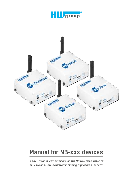
Manual for NB-xxx devices
Table of Contents. NB-xxx devices product family NB-2x1Wire NB-WLD NB-2xIn NB-2xOut Shared features of the NB-IoT product family Measurements and data upload Description.. View
NB devices manual | HW-group.com
Full PDF Document

If the inline viewer fails, it will open the original document in compatibility mode automatically. You can also open the file directly.
Extracted Text
Manual for NB-xxx devices
NB-IoT devices communicate via the Narrow Band network only. Devices are delivered including a prepaid sim card.

Safety Notices
The device complies with regulations and standards in force in the Czech Republic and the European Union. The device has been tested and is supplied in working order. To keep the device in this condition, it is necessary to adhere to the following safety and maintenance instructions.
Using the device in a manner other than prescribed by the manufacturer may cause its safeguards to fail!
The power supply outlet or disconnection point must be freely accessible.
The device must not be used in particular under any of the following conditions: � The device is noticeably damaged � The device does not function properly � Unfastened parts can move inside the device � The device has been exposed to moisture or rain � The device has been serviced by unauthorized personnel � The power adapter or power supply cable are noticeably damaged � If the device is used in a manner other than designed for, the protection provided by the
device may fail. � The local electrical system must include a power switch or a circuit breaker and overcurrent
protection.
The manufacturer warrants the device only if it is powered by the supplied power adapter or an approved power supply.

If you have any problems with installing or operating the device, please contact the technical support: HW group s. r. o. http://www.hw-group.com email: support@HWg.cz
Formansk� 296 Prague, 149 00 Phone: +420 222 511 918
Before contacting technical support, please have at hand the exact type of your device (at the type plate) and, if known, the firmware version (see later in this manual).

2

HW group

Safety Notices

Table of Contents

NB-xxx devices product family

4

NB-2x1Wire

4

NB-WLD

4

NB-2xIn

4

NB-2xOut

4

Shared features of the NB-IoT product family

5

Measurements and data upload

5

Description of HW elements

8

Setting up the device

8

Migration of connected device

13

Portals where can be devices connected to

15

SensDesk.com portal features

16

NB-Devices models and their specific features 19

NB-2x1Wire

19

NB-2xIn

20

NB-2xOut

21

NB-WLD

22

Technical specifications for all models

23

Mechanical dimensions

24

Table of Contents

NB - Devices

3

NB-xxx devices product family
NB-xxx Devices is a family of environment monitoring products using the Narrowband (NB-IoT) mobile network. All products feature robust design, battery-powered operation, and seamless integration with any portal based on the SensDesk technology. The HWg-cloud.com portal is for free, others can be paid services. All devices include a 3V alkaline CR123A battery that allows continuous operation up to 3 years (depending on the device type, application and connected sensors).

NB-2x1Wire
A device for connecting thermometers, hygrometers, or other sensors via the RJ11 1-Wire (UNI) bus. Allows connecting several sensors to measure up to 4 quantities simultaneously.

NB-WLD
Water Leak Detection unit with 1 zone input (external WLD Type A moisture-sensing cable). One zone is max. 185 m (85 m / WLD sensing + 100 m / prolong cable).

NB-2xIn
A device for connecting external detectors via DI input (door or window contact, PIR motion detector or a smoke / gas detector with relay output). Allows connecting 2 independent detectors. Each DI input can feature pulse counters for connecting energy meters with S0 output; however, external power is needed for reliable deployment.

NB-2xOut
A module with 2 DO (relay outputs) controlled from the portal (www.HWg-cloud.com or others) over the NB-IoT network.

4

HW group

NB-xxx devices product family

Shared features of the NB-IoT product family
� Robust metal design, 67 � 78 � 33 mm (without antenna) � External antenna, SMA connector � 4FF (nano SIM) holder � LED indicator � Plug & Play � connect power or remove the insulating strip and the device is immediately available
in the portal � Device & communication settings (communication period, safe ranges) are configured in the portal � Battery state appears in the portal as another sensor � Powered from a 5V adapter or the built-in replaceable CR123A battery � Default "subscribed" version of the device is delivered with 3-years prepaid simcard for Vodafone
NB-IoT network.

Subscribed = 3 years subscription NB-IoT SIM (Vodefone) included
For specifics of individual devices, including any differences in the measurement period, battery life and so on, see the respective device page.
Measurements and data upload
Measurement and data upload period The period for logging the measured values and uploading them to the portal is fully configured automatically via the portal, separately for operation with an external power source and batterypowered operation. SensDesk.com portal default values:
External power � Logging period (measuring, storing values in the internal memory): 5 minutes � Data upload period (connecting to the portal and uploading all logged values): 1 hour � Check period (NB-2xOUT brief query for output state changes): 10 minutes

NB-xxx devices product family

NB - Devices

5

Battery power � Logging period (measuring, storing values in the
internal memory): 15 minutes � Data upload period (connecting to the portal and
uploading all logged values): 10 hours � Check period (NB-2xOUT brief query for output state
changes): 1 hour
Only the Portal administrator may provides you other than automatic logging / Data update period settings (setuped per each device). Keep in mind device life time when powered from battery. Data upload period cannot be shorter than 60 minutes and the Logging period shorter than 5 minutes.
Periodic and non-periodic reading of sensors Sensors values are regularly read in the fixed Log Period, which is configured via the portal. However, in addition to the periodic reading, the values can be also read if the following happens: 1) The device is powered up by connecting the battery or an external power supply 2) The button is pressed 3) If the SafeRange is exceeded at the moment of periodic reading, the measurement is repeated
after the Delay interval
Periodic and non-periodic data upload Sensor values are uploaded to the server periodically in the fixed period, which is configured via the portal. However, in addition to the periodic upload, data can be also uploaded if the following happens: 1) SIM card is inserted 2) Device power is connected or changed 3) The button is pressed 4) SafeRange is exceeded (if the Delay is set, then only after the Delay elapses)
SafeRange � range of allowed values SafeRange is configured in the portal independently for each sensor. Whenever the measured value passing by this range, a message to the portal is sent (even out of the Data Upload period - default 10 h). To extend life time of the device powered from the battery, sensors are read only in the Logging period (default 15 min). With the exception of SD-2xIN, sensors are NOT read at other period. If a Delay is set together with the SafeRange, the repeated measurement is performed at the next Logging period, and an Alarm is raised only if the repeated measurement is also out of the SafeRange.

6

HW group

NB-xxx devices product family

Hysteresis / Idle range (sensor value)
The Hysteresis setting defines a tolerance range for suppressing alarm alerts. The function prevents multiple alarm alerts (too many emails from the portal) if the reading oscillates around the specified threshold. The hysteresis is configured independently for each sensor.

T[�C] 25 20 15 10
5

Hysteresis
Temperature range: -15 .. +25 �C Hysteresis: 5 �C Alarm ON Alarm OFF

0

-5

-10

-15

Hysteresis

-20

-25 Hysteresis = 5 �C
Alarm 0 state None Hysteresis

1 234

5 6 7 8 9 10

t[s] 11 12 13 14

The figure demonstrates two cases. Without the hysteresis idle range of 5 �C, the alarm raised in point 8 would end in point 9; however, the hysteresis function keeps the alarm active until the temperature reaches the upper limit of the tolerance band (point 10): 5 �C + (�15 �C) = �10 �C.

� Hysteresis = 5 �C � The unit sends 3 Email (SMS) messages. Alarm active in points 0..4, 8..10, 12 and beyond.
� No hysteresis (0 �C) � The unit sends 8 Email (SMS) messages. Alarm active in points 0..1, 2..3, 8..9, 12..13, 14 and beyond.

In determining when the Alarm ends, the Hysteresis value applies. The end of an Alarm is only notified when the measured value is well within the SafeRange. However, the value is only read according to the Log Period.

Alarm START notification Alarm START notification

Alarm END notification Alarm END notification

Alarm START notification Alarm END notification

Alarm state

Delay [s]

Time

Alarm status notification based on a Delay value: � Blue: Delay = 0 � Yellow: Delay is non-zero
To increase battery life, be careful when setting the SafeRange and Hysteresis values.

NB-xxx devices product family

NB - Devices

7

Description of HW elements

LED indicator (Status)

The blue LED gives a quick status indication for debugging and troubleshooting. It can indicate these states:
� Short flash � reading of sensors and inputs
� Rapid flashing � registration to the NB-IoT network

Power 5V

Status Setup
NB-SIM

� Continuously on � communication over the NB-IoT network, data transfer

When power is connected to the device, the indicator briefly lights up to indicate modem initialization and 1-Wire sensor detection. Then, it quickly flashes as the device connects to the network, and lights up whenever the device communicates with the portal. It also briefly flashes when the 1-Wire sensors or the WLD cable state are being read.

Setup button The button is used to send values to the portal immediately and to detect sensors. � Press � sensors are detected and data are sent to the portal � Press for longer than 10 s � reset to factory defaults

Setting up the device
1) Attach the external antenna 2) Connect 1-Wire sensors (NB-2x1Wire only) 3) Insert SIM card 4) With a slight force, pull out the insulating strip that insulates the battery from the contacts 5) Connect the external power supply and wait until the device connects to the operator's
network (i.e. until the blue LED turns off). Depending on the network and device configuration, this can take up to 20 minutes (when the device is first connected to an operator's network, including in a new country or region). During this time, do not disconnect external power to avoid battery drain. 6) Default portal where are devices connected is www.HWg-cloud.com. To install new device are 2 options:
a) You have existing account on the HWg-cloud and you would like to adopt new device to this one account. (See page 9)
b) You have existing account on another SensDesk technology based portal (www.SensDesk.com or www.HWportal.cz for example) and you would like to migrate new device to this one account. (See page 10)
7) Define sensor name & SD SafeRange for each sensor. (See page 12)

8

HW group

Description of HW elements / Setting up the device

6a) Adopt new device to HWg-cloud.com Open the www.HWg-cloud.com website, login to your account and go to the My Team page.
Scroll down to the Device Adoption. Fill the device hash (1234-5678 number on the label of physical device)
Device will appear after some time in the devices:

Setting up the device

NB - Devices

9

6b) Migrate new device from HWg-cloud.com to another portal
Open the www.HWg-cloud.com website, do not log in, click to Set Device button on the top of the page.

Fill the device hash (1234-5678 number on the label of physical device)

10

HW group

Setting up the device

As Team login & Team password fill data from the SensDesk technology based portal, where you have the account. You will find them on the Team page.

After you click to Save button on the web page, take a pencil or other tool and briefly press the Setup button on the device. It will start blinking (communication with the portal) and finalize device migration process.
Setting up the device

Setup button

NB - Devices

11

Device will appear in the Device list:
7) Define sensor name & SD SafeRange for each sensor Part of the device installation is to define sensor name & SD SafeRange for each sensor. Define SD SafeRange to significantly speed-up alerts when sensor value oscillate around the SafeRange limit.

12

HW group

Setting up the device

Migration of connected device
Connected and working device can be also easily migrated from one portal to another. For example in this case from paid portal www.SensDesk.com to free www.HWg-cloud.com.
Fill Team login and Team password, choose the right SensDesk technology based portal.

Migration of connected device

NB - Devices

13

After you click to Save button on the web page, take a pencil or other tool and briefly press the Setup button on the device. It will start blinking (communication with the portal) and finalize device migration process.

Device will appear on the target portal.
Only sensor names will be transferred between the portal. No more device configuration or data history!

14

HW group

Migration of connected device

Portals where can be devices connected to
NB Devices have to be connected to some online Portal based on SensDesk technology. 1) www.HWg-cloud.com is free portal provided by manufacture with limited functions. 2) www.SensDesk.com is paid portal provided by manufacture. 3) Portal providers are independent companies running their own compatible portals. List of them
is on the main page of www.HWg-cloud.com.

HWg-cloud.com � Free service � Up to 20 devices � Device management
Portal providers

SensDesk.com � Paid service � Subscription plans � SMS, Voice calls, graphs
Check list on HWg-cloud.com

. . .

Portals where can be devices connected to

NB - Devices

15

SensDesk.com portal features
Graphs of values

SMS & Voice call alerts

Enable Voice call in SMS settings

16

HW group

SensDesk.com portal features

Multigraph of several values

SensDesk.com portal features

NB - Devices

17

Other features & PDF reports

Open API (SNMP & XML)

18

HW group

SensDesk.com portal features

NB-Devices models and their specific features
NB-2x1Wire

Power 5V

Status Setup
NB-SIM

1-Wire

Antenna

Port1

Port2

A device for connecting external sensors of Temperature, Relative Humidity, Voltage or other values via the RJ11 1-Wire (UNI) bus. Allows connecting several sensors to measure up to 4 quantities simultaneously.
Sensors are detected whenever power is connected to the device or the Setup button is pressed.
The device can be powered from an external 5V adapter, from its internal battery, or using a combination of these. With a single connected Temp-1Wire IP67 temperature sensor and the default sensor reading and data upload periods, the battery lasts up to 3 years. When using 1-Wire UNI sensors, either the sensors or the NB-2x1Wire device should be powered from an external adapter because such sensors significantly reduce the battery life.

External sensors Port / connector What can be connected Sensor types Sensors / distance Alarm LED

Port1, Port2 / RJ11 (1-Wire, 1-Wire UNI) 2 external sensors. One combined temperature + humidity sensor can be also connected Only sensors by HW group s. r. o. 4 values, max. 2 probes per port (max. 60 m total length per port) Alarm Port1 � Alarm SENS � lights up if the senor is in alarm � on external power only

NB-Devices models and their specific features

NB - Devices

19

NB-2xIn

Power 5V

Status Setup
NB-SIM

Antenna

Inputs

GND IN1
GND IN2

Remote monitoring device for connecting external detectors to 2x DI (Digital Input). To each DI input you can connect a door or window contact, a PIR motion detector or a smoke / gas detector with a dry contact (relay) output.
Pulse counter (S0) on each DI input Advanced feature of each DI input is 4bytes pulse counter for counting pulses. To each DI input you can connect energy or water meter with pulses (S0) output. Only pulses longer than 20 ms are detected. Due to high energy requirements of S0 outputs, external power is required for reliable pulse counting. When device powered from internal battery, reliable operation cannot be guaranteed.
Alarm state The input mode (Alarms or Counters) can be changed in the Digital Input configuration at the portal using the "Alarm level" parameter. If the "Not Defined" option is selected (default portal configuration), DI input is in pulse counting mode and 0/1 state is communicated only in the regular data upload period. When Alarm level = 1 or Alarm level = 0, DI input is in the Alarm mode. The input 0/1 state is communicated in the regular data upload period as well as whenever there is a state change. To comply with the transmission limit, the device will send no more than 3 alarms per 10 minutes. Frequent state changes can have a significant impact on battery life. For battery operation, wiring cables should be as short as possible to avoid false pulses.
LED indication The default mode is the counter mode (i.e. Alarm level = Not defined). When DI input is activated (=1 / contact closed) and the device is powered from an external adapter, the respective green LED lights up. The LEDs are inactive on battery power.

20

HW group

NB-Devices models and their specific features

DI � Dry Contact Inputs Port / connector Type Sensitivity Max. distance Counter sensitivity LED Pulse counter
NB-2xOut

I1, I2 / terminal block � 2 mm Digital Input (supports NO/NC Dry contact) 1 (On) = 0 � 500  Up to 10 m 20 ms 2� green � input contact closed � on external power only External power required for reliable pulse counting � S0 = min 5 V / 2 � 10 mA.

Power 5V

Status Setup
NB-SIM

Antenna

Outputs

NC1 COM1
NO1 NC2 COM2 NO2

IoT monitoring device 2 DO (relay outputs) controlled from the portal over the NB-IoT network. It can be connected to any SensDesk technology based portal.
To reduce power consumption (when running from internal battery), the device using internally latching relays. To increase reliability, internal relays are energized periodically every 10 minutes. When powered from internal battery only, estimated battery life time is around 2 years.
Note: The device is not suitable for mobile applications (in car for example).

LED indication
When powered from external adapter, output states are signaled by yellow LED when output = 1. The LEDs are inactive on battery power.

Relay outputs Type Connector Rating LED

Latching (bipolar) relay Terminal block Max. 500 mA at 125 V AC, 1 A at 30 V DC 2� green � output contact closed � on external power only

NB-Devices models and their specific features

NB - Devices

21

NB-WLD

Power 5V

Status Setup
NB-SIM

Antenna

WLD sensing cable

Water Leak Detection unit with 1 zone input (external WLD Type A moisture-sensing cable). Lenght of external cable can be max. 60 m (any combination of WLD sensing + non-sensing prolong cable).
Total length max. 60 m

20 m

10 m

2m 2m

T � Terminator

Sensing cable

Connecting cable
The circuit can be extended with a 2-wire connecting cable at any place.

The flood detection is performed every 5 min. (15 min. when powered from the battery). Estimated battery life with 15 min. detection is 4 years.
If the cable is flooded or disconnected and the device is powered from an external adapter, the red LED lights up.
Note: The LED is inactive on battery power.

WLD cable Type Connector Sensor states Sensing cable length Cable extension LED

Moisture sensing cable Terminal block 0 = OK, 1 = Flooded, 2 = Cable disconnected Max. 60 m in total (WLD sensing cable + prolong cable) May be extended by at most 20 m, AWG 24 1� red � activated or cable disconnected � on external power only

22

HW group

NB-Devices models and their specific features

Technical specifications for all models

NarrowBand Supported bands
Certifications
Output power Sensitivity Antenna Supported protocols

B1 / B2 / B3 / B4 / B5 / B8 / B12 / B13 / B17 / B18 / B19 / B20 / B25 / B26* / B28 / B66
Carrier: Vodafone (Global) Deutsche Telekom / Telef�nica* (Europe) AT&T / T-Mobile / Verizon* / Sprint* (North America) LGU+* (South Korea) SoftBank / NTT DOCOMO* (Japan) Telstra* (Australia) Regulatory: GCF (Global) CE (Europe) FCC / PTCRB (North America) IC (Canada) KC (South Korea) NCC (Taiwan) JATE / TELEC (Japan) RCM (Australia) NBTC (Thailand) IMDA (Singapore) Others: RoHS ATEX (Europe)
23 dBm +- 2 dB
129 dBm
External, SMA
IP: UDP/IP (COAP)

Power Supply voltage Connector Battery

5 V DC / 120 mA Jack � 3.5 x 1.35 / 10 mm Lithium 3V model CR123A

Common LEDs Status

Blue � communicating in the NB-IoT network (on), connecting to the network (flashing), reading sensors (brief flash)

Button Setup

Short press � sensor detection, immediate upload of values on portal Pressed for longer than 10 s � reset to factory defaults

Miscellaneous Operating temperature Dimensions / weight Electromagnetic radiation EMC

-10 to +60 �C (for the device � sensors may support different operating ranges) 67 � 78 � 33 mm / 250 g CE / FCC Part 15, Class B EN 55022, EN 55024, EN 61000
* Under development

Technical specifications for all models

NB - Devices

23

Mechanical dimensions
53,5 mm

69,1 mm

67,3 mm

62,3 mm

Power 5V

Status Setup
NB-SIM

65,8 mm 31,0 mm

24

HW group

Mechanical dimensions

More monitoring devices by HW group

Poseidon2 4002
Designed for demanding monitoring applications, such as in data centers and industrial settings.

Poseidon2 3468
Remote monitoring of temperature, humidity and other sensors. Industrial version.

Poseidon2 3266/3268
Basic unit for monitoring temperature, humidity, and other sensors over the network.

Ares 10/12
Remote environment monitoring at any place with GSM coverage.

SD family
Simple devices for the monitoring of temperature, humidity, voltage, current, and other parameters.

WLD2
Quad water leak detector with WiFi and Ethernet.

NB-Devices have to be connected to one of the portals:

www.HWg-cloud.com

www.SensDesk.com

Portal providers

� SaaS (Software as a Service).
� Default portal for all HWg devices (latest FW required).
� Basic free portal for 20 HW group devices (all types).
� Simple Email alerts for 2 recipients.
� 10 days history, no API, no SMS, basic graphs.
� Devices can be migrated to any other portals.
� Based on SensDesk technology.

� SaaS (Software as a Service).
� SensDesk is technology.
� SensDesk.com is public example of this technology (by HWg).
� It`s Paid option for all HWg devices.
� 3 subscription plans (5D / 10D / 25D for 1 year).
� Differences are also in service mix (how many SMSs, PDF, ...) not device limit only.
� Any subscription plan can be ordered with 1 year voucher.

� SaaS (Software as a Service). � Paid service provided by HW
group partners. � Various mix of free / paid
services. � Based on SensDesk technology.
� SensDesk.at / .gr / .lv / .ro / ... � HWportal.cz � Other (list on HWg-cloud.com).

HW group s. r. o. Rumunsk� 26/122
Prague, 120 00 Czech Republic
Phone: +420 222 511 918 Fax: +420 222 513 833
www.HW-group.com
manual version: 1.0.6