Bard MEGA-TEC® Series Air Conditioner Specifications
Brand: Bard
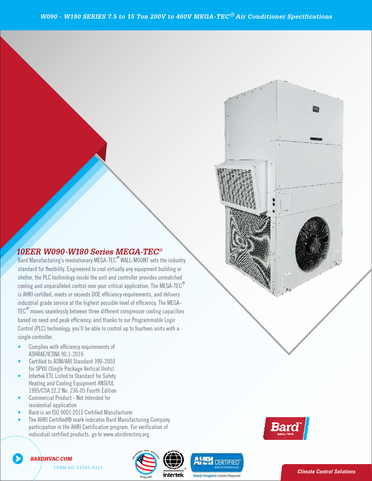
Series: W090 - W180 Series MEGA-TEC®
Product Overview
The Bard MEGA-TEC® WALL-MOUNT series represents an industry standard for flexible and efficient cooling solutions. Engineered for equipment buildings and shelters, these units feature advanced PLC technology for unparalleled control over critical applications. The MEGA-TEC® is AHRI certified, meets or exceeds DOE efficiency requirements, and delivers industrial-grade service with high efficiency. Units can seamlessly transition between three compressor cooling capacities, and the Programmable Logic Control (PLC) technology allows control of up to fourteen units with a single controller.
Nomenclature Breakdown
The model number provides detailed configuration information:
W090-W180 Series Nomenclature
| Code | Description |
|---|---|
| Unit Series (W) | Wall Mount |
| Nominal Capacity (090-180) | 7.5 Ton (W090), 10 Ton (W120), 12.5 Ton (W150), 15 Ton (W180) |
| Revision (A/B) | Revision identifier |
| Control Logic & Climate Options (P/E) | P: PLC Logic Board, E: Electric Reheat Dehumidification |
| Volts & Phase (B/C/N/Q/S/T) | Voltage and phase configuration (e.g., B: 208/230-60-3, C: 460-60-3, Q: 575-60-3, S: 208/230-60-3*, T: 460-60-3*) |
| Electric Heat Options (KW) (0Z/09/18/36) | 0Z: 0kW, 09: 9kW, 18: 18kW, 36: 36kW (36kW only for Q voltage) |
| Vent Option (B/E) | B: No Vent, E: Economizer (DB & WB) |
| Filter (M/P/N) | M: MERV 11 2" Pleated, P: MERV 8 2" Pleated, N: MERV 13 2" Pleated |
| Color (X/1/4/S) | X: Beige, 1: White, 4: Buckeye Gray, S: Stainless Steel |
| Outlet (X) | X: Standard |
| Coil & Unit Coating Options (X/1/2/3) | X: Standard, 1: Coated Evaporator, 2: Coated Condenser, 3: Coated Evaporator & Condenser |
| Packaging Options (X/1/2/3/6/7) | X: Standard wood skid, 1: White steel skid/platform, 2: Wood skid with crate, 3: White steel skid/platform with crate, 6: Gray steel skid/platform, 7: Gray steel skid/platform with crate |
* See unit specifications for 50Hz operation. Reheat dehumidification models are only available with 18kW electric heat.
Engineered Features - Exterior
The exterior is designed for durability and serviceability, featuring:
- Durable Cabinet Construction: Galvanized 16-gauge zinc-coated steel with a baked-on, white textured enamel finish, tested to withstand 1000 hours of salt spray per ASTM B117-03. Stainless steel construction is also available.
- Lifting Lug Plates: Standard heavy-duty plates for lifting and installation.
- Easy Filter Access: Hinged door for quick access to filters and internal components.
- Filter Replacement Light: External indicator for filter changes.
- Outdoor Temperature Sensor: Measures ambient temperature and humidity for free cooling optimization.
- Access Panels: Dedicated panels for Evaporator Fan, Control Panel, Condenser Section, Lockable Breaker Access, and Service Ports ensure easy maintenance.
- Optional Economizer Vent Intake: Pre-filters and damper motors for free cooling.
- Power Entrances: Weather-resistant plugs for low and high voltage power access on both sides.
- Condenser Coil Intake Access: Removable side panels for easy cleaning.
- Optional Drain Location: Condensate drains can be routed through the front or base.
Engineered Features - Interior
The interior is designed for efficient operation and ease of service:
- Non-fiberglass Insulation: Durable closed-cell foam insulation.
- Enhanced Cooling Modes: PLC logic supports high sensible cooling for low humidity areas and balanced climate operation for high humidity removal.
- Industrial Grade Fans: ECM technology for efficient, dependable service with Modbus communication.
- Refrigeration Circuits: Two independent circuits with separate scroll compressors for reliability and serviceability.
- 2" Pleated Filter: Large filter area for improved airflow.
- Dirty Filter Indicator: Standard on all models.
- Fan Pressure Switch: Standard on all models to indicate blower failure.
- Electronic Expansion Valves (EEVs): Used for precise superheat control.
- PLC Technology: Modbus communication for control and monitoring.
- Optional Free Cooling: Economizer utilizes outdoor air for cooling when conditions are favorable.
- Liquid Line Filter/Drier: Standard on all models for refrigerant protection.
- Phase Rotation Monitor: Standard on 3-phase models to protect against compressor reverse rotation.
- Pressure Transducers: Monitor high and low side system pressures for refrigeration data.
- Slide-out Fan Assembly: Allows for easy fan removal and rotation for compressor access.
- Scroll Compressors: Provide efficient capacity control across three stages.
Unit Modes of Operation
- Cooling Operation: Three-stage cooling using R410A refrigerant with two independent circuits. PLC monitors humidity and adjusts operation for sensible or latent cooling needs.
- Heating Operation (Optional): Two-stage electric heat operation.
- Electric Reheat Dehumidification Operation (Optional): Reheats cooled supply air to remove excess moisture, lowering high humidity levels.
- Economizer Free Cooling Operation (Optional): Utilizes cooler outdoor air for cooling, reducing energy use. Operates down to -40°F.
- Balanced Climate™ Operation: Standard feature for moisture removal during cooling by reducing airflow and increasing latent capacity.
Capacity and Efficiency Ratings
The MEGA-TEC® series offers various cooling capacities and efficiencies:
| Model | 3rd Stage Cooling Capacity BTUH | 3rd Stage Cooling Capacity EER | 2nd Stage Cooling Capacity BTUH | 1st Stage Cooling Capacity BTUH | IPLV |
|---|---|---|---|---|---|
| W090A | 90,000 BTUH | 10.2 EER | 80,000 BTUH | 30,000 BTUH | 11.7 |
| W120A | 123,000 BTUH | 10.0 EER | 114,000 BTUH | 42,000 BTUH | 12.3 |
| W150A | 146,000 BTUH | 10.0 EER | 122,000 BTUH | 44,000 BTUH | 10.6 |
| W180B | 178,000 BTUH | 10.0 EER | 150,000 BTUH | 58,000 BTUH | 12.6 |
Notes:
- Capacity certified per ANSI/ARI Standard 390-2003. Meets or exceeds 10 EER DOE requirements.
- EER certified per ANSI/ARI Standard 390-2003. Ratings based on 100% closed fresh air intake.
- IPLV is a BTU/WATT efficiency measurement combining staged cooling.
Application Data
Extensive tables provide cooling capacity data (BTUH and KW) for various indoor/outdoor temperature conditions and operating modes (Standard Cooling, High Sensible Cooling, Balanced Climate). These tables detail total and sensible cooling capacities across different stages and return air conditions. Airflow capacity multipliers are also provided to adjust performance based on actual unit airflow.
Electrical Specifications
Detailed electrical specifications are provided for single and dual circuit configurations across various voltage-phase options (208/230V, 400V, 460V, 575V). Tables include Minimum Circuit Ampacity (MCA), Maximum Operating Circuit Protection (MOCP), Field Power Wire Size, and Ground Wire Size per UL1995 standards.
Ventilation Options
- Code B: No Ventilation - Unit construction excludes intake and exhaust openings.
- Code E: Economizer - Features free cooling using outdoor air, with optional enthalpy control. Requires field-installed hoods.
Cabinet and Coil Options
- Cabinet Finishes: Available in Beige, White, Buckeye Gray, and Stainless Steel (W090, W120, W150 only). Construction uses 16-gauge zinc-coated steel with a durable polyurethane primer and baked-on textured enamel finish.
- Coil Coating: Standard Green Fin Hydrophilic coating on evaporator coils for water attraction and corrosion protection. Optional TechniCoat AA offers enhanced resistance to harsh environments.
Packaging Options
Units can be shipped via standard wood skid, white or gray metal platform, or with optional crates for enhanced protection during transit. Specific dimensions and materials are detailed for W090A-W120A and W180B series.
Standard Unit Components
Key factory-supplied components include:
- Refrigerant Components: Scroll compressors, crankcase heaters, electronic expansion valves (EEVs), high/low pressure transducers, and high-pressure control switches.
- Temperature Sensors: Discharge Air (SAT), Return Air (RAT), Mixed Air (MAT), Freeze Sensor (FS), and Outdoor Air Temp/Humidity (OAT/OAH).
- Air Pressure Sensors: Evaporator Fan Airflow Switch (AFS) and Dirty Filter Switch Indicator (DFS).
- Electrical Components: Programmable Logic Board (PLC), Compressor Control Module (CCM), Phase Monitor (PM), Compressor Contactor (CC), Circuit Breaker (CB), and Toggle Disconnect (TD).
- Fans: Indoor Evaporator Fan Assembly (IFM) and Outdoor Fan Assembly (OFM) utilize ECM motors.
- Electric Heat Components: Heat Strip (HS) and Heat Contactor (HC) for optional heating.
Controller Options
Bard offers several controller options for managing the MEGA-TEC® units:
- PGD Temperature Controller: Simple single-unit control with temperature monitoring via a backlit display.
- PGDx Temperature and Humidity Controller: Single-unit control with temperature and humidity monitoring via a color touchscreen display.
- LC6000 Multi-Unit Controller: Advanced controller capable of managing up to 14 units across 3 zones, offering features like remote monitoring, Modbus control, emergency functions, and webpages for system access.
Optional accessories include zone sensors, service tools, EMI ferrite filters, and EEV manual adjustment tools.
Software Features
The MEGA-TEC® PLC and LC6000 controllers offer various software features:
- Standard Cooling Mode: Balances sensible and latent cooling.
- High Sensible Cooling Mode: Increases sensible capacity for low humidity environments.
- Balanced Climate Cooling Mode: Reduces airflow to enhance moisture removal in high humidity.
- Compressor Cooling Staging: Utilizes up to three stages for optimal capacity control.
- Free Cooling Mode (Optional): Leverages economizer for cooling with outdoor air.
- Heating Mode (Optional): Provides optional 2-stage electric heat.
- Electric Reheat Dehumidification Mode (Optional): Combines compressor cooling with electric heat for enhanced dehumidification.
- Emergency Cooling Mode: Utilizes economizer and compressor cooling during high temperature events.
- Stand Alone Mode: Allows unit operation without LC6000 connection.
- Orphan Mode: Enables continued cooling if LC6000 communication is lost.
- Alarm Logging: Records unit alarms for diagnostics.
- Software Updates: Accessible via Bard website.
- Self Test Operation: Diagnostic feature for verifying system functions.
- A/C Circuit Monitoring: Displays operational pressures for diagnostics.
Wiring and Site Equipment Inputs/Outputs
The LC6000 controller supports Ethernet, Modbus, and Webpage remote access. Wired inputs are available for Emergency Off, Emergency Vent, Generator Run, and Bard Guard security. Wired alarm outputs provide notifications for various conditions including humidity, temperature, unit alarms, and zone-specific alarms.
Dimensions and Clearances
Detailed cabinet dimensions and required clearance areas are provided for W090A, W120A, W150A, and W180B series units, including diagrams for unit layout and installation spacing.
Non-Ducted Supply and Return Grilles
Information on available supply and return grilles, including descriptions, weights, and spread/throw characteristics for optimal air distribution.