N9021B MXA Signal Analyzer
File info: application/pdf · 24 pages · 1.02MB
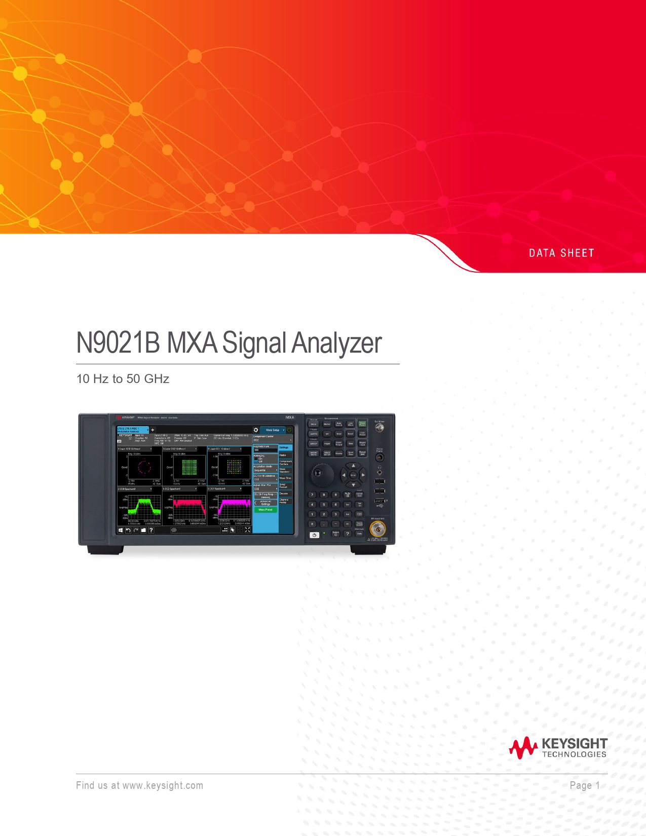
N9021B MXA Signal Analyzer
N9021B, MXA, signal, analyzer, spectrum, 5G, NR
N9021B MXA Signal Analyzer - Keysight
Samples of this product have been type tested in accordance with the Keysight Environmental Test Manual and verified to be robust against the environmental ...
Full PDF Document

If the inline viewer fails, it will open the original document in compatibility mode automatically. You can also open the file directly.
Extracted Text
N9021B MXA Signal Analyzer
10 Hz to 50 GHz

Find us at www.keysight.com

Page 1

Table of Contents
Definition and Terms................................................................................................................................ 3 Frequency and Time Specifications ......................................................................................................... 4 Amplitude Accuracy and Range Specifications......................................................................................... 6 Dynamic Range Specifications ................................................................................................................ 9 Powersuite Specifications ...................................................................................................................... 13 General Specifications........................................................................................................................... 14 Inputs and Outputs ................................................................................................................................ 16 IQ analyzer............................................................................................................................................ 19 IQ analyzer � Option B2X ...................................................................................................................... 22 IQ analyzer � Option B5X ...................................................................................................................... 23 Real-time spectrum analyzer ................................................................................................................. 24 Option RT1 and RT2............................................................................................................................. 24

Find us at www.keysight.com

Page 2

Definition and Terms
Specifications describe the performance of parameters covered by the product warranty and apply to the full temperature range of 0 to 55 �C, unless otherwise noted.
95th percentile values indicate the breadth of the population (approx. 2 ) of performance tolerances expected to be met in 95 percent of the cases with a 95 percent confidence, for any ambient temperature in the range of 20 to 30 �C. In addition to the statistical observations of a sample of instruments, these values include the effects of the uncertainties of external calibration references. These values are not warranted. These values are updated occasionally if a significant change in the statistically observed behavior of production instruments is observed.
Typical values describe additional product performance information that is not covered by the product warranty. It is performance beyond specifications that 80 percent of the units exhibit with a 95 percent confidence level over the temperature range 20 to 30 �C. Typical performance does not include measurement uncertainty.
Nominal values indicate expected performance, or describe product performance that is useful in the application of the product, but are not covered by the product warranty.
The analyzer will meet its specifications when:
� It is within its calibration cycle � Under auto couple control, except when Auto Sweep Time Rules = Accy � Signal frequencies < 10 MHz, with DC coupling applied � The analyzer has been stored at an ambient temperature within the allowed
operating range for at least two hours before being turned on � The analyzer has been turned on at least 30 minutes with Auto Align set to
Normal, or, if Auto Align is set to off or partial, alignments must have been run recently enough to prevent an Alert message; if the Alert condition is changed from "Time and Temperature" to one of the disabled duration choices, the analyzer may fail to meet specifications without informing the user

Quickly adapt to evolving test requirements
Industries from wireless to satellite communications require wider analysis bandwidth to meet demands for higher data throughput. As higher bandwidth technologies such as 5G NR move into mainstream use, engineers need tools for design validation and manufacturing that offer the accuracy, speed, and bandwidth to accelerate device development. Keysight's new N9021B MXA Signal Analyzer offers best-in-class bandwidth and phase noise for accurate and repeatable signal analysis across millimeter-wave and 5G NR frequencies.

This data sheet is a summary of the specifications and conditions for the N9021B MXA signal analyzer. For the complete specifications guide, visit:
www.keysight.com/find/N9021B

Find us at www.keysight.com

Page 3

Frequency and Time Specifications

Frequency range Option 532 Option 544 Option 550

Band 0 1 2 3 4 5 6

LO Multiple (N) 1 1 2 2 4 4 8

Frequency reference Accuracy
Aging rate

Temperature stability 20 to 30 �C Full temperature range

DC coupled 10 Hz to 32 GHz 10 Hz to 44 GHz 10 Hz to 50 GHz
Swept or FFT, with FFT width  40 MHz 10 Hz to 3.6 GHz 3.5 to 8.4 GHz 8.3 to 13.6 GHz 13.5 to 17.1 GHz 17.0 to 26.5 GHz 26.4 to 34.5 GHz 34.4 to 50 GHz

FFT, with FFT width > 40 MHz 10 Hz � 3.4 GHz 3.4 � 8.2 GHz 8.2 � 13.2 GHz 13.2 � 17.1 GHz 17.1 � 26.5 GHz 26.5 � 34.5 GHz 34.5 � 50 GHz

� [(time since last adjustment x aging rate) + temperature stability + calibration accuracy]

Option PFR

Standard

� 1 � 10 -7 / year

� 1 � 10 -6 / year

� 1.5 � 10 -7 / 2 years Option PFR

Standard

� 1.5 � 10 -8

� 2 � 10 -6

� 5 � 10 -8

� 2 � 10 -6

Achievable initial calibration accuracy Option PFR

Standard

� 4 � 10 -8

� 1.4 � 10 -6

Residual FM ( with option PFR) Residual FM ( Standard)

 (0.25 Hz � N)p-p in 20 ms (nominal)  (10 Hz � N)p-p in 20 ms (nominal)

Frequency readout accuracy (start, stop, center, marker)

� (marker frequency x frequency reference accuracy + 0.25 % x span + 5 % x RBW + 2 Hz + 0.5 x horizontal resolution1)

Marker frequency counter Accuracy Delta counter accuracy Counter resolution

� (marker frequency x frequency reference accuracy + 0.100 Hz) � (delta frequency x frequency reference accuracy + 0.141 Hz) 0.001 Hz

Frequency span (FFT and swept mode)

Range

0 Hz (zero span), 10 Hz to maximum frequency of instrument

Resolution

2 Hz

Accuracy

Stepped/Swept

� (0.25 % x span + horizontal resolution)

FFT

� (0.1% x span + horizontal resolution)

1. Horizontal resolution is span/(sweep points � 1).

Find us at www.keysight.com

Page 4

Sweep time and triggering Range
Accuracy
Trigger Trigger delay

Span = 0 Hz

1 �s to 6000 s

Span  10 Hz

1 ms to 4000 s

Span = 0 Hz, swept � 0.01 % (nominal)

Span  10 Hz, FFT � 40 % (nominal)

Span = 0 Hz

� 0.01 % (nominal)

Free run, line, video, external 1, external 2, RF burst, periodic timer

Span = 0 or FFT

-150 to +500 ms

Span  10 Hz, swept 0 �s to 500 ms

Resolution

0.1 �s

Time gating Gate methods Gate length range Gate delay range Gate delay jitter

Gated LO; gated video; gated FFT 100.0 ns to 5.0 s (Except method = FFT) 0 to 100.0 s 33.3 ns p-p (nominal)

Sweep (trace) point range

All spans

1 to 40,001

Resolution bandwidth (RBW) EMI bandwidths (CISPR compliant) EMI bandwidths (Mil STD 461 compliant) Range (with -3 dB bandwidth, standard)
With option B2X/B5X and Option RBE
Bandwidth accuracy (power) 1 Hz to 750 kHz 820 kHz to 1.2 MHz (< 3.6 GHz CF) 1.3 to 2 MHz (< 3.6 GHz CF) 2.2 to 3 MHz (< 3.6 GHz CF) 4 to 8 MHz (< 3.6 GHz CF)
Bandwidth accuracy (-3 dB) 1 Hz to 1.3 MHz Selectivity (-60 dB/-3 dB)

200 Hz, 9 kHz, 120 kHz, 1 MHz 10 Hz, 100 Hz, 1 kHz, 10 kHz, 100 kHz, 1 MHz 1 Hz to 3 MHz (10% steps), 4, 5, 6, 8 MHz 10, 15, 20, 25, 30, 40, 50, 60, 70, 80, 100, 133, 150, 200, and 212 MHz, in spectrum analyzer mode and zero span
� 1.0 % (� 0.044 dB) � 2.0 % (� 0.088 dB) � 0.07 dB (nominal) � 0.15 dB (nominal) � 0.25 dB (nominal) � 2% (nominal) 4.1: 1 (nominal)

Video Bandwidth (VBW) Range Accuracy

1 Hz to 3 MHz (10% steps), 4, 5,6, 8 MHz, and wide open (labeled 50 MHz) �6%, nominal

Analysis bandwidth 1 Maximum bandwidth

Option B2X Option B5X

255 MHz 510 MHz

1. Analysis bandwidth is the instantaneous bandwidth available around a center frequency over which the input signal can be digitized for further analysis or processing in the time, frequency, or modulation domain

Find us at www.keysight.com

Page 5

Amplitude Accuracy and Range Specifications

Amplitude range

Measurement range

Preamp Off

Displayed average noise level (DANL) to +30 dBm

Preamp On

Displayed average noise level (DANL) to +20 dBm

Input attenuator range

0 to 70 dB in 2 dB steps

Maximum safe input level

Average total power

+30 dBm (1 W)

Peak pulse power

+50 dBm (100 W)

< 10 �s pulse width, < 1% duty cycle, and input attenuation  30 dB

DC volts Display range

� 0.2 Vdc

Log scale

0.1 to 1 dB/division in 0.1 dB steps

1 to 20 dB/division in 1 dB steps (10 display divisions)

Linear scale

10 divisions

Scale units

dBm, dBmV, dBV, dBmA, dBA, V, W, A, dBuV/m, dBuA/m, dBpT, dBG, dBpW

Electronic attenuator (option EA3)

Frequency range

10 Hz to 3.6 GHz 1

Attenuation range

Electronic attenuator range 0 to 24 dB, 1 dB steps

Full attenuation range

0 to 94 dB, 1 dB steps (Mechanical + Electronic)

1. Frequency range of option EA3 varies according to sweep types. Please refer to the frequency band definition on page 4

Preamplifier Frequency range
Gain
Noise figure

Option P32 Option P44 Option P50 100 kHz to 3.6 GHz 3.6 to 26.5 GHz 26.5 to 50 GHz 100 kHz to 3.6 GHz 3.6 to 8.4 GHz 8.4 to 13.6 GHz 13.6 to 50 GHz

100 kHz to 32 GHz 100 kHz to 44 GHz 100 kHz to 50 GHz +20 dB nominal +35 dB, nominal +40 dB, nominal 11 dB, nominal 9 dB, nominal 10 dB, nominal DANL + 176.24 dB, nominal

Find us at www.keysight.com

Page 6

Frequency response

Specification

95th percentile

20 to 30�, preselector centering applied above 3.6 GHz

Preamp Off

20 Hz to 10 MHz

�0.43 dB

�0.23 dB

10 dB attenuation

10 to 50 MHz

�0.43 dB

�0.21 dB

50 to 3.6 GHz

�0.36 dB

�0.22 dB

3.5 to 5.2 GHz

�1.5 dB

�0.76 dB

5.2 to 8.4 GHz

�1.3 dB

�0.56 dB

8.3 to 13.6 GHz

�1.8 dB

�0.67 dB

13.5 to 17.1 GHz

�1.8 dB

�0.62 dB

17.0 to 22.0 GHz

�1.8 dB

�0.73 dB

22.0 to 26.5 GHz

�2.3 dB

�0.76 dB

26.4 to 34.5 GHz

�2.3 dB

�0.82 dB

34.4 to 50 GHz

�3.0 dB

�1.21 dB

Preamp On 0 dB attenuation

100 kHz to 50 MHz 50 MHz to 3.6 GHz

�0.7 dB �0.55 dB

�0.31 dB �0.25 dB

3.5 to 5.2 GHz

�1.8 dB

�0.78 dB

5.2 to 8.4 GHz

�1.8 dB

�0.63 dB

8.3 to 13.6 GHz

�2.1 dB

�0.51 dB

13.5 to 17.1 GHz

�2.3 dB

�0.8 dB

17.0 to 22.0 GHz

�2.6 dB

�0.94 dB

22 to 26.5 GHz

�3.3 dB

�0.96 dB

26.4 to 34.5 GHz

�2.8 dB

�1.04 dB

34.4 to 50 GHz

�3.9 dB

�1.37 dB

Input attenuation switching uncertainty

Attenuation > 2 dB, Preamp off, Relative to 10 dB

50 MHz (ref frequency)

� 0.20 dB

� 0.08 dB, typical

20 Hz to 3.6 GHz

� 0.3 dB, nominal

3.5 to 8.4 GHz

� 0.5 dB, nominal

8.3 to 13.6 GHz

� 0.7 dB, nominal

13.5 to 26.5 GHz

� 0.7 dB, nominal

26.4 to 50 GHz

� 1.0 dB, nominal

Total absolute amplitude accuracy
10 dB attenuation, 20 to 30 �C, 1 Hz  RBW  1 MHz, input signal �10 to �50 dBm, RF preselector Off, Preamp Off and On, all settings auto-coupled except Auto Swp Time = Accy, any reference level, any scale,  = nominal standard deviation)

Preamp Off

At 50 MHz At all frequencies

� 0.45 dB, � 0.19 dB (95% percentile) Specification: � (0.45 dB + freq response)

95% percentile: � (0.19 dB + freq response@ 95% percentile)

Preamp On

At all frequencies

� (0.49 dB + frequency response)

Find us at www.keysight.com

Page 7

Input voltage standing wave ratio (VSWR)

95% percentile

Preamp Off, Input atten 10 dB

10 MHz to 3.6 GHz

1.125

3.5 to 8.4 GHz

1.162

8.3 to 13.6 GHz

1.217

13.5 to 17.1 GHz

1.262

17.0 to 26.5 GHz

1.319

26.4 to 34.5 GHz

1.546

Preamp On, Input atten 0 dB

34.4 to 50 GHz 10 MHz to 3.6 GHz

1.676 1.386

3.5 to 8.4 GHz

1.539

8.3 to 13.6 GHz

1.385

13.5 to 17.1 GHz

1.345

17.0 to 26.5 GHz

1.372

26.4 to 34.5 GHz

1.571

34.4 to 50 GHz

1.725

RBW switching uncertainty (reference to 30 kHz RBW)

1 Hz to 1.5 MHz RBW 1.6 to 3 MHz RBW 4, 5, 6, 8 MHz RBW

� 0.05 dB � 0.10 dB � 1.0 dB

Reference level

Range

Log scale

�170 to +30 dBm in 0.01 dB steps

Linear scale

Same as log (707 pV to 7.07 V)

Accuracy

0 dB

Display scale switching uncertainty

Switching between linear and

log

0 dB

Log scale/div switching Display scale fidelity -10 dBm < mixer level < -80 dBm
Detector type

0 dB � 0.10 dB total

Normal, peak, sample, negative peak, log power average, RMS average, and voltage average

Find us at www.keysight.com

Page 8

Dynamic Range Specifications
1 dB gain compression (two-tone) (At 1 kHz RBW with 100 kHz tone spacing, 20 to 30�C) Preamp Off
20 MHz to 3.6 GHz 3.6 to 16 GHz 16 to 26.5 GHz 26.5 to 50 GHz Preamp On 10 MHz to 3.6 GHz 3.6 to 26.5 GHz
Tone spacing 100 kHz to 20 MHz Tone spacing > 70 MHz 26.5 to 50 GHz

+5 dBm, nominal +8 dBm, nominal +7 dBm, nominal 0 dBm, nominal
-14 dBm, nominal
-28 dBm, nominal -20 dBm, nominal -30 dBm, nominal

Displayed average noise level (DANL)

Input terminated, 1 Hz RBW, sample or average detector, averaging type = Log, 0 dB input attenuation, IF Gain = High, 20 to 30 �C,

with wideband options (MPB, B2X, or B5X)

Preamp Off

10 Hz

-123 dBm, nominal

20 Hz

-129 dBm, nominal

100 Hz

-126 dBm, nominal

1 kHz

-146 dBm, nominal

9 kHz to 5 MHz

-147 dBm, typical

5 to 10 MHz

-155 dBm

-158 dBm, typical

10 MHz to 1.2 GHz

-154 dBm

-157 dBm, typical

1.2 to 2.1 GHz

-152 dBm

-155 dBm, typical

2.1 to 3 GHz

-151 dBm

-154 dBm, typical

3 to 3.6 GHz

-150 dBm

-153 dBm, typical

3.5 to 4.2 GHz

-143 dBm

-147 dBm, typical

4.2 to 6.6 GHz

-144 dBm

-148 dBm, typical

6.6 to 8.4 GHz

-147 dBm

-149 dBm, typical

8.3 to 13.6 GHz

-147 dBm

-149 dBm, typical

13.5 to 14 GHz

-143 dBm

-147 dBm, typical

14 to 17.1 GHz

-145 dBm

-148 dBm, typical

17 to 22.5 GHz

-145 dBm

-146 dBm, typical

22.5 to 26.5 GHz

-139 dBm

-143 dBm, typical

26.4 to 30 GHz

-140 dBm

-143 dBm, typical

30 to 34.5 GHz

-138 dBm

-143 dBm, typical

34.4 to 37 GHz

-134 dBm

-139 dBm, typical

37 to 40 GHz

-132 dBm

-138 dBm, typical

40 to 49 GHz

-130 dBm

-136 dBm, typical

49 to 50 GHz

-128 dBm

-135 dBm, typical

Find us at www.keysight.com

Page 9

Displayed average noise level (continued)

Preamp On

100 kHz to 5 MHz

-159 dBm, typical

5 to 10 MHz

-163 dBm

-167 dBm, typical

10 MHz to 1.2 GHz

-164 dBm

-166 dBm, typical

1.2 to 2.1 GHz

-163 dBm

-165 dBm, typical

2.1 to 3.6 GHz

-162 dBm

-164 dBm, typical

3.5 to 8.4 GHz

-158 dBm

-161 dBm, typical

8.3 to 13.6 GHz

-160 dBm

-162 dBm, typical

13.5 to 17.1 GHz

-161 dBm

-163 dBm, typical

17 to 20 GHz

-160 dBm

-162 dBm, typical

20 to 26.5 GHz

-158 dBm

-160 dBm, typical

26.4 to 30 GHz

-157 dBm

-159 dBm, typical

30 to 34.5 GHz

-155 dBm

-158 dBm, typical

34.5 to 37 GHz

-153 dBm

-157 dBm, typical

37 to 40 GHz

-152 dBm

-155 dBm, typical

40 to 44 GHz

-149 dBm

-154 dBm, typical

44 to 46 GHz

-149 dBm

-154 dBm, typical

46 to 50 GHz

-146 dBm

-151 dBm, typical

DANL with noise floor extension (option NF2)

DANL improvement exceeds 9 dB with 95% confidence in the average of all bands, paths, frequency options and signal path option (MPB).

Band

Frequency

Preamp Off

Preamp On

0, f > 20 MHz

10 Hz to 3.5 GHz

-163 dBm

-174 dBm

1

3.5 to 8.4 GHz

-159 dBm

-172 dBm

2

8.3 to 13.6 GHz

-159 dBm

-172 dBm

3

13.5 to 17.1 GHz

-159 dBm

-173 dBm

4

17.0 to 26.5 GHz

-154 dBm

-169 dBm

5

26.4 to 34.5 GHz

-153 dBm

-167 dBm

6

34.4 to 50 GHz

-144dBm

-158 dBm

Spurious response

Residual responses Images response

200 kHz to 8.4 GHz (swept) Zero span or FFT or other frequencies 10 MHz to 3.6 GHz

f �645 MHz,

3.5 to 13.6 GHz

Mixer level -10 dBm

13.5 to 17.1 GHz

17.0 to 22 GHz

22 to 26.5 GHz

26.5 to 34.5 GHz

34.4 to 42 GHz

42 to 50 GHz

LO related spurious (f >600 MHz from carrier)

10 MHz to 3.6 GHz

-100 dBm -100 dBm nominal -80 dBc, -108 dBc typical -78 dBc, -87 dBc typical -74 dBc, -85 dBc typical -70 dBc, -81 dBc typical -68 dBc, -77 dBc typical -70 dBc, -94 dBc typical -60 dBc, -79 dBc typical -75 dBc, nominal
-90 dBc typical

Find us at www.keysight.com

Page 10

Other spurious

Mixer level

Response

Carrier frequency  3 GHz

-80 dBc nominal

Carrier frequency 3 to 26.5 GHz

First RF order (f  10 MHz from carrier)
Higher RF order (f  10 MHz from carrier)

-10 dBm -40 dBm

-80 dBc + 20log(N1), including IF feedthrough, LO harmonic mixing responses
-80 dBc + 20log(N1), including higher order mixer response

Carrier frequency > 26.5 GHz
First RF order (f  10 MHz from carrier)
Higher RF order (f  10 MHz from carrier)

-30 dBm -30 dBm

-90 dBc nominal -90 dBc nominal

1. N is the LO multiplication factor. Refer to page 4 for the N value verses frequency ranges.

Second harmonic distortion (SHI)

Preamp Off Mixer level at -15 dBm
Preamp On

Source frequency 10 MHz to 1.0 GHz 1.0 to 1.8 GHz 1.75 to 3 GHz 3 to 6.5 GHz 6.5 to 10 GHz 10 to 13.25 GHz 13.2 to 25 GHz Source frequency 10 MHz to 1.8 GHz 1.8 to 13.25 GHz 13.25 to 25 GHz

2. Preamp level = Input level � Input Attenuation

Preamp level 2 -45 dBm -50 dBm -50 dBm

Distortion -63 dBc -60 dBc -69 dBc -74 dBc -72 dBc -65 dBc -70 dBc nominal Distortion -78 dBc -60 dBc -50 dBc

SHI +48 dBm, +55 dBm typical +45 dBm, +57 dBm typical +54 dBm, +60 dBm typical +59 dBm, +67 dBm typical +57 dBm, +70 dBm typical +50 dBm, +61 dBm typical
+55 dBm nominal SHI +33 dBm nominal +10 dBm nominal 0 dBm nominal

Third-order intermodulation distortion (TOI)

Two �18 dBm tones at input at input mixer with tone separation at 100 kHz, 20 to 30 �C

Preamp Off

10 to 150 MHz

+14.5 dBm, +19.5 dBm typical

150 to 300 MHz

+16 dBm, +20 dBm typical

300 MHz to 1.1 GHz

+17 dBm, +21 dBm typical

1.1 to 3.6 GHz

+21 dBm, +22.5 dBm typical

3.5 to 8.4 GHz

+18 dBm, +20 dBm typical

8.3 to 13.6 GHz

+18 dBm, +23 dBm typical

13.5 to 17.1 GHz

+13 dBm, +16.5 dBm typical

17.0 to 26.5 GHz

+13 dBm, +16 dBm typical

26.4 to 34.5 GHz

+12 dBm, +19 dBm typical

34.4 to 50 GHz

+8 dBm, +12 dBm typical

Preamp On

Two tone at preamp input

Two -45 dBm

10 MHz to 500 MHz

+4 dBm nominal

500 MHz to 3.6 GHz

+4.5 dBm nominal

Two -50 dBm

3.6 to 26.5 GHz

-15 dBm nominal 3

Find us at www.keysight.com

Page 11

Phase noise
20 to 30 �C, CF = 1 GHz

Offset
10 Hz 100 Hz 1 kHz 10 kHz 100 kHz 1 MHz 10 MHz

Specification
-94 dBc/Hz -121 dBc/Hz -129 dBc/Hz -129 dBc/Hz -145 dBc/Hz -155 dBc/Hz

3. Exception for frequencies between 13.6 to 17.6 GHz, TOI is -18 dBm nominal

Typical
-80 dBc/Hz nominal -100 dBc/Hz typical -124 dBc/Hz typical -130 dBc/Hz typical -130 dBc/Hz typical -146 dBc/Hz typical -158 dBc/Hz typical

Find us at www.keysight.com

Page 12

Powersuite Specifications

Channel Power

Amplitude accuracy, W-CDMA or IS95 (20 to 30 �C, attenuation = 10 dB)

� 0.82 dB

� 0.23 dB (95th percentile)

Occupied bandwidth

Frequency accuracy

� [span/1000] nominal

Adjacent channel power

Adjacent

Accuracy, W-CDMA (ACLR) (at specific mixer levels and ACLR ranges)

MS

� 0.14 dB

BTS

� 0.49 dB

Dynamic range

Without noise correction

-73 dB typical

With noise correction

-78 dB typical

Offset channel pairs measured

1 to 6

ACP measurement and transfer time (fast method)

10 ms nominal ( = 0.2 dB)

Multiple number of carriers measured

Up to 12

Alternate
� 0.18 dB � 0.42 dB
-79 dB typical -82 dB typical

Power statistics CCDF

Histogram resolution

0.01 dB

Harmonic distortion

Maximum harmonic number Result
Intermod (TOI)

10th Fundamental power (dBm), relative harmonics power (dBc), total harmonic distortion in %
Measure the third-order products and intercepts from two tones

Burst power

Methods Result

Power above threshold, power within burst width Single burst output power, average output power, max. power, minimum power within burst, burst width

Spurious emission

W-CDMA (1 to 3.6 GHz) table-driven spurious signals; search across regions

Dynamic range

81.3 dB

Absolute sensitivity

�84.5 dBm

82.2 dB typical -89.5 dBm typical

Spectrum emission mask (SEM)

cdma2000� (750 kHz offset) Relative dynamic range (30 kHz RBW) Absolute sensitivity Relative accuracy
3GPP W-CDMA (2.515 MHz offset) Relative dynamic range (30 kHz RBW) Absolute sensitivity Relative accuracy

78.6 dB �99.7 dBm � 0.12 dB
81.9 dB �99.7 dBm � 0.16 dB

84.8 dB typical -104.7 dBm typical
88.1 dB typical -104.7 dBm typical

Find us at www.keysight.com

Page 13

General Specifications
Temperature range Operating
Storage Altitude Relative humidity
Environment

0 to 55 �C

Altitude 2,300 m

0 to 47 �C

Altitude =4,600 m

�40 to 70�C

4,600 m (approx. 15,000 feet)

95% relative humidity, non-condensing up to 40�C and decreasing linearly to 50%

relative humidity at 55�C

From 40�C to 50�C, the maximum % relative humidity follows the line of constant

dew point

Indoor use

EMC

Complies with the essential requirements of the European EMC Directive as well as current editions of the following standards (dates and editions are cited in the Declaration of Conformity):
 IEC/EN 61326-1  CISPR 11 Group 1, Class A  AS/NZS CISPR 11  ICES/NMB-001 This ISM device complies with Canadian ICES-001

Cet appareil ISM est conforme � la norme NMB-001 du Canada

Safety

Complies with European Low Voltage Directive 2014/35/EU

�� IEC/EN 61010-1: 2010 AMD1: 2016 / EN61010-1: 2010+A1: 2019; IEC61010-2-030: 2017 / EN 61010-2-030: 2010 �� Canada: CAN/CSA-C22.2 No.61010-1-12, UPD1: 2015, UPD2: 2016, AMD1:2018; CAN/CSA-C22.2 No. 61010-2030-18
�� USA: ANSI/UL Std. No. 61010-1:2012 AMD1:2018; ANSI/UL Std No.61010-2-030:2018

Acoustic noise emission Geraeuschemission

LpA < 70 dB Operator position Normal position Per ISO 7779

LpA < 70 dB Am Arbeitsplatz Normaler Betrieb Nach DIN 45635 t.19

Environmental stress

Samples of this product have been type tested in accordance with the Keysight Environmental Test Manual and verified to be robust against the environmental stresses of storage, transportation, and end-use; those stresses include, but are not limited to, temperature, humidity, shock, vibration, altitude, and power line conditions; test methods are aligned with IEC 60068-2 and levels are similar to MIL-PRF-28800F Class 3
Power requirements

Voltage and frequency (nominal)
Power consumption On Standby

100/120 V, 50/60/400 Hz 220/240 V, 50/60 Hz
630 W maximum 45 W

The instruments can operate with mains supply voltage fluctuations up to � 10% of the nominal voltage

Find us at www.keysight.com

Page 14

Display

Resolution Size

1280 x 800 269 mm (10.6 in.) diagonal (nominal) capacitive multi-touch screen

Data storage

Internal External

Removable solid state drive ( 256 GB) and secure digital SD memory device Supports USB 3.0/2.0 compatible memory devices

Weight (without options)

Net Shipping

25.5 kg (56.2 lbs) (nominal) 37.5 kg (82.7 lbs) (nominal)

Dimensions

Height

177 mm (7.0 in)

Width Length

426 mm (16.8 in) 556 mm (21.9 in)

Calibration cycle

The recommended calibration cycle is one year; calibration services are available through Keysight service centers

Find us at www.keysight.com

Page 15

Inputs and Outputs

Front panel
RF input Option 532, 544, 550
External Mixing (Option EXM) Connection port
Connector Impedance Functions Mixer bias range IF input center frequency IF BW path < 25 MHz IF BW path = 40 MHz IF BW path = 255 MHz IF BW path = 510 MHz LO output frequency range Probe power Voltage/current
Probes supported Active probe Passive probe Input return loss
USB ports Host (3 ports) Standard Connector Output current Port marked with lightning bolt Port not marked with lightning bolt
Headphone jack

2.4mm male, 50  (nominal) (standard)
SMA, female 50 , nominal Triplexed for LO output, IF input, and mixer bias � 10 mA in 10 A step
322.5 MHz 250.0 MHz 750 MHz 877.148375 MHz 3.75 to 14.0 GHz
+15 Vdc, � 7% at 150 mA max (nominal) �12.6 Vdc, � 10% at 150 mA max (nominal) 1130A, 1131A, 1132A, 1134A 1161A -5 dB (0-10 MHz, nominal) -0 dB (10-40 MHz, nominal)
Compatible with USB 2.0 USB Type-A female
1.2 A (nominal) 0.5 A (nominal) Miniature stereo audio jack 3.5 mm

Find us at www.keysight.com

Page 16

Rear panel
10 MHz out Connector Output amplitude Frequency
Ext Ref In Connector Input amplitude range Input frequency Frequency lock range
Trigger 1 and 2 inputs Connector Impedance Trigger level range
Trigger 1 and 2 outputs Connector Impedance Trigger level range
Monitor output Connector Format Resolution
Noise source drive +28 V (pulsed) Connector
SNS Series noise source Analog out
Connector
USB ports Host (2 ports) Standard Connector Output current Device (1 port) Standard Connector
GPIB interface Connector GPIB codes GPIB mode
LAN TCP/IP interface Standard Connector
IF output Connector Impedance

BNC female, 50  (nominal)  0 dBm (nominal) 10 MHz � (1+ frequency reference accuracy)
BNC female, 50  (nominal) �5 to 10 dBm (nominal) 1 to 50 MHz (nominal) � 2 x 10⁻⁶ of specified external reference input frequency
BNC female 10 k (nominal) �5 to 5 V
BNC female 50 k (nominal) 0 to 5 V (CMOS)
VGA compatible, 15-pin mini D-SUB XGA (60 Hz vertical sync rates, non-interlaced) Analog RGB 1024 x 768
BNC female For use with Keysight Technologies' SNS series noise sources
BNC female (used by Option YAS and N9063EM0E analog demodulation measurement application)
Compatible with USB 3.0 USB Type-A female 0.5 A (nominal)
Compatible with USB 3.0 USB Type-A female
IEEE-488 bus connector SH1, AH1, T6, SR1, RL1, PP0, DC1, C1, C2, C3, C28, DT1, L4, C0 Controller or device
1000Base-T RJ45 Ethertwist
SMA female, shared by CR3, CRP 50  nominal

Find us at www.keysight.com

Page 17

Rear panel
2nd IF output, Option CR3 SA mode IQ analyzer with IF BW  25 MHz IQ analyzer with IF path 40 MHz IQ analyzer with IF path 255 MHz IQ analyzer with IF path 510 MHz Conversion gain Bandwidth
Low band High band, with preselector bypass Programmable IF output, Option CRP Center frequency Range Resolution Conversion Gain Bandwidth Output at 70 MHz Lower output frequencies Residual output signals

Center frequency 322.5 MHz 322.5 MHz 250 MHz 750 MHz 877.1484375 MHz -1 to +4 dB (nominal) plus RF frequency response
Up to 1 GHz nominal Depends on RF center frequency
10 to 75 MHz (user selectable) 0.5 MHz -1 to +4 dB (nominal) plus RF frequency response
100 MHz nominal Subject to folding  -88 dBm nominal

Find us at www.keysight.com

Page 18

IQ analyzer

Frequency

Band

LO Multiple (N)

IF BW  40 MHz

IF BW > 40 MHz

0

1

10 Hz to 3.6 GHz

10 Hz � 3.4 GHz

1

1

3.5 to 8.4 GHz

3.4 � 8.2 GHz

2

2

8.3 to 13.6 GHz

8.2 � 13.2 GHz

3

2

13.5 to 17.1 GHz

13.2 � 17.1 GHz

4

4

17.0 to 26.5 GHz

17.1 � 26.5 GHz

5

4

26.4 to 34.5 GHz

26.5 � 34.5 GHz

6

8

34.4 to 50 GHz

34.5 � 50 GHz

Frequency span

Option B2X

20 Hz � 255 MHz

Option B5X

20 Hz � 510 MHz

Resolution bandwidth

Overall

100 mHz to 3 MHz

Span = 1 MHz

50 Hz to 1 MHz

(spectrum measurement) Span = 10 kHz 1 Hz to 10 kHz

Span = 100 Hz 100 mHz to 100 Hz

Window shapes Analysis bandwidth

Flat top, Uniform, Hanning, Gaussian, Blackman, Blackman-Harris, Kaiser Bessel
(K-B 70/90/110 dB)

Option B2X

255 MHz

Option B5X

510 MHz

IF frequency response (standard 10 MHz IF path)

IF frequency response (demodulation and FFT response relative to the center frequency)

Center frequency

Span

Preselector

Max. error

RMS

f < 3.6 GHz

 10 MHz

NA

� 0.3 dB

0.04 dB, nominal

3.6 GHz  f  26.5 GHz  10 MHz

Off

� 0.3 dB

0.02 dB, nominal

26.5 < f  50 GHz

 10 MHz

Off

� 0.35 dB

0.026 dB, nominal

IF phase linearity (BW  10 MHz)

Center frequency

Span

Preselector

Peak-to-Peak RMS (nominal)

 3.6 GHz > 3.6 GHz

 10 MHz

N/A

 10 MHz

Off

0.4� nominal

0.1�

0.4� nominal

0.1�

Dynamic range

Clipping level at mixer Center frequency

 20 MHz

IF gain = Low

-10 dBm

-8 dBm nominal

IF gain = High

-20 dBm

-17.5 dBm nominal

Data acquisition (Standard 10 MHz IF path)

Time record length

IQ analyzer

4,999,999 IQ sample pairs

Waveform measurement

Advanced tool

Data packing

89600 VSA software or fast capture

32-bit

64-bit

Length (IQ pairs) 536 MSa (229 Sa)

268 MSa (228 Sa) 2 GB total memory

Length (time units) Samples/Sample rate (IQ pairs)

Sample rate

IQ pairs

1.25 � IFBW

ADC resolution

16 bits

Find us at www.keysight.com

Page 19

25 MHz analysis bandwidth (Standard 25 MHz IF path, licensed as B25)

IF frequency response (demodulation and FFT response relative to the center frequency, 20 to 30�C

Center frequency

Span

Preselector Max. error

RMS (nominal)

< 3.6 GHz 3.6 GHz  f  26.5 GHz 3.6 GHz  f  26.5 GHz 26.5 GHz < f  50 GHz 26.5 GHz < f  50 GHz

10 to  25 MHz N/A 10 to  25 MHz On 10 to  25 MHz Off 10 to  25 MHz On 10 to  25 MHz Off

�0.45 dB �0.42 dB �0.44 dB

�0.04 dB �0.40 dB �0.05 dB �0.50 dB �0.03 dB

IF phase linearity

Center frequency 20 MHz  f < 3.6 GHz
f  3.6 GHz

Span  25 MHz  25 MHz

Preselector N/A Off

Peak-to-Peak (nominal) 0.6�
1.9�

RMS (nominal) 0.14�
0.42�

Dynamic range

Full scale (ADC clipping)

Default settings, signal at CF

IF gain = Low

Band

Mixer level

0

-8 dBm nominal

1 to 4

-7 dBm nominal

IF gain = High

Band

Mixer level

0

-18 dBm nominal, subject to gain limitations

1 to 6

-17 dBm nominal, subject to gain limitations

Effect of signal frequency  CF

Up to �3 dB nominal

Data Acquisition

Time record length

IQ analyzer

4,999,999 IQ sample pairs

Waveform measurement

Advanced tool

Data packing

89600 VSA software or fast capture

32-bit

64-bit

Length (IQ pairs)

536 MSa (229 Sa) 268 MSa (228 Sa) 2 GB total memory

Length (time units)

Samples/Sample rate (IQ pairs)

Sample rate

IQ pairs

1.25 � IFBW

ADC resolution

16 bits

Find us at www.keysight.com

Page 20

40 MHz analysis bandwidth (Standard 40 MHz IF path, licensed as B40)

IF frequency response (demodulation and FFT response relative to the center frequency, 20 to 30�C

Center frequency

Span

Preselector Max. error

RMS (nominal)

30 MHz  f < 3.6 GHz

 40 MHz

N/A

�0.45 dB, �0.30 dB typical �0.08 dB

3.6 GHz  f  8.4 GHz

 40 MHz

Off

�0.35 dB, �0.25 dB typical �0.08 dB

8.4 GHz  f  26.5 GHz

 40 MHz

Off

�0.46 dB, �0.33 dB typical �0.08 dB

26.5 GHz < f  34.4 GHz

 40 MHz

Off

�0.67 dB, �0.25 dB typical �0.1 dB

34.4 GHz < f  50 GHz

 40 MHz

Off

�0.71 dB, �0.35 dB typical �0.1 dB

IF phase linearity

Center frequency

Span

Preselector Peak-to-Peak (nominal) RMS (nominal)

20 MHz  f < 3.6 GHz

 40 MHz

N/A

0.5�

0.10�

f  3.6 GHz

 40 MHz

Off

3.6�

0.98�

Dynamic range

SFDR (spurious-free dynamic range)

Signal frequency within �12 MHz of center

Band

SFDR

0

-77 dBc nominal

1 to 6

-80 dBc nominal

Signal frequency within �18 MHz of center

Band

SFDR

0

-74 dBc nominal

1 to 6

-78 dBc nominal

Signal frequency anywhere within analysis BW

Band

SFDR

0

-74 dBc nominal

1 to 6

-77 dBc nominal

Full scale (ADC clipping)

Default settings, signal at CF

IF gain = Low

Band

Mixer level

0

-8 dBm nominal

1 to 4

-7 dBm nominal

5 to 6

-11 dBm nominal

IF gain = High

Band

Mixer level

0

-13 dBm

1 to 2

-17 dBm

3 to 4

-16 dBm

5 to 6

-15 dBm

Effect of signal frequency  CF

Up to �4 dB nominal

Data Acquisition

Time record length (IQ pairs)

IQ analyzer

4,999,999 IQ sample pairs

Waveform measurement

Advanced tools

32-bit packing

64-bit packing

89600 VSA software or fast capture

Length (IQ sample pairs) 536 MSa

268 MSa

2 GB total memory

Length (Time units)

Samples/Sample rate (IQ pairs)

Sample rate

IQ pairs

IFBW x 1.25

ADC resolution

12 bits

Find us at www.keysight.com

Page 21

IQ analyzer � Option B2X

255 MHz analysis bandwidth (Option B2X is automatically included with option B5X)

IF frequency response (demodulation and FFT response relative to the center frequency, 20 to 30�C RMS

Center frequency

Span

Preselector

Max. error

(nominal)

400 MHz  f < 1 GHz

 255 MHz

N/A

�0.8 dB, �0.4 dB typical �0.1 dB

1 GHz  f < 3.4 GHz

 255 MHz

N/A

�0.5 dB, �0.3 dB typical �0.1 dB

3.4 GHz  f  8.2 GHz

 255 MHz

Off

8.2 GHz  f  26.5 GHz

 255 MHz

Off

�0.5 dB, �0.35 dB typical �0.1 dB

�0.6 dB nominal

�0.2 dB

26.5 GHz  f  50 GHz

 255 MHz

Off

�0.8 dB nominal

�0.2 dB

IF phase linearity

Peak-to-Peak

Center frequency

Span

Preselector

(nominal)

RMS (nominal)

20 MHz  f < 3.4 GHz

 255 MHz

N/A

3�

0.6�

3.4 GHz  f < 26.5 GHz

 255 MHz

Off

2�

0.5�

26.5 GHz  f  50 GHz

 255 MHz

Off

4�

0.8�

Dynamic range

SFDR (spurious-free dynamic range)

Signal frequency anywhere within analysis BW

-78 dBc nominal

Full scale clipping

Default settings, signal at CF

IF gain = Low

Band

Mixer level

0

+2 dBm nominal

1 to 2

+3 dBm nominal

3 to 4

0 dBm nominal

5 to 6

-11 dBm nominal

IF gain = High IF gain offset = 0 dB

Band 0 1 to 2

Mixer level -3 dBm nominal -6 dBm nominal

3 to 4 5 to 6

-9 dBm nominal -11 dBm nominal

Effect of signal frequency  CF

Up to �4 dB nominal

Data Acquisition

Time record length (IQ pairs)

IQ analyzer

4,999,999 IQ sample pairs

Waveform measurement

Advanced tools

32-bit packing

64-bit packing

89600 VSA or fast capture

Length (IQ sample pairs)

1073 MSa (230 Sa) 536 MSa (229 Sa) 4 GB total memory (option DP4)

Length (Time units)

Length of IQ sample pairs/sample rate (IQ pairs)

Sample rate

IQ pairs

Minimum of (Span x 1.25, 300 MSa/s)

ADC resolution

14 bits

Find us at www.keysight.com

Page 22

IQ analyzer � Option B5X

510 MHz analysis bandwidth

IF frequency response (demodulation and FFT response relative to the center frequency, 20 to 30�C

Center frequency

Span

Preselector

Max. error

RMS (nominal)

600 MHz  f < 3.4 GHz  500 MHz

N/A

�0.75 dB, �0.41 dB typical �0.1 dB

3.4 GHz  f < 8.2 GHz

 500 MHz

Off

8.2 GHz  f  26.5 GHz  510 MHz

Off

26.5 GHz  f  50 GHz

 510 MHz

Off

�0.5 dB, �0.42 dB typical �0.8 dB nominal �1.0 dB nominal

�0.3 dB

IF phase linearity

Center frequency 20 MHz  f < 3.4 GHz 3.4 GHz  f < 26.5 GHz 26.5 GHz  f  50 GHz Dynamic range

Span  510 MHz  510 MHz  510 MHz

Preselector N/A Off Off

Peak-to-Peak (nominal) 5�
6� 7�

RMS (nominal) 1.0�
1.4� 1.6�

SFDR (spurious-free dynamic range)

Signal frequency anywhere within analysis BW

-75 dBc nominal

Full scale clipping

Default settings, signal at CF

IF gain = Low

Band

Mixer level

0

+1 dBm nominal

1 to 2

+3 dBm nominal

IF gain = High IF gain offset = 0 dB

3 to 4 5 to 6 Band 0 1 to 2 3 to 4

0 dBm nominal -11 dBm nominal Mixer level -4 dBm nominal -9 dBm nominal -13 dBm nominal

5 to 6

-11 dBm nominal

Effect of signal frequency

CF

Up to �4 dB nominal

Data Acquisition Time record length (IQ pairs)

IQ analyzer

4,999,999 IQ sample pairs

Waveform measurement

Advanced tools

32-bit packing

64-bit packing

89600 VSA software or fast capture

Length (IQ pairs)

IFBW  255.176 MHz 1073 MSa (230 Sa) 536 MSa (229 Sa)

4 GB total memory (opt. DP4)

IFBW > 255.176 MHz 2147 MSa (231 Sa) 1073 MSa (230 Sa)

8 GB total memory (opt. DP4)

Length (Time units)

Length of IQ sample pairs/sample rate (IQ pairs)

Sample rate

IFBW  255.176 MHz Minimum of (Span x 1.25, 300 MSa/s)

IFBW > 255.176 MHz Minimum of (Span x 1.25, 600 MSa/s)

ADC resolution

14 bits

Find us at www.keysight.com

Page 23

Real-time spectrum analyzer Option RT1 and RT2

Real-time analysis

Real-time analysis bandwidth Option RT1 Option RT2 Option DUA

Up to 509.47 MHz

Analysis bandwidth determines the maximum

Up to 509.47 MHz

real-time bandwidth

Up to 2 x 255 MHz at same center frequency, requires Option B5X

Minimum detectable signal duration with > 60 dB

3.33 ns, with option B2X or B5X

Minimum signal duration with 100% POI at full amplitude range For frequency mask triggering (FMT)

Option RT1

17.3 �s

Signal is at mask level

Option RT2

3.57 �s

Signal is at mask level

Minimum acquisition time FFT rate

104 �s 292,969/s

Learn more at: www.keysight.com
For more information on Keysight Technologies' products, applications or services, please contact your local Keysight office. The complete list is available at: www.keysight.com/find/contactus
Find us at www.keysight.com
This information is subject to change without notice. � Keysight Technologies, 2020 - 2021, Published in USA, April 8, 2021, 3119-1123.EN

Page 24