Wavelinx wr20 wireless controllable receptacle instruction sheet
Wavelinx wr20 wireless controllable receptacle instruction sheet
Cooper Lighting Solutions, WaveLinx, wireless-network-solutions, wavelinx-connected-lighting-systems, Big Box Retail, Correctional, Educational, Healthcare, Hospitality, Manufacturing, Office Space, Private Office, Retail, Warehousing, Branch Circuit Controller, Wireless, Accessories
Warranties and Limitation of Liability Garanties et ...
• Manual ON/OFF push button or remote control • Green/red color LED for status suitable for loads up to 20A • Simplified plug load control • Drag and drop programming via WaveLinx Mobile application • Supports overrides…
Wireless IEEE 802.15.4 technology creates a mesh network for command and control receptacle. •. Manual ON/OFF push button or remote control. •. Green/red ...
Full PDF Document

If the inline viewer fails, it will open the original document in compatibility mode automatically. You can also open the file directly.
Extracted Text
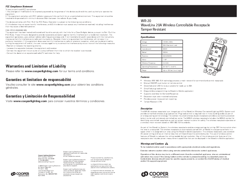
FCC Compliance Statement
To assure continued FCC compliance: 1. Any changes or modifications not expressly approved by the grantee of this device could void the user's authority to operate the equipment. 2. This equipment complies with FCC radiation exposure limits set forth for an uncontrolled environment. This equipment should be installed and operated with minimum distance 20cm between the radiator & your body.
This device complies with Part 15 of the FCC Rules. Operation is subject to the following two conditions: (1) this device may not cause harmful interference, and (2) this device must accept any interference received, including interference that may cause undesired operation.
CAN ICES-3 (B)/NMB-3(B) This equipment has been tested and tested and found to comply with the limits for a Class B digital device, pursuant to Part 15 of the FCC Rules. These limits are designed to provide reasonable protection against harmful interference in a residential installation. This equipment generates, uses and can radiate radio frequency energy and, if not installed and used in accordance with the instructions, may cause harmful interference to radio communications. However, there is no guarantee that interference will not occur in a particular installation. If this equipment does case harmful interference to radio or television reception, which can be determined by turning the equipment off and on, the user is encouraged to try to correct the interference by one or more of the following measures: - Reorient or relocate the receiving antenna. - Increase the separation between the equipment and receiver. - Connect the equipment into an outlet on a circuit different from that to which the receiver is connected. - Consult the dealer or an experienced radio/TV technician for help.
Warranties and Limitation of Liability
Please refer to www.cooperlighting.com for our terms and conditions.
Garanties et limitation de responsabilit�
Veuillez consulter le site www.cooperlighting.com pour obtenir les conditions g�n�rales.
Garant�as y Limitaci�n de Responsabilidad
Visite www.cooperlighting.com para conocer nuestros t�rminos y condiciones.

Cooper Lighting Solutions 1121 Highway 74 South Peachtree City, GA 30269 P: 770-486-4800 www.cooperlighting.com
� 2020 Cooper Lighting Solutions All Rights Reserved Printed in USA Imprim� aux �tats-Unis Impreso en los EE. UU. Publication No. IB503017EN April 2018

Cooper Lighting Solutions is a registered trademark. All trademarks are property of their respective owners.
Cooper Lighting Solutions est une marque de commerce d�pos�e. Toutes les autres marques de commerce sont la propri�t� de leur propri�taire respectif.
Cooper Lighting Solutions es una marca comercial registrada. Todas las marcas comerciales son propiedad de sus respectivos propietarios.

Product availability, specifications, and compliances are subject to change without notice.
La disponibilit� du produit, les sp�cifications et les conformit�s peuvent �tre modifi�es sans pr�avis.
La disponibilidad de productos, las especificaciones y los cumplimientos est�n sujetos a cambio sin previo aviso.

WR-20 WaveLinx 20A Wireless Controllable Receptacle Tamper Resistant

Specifications
Voltage Current Incandescent Ballast Resistive Motor Wireless Frequency Operating Temperature Range

125VAC, 60Hz 20A Maximum Load 960W 500VA 20A(2500W) 1 HP 2.4 GHz 32-104� F, 0-40� C Up to 100 feet line of sight

Features
� Wireless IEEE 802.15.4 technology creates a mesh network for command and control receptacle � Manual ON/OFF push button or remote control � Green/red color LED for status suitable for loads up to 20A � Simplified plug load control � Drag and drop programming via WaveLinx Mobile application � Supports overrides for Demand Response � Decorator style color matched wallplates � Provides power measurement reporting � Tamper-Resistant (TR)

Description
The WR-20 wireless receptacle is an integral part of the WaveLinx Wireless Connected Lighting (WCL) System and provides simplified wireless plug load control. Plug load control is required now in many building codes as part of an energy saving control strategy. The wallbox mounted wireless duplex receptacle provides a constantly powered bottom outlet and a wirelessly controlled top outlet. The NEMA wireless receptacle includes the NEMA symbol for identifying a controlled receptacle as well as tamper resistant outlets for safety. The wireless receptacle operates on a wireless mesh network based on IEEE 802.15.4 standards.
As part of the WaveLinx System, the wireless receptacle enables energy savings by turning OFF the top outlet when the area is unoccupied. The wireless receptacle is automatically paired with all WaveLinx occupancy sensors in a space when it is assigned to an area using the Wavelinx Mobile application. The wireless receptacle uses standard AC power wiring and has an internal relay that will Open/Close the controlled outlet. The use of wireless control features of WaveLinx reduces the wiring needed during installation. Use of the wireless control features of the receptacle also includes power measurement capabilities that can be displayed in the WaveLinx Mobile application.
Warnings and Cautions
To be installed and/or used in accordance with appropriate electrical codes and regulations.
Exercise extreme caution when using remote controllable devices to control appliances.
Operation of the device may be in a different room than the controlled appliance, also an unintentional activation may occur if the wrong button on the remote is pressed resulting in unwanted power on. Controllable devices should never be used to supply power to, or control the On/Off status of medical and/or life support equipment.

Dimensions

Installation Instructions

Wire Installation color guide Black - Line White - Neutral (N) Green - Ground (G)
Ground wire must be wrapped at least 2/3 to 3/4 around G terminal screw and tightened.

Strip conductor insulation 3/4" (20mm)
Tighten terminal screws to 14 lbf-in
Use only 12 AWG copper or copper clad wire with this device

3.79"
(96.50 mm)
3.26"
(83 mm)

1.68"
(42.79 mm)

1.96"
(50 mm)

Installation
This receptacle may be used in new installations or to replace an existing wall receptacle. Indoor use only.

WARNING:
TO AVOID FIRE, SHOCK ,OR DEATH ,TURN OFF THE POWER AT THE CIRCUIT BREAKER BEFORE INSTALLING THIS RECEPTACLE.

1. Warning!: Verify power is OFF before continuing.
2. For retrofit applications, remove wall plate.
3. Remove the existing receptacle from the box.
4. Disconnect the wiring from the existing receptacle.
5. Connect the receptacle as shown in the wiring diagram: Black lead to hot wire, white lead to neutral wire, green lead to ground wire.
6. Check connections to be sure they are tight and no bare conductors are exposed.
7. Insert the receptacle into the outlet box carefully.
8. Attach the receptacle to the box using supplied screws.
9. Attach the wall plate.
10. Restore power at the circuit breaker and test the system.

Wiring Diagram

Ground Green

Neutral White

Line Black

2

COOPER LIGHTING SOLUTIONS WaveLinx Wireless Controllable Receptacle Installation Instructions

Operations

Insulation strip 3/4" (20mm) in length.
Tighten terminal screws by turning clockwise. After tightening always test installed wires by pulling on them to show they are securely in place.

Either of the two "Line" and "N" terminal holes can be used during installation.
After stripping wire at 3/4" (20mm) in length fully insert wire and tighten.

Manual Switch Button

Wirelessly Controlled Receptacle
Red & Green LED Indicator

Always-on Receptacle
Basic Operation The controlled outlet can be turned ON in two ways: 1. Manually by switch button located on receptacle from plate. 2. Top receptacle controller wirelessly by the WaveLinx Wireless Area Controller (WAC).
This receptacle may be used in new installations or to replace an existing wall receptacle.

Manual Control
The switch button on receptacle allows user to:
1. Manually turn the connected equipment ON or OFF by short pressing the button. When the LED indicator turns off means controlled outlet is OFF. When the LED indicator turns green means controlled outlet is ON.
2. Manually put receptacle into pairing mode to Gateway by long pressing the button. When pairing mode is activated LED indicator will flash red. Please note when putting receptacle into pairing mode will also reset the receptacle.

COOPER LIGHTING SOLUTIONS WaveLinx Wireless Controllable Receptacle Installation Instructions 3