FX-PC Series Programmable Controllers and Related Products Product Bulletin
File info: application/pdf · 30 pages · 3.42MB
FX-PC Series Programmable Controllers and Related Products Product Bulletin
Code No. LIT-12011657
Code, No., LIT-12011657
FX-PC Series Programmable Controllers and Related ...
The Programmable Controller Family includes the FX-. PCG, FX-PCA, and FX-PCV Series Programmable Controller models. All the controllers run pre- ...
Extracted Text
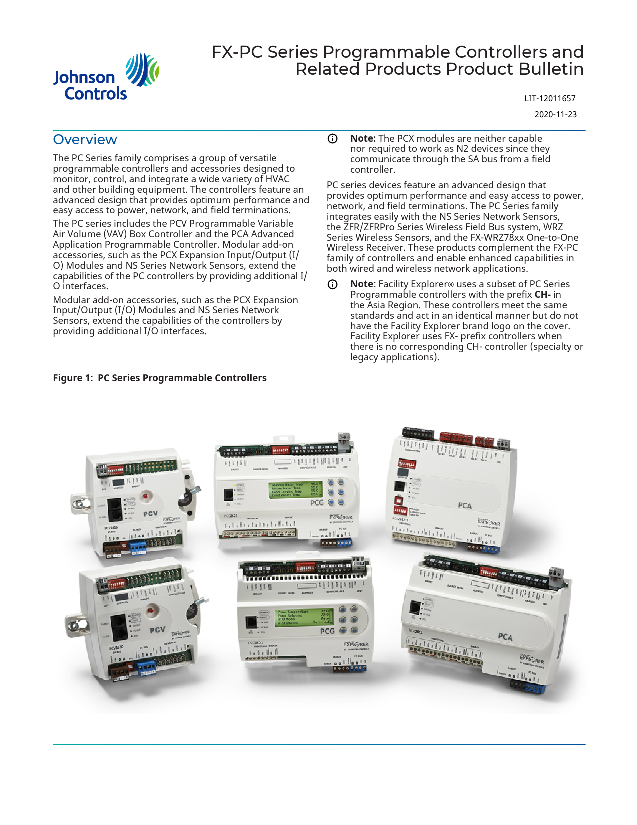
FX-PC Series Programmable Controllers and Related Products Product Bulletin

LIT-12011657 2020-11-23

Overview
The PC Series family comprises a group of versatile programmable controllers and accessories designed to monitor, control, and integrate a wide variety of HVAC and other building equipment. The controllers feature an advanced design that provides optimum performance and easy access to power, network, and field terminations. The PC series includes the PCV Programmable Variable Air Volume (VAV) Box Controller and the PCA Advanced Application Programmable Controller. Modular add-on accessories, such as the PCX Expansion Input/Output (I/ O) Modules and NS Series Network Sensors, extend the capabilities of the PC controllers by providing additional I/ O interfaces. Modular add-on accessories, such as the PCX Expansion Input/Output (I/O) Modules and NS Series Network Sensors, extend the capabilities of the controllers by providing additional I/O interfaces.
Figure 1:PC Series Programmable Controllers

Note: The PCX modules are neither capable nor required to work as N2 devices since they communicate through the SA bus from a field controller.
PC series devices feature an advanced design that provides optimum performance and easy access to power, network, and field terminations. The PC Series family integrates easily with the NS Series Network Sensors, the ZFR/ZFRPro Series Wireless Field Bus system, WRZ Series Wireless Sensors, and the FX-WRZ78xx One-to-One Wireless Receiver. These products complement the FX-PC family of controllers and enable enhanced capabilities in both wired and wireless network applications.
Note: Facility Explorer� uses a subset of PC Series Programmable controllers with the prefix CH- in the Asia Region. These controllers meet the same standards and act in an identical manner but do not have the Facility Explorer brand logo on the cover. Facility Explorer uses FX- prefix controllers when there is no corresponding CH- controller (specialty or legacy applications).

Features and benefits
Standard BACnet Protocol
Provides interoperability with Johnson Controls and thirdparty BAS products that use the widely accepted BACnet standard.
Standard Hardware and Software Platform
Uses a common hardware design throughout the family line to support standardized wiring practices and installation workflows. Also uses a common software design to support the use of a single tool for control applications, commissioning, and troubleshooting to minimize technical training
Models to support communication protocols that are switchable between BACnet MSTP and N2
At CCT Release 10.1, a new capability allows controllers to be configured to communicate using either the BACnet MSTP or the N2 field bus networking protocol. The operation of the PCX is not affected by the selection of the BACnet MSTP or the N2 protocol in the host controller.
Models to support BACnet/IP communications

Auto-Tuned Control Loops
Reduce commissioning time, eliminate change-ofseason re-commissioning, and reduce wear and tear on mechanical devices.
Universal Inputs, Configurable Outputs, and Point Expansion Modules
Allow multiple signal options to provide input/output flexibility.
Optional Local User Interface Display
Allows convenient monitoring and adjusting capabilities at the local device.
BACnet Testing LaboratoriesTM (BTL) Listing
Ensures interoperability with other BTL-listed devices. BTL is a third-party agency that validates BAS vendor products meet the BACnet industry-standard protocol.

The PCA4911 and the PCV1930 communicate over the BACnet/IP protocol. This allows more flexibility in choosing the devices for your site's network.

Figure 2:Facility Explorer System with PC Controllers Network diagram with Controllers

2

FX-PC Series Programmable Controllers and Related Products Product Bulletin

Integration to FX Supervisory
Controllers
PC series devices are designed to integrate seamlessly into the FX system by connecting and communicating directly with FX Supervisory Controllers. This seamless integration enables building operators to monitor and adjust the controllers directly from the FX system UI.
In addition, service personnel can view the controller information locally through the integral LCD (included on some FX-PCG models), through an optional local controller display (FX-DIS1710-0) available for field controllers or through the optional Mobile Access Portal (MAP) Gateway.
Controller Configuration Tool (CCT)
The CCT is used to configure, simulate, and commission the PCA family of controllers.
Configuration mode allows you to select a number of mechanical and control logic options through System Selection Trees for typical air handling, terminal unit, VAV box, and central plant mechanical systems. When required, you can customize the standard logic provided by the system selection process to meet your specialized control logic requirements. Configuration mode also allows you to customize certain display options available to PC Controllers that use a local controller display.
Figure 3:Mechanical selection in CCT

Note: Ethernet Passthru is not available on controllers configured for N2 communications.
After downloading the controllers, you can use the CCT Commissioning mode to validate the sensor and control point interfaces and adjust key setpoints and setup parameters (Figure 4).
CCT includes integrated productivity features with utilities to facilitate mass application uploads and downloads, including upgrades of entire trunks of controllers with just a few mouse clicks. Template files provide an intuitive method of reading and writing configuration parameters to multiple controllers, reducing the time it takes to commission your field controller networks.
For VAV applications, CCT features an optional box flow test to automatically exercise all the VAV boxes to ensure correct mechanical installation and proper configuration of the key flow setup parameters. Additionally, the Facility Explorer system provides multiple configurations of room network sensors and a handheld VAV balancing tool that can be used to perform VAV balancing tasks.
In addition, the Commissioning wizard has a Balancer tab for VAV applications to easily auto-calibrate VAV boxes and set flow constants in one location.
A Commissioning-mode-only version of the CCT software is available to the Johnson Controls branch offices for jobs or individuals that require only commissioning tasks (for example, balancing contractors). The Configuration and Simulation modes are disabled in the CCT Commissioning software.
Figure 4:CCT user interface

Simulation mode allows you to review, run, or simulate the application logic as if you were commissioning a live system. You can make adjustments to setpoints, inputs, or sensors during a simulation session to validate the logic before assigning the configuration to a specific controller.
Commissioning mode manages the downloading of files to the field equipment controllers through multiple network connection points. You can connect using the MAP Gateway or by using the Ethernet Passthru mode in conjunction with the SCT through a FX Supervisory Controller.

Features
� Capability to customize standard control system logic that is created from simple system selection trees.
� Consistent user interface across the Configuration, Simulation, and Commissioning modes.
� Flexible connection capabilities for loading and commissioning controllers.

FX-PC Series Programmable Controllers and Related Products Product Bulletin

3

PC Series Programmable Controllers
and Expansion Modules Family
The Programmable Controller Family includes the FXPCG, FX-PCA, and FX-PCV Series Programmable Controller models. All the controllers run pre-engineered or userprogrammed applications and provide the I/O required to monitor and control a wide variety of HVAC equipment.
This family of diverse programmable controllers is designed to install easily and communicate through standard BACnet MS/TP , N2, or wireless protocols enabling you to build an almost endless variety of field controller network applications, ranging from simple fan coil, heat pump, or VAV control applications to very advanced central plant management and stand-alone applications.
Important: Some CH-PC controllers are also compatible with the FX system. Refer to PC Series Programmable Controllers and Related Products for use with FX in the Asia Region Product Bulletin (LIT-12013279) for further details.
FX-PC Controller features
Features and benefits common to the PC series family devices include the following:
� 32-bit microprocessor ensures optimum performance and meets industry specifications.
� BACnet MS/TP Protocol supports seamless integration into Johnson Controls and third-party BACnet devices.
� MS/TP Field Controllers have an integral end-ofline (EOL) switch that enables field controllers to be terminating devices on the communications bus.
� Pluggable communications bus and supply power terminal blocks expedite installation and troubleshooting.
� MS/TP controllers have wireless connectivity through the ZFRPro Series Wireless Field Bus Systems that enables wireless mesh connectivity to supervisory controllers, facilitating easy initial location and relocation
� Writable flash memory allows standard or customized applications to be downloaded from CCT and enables persistent application data.
� Local UI display provides enhanced local monitoring
� User-friendly graphic theme and clear pushbutton identification facilitate easy navigation of the integral or optional UI/display
� Patented technologies including Proportional Varying Deadzone Control (PVDC), Pattern Recognition Adaptive Control (PRAC+), and Pulse Modulation Adaptive Control (PMAC) provide continuous loop tuning.
� Large product family provides a wide range of point mix to meet application requirements and allows for the addition of one or more PCXs or NS Series Network Sensors to provide even more I/O capacity.
Communications protocols
The Modernization Guide for Legacy N2 Controllers (LIT-12012005) and the controller-specific documentation provide installation and commissioning support including

tips for efficient and safe replacement. For information about mapping N2 Objects in controllers with switchable communications protocols, refer to the N2 Compatibility Options chapter of the Controller Tool Help (LIT-12011147).
The FX-PC Family Controllers and network sensors communicate using the standard BACnet protocol, based on the ANSI/ASHRAE 135-2016. The BACnet protocol is a standard for ANSI, ASHRAE, and the International Standards Organization (ISO) for building controls.
PCG, PCX, and PCV devices are BTL-listed as BACnet Application Specific Controllers (B-ASCs). The PCA controllers and the PCV1930 controller are BTL-listed as BACnet Advanced Application Controllers (B-AACs). The NS Series Sensors are BTL-listed as BACnet Smart Sensors (B-SSs).
Release 10.1 of the Controller Configuration Tool (CCT) 13.0 and later can be used to switch the Field Bus communications protocol in supported controllers to be either the standard BACnet MS/TP or the N2 protocol. All new controllers use either BACnet MS/TP as the default communications protocol, or BACnet/IP. Switchable communications protocols in the MS/TP models provide a cost-effective upgrade and modernization path for customers with existing N2 controllers.
The Modernization Guide for Legacy N2 Controllers (LIT-12012045) and the controller-specific documentation provide installation and commissioning support and include tips for efficient and safe replacement. Refer to the N2 Compatibility Options chapter of the Controller Tool Help (LIT-12011147) for information about mapping N2 Objects in controllers with switchable communications protocols.
The N2-capable FX-PC Controllers can be used as functional replacements for legacy N2 controllers. The N2capable FX-PC Controllers:
� have the I/O quantities and characteristics of the FX-PC family controllers
� must be programmed with CCT, which have programming capabilities that are similar (but not identical) to HVACPro, GX9100, GPL, and other legacy tools
� support SA Bus devices
� support WRZ wireless sensors from the controller using the FX-WRZ7860 receiver when configured for BACnet MS/TP communication
The N2-capable FX-PC controllers:
� do not support Zone Bus (for example, TMZ sensors and M100 actuators)
� do not support passthrough in the commissioning mode
� do not support remote downloading or commissioning using BACnet routing
� do not support wireless connection to the N2 bus
Hardware and installation
FX-PC controllers are encased in a durable, plenumrated, plastic housing. The plastic housing may eliminate the need for a separate enclosure for plenum-rated construction. Check regional, national, and local code requirements for appropriate applications. FX-PC controllers feature bright, color-coded LEDs, visible on

4

FX-PC Series Programmable Controllers and Related Products Product Bulletin

the controller cover, that indicate the supply power, communications bus, and EOL switch status, as well as a variety of fault conditions to aid troubleshooting the controller and bus.
An integral EOL switch on each MS/TP controller allows you to enable the controller as a bus terminating device, which when properly configured, reduces reflected noise on the bus and improves bus communication.
Each MS/TP controller has an easily accessible, eightposition DIP switch that allows you to set a valid and unique device address for each controller on the bus. A blank space is included on the controller cover for recording the device address.
The BACnet/IP field controllers feature rotary switches to give each controller a unique number on the subnet where it resides, to identify it in CCT for uploading, downloading, and commissioning.
The controllers feature removable, color-coded, keyed, and labelled terminal block plugs for the supply power and communications bus terminations. Most models have fixed, color-coded, and labelled terminal blocks for the input and output terminations, which facilitate installing and servicing the controllers.
The I/O terminations on the models are spade lugs. Pluggable screw terminal blocks that connect to the I/O spade terminations are also available as optional accessories.FX-PCA2612 models have removable, colorcoded, and labelled terminal block plugs for the I/O terminations.
The controllers have iintegral mounting clips and a DIN rail track on the back-plate that allows you to easily mount the controller either on a horizontal section of 35 mm DIN rail or directly to a wall or flat vertical surface.Some PCG models have a backlit user interface display with adjustable brightness and contrast to ensure readability in low-light environments. The easy-to-use display provides convenient local monitoring and adjusting of key setpoints and control parameters. For the PCG and PCA models without a display, a stand-alone FX-DIS1710 Local Controller Display module is available that connects directly to the SA Bus port. For details, refer to the FX-DIS Local Controller Display Product Bulletin (LIT-12011667).

PCG General Purpose Programmable
Controllers
You can switch PCG programmable controllers between BACnet MS/TP and N2 Communications protocols. When they are used as BACnet MS/TP devices, they are a BACnet Application Specific Controller (B-ASC) with integral MS/ TP communications. In N2 mode, they can be used to modernize sites with legacy Johnson Controls controllers.
These controllers run pre-engineered and userprogrammed applications and provide the inputs and outputs required to monitor and control a wide variety of HVAC equipment.
The full range of PCG models combined with the PCX expansion modules can be applied to a wide variety of building applications ranging from simple fan coil or heat pump control to advanced central plant management. All PCG Series Controllers configured for BACnet support wireless communications using the ZFR/ZFR Pro System accessories.
Features
� Pluggable communications bus and supply power terminal blocks expedite installation and troubleshooting.
� Integral EOL switch enables field controller as a terminating device on the communications bus.
� Pluggable communications bus and supply power terminal blocks expedite installation and troubleshooting.
� Patented proportional adaptive control (P-Adaptive) and Pattern Recognition Adaptive Control (PRAC) technologies provide continuous loop tuning.
� Writable flash memory allows standard or customized applications to be downloaded from CCT and enables persistent application data.
� Large product family provides a wide range of point mix to meet application requirements and allows for the addition of one or more PCXs and/or Network Sensors to provide even more I/O capacity.
PCG Controller Series point type counts
per model

Table 1: PCG Series point type counts per model

Point types

Signals accepted

PCG16xx

Universal Input (UI)

Analog Input, Voltage Mode, 0�10 VDC Analog Input, Current Mode, 4�20 mA Analog Input, Resistive Mode, 0�2k ohm, RTD (1k NI [Johnson Controls], 2 1k PT, A99B SI), NTC (10k Type L, 2.252k Type 2) Binary Input, Dry Contact Maintained Mode

PCG25xx

PCG26xx

4 (Does not support Current Mode)

6

Dry Contact Maintained Mode

Binary Input (BI) Pulse Counter/Accumulator Mode 1

6

2

(High Speed), 100 Hz

FX-PC Series Programmable Controllers and Related Products Product Bulletin

5

Table 1: PCG Series point type counts per model

Point types

Signals accepted

Analog Output (AO)

Analog Output, Voltage Mode, 0�10 VDC
Analog Output, Current Mode, 4�20 mA

Binary Output (BO) 24 VAC Triac

Configurable Output (CO)

Analog Output, Voltage Mode, 0�10 VDC
Binary Output Mode, 24 VAC Triac

PCG16xx
3 4

PCG25xx

PCG26xx

2 (Voltage Only)

2

2 (Ext Power Only) 3

2

4

Note: Analog Input, Current Mode is set by hardware for the FX-PCG26xx, and by software for the FX-PCG25xx.
PCA Programmable Controllers
PCA Series Controllers are programmable controllers that can communicate using BACnet/IP, MS/TP, or N2 communications protocols, depending on the model. The PCA4911 Series controller communicates using BACnet/IP communications protocol, and is a BACnet Advanced Application Controller (B-AAC). The other PCA Series controllers can be switched between MS/TP and N2 Communications protocols and when used as MS/TP devices are BACnet Advanced Application Controllers (BAACs).
PCA Series controllers feature an integral real-time clock and support time-based tasks, which together enable these field controllers to monitor and control schedules, calendars, alarms, and trends. PCAs can continue timebased control and monitoring when offline for extended periods of time from a system network. The PCAs include RS-485 field bus networking with BACnet MS/TP protocols.
PCA controllers can be combined with PCX Expansion I/ O Modules to gain more I/O interfaces, if needed. PCAs and their advanced features make them well suited for monitoring and controlling a wide range of more complex equipment (such as airhandlers and central plants).
PCA Series controllers can also operate as stand-alone controllers in applications that do not require a networked supervisory device or for network applications where it is preferred to have the scheduling, alarming, and/or trending performed locally in the field controllers.
The PCA2513 and PCA3613 are programmable controllers. They are BACnet Application Specific Controllers (B-ASC) with integral MS/TP communications. These controllers run pre-engineered and user-programmed applications and provide the inputs and outputs required to monitor and control a wide variety of HVAC equipment. A PCA2513 or PCA3613 controller combined with the PCX models can be applied to a wide variety of building applications ranging from simple fan coil or heat pump control to advanced central plant management.
PCA2612 controller models feature line-voltage relay outputs, making these controllers well suited for use in terminal units. The PCA2612-2 model uses a linevoltage power supply, eliminating the need for a 24 VAC transformer in line-voltage applications.

Features
In addition to the features and benefits listed in FX-PC Controller features, PCAs also provide:
� Support for the FX-DIS17 remote display for monitoring and commanding of I/O and configuration parameters
� onboard real-time clock and time-based control logic, such as scheduling, alarming, and trending
� line voltage relays (FX-PCA2612 models)
� line voltage power supply (FX-PCA2612-2)
PCV Programmable VAV Box
Controller Series
PCVs are programmable digital controllers tailored for VAV applications that can be switched between MS/ TP and N2 Communications protocols. When they are used as MS/TP devices, they communicate through the BACnet� MS/TP protocol. In N2 mode, they can be used as replacements for legacy Johnson Controls� controllers.
The PCV controllers feature an integral digital differential pressure transducer (DPT), an integral damper actuator, and a 32-bit microprocessor. The controllers' small package size facilitates quick field installation and efficient use of space, while not compromising high-tech control performance. These controllers easily adapt NS Series Network Sensors for zone and discharge air temperature sensing.
The PCV1930 programmable controller uses BACnet/ IP networking for higher speed communication with the Controller Configuration Tool (CCT) and improved bandwidth. This gives you more flexibility in choosing controllers for your site's specific needs.
The PCV18 models are designed to be functional replacements for the VMA14xx Series Variable Air Volume Modular Assembly Controllers. They contain a sensor bus port and accessories well suited for replacing VMA14xx Controllers.
The PCV1626 Controller is shipped with an actuator but without a differential pressure transducer (DPT), making the controller well suited for commercial zoning applications or for pressure-dependent VAV box applications where no DPT is required. The PCV1656 controller is shipped without a differential pressure transducer but with an integrated actuator and ball valve linkage. This controller is for use on the Johnson Controls VG-1000 1/2 to 1 inch valves and needs to be used primarily as a replacement for the assembly of the

6

FX-PC Series Programmable Controllers and Related Products Product Bulletin

VG-1000 Series Smart Valve product. The smart valve product line is ideal for chilled beam applications. The PCV1628 includes a DPT but does not have an actuator. Without an actuator, this controller is well suited for controlling large VAV boxes that require more than 4 N�m of torque.
These features make the PCV16 controllers the product of choice for VAV systems. The wide variety of network sensor models provides options for measuring and displaying zone temperature, occupancy detection, duct temperature, zone humidity and dewpoint determination, carbon dioxide (CO2) level, setpoint adjustments, VAV box fan speed control, and discharge air temperatures.
Features
In addition to the features and benefits listed in FX-PC Controller features, FX-PCVs provide the following:
� Three universal inputs that allow an increased number of low cost sensor options.
� A state-of-the-art, digital non-flow pressure sensor to provide 14-bit resolution with bidirectional flow operation that supports automatic correction for polarity on high- and low-pressure DP tube connections. This pressure sensor eliminates high- and low-pressure connection mistakes.
� A phone jack-style connector on the FC Bus and SA Bus to support quick connection to the FX-BTCVT Bluetooth Commissioning Converter, FX-ZFR or FX-ZFR Pro Series wireless router, and network sensors.
� Models that include actuators feature a fast response actuator that drives the damper from full open to full closed (90�) in 60 seconds to reduce commissioning time.
� ZigBee� Wireless FC/SA Bus Interface to provide a wireless alternative to hard-wired FX systems (where available), while providing application flexibility, mobility, and minimal disruption to building systems.

FX-PC Series Programmable Controllers and Related Products Product Bulletin

7

PCV Series point type counts per model

Table 2: PCV16 and PCV19 Series point type counts per model

PCV 1615 PCV1617 PCV 1626 PCV 1628 PCV1632 PCV 1656 PCV 1930

Communication Protocol Modular Jacks

BACnet MS/TP, N2

BACnet/IP

6-pin SA Bus with four communicating sensors and 6-pin FC Bus for tool support

6-pin FC Bus for tool support

Point Types

Signals Accepted

Analog Input, Voltage Mode, 0�10 VDC

Analog Input, Resistive

Mode, 0�2k ohm, RTD (1k

Universal Input (UI) NI [Johnson Controls], 1k 3

3

3

3

3

3

3

PT, A998 SI), NTC (10k Type

L, 2.252k Type 2)

Binary Input, Dry Contact

Maintained Mode

Binary Output (BO) 24 VAC Triac

2

2

3

3

3

3

3

Analog Output, Voltage

Configurable Output Mode, 0�10 VDC

(CO)

Binary Output Mode, 24

2

2

2

2

2

VAC Triac

1 with

Integrated Actuator Internal

1

1

1

1

1

ball valve 1

linkage

Integrated Flow Sensor

Internal

1

1

1

1

1

Zone Sensor Input On SA Bus 1

Up to 4 NS Series Network Zone Sensors Up to 9 WRZ sensors when using the ZFR/ZFR Pro Series wireless router configuration

1 A total of 10 MS/TP master addresses (PCXs), not including sensor addresses (MS/TP), can be used in a single PCV controller.

Table 3: PCV18 Series point type counts per model

Point types

Signals accepted

Modular Jacks

Universal Input (UI)
Binary Output (BO) Configurable Output (CO) Integrated Actuator Differential Pressure Transducerb

Analog Input, Voltage Mode, 0�10 VDC Analog Input, Resistive Mode, 0�2k ohm, RTD (1k NI [Johnson Controls], 1k PT, A998 SI), NTC (10k Type L, 2.252k Type 2) Binary Input, Dry Contact Maintained Mode 24 VAC Triac Analog Output, Voltage Mode, 0�10 VDC Binary Output Mode, 24 VAC Triac Internal
Internal

PCV1826

PCV1832

8-pin SA Bus supports analog non-

communicating sensor

3

3

3

3

2

2

1

1

1

Up to 4 NS Series Network Zone Sensors

Zone Sensor Input On SA Bus1

Up to 9 WRZ sensors when using the ZFR/ ZFRPro Series wireless router configuration and

up to 5 WRZ sensors when using the one-to-

one wireless configuration

1 A total of 10 MS/TP master addresses (PCXs), not including sensor addresses (MS/TP), can be used in a single PCV controller.

8

FX-PC Series Programmable Controllers and Related Products Product Bulletin

PCX Expansion Input/Output Module
The PCXs are expansion I/O modules with integral RS-485 MS/TP communications.
Note: At Controller Configuration Tool (CCT) 13.0 or later, using 10.1 Release Mode, the PCGs, PCAs, and PCVs can communicate by using either the BACnet or the N2 field bus networking protocol. The operation of the PCX is not affected by the selection of the BACnet or the N2 protocol in the host controller.
PCXs can serve in one of two capacities, depending on where they are installed in the control system. When installed on the Sensor Actuator (SA) Bus of PCA controllers, the PCXs expand the I/O interfaces of the controllers. When installed on the Field Controller (FC)
Table 4: FX-PCX Series point type counts per model

Bus, PCXs can be used as I/O point multiplexors to support monitoring and control from a supervisory controller. The point multiplexor can also be useful for sharing points between other PC controllers on the FC Bus using peer-to-peer connectivity.
A full range of PCA models combined with the PCX models can be applied to a wide variety of building applications ranging from simple fan coil or heat pump control to advanced central plant management.
Features
In addition to the features and benefits listed in FX-PC Controller features, PCXs provide the ability to reside on the FC Bus or SA Bus to provide application flexibility.
PCX Series point type counts per model

Point types Signals accepted FX-PCX 1711 FX-PCX 2711 FX-PCX 2721 FX-PCX 3711 FX-PCX 3721 FX-PCX 3731 FX-PCX 4711

Analog Input, Voltage Mode, 0�10 VDC

Analog Input, Current Mode, 4�20 mA

Universal Input Analog Input, Resistive Mode, 0�2k ohm, RTD

(UI)

(1k NI [Johnson Controls], 1k PT, A99B SI), NTC

2

8

4

6

(10k Type L, 2.252k Type 2)

Binary Input, Dry Contact Maintained Mode

Dry Contact Maintained Mode

Binary Input (BI)

Pulse Counter/Accumulator Mode (High

4

Speed), 100 Hz

16

8

2

Analog Output Analog Output, Voltage Mode, 0�10 VDC

(AO)

Analog Output, Current Mode, 4�20 mA

2

2

Binary Output (BO)

24 VAC Triac

8

3

Analog Output, Voltage Mode, 0�10 VDC

Universal Output (UO)

Binary Output Mode, 24 VAC/DC FET

2

4

Analog Output, Current Mode, 4�20 mA

Configurable Output (CO)

Analog Output, Voltage Mode, 0�10 VDC Binary Output Mode, 24 VAC Triac

4

Relay Output (RO) (-0 Models 120/240 VAC Only)

2

4

Relay Output (RO) (-2 Models 24 VAC Only)

2

4

FX-PC Series Programmable Controllers and Related Products Product Bulletin

9

Table 5: PCX Series point type counts per model

Point types
Universal Input (UI)
Binary Input (BI) Analog Output (AO) Binary Output (BO)

Signals accepted Analog Input, Voltage Mode, 0�10 VDC Analog Input, Current Mode, 4�20 mA Analog Input, Resistive Mode, 0�2k ohm, RTD (1k NI [Johnson Controls], 1k PT, A99B SI), NTC (10k Type L, 2.252k Type 2) Binary Input, Dry Contact Maintained Mode Dry Contact Maintained Mode Pulse Counter/Accumulator Mode (High Speed), 100 Hz Analog Output, Voltage Mode, 0�10 VDC Analog Output, Current Mode, 4�20 mA
24 VAC Triac (Ext Power Only)

PCX 2723 8
2

PCX 3723 16

PCX 3733
8 8

Panel and Sub-Panel Assembly
Options
The controllers are also available in pre-wired panels and sub-panel assemblies. The panelized controller options provide all of the controllers necessary for a complete application solution, including a pre-wired power source and a latching or lockable door.
Note: FX-PC controllers in pre-built panels and subpanel assemblies are available for purchase only in North America.
Mobile Access Portal (MAP) Gateway
The MAP Gateway is a pocket-sized web server that provides a wireless mobile user interface to SMART Equipment and Johnson Controls branded system controllers and thermostats. Small, lightweight, and easy to use, the MAP Gateway joins the rapidly expanding list of Johnson Controls products that leverage the power of mobility and smart devices to improve daily operations.
The MAP Gateway can be used to access field bus devices on Facility Explorer systems and SMART Equipment rooftop units (RTUs) with unit control boards (UCBs). The MAP Gateway supports Johnson Controls branded Field Controllers, including PCA, PCG, and PCV Series devices. It also supports the TEC3000 Series Thermostats. Offering many-to-one, multi-client connectivity, the MAP Gateway provides access to any SMART Equipment device that is on a connected BACnet MS/TP field bus. The MAP Gateway solution is conveniently sized and has a built-in wireless access point. The MAP Gateway provides an intuitive, browser-based user interface to access advanced features like alarms and point configuration.
The MAP Gateway at Release 4.2 can be used to commission the BACnet/IP field controllers, the PCA4911 and PCV1930, when directly connected to them using their SA bus sensor port or through a thermostat connected on the same port.
For more information on the MAP Gateway, refer to the Mobile Access Portal Gateway Product Bulletin (LIT-12011884).

Figure 5:Mobile Access Portal
Handheld VAV Box Balancing Tool (FX-ATV7003)
The Handheld VAV Box Balancing Tool (FX-ATV7003) lets you set the parameters for VAV box applications that reside on the controllers. The VAV box balancing parameters appear on the tool's LCD. A dial and two buttons let you navigate through intuitive menus to balance the VAV box. The menus are

10 FX-PC Series Programmable Controllers and Related Products Product Bulletin

customized to the type of application that resides in the controller. The balancing operation features an adjustable time-out parameter that returns the tool and controller to normal operation if you leave the controller in balancing mode. The Handheld VAV Box Balancing Tool is lightweight and portable. It can plug into any model of network sensor to access the VAV box controller. The Handheld VAV Box Balancing Tool is compatible with the following devices: � PCV loaded with a VAV application � PCG or PCA loaded with a VAV application � NS Series Network Sensor connected to an PCV, PCG, or
PCA loaded with a VAV box application
Figure 6:Handheld VAV Box Balancing Tool
Network Sensors
The NS Series Network Sensor offering includes NS Series Network Zone Sensors and NS Series Network Discharge Air Sensors, see Figure 7.
Features
The Handheld VAV Box Balancing Tool provides the following features: � Allows VAV box balancing and commissioning
without a laptop. � Connects directly to the controller or the controller
NS Series Network Sensor through standard RJ-12 plug. � Intuitive, menu-driven operation simplifies balancing tasks.
FX-PC Series Programmable Controllers and Related Products Product Bulletin 11

Figure 7:Network Zone Sensors and Discharge Air Sensors

The NS Series Network Zone Sensors are designed to function directly with the controllers. Several models of network zone sensors monitor room temperature. Options are available to also monitor zone humidity, carbon dioxide (CO2), occupancy local temperature setpoint adjustments, and other variables. This data is transmitted to a controller on the SA Bus.
The NS Series Network Zone Sensors include models with a temperature setpoint dial and LCD that allows occupants to view the zone temperature and view and adjust the zone temperature setpoint. A fan mode pushbutton is included to set the desired fan speed (AUTO-OFF-low-medium-high). An occupancy override function allows the user to signal the controller that the zone is occupied to override the scheduled mode. Some models have DIP switches to set a unique address for applications that require multiple sensors.
For communication wiring flexibility, the wires connecting the network zone sensor to a controller can be terminated using a modular jack or screw terminals.
Each network zone sensor includes an SA Bus access port to allow accessories to access the SA Bus. This plug allows accessories to service or commission the connected controller or gain access to any other controller on the same FC Bus.
The NS Series Network Discharge Air Sensors are electronic duct sensors designed to function directly with the controllers. Models in this series monitor the

duct temperature, typically at the discharge of the VAV box, and transmit this data to a controller on the SA Bus using the 305 cm (10 ft) wiring lead included with the unit. The 305 cm (10 ft) wiring lead consists of four 22 AWG trade size color-coded wires encased in a plenum-rated jacket. Each of the wires is stripped and tinned for easy connection to the SA Bus screw terminal block.
The NS Series Network Discharge Air Sensors are available with either a 102 or 203 mm (4 or 8 in.) temperature probe. All models include DIP switches for applications requiring multiple discharge air sensors, each with a unique DIP switch address.
When using the FX-PC18 as a replacement for an existing VMA1400, note the following:
� FX-PCV18 is able to reuse existing TE-6xxx Series sensors.
� FX-PCV18 is able to reuse existing TE-700 Series sensors.
� FX-PCV18 is able to reuse existing TE-730 Series sensors.
� FX-PCV18 is not able to reuse existing TMZ1600 Series sensors and requires replacement of the TMZ with a new sensor.
� FX-PCV18 can be used with the NS Series Network sensors.

12 FX-PC Series Programmable Controllers and Related Products Product Bulletin

� FX-PCV18 can be used with the WRZ Series wireless sensors and the WRZ78xx Series One-to-One wireless receiver.
Refer to the NS Series Network Sensors Product Bulletin (LIT-12011574) for important product application information, ordering information, and technical specifications.
FX-PC Series Programmable Controllers and Related Products Product Bulletin 13

PCA Series ordering information

Table 6: FX-PCA Series ordering information

Product code number CH-PCA2513-0 FX-PCA2611-0 FX-PCA2612-1 FX-PCA2612-2 CH-PCA3613-0 CH-PCA4911-0

Description 16-Point Advanced Application Programmable Controller with 4 UI, 6 BI, 2 AO, 2 BO, and 2 CO; 24 VAC; FC and SA Bus Support; Integral Real-time Clock. 17-Point Advanced Application Programmable Controller with 6 UI, 2 BI, 4 CO, 3 BO, and 2 AO; 24 VAC; SA Bus; FC Bus; Integral Real-time Clock 18-Point Advanced Application Programmable Controller with 5 UI, 4 BI, 4 CO, 2 SPDT RO, and 3 SPST RO; 24 VAC; SA Bus; FC Bus; Integral Real-time Clock 18-Point Advanced Application Programmable Controller with 5 UI, 4 BI, 4 CO, 2 SPDT RO, and 3 SPST RO; 100�240 VAC; SA Bus; FC Bus; Integral Real-time Clock 26-Point Advanced Application Programmable Controller with 8 UI, 6 BI, 6 BO, and 6 AO; 24 VAC; SA Bus; FC Bus; Integral Real-time Clock; Improved Fast Persistence. 28-Point Advanced Application Programmable Controller with 10 UI, 6 BI, 4 BO, 4 AO, and 4 CO; 24 VAC; SA Sensor Port; Integral Real-time Clock; 2 Ethernet Ports for BACnet/IP Communications

PCG Series ordering information

Table 7: PCG Series ordering information

Product Code Number Description

FX-PCG1611-1

0-Point General Purpose Programmable Controller with 2 UI, 1 BI, 3 BO, and 4 CO; 24 VAC; FC and SA Bus Support

FX-PCG1611-1ET

FX-PCG1611 Extended Temperature controller for rooftop applications. Supports Operational Temperature Range of -40�C to 70�C (-40�F to 158�F).

FX-PCG1621-1

10-Point General Purpose Programmable Controller with 2 UI, 1 BI, 3 BO, and 4 CO; 24 VAC; FC and SA Bus Support; Integral Display with Pushbutton User Interface

FX-PCG2611-0

17-Point General Purpose Programmable Controller with 6 UI, 2 BI, 3 BO, 2 AO, and 4 CO; 24 VAC; FC and SA Bus Support

FX-PCG2611-0ET

FX-PCG2611 Extended Temperature controller for rooftop applications. Supports Operational Temperature Range of -40�C to 70�C (-40�F to 158�F).

FX-PCG2621-0

17-Point General Purpose Programmable Controller with 6 UI, 2 BI, 3 BO, 2 AO, and 4 CO; 24 VAC; FC and SA Bus Support; Integral Display and Pushbutton User Interface

PCV Series ordering information

Table 8: PCV Series ordering information

Product code number FX-PCV1615-1 CH-PCV1617-0 FX-PCV1626-1 FX-PCV1628-1 FX-PCV1630-1 FX-PCV1630-1G
CH-PCV1632-0
FX-PCV1656-1

Description 32-bit, Integrated VAV Controller/Actuator/DPT, 3 UI and 2 BO; 24 VAC; FC Bus, and SA Bus 32-bit, integrated VAV controller/Actuator/DPT, 3 UI and 2 BO; 24 VAC; FC Bus, and SA Bus, includes 8-pin TSTAT Port for use with TE-7xx Series Non-Communicating Sensors. 32-bit, Integrated VAV Controller and Actuator, 3 UI, 3 BO, and 2 CO; 24 VAC; FC Bus, and SA Bus (No DPT) 32-bit, Integrated VAV Controller and DPT, 3 UI, 3 BO, and 2 CO; 24 VAC; FC Bus, and SA Bus (No Actuator) 32-bit, Integrated VAV Controller/Actuator/DPT, 3 UI, 3 BO, and 2 CO; 24 VAC; FC Bus, and SA Bus Buy American. Integrated VAV Box Controller, Actuator and Pressure Sensor: 3 UI, 3 BO and 2 CO, 24 VAC; FC and SA Bus, non-isolated power supply 32-bit, Integrated VAV Controller/Actuator/DPT, 3 UI, 3 BO, and 2 CO; 24 VAC; FC Bus, and SA Bus, Includes 8-pin TSTAT Port for use with TE-7xx Series Non-Communicating Sensors. 32-bit, Integrated VAV Controller and Actuator, 3 UI, 3 BO, and 2 CO; 24 VAC; FC Bus, and SA Bus, Integrated Ball Valve Linkage

FX-PC Series Programmable Controllers and Related Products Product Bulletin 15

Table 8: PCV Series ordering information

Product code number FX-PCV1826-1
FX-PCV1832-1 CH-PCV1930-0

Description
32-bit, Integrated VAV Controller and Actuator, 3 UI, 3 BO, and 2 CO; 24 VAC; FC Bus, and SA Bus; Includes cable adapters for use when replacing VMA14xx Series controllers. Recommended replacement for VMA1440 controller (No DPT) 32-bit, Integrated VAV Controller/Actuator/DPT, 3 UI and 2 BO; 24 VAC; FC Bus, and SA Bus includes cable adapters for use when replacing VMA14xx Series controllers. Recommended replacement for VMA1410, VMA1415, or VMA1420 controller. 32-bit, Integrated VAV Controller/Actuator/DPT, 3 UI, 3 BO, and 2 CO; 24 VAC; and SA Sensor Port; Integral Real-time Clock; 2 Ethernet Ports for BACnet/IP Network Communications

PCX Series ordering information

Table 9: FX-PCX Series ordering information

Product code number FX-PCX1711-0 FX-PCX2711-0
FX-PCX2711-2 FX-PCX2721-0 FX-PCX3711-0
FX-PCX3711-2 FX-PCX3721-0 FX-PCX3731-0 FX-PCX4711-0

Description

UL and cUL

4-Point Expansion I/O Module with 4 BI, FC, and SA Bus Support

X

6-Point Expansion I/O Module with Relays are rated for 120/240 VAC.

2

UI,

2

UO,

2

RO,

FC

and

SA

Bus

Support.

X

6-Point Expansion I/O Module with 2 UI, 2 UO, 2 BO, FC, and SA Bus

Support. Relays are rated for 240 VAC.

10-Point Expansion I/O Module with 8 UI, 2 AO, FC, and SA Bus Support

X

12-Point Expansion I/O Module with 4 UI, 4 RO, 4 BO, FC, and SA Bus Support. Relays are rated for 120/240 VAC.

X

12-Point Expansion I/O Module with 4 UI, 4 UO, 4 BO, FC, and SA Bus

Support. Relays are rated for 240 VAC.

16-Point Expansion I/O Module with 16 BI, FC, and SA Bus Support

X

16-Point Expansion I/O Module with 8 BI, 8 BO, FC, and SA Bus Support

X

17-Point Expansion I/O Module with 6 UI, 2 BI, 3 BO, 2 AO, 4 CO, 24 VAC, FC, and SA Bus Support

X

CE marked X
X X
X X X X

Table 10: PCX Series ordering information

Product code number CH-PCX2723-0 CH-PCX3723-0
CH-PCX3733-0

Description 10-Point Expansion I/O Module with 8 UI, 2 AO, FC, and SA Bus Support. 16-Point Expansion I/O Module with 16 BI, FC, and SA Bus Support. 16-Point Expansion I/O Module with 8 BI, 8 BO, FC, and SA Bus Support.
Note: BOs on the CH-PCX3733-0 controller do not supply power for the outputs; the BOs require external low-voltage (<30 VAC) power sources.

Accessories ordering information

Table 11: Accessories Product code number TL-MAP 1810-0 TL-BRTRP-0
WRZ Series Wireless Room Sensors
FX-DIS1710-0
WRZ-7860-0
WRZ-SST-120 ZFR-HPSST-0
WRG1830/ZFR183x Pro Wireless Field Bus System

Description Mobile Access Portal Gateway Portable BACnet/IP to MS/TP Router Refer to the WRZ Series Wireless Room Sensors Product Bulletin (LIT-12011653) for specific sensor model descriptions. Local Controller Display Receiver for One-to-One Wireless Room Sensing Systems - functions with WRZ Series Sensors room sensors Wireless System Survey Tool (for use with the lower power 10mW WRZ and WRZ-7860 systems) Wireless System Survey Tool (for use with the higher power WRG1830/ZFR183x systems) This system is used for installations that support BACnet/IP but can also coexist with the ZFR1800 Series when installed under the same supervisor such as a network engine.
Refer to the WRG1830/ZFR183x Pro Series Wireless Field Bus System Catalog Page (LIT-1901026) for a list of available products.

16 FX-PC Series Programmable Controllers and Related Products Product Bulletin

Table 11: Accessories Product code number Y64T15-0
Y65A13-0
Y65T42-0
Y65T31-0 AP-TBK4SA-0 AP-TBK4FC-0 AP-TBK3PW-0

Description Transformer, 120/208/240 VAC Primary to 24 VAC Secondary, 92 VA, Foot Mount, 30 in. Primary Leads and 30 in. Secondary Leads, Class 2 Transformer, 120 VAC Primary to 24 VAC Secondary, 40 VA, Foot Mount (Y65AS), 8 in. Primary Leads and 30 in. Secondary Leads, Class 2 Transformer, 120/208/240 VAC Primary to 24 VAC Secondary, 40 VA, Hub Mount (Y65SP+), 8 in. Primary Leads and Secondary Screw Terminals, Class 2 Transformer, 120/208/240 VAC Primary to 24 VAC Secondary, 40 VA, Foot Mount (Y65AR+), 8 in. Primary Leads and Secondary Screw Terminals, Class 2 Replacement MS/TP SA Bus Terminal, 4-Position Connector, Brown (Bulk Pack of 10) Replacement MS/TP FC Bus Terminal, 4-Position Connector (Bulk Pack of 10) Replacement Power Terminal, 3-Position Connector, Gray (Bulk Pack of 10)

FX-PC Series Programmable Controllers and Related Products Product Bulletin 17

PCA Series technical specifications

Table 12: PCA Series technical specifications

Product Code Numbers

� CH-PCA2513-0 � FX-PCA2611-0 � FX-PCA2612-1 � FX-PCA2612-2 � CH-PCA3613-0 � CH-PCA4911-0

Supply Voltage Power Consumption

PCA2513-0, PCA2611-0, PCA2612-1, PCA3613-0, and PCA4911-0 : 24 VAC (nominal, 20 VAC minimum/30 VAC maximum), 50/60 Hz, Power Supply Class 2 (North America), Safety Extra Low Voltage (SELV) (Europe)
PCA2612-2: 100�240 VAC 50/60 Hz PCA2513-0, PCA2611-0, PCA3613-0, and PCA4911-0: 14 VA maximum
PCA2612-1: 30 VA maximum
PCA2612-2: 40 VA maximum
Note: VA ratings do not include any power supplied to the peripheral devices connected to Binary Outputs (BOs) or Configurable Outputs (COs), which can consume up to 12 VA for each BO or CO, for a possible total consumption of an additional 84 VA (maximum).

Ambient Conditions
Communications Bus
Processor Memory Real-Time Clock Backup Power Supply

Operating: 0�C to 50�C (32�F to 122�F); 10% to 90% RH noncondensing; Pollution Degree 2 Storage: -40�C to 80�C (-40�F to 176�F); 5% to 95% RH noncondensing RS-485, field selectable between BACnet MS/TP and N2 communications: 3-wire FC Bus between the supervisory controller and FX-PC controllers 4-wire SA Bus between FX-PC controller, NS Series Network Sensors, and other sensor/ actuator devices, includes a lead to source 15 VDC supply power (from FX-PC controller) to bus devices. FX-PCA4911-0: BACnet/IP over Ethernet cable 4-wire SA Bus between field controller, network sensors, and other sensor/actuator devices, includes a lead-to source 15 VDC supply power (from field controller) to bus devices. PCA2611-0, PCA2612-1, PCA2612-2: H8SX/166xR Renesas� microcontroller PCA2513-0, PCA3613-0: RX630 32-Bit Renesas microcontroller PCA4911-0: RX63N 32-Bit Renesas microcontroller PCA2611-0, PCA2612-1, and PCA2612-2: 4 MB Flash Memory and 1 MB RAM PCA2513-0, PCA3613-0, and PCA4911-0: 16 MB Flash Memory and 8 MB RAM Supercapacitor maintains power to the onboard real-time clock for a minimum of 72 hours when supply power to the controller is disconnected.

18 FX-PC Series Programmable Controllers and Related Products Product Bulletin

Table 12: PCA Series technical specifications

Input and Output Capabilities
Analog Input/Analog Output Resolution and Accuracy Terminations Mounting Housing

PCA2513-0
4 - Universal Inputs: Defined as 0�10 VDC, 0�600k ohm, or Binary Dry Contact. 6 - Binary Inputs: Defined as Dry Contact Maintained or Pulse Counter/Accumulator Mode. 2 Binary Outputs: Does not have internal 24 VAC source, external power is required. 2 Configurable Outputs: Defined as 0�10 VDC or 24 VAC Triac BO. 2 - Analog Outputs: Defined as 0�10 VDC
PCA4911-0
10 - Universal Inputs: Defined as 0�10 VDC, 0�600k ohm, or Binary Dry Contact. 6 - Binary Inputs: Defined as Dry Contact Maintained or Pulse Counter/Accumulator Mode. 4 Binary Outputs: Does not have internal 24 VAC source, external power is required. 4 Configurable Outputs: Defined as 0�10 VDC or 24 VAC Triac BO. 4 - Analog Outputs: Defined as 0�10 VDC
PCA2612-1 and PCA2612-2:
5 - Universal Inputs: Defined as 0�10 VDC, 4�20 mA, 0�600k ohm, or Binary Dry Contact. 4 - Binary Inputs: Defined as Dry Contact Maintained or Pulse Counter/Accumulator Mode. 4 - Configurable Outputs: Defined as 0�10 VDC or 24 VAC Triac BO. 2 - Relay Outputs: (Single-Pole, Double-Throw) Rated as UL 916; 1/4 hp 120 VAC, 1/2 hp 240 VAC; 360 VA Pilot Duty at 120/240 VAC (B300); 3 A Non-inductive 24-240 VAC; EN 60730: 6 (4) N.O. or N.C. only. 3 - Relay Outputs: (Single-Pole, Single-Throw) Rated as UL 916: 1/4 HP 120 VAC, 1/2 HP 240 VAC; 360 VA Pilot Duty at 120/240 VAC (B300); 3 A Non-inductive 24-240 VAC; EN 60730: 6 (4) N.O. or N.C. only
PCA3613-0:
8 - Universal Inputs: Defined as 0�10 VDC, 4�20 mA, 0-600k ohms, or Binary Dry Contact. 6 - Binary Inputs: Defined as Dry Contact Maintained or Pulse Counter/Accumulator Mode. 6 - Binary Outputs: Defined as 24 VAC Triac (external power source only). 6 Analog Outputs: Defined as 0�10 VDC or 4�20 mA Analog Input: 15-bit resolution
Analog Output: 15-bit resolution, +/- 200 mV accuracy in 0-10 VDC applications PCA2513 and PCA3613-0:
Input/Output: Fixed Screw Terminal Blocks
FC Bus, SA Bus and Supply Power: 3-wire and 4-wire Pluggable Screw Terminal Blocks
FC Bus and SA Bus Port: RJ-12 6-pin Modular Jacks
PCA2612-1 and PCA2612-2:
Input/Output: Pluggable Screw Terminal Blocks
FC Bus, SA Bus and Supply Power: 3-wire and 4-wire Pluggable Screw Terminal Blocks
FC Bus and SA Bus Port: RJ-12 6-pin Modular Jacks
PCA4911-0:
Input/Output: Fixed Screw Terminal Blocks
SA Bus and Supply Power: 3-wire and 4-wire Pluggable Screw Terminal Blocks
SA Bus Port: RJ-12 6-pin Modular Jacks Horizontal on single 35 mm DIN rail mount (preferred), or screw mount on flat surface with three integral mounting clips on controller Enclosure material: ABS and polycarbonate UL94 5VB; Self-extinguishing, Plenum-rated Protection Class: IP20 (IEC529) (except the FX-PCA2612 controller)

FX-PC Series Programmable Controllers and Related Products Product Bulletin 19

Table 12: PCA Series technical specifications

Dimensions (Height x Width x Depth)

PCA2513-0:150 mm x 164 mm x 48 mm (5-7/8 in. x 6-7/16 in. x 1-7/8 in.) including terminals and mounting clips
PCA2611-0: 150 mm x 190 mm x 53 mm (5-7/8 in. x 7-1/2 in. x 2-1/8 in.) including terminals and mounting clips
PCA2612 Models: 150 mm x 164 mm x 53 mm (5-7/8 in. x 6-7/16 in. x 2-1/8 in.) including terminals and mounting clips
PCA3613-0 and FX-PCA4911-0: 150 mm x 220 mm x 57.5 mm (5-7/8 in. x 8-3/4 in. x 2-1/4 in.) including terminals and mounting clips

Note: Mounting space requires an additional 50 mm (2 in.) space on top, bottom, and front face of controller for easy cover removal, ventilation, and wire terminations.

Weight Compliance

0.5 kg (1.1 lb) United States: UL Listed, File E107041, CCN PAZX, UL 916, Energy Management Equipment
FCC Compliant to CFR47, Part 15, Subpart B, Class A Canada: UL Listed, File E107041, CCN PAZX7 CAN/CSA C22.2 No.205, Signal Equipment
Industry Canada Compliant, ICES-003 Europe: Johnson Controls, Inc. declares that this product is in compliance with the essential requirements and other relevant provisions of the EMC Directive.
Johnson Controls declares that the FX-PCA2612-2 models are also in compliance with the essential requirements and other relevant provisions of the Low Voltage Directive. Declared as Independently Mounted, Intended for Panel Mounting, Operating Control Type 1.B, 4kV rated impulse voltage, 100�C ball pressure test. Australia and New Zealand: RCM Mark, Australia/NZ Emissions Compliant BACnet International:
PCA26xx Models - BACnet Testing Laboratories (BTL) Protocol Revision 18 Listed BACnet Advanced Application Controller (B-AAC)
PCA2513 and PCA3613-0: - BACnet Testing LaboratoriesTM Protocol Revision 18 (BTL) Listed BACnet Advanced Application Controller (B-AAC)
FX-PCA4911-0: BACnet Testing Laboratories Protocol Revision 18 (BTL) Listed BACnet Advanced Application Controller (B-AAC)

20 FX-PC Series Programmable Controllers and Related Products Product Bulletin

PCG Series technical specifications

Table 13: FX-PCG Series technical specifications

Product Code Numbers

FX-PCG1611-1 � 10-Point General Purpose Programmable Controller FX-PCG1621-1 � 10-Point General Purpose Programmable Controller with Integral Display and Pushbutton User Interface FX-PCG2611-0 � 17-Point General Purpose Programmable Controller FX-PCG2621-0 � 17-Point General Purpose Programmable Controller with Integral Display and Pushbutton User Interface

Supply Voltage

24 VAC (nominal, 20 VAC minimum/30 VAC maximum), 50/60 Hz, Power Supply Class 2 (North America), Safety, Extra-Low Voltage (SELV) (Europe)
14 VA maximum for FX-PCG1611, FX-PCG2611 (no integral display)

Power Consumption

20 VA maximum for FX-PCG1621 and FX-PCG2621 (with integral display)
Note: VA ratings do not include any power supplied to the peripheral devices connected to Binary Outputs (BOs) or Configurable Outputs (COs), which can consume up to 12 VA for each BO or CO, for a possible total consumption of an additional 84 VA (maximum).
Operating: 0�C to 50�C (32�F to 122�F); 10% to 90% RH noncondensing

Ambient Conditions

Storage: -40�C to 80�C (-40�F to 176�F); 5% to 95% RH noncondensing
Note: FX-PCG models with an -0ET suffix have an operating temperature range of -40�C to 70�C (-40�F to 158�F).
BACnet/MS/TP Controller

Controller Addressing

DIP switch set; valid controller device addresses 4�127 (Device addresses 0�3 and 128�255 are reserved and not valid controller addresses.) N2

DIP switch set; valid controller device addresses 1�255

RS-485, software selectable between BACnet MS/TP or N2:

Communications Bus 3-wire FC Bus between the supervisory controller and FX-PC controllers
1
4-wire SA Bus between FX-PC controller, NS Series Network Sensors, and other sensor/actuator devices, includes a lead to source 15 VDC supply power (from FX-PC controller) to bus devices

Processor

RX631 Renesas� 32-bit microcontroller

Memory

FX-PCG16 and FX-PCG26: 1 MB Flash Memory and 512 KB RAM

Input and Output Capabilities

FX-PCG16: Models: 2 - Universal Inputs: Defined as 0�10 VDC, 4�20 mA, 0�600k ohm, or Binary Dry Contact 1 - Binary Inputs: Defined as Dry Contact Maintained or Pulse Counter/Accumulator Mode 3 - Binary Outputs: Defined as 24 VAC Triac (selectable internal or external source power) 4 - Configurable Outputs: Defined as 0�10 VDC or 24 VAC Triac BO FX-PCG26 Models: 6 - Universal Inputs: Defined as 0�10 VDC, 4�20 mA, 0�600k ohm, or Binary Dry Contact 2 - Binary Inputs: Defined as Dry Contact Maintained or Pulse Counter/Accumulator Mode 3 - Binary Outputs: Defined as 24 VAC Triac (selectable internal or external source power) 4 - Configurable Outputs: Defined as 0�10 VDC or 24 VAC Triac BO 2 - Analog Outputs: Defined as 0�10 VDC or 4�20 mA

Analog Input/Analog Output Resolution and Accuracy

FX-PCG16 and FX-PCG26: Analog Input: 16-bit resolution Analog Output: 16-bit resolution and �200 mV in 0�10 VDC applications

Terminations

FX-PCG16 and FX-PCG26: FC Bus Port and Sensor Port: RJ-12 6-pin Modular Jacks

Mounting

Horizontal on single 35 mm DIN rail mount (preferred), or screw mount on flat surface with three integral mounting clips on controller

FX-PC Series Programmable Controllers and Related Products Product Bulletin 21

Table 13: FX-PCG Series technical specifications

Housing

FX-PCG16 and FX-PCG26:
ABS and polycarbonate UL94 5VB; self-extinguishing; Plenum-rated protection class: IP20 (IEC529)

FX-PCG16 Models: 150 mm x 164 mm x 53 mm (5-7/8 in. x 6-7/16 in. x 2-1/8 in.) including

terminals and mounting clips

FX-PCG26 Models: 150 mm x 190 mm x 53 mm (5-7/8 in. x 7-1/2 in. x 2-1/8 in.) including

Dimensions (Height x terminals and mounting clips

Width x Depth)

Note: Mounting space for all FX-PC controllers requires an additional 50 mm (2 in.) space

on top, bottom, and front face of controller for easy cover removal, ventilation, and wire

terminations.

Weight

FX-PCG16 Models: 0.4 kg (0.9 lb) FX-PCG26 Models: 0.5 kg (1.1 lb)

Compliance

United States:UL Listed, File E107041, CCN PAZX, UL 916, Energy Management Equipment; FCC Compliant to CFR47, Part 15, Subpart B, Class A
Canada: UL Listed, File E107041, CCN PAZX7, CAN/CSA C22.2 No. 205, Signal Equipment; Industry Canada Compliant, ICES-003

Europe: CE Mark � Johnson Controls declares that this product is in compliance with the essential requirements and other relevant provisions of the EMC Directive.
Australia and New Zealand: RCM Mark, Australia/NZ Emissions Compliant

FX-PCG16 and FX-PCG26: BACnet Testing Laboratories (BTL) Protocol Revision 4 Listed BACnet Application Specific Controller (B-ASC)

1 For more information, refer to the FX-PC Series Controllers MS/TP Communications Bus Technical Bulletin (LIT-12011670).

22 FX-PC Series Programmable Controllers and Related Products Product Bulletin

PCV Series technical specifications

Table 14: PCV Series technical specifications

Product Code Numbers
Communications Protocol Supply Voltage

FX-PCV1615-1: 32-bit, Integrated VAV Controller/Actuator/Pressure Sensor, 3 UI and 2 BO; 24 VAC; FC and SA Bus
CH-PCV1617-0: 32-bit, Integrated VAV Controller, Actuator, Pressure Sensor, 3 UI and 2 BO, 24 VAC; FC and SA Bus; also includes 8-pin TSTAT Port for use with TE-7xx Series NonCommunicating Sensors
FX-PCV1626-1: 32-bit, Integrated VAV Controller and Actuator, 3 UI, 3 BO, and 2 CO; 24 VAC; FC Bus, and SA Bus (No DPT)
FX-PCV1628-1: 32-bit, Integrated VAV Controller and DPT, 3 UI, 3 BO, and 2 CO; 24 VAC; FC Bus, and SA Bus (No Actuator)
FX-PCV1630-1: 32-bit, Integrated VAV Controller/Actuator/DPT, 3 UI, 3 BO, 2 CO; 24 VAC; FC and SA Bus
FX-PCV1630-1G: Buy American. Integrated VAV Box Controller, Actuator and Pressure Sensor: 3 UI, 3 BO and 2 CO, 24 VAC; FC and SA Bus, non-isolated power supply
CH-PCV1632-0: 32-bit, Integrated VAV Controller, Actuator, DPT, 3 UI, 3 BO, 2 CO, 24 VAC; FC and SA Bus; also includes 8-pin TSTAT Port for use with TE-7xx Series Non-Communicating Sensors
FX-PCV1656-1: 32-bit, Integrated VAV Controller and Actuator, 3 UI, 3 BO, and 2 CO; 24 VAC; FC Bus, and SA Bus, Integrated Ball Valve Linkage (No DPT)
FX-PCV1826-1: 32-bit, Integrated VAV Controller and Actuator, 3 UI, 3 BO, and 2 CO; 24 VAC; FC Bus, and SA Bus, with 8�9in TSTAT Port, Recommended for use as a replacement for VMA1440 (No DPT)
FX-PCV1832-1: 32-bit, Integrated VAV Controller/Actuator/DPT, 3 UI, 3 BO, 2 CO; 24 VAC; FC and SA Bus, with 8-pin TSTAT Port. Recommended for use as a replacement for VMA1410, VMA1415, or VMA1420
CH-PCV1930-0: 32-bit, Integrated VAV Controller/Actuator/DPT, 3 UI, 3 BO, and 2 CO; 24 VAC; and SA Sensor Port; Integral Real-Time Clock; 2 Ethernet Ports for BACnet/IP Network Communications PCV16xx and PCV18xx:BACnet MS/TP, N2 PCV1930-0:BACnet/IP 24 VAC (nominal, 20 VAC minimum/30 VAC maximum), 50/60 Hz, Power Supply Class 2 (North America), Safety Extra-Low Voltage (SELV) (Europe) 10 VA typical, 14 VA maximum

Power Consumption

Note: VA rating does not include any power supplied to the peripheral devices connected to Binary Outputs (BOs) or Configurable Outputs (COs), which can consume up to 12 VA for each BO or CO, for a possible total consumption of an additional 60 VA (maximum).

Ambient Conditions Terminations

Operating: 0�C to 50�C (32�F to 122�F); 10 to 90% RH noncondensing Storage: -40�C to 80�C (-40�F to 176�F); 5 to 95% RH noncondensing PCV1615, PCV1626, PCV1628, PCV1630, and PCV1656: Inputs/Outputs: 6.3 mm (1/4 in.) Spade Lugs FC Bus, SA Bus, and Supply Power: 4-Wire and 2-Wire Pluggable Screw Terminal Blocks FC and SA Bus Modular Ports: RJ-12 6-Pin Modular Jacks PCV1617 and PCV1632: Inputs/Outputs, SA Bus, and Supply Power: 6.3 mm (1/4 in.) Spade Lugs FC Bus Pluggable Screw Terminal Block TSTAT Modular Port: RJ-45 8-Pin Modular Jack PCV1832-0: Inputs/Outputs, SA Bus, and Supply Power: 6.3 mm (1/4 in.) Spade Lugs N2/FC Bus Pluggable Screw Terminal Block TSTAT Modular Port: RJ-45 8-Pin Modular Jack PCV1930: Inputs/Outputs: 6.3 mm (1/4 in.) Spade Lugs SA Bus and Supply Power: 4-Wire and 2-Wire Pluggable Screw Terminal Blocks SA Bus Modular Ports: RJ-12 6-Pin Modular Jacks

FX-PC Series Programmable Controllers and Related Products Product Bulletin 23

Table 14: PCV Series technical specifications

Controller Addressing
Communications Bus 1
Processor Memory
Input and Output Capabilities Analog Input/Analog Output Accuracy Differential Pressure Transducer

For BACnet MS/TP-configured controllers: DIP switch set: valid field controller device addresses 4-127 (device addresses 0�3 and 128�255 are reserved) For BACnet/IP controllers: three rotary switches to assign a unique number for each controller on the subnet to identify it in the Controller Tool for uploading, downloading, and commissioning. For N2-configured controllers: DIP switch set; valid control device addresses 1�255 PCV16xx and PCV18xx models: RS-485, field selectable between BACnet MS/TP and N2 communications: N2/FC Bus: 1.5 mm (18 AWG) standard 3-wire, twisted, shielded cable recommended between the supervisory controller and field controllers BACnet MS/TP: 0.6 mm (22 AWG) stranded, 4-wire (2-twisted pairs) shielded cable recommended from the PCV controller for network sensors and other sensor/actuator devices; includes a terminal to source 15 VDC supply power from PCV to SA Bus devices PCV1930-0: BACnet/IP: Two Ethernet ports; 10/100 Mbps; 8-pin RJ-45 connector PCV16 (32-bit) and PCV18 models: RX630 32-bit Renesas� microcontroller PCV1930-0: RX63N 32-bit Renesas microcontroller PCV16 (32-bit) and PCV18 models: 1 MB Flash Memory and 512 KB RAM PCV1930-0: 16 MB serial flash memory and 8 MB of SDRAM PCV1615-1, and PCV1617-1: 3 - Universal Input: Defined as 0�10 VDC, 4�20 mA, 0�600k ohm, or Binary Dry Contact 2 - Binary Outputs: Defined as 24 VAC Triac (internal power source) PCV1626-1, PCV1628-1, PCV1630-1, PCV1630-1G, PCV1632-1, PCV1656-1, PCV1826-1, PCV1832-1 and PCV1930-0: 3 - Universal Input: Defined as 0�10 VDC, 4�20 mA, 0�600k ohm, or Binary Dry Contact 3 - Binary Outputs: Defined as 24 VAC Triac (internal power source) 2 - Configurable Outputs: Defined as 0�10 VDC or 24 VAC Triac BO Analog Input: 15-bit resolution on UIs Analog Output: 0�10 VDC � 200 mV Range: -1.5 in. to 1.5 in. W.C. Performance Characteristics: Accuracy: �0.75% Full Span Maximum 22 (�0.0225 in. W.C.) Typical accuracy at zero (null) pressure is �0.003 in. W.C. 33

Mounting

Mounts to damper shaft using single set screw and to duct with single mounting screw.

Actuator Rating

4 N�m (35 lb�in.) minimum shaft length = 44 mm (1-3/4 in.)

Dimensions

(Height x Width x Depth): 165 mm x 125 mm x 73 mm (6.5 in. x 4.92 in. x 2.9 in.) Center of Output Hub to Center of Captive Spacer: 135 mm (5-5/16 in.)

Weight

0.65 kg (1.45 lb)

United States: UL Listed, File E107041, CCN PAZX, UL 916, Energy Management Equipment; FCC Compliant to CFR47, Part 15, Subpart B, Class A

Compliance

Canada: UL Listed, File E107041, CCN PAZX7, CAN/CSA C22.2 No. 205, Signal Equipment;

Industry Canada Compliant, ICES-003

Europe: CE Mark � Johnson Controls declares that this product is in compliance with the essential requirements and other relevant provisions of the EMC Directive.

Australia and New Zealand: RCM Mark, Australia/NZ Emissions Compliant

BACnet International:

PCV16xx and PCV18 models: BACnet Testing Laboratories (BTL) Protocol Revision 18 Listed BACnet Application Specific Controller (B-ASC)

PCV1930-0: BACnet Testing Laboratories (BTL) Protocol Revision 18 Listed BACnet Advanced Application Controller (B-AAC) Pending

1 For more information, refer to the FX-PC Series Controllers MS/TP Communications Bus Technical Bulletin (LIT-12011670). 2 Combined error due to calibration, accuracy, non-linearity, and temperature variation. 3 Includes error due to non-linearity

24 FX-PC Series Programmable Controllers and Related Products Product Bulletin

PCX series technical specifications

Table 15: FX-PCX Series technical specifications

Product Code Numbers
Supply Voltage Power Consumption Ambient Conditions BACnet/MS/TP Addressing Communications Bus Processor Memory

Description
FX-PCX1711-0 - 4-Point Expansion Input/Output Module with 4 BI, FC and SA Bus Support. FX-PCX2711-0 - 6-Point Expansion Input/Output Module with 2 UI, 2 UO, 2 BO, FC and SA Bus Support. Relays are rated for 120/240 VAC. FX-PCX2711-2 - 6-Point Expansion Input/Output Module with 2 UI, 2 UO, 2 BO, FC and SA Bus Support. Relays are rated for 240 VAC. FX-PCX2721-0 - 10-Point Expansion Input/Output Module with 8 UI, 2 AO, FC and SA Bus Support FX-PCX3711-0 - 12-Point Expansion Input/Output Module with 4 UI, 4 UO, 4 BO, FC and SA Bus Support. Relays are rated for 120/240 VAC. FX-PCX3711-2 - 12-Point Expansion Input/Output Module with 4 UI, 4 UO, 4 BO, FC and SA Bus Support. Relays are rated for 240 VAC. FX-PCX3721-0 - 16-Point Expansion Input/Output Module with 16 BI, FC and SA Bus Support FX-PCX3731-0 - 16-Point Expansion Input/Output Module with 8 BI, 8 BO, FC and SA Bus Support FX-PCX4711-0 - 17-Point Expansion Input/Output Module with 6 UI, 2 BI, 3 BO, 2 AO, 4 CO, FC and SA Bus Support
24 VAC (nominal, 20 VAC minimum/30 VAC maximum), 50/60 Hz, Power Supply Class 2 (North America), Safety Extra-Low Voltage (SELV) Europe
14 VA maximum
Note: VA ratings do not include any power supplied to the peripheral devices connected to Binary Outputs (BOs) or Configurable Outputs (COs), which can consume up to 12 VA for each BO or CO, for a possible total consumption of an additional 84 VA (maximum), depending on the FX-PCX model.
Operating: 0�C to 50�C (32�F to 122�F); 10% to 90% RH noncondensing
Storage: -40�C to 80�C (-40�F to 176�F); 5% to 95% RH noncondensing
DIP switch set; valid controller device addresses 4�127
(Device addresses 0�3 and 128�255 are reserved and not valid FX-PCX addresses).
BACnet MS/TP, RS-485
3-wire FC Bus between the supervisory controllers and FX-PC controllers
4-wire SA Bus between FX-PC controller, NS Series Network Sensors, and other sensor/actuator devices. Includes a lead source 15 VDC supply power (from FX-PC controller) to bus devices.
H8SX/166xR Renesas� 32-bit microcontroller
512 KB Flash Memory and 128 KB RAM

26 FX-PC Series Programmable Controllers and Related Products Product Bulletin

Table 15: FX-PCX Series technical specifications

Input and Output Capabilities
Input and Output Capabilities Analog Input/Analog Output Resolution and Accuracy Terminations Mounting Housing Dimensions (Height x Width x Depth)

Description
FX-PCX1711: 4 - Binary Inputs: Defined as Dry Contact Maintained or Pulse Counter/ Accumulator Mode FX-PCX2711: 2 - Universal Inputs: Defined as 0�10 VDC, 4�20 mA, 0�600k ohm, or Binary Dry Contact 2 - Universal Outputs: Analog Output: Voltage Mode, 0�10 VDC; Binary Output Mode: 24 VAC/DC FET; Analog Output: Current Mode, 4�20 mA 2 - Relay Outputs (Single-Pole, Double-Throw): UL Listing (-0 model only): 1/4 hp 120 VAC, 1/2 hp 240 VAC; 360 VA Pilot Duty at 120/240 VAC (B300); 3 A Non-inductive 24�240 VAC; CE Marking (-2 model only): 6 (4) A N.O. or N.C. only, 240 VAC FX-PCX2721 8 - Universal Inputs: Defined as 0�10 VDC, 4�20 mA, 0�600k ohm, or Binary Dry Contact 2 - Analog Outputs: Defined as 0�10 VDC or 4�20 mA FX-PCX3711: 4 - Universal Inputs: Defined as 0�10 VDC, 4�20 mA, 0�600k ohm, or Binary Dry Contact 4 - Universal Outputs: Analog Output: Voltage Mode, 0�10 VDC; Binary Output Mode: 24 VAC/DC FET; Analog Output: Current Mode, 4�20 mA 4 - Relay Outputs (Single-Pole, Double-Throw): UL Listing (-0 model only): 1/4 hp 120 VAC, 1/2 hp 240 VAC; 360 VA Pilot Duty at 120/240 VAC (B300); 3 A Non-inductive 24�240 VAC; CE Marking (-2 model only): 6 (4) A N.O. or N.C. only, 240 VAC FX-PCX3721: 16 - Binary Inputs: Defined as Dry Contact Maintained or Pulse Counter/Accumulator Mode FX-PCX3731: 8 - Binary Inputs: Defined as Dry Contact Maintained or Pulse Counter/Accumulator Mode 8 - Binary Outputs: Defined as 24 VAC Triac (Require external low-voltage power source.) FX-PCX4711: 6 - Universal Inputs: Defined as 0�10 VDC, 4�20 mA, 0�600k ohm, or Binary Dry Contact 2 - Binary Inputs: Defined as Dry Contact Maintained or Pulse/Counter Accumulator Mode 3 - Binary Outputs: Defined as 24 VAC Triac (selectable internal or external source power) 4 - Configurable Outputs: Defined as 0�10 VDC or 24 VAC Triac BO 2 - Analog Outputs: Defined as 0�10 VDC or 4�20 mA Analog Input: 16-bit resolution Analog Output: 16-bit resolution and �200 mV in 0�10 VDC applications Input/Output: Fixed Screw Terminal Blocks SA/FC Bus and Supply Power: 4-wire and 3-wire Pluggable Screw Terminal Blocks SA/FC Bus Port: RJ-12 6-Pin Modular Jacks Horizontal on single 35 mm DIN rail mount (preferred), or screw mount on flat surface with three integral mounting clips on controller Enclosure material: ABS and polycarbonate UL94 5VB; self-extinguishing, Plenum-rated protection class: IP20 (IEC529) FX-PCX171x-x and FX-PCX271x-x Models: 150 mm x 120 mm x 53 mm (5-7/8 in. x 4-3/4 in. x 2-1/8 in.) including terminals and mounting clips FX-PCX2721-x, FX-PCX3721-x, FX-PCX3731-0, and FX-PCX3731-0A Models: 150 mm x 164 mm x 53 mm (5-7/8 in. x 6-7/16 x 2-1/8 in.) including terminals and mounting clips FX-PCX371x-x and FX-PCX471x-x Models: 150 mm x 190 mm x 53 mm (5-7/8 in. x 7-1/2 in. x 2-1/8 in.) including terminals and mounting clips
Note: Mounting space for all controllers requires an additional 50 mm (2 in.) space on top, bottom, and front face of controller for easy cover removal, ventilation, and wire terminations.

Weight

0.5 kg (1.1 lb) maximum

FX-PC Series Programmable Controllers and Related Products Product Bulletin 27

Table 15: FX-PCX Series technical specifications

Compliance

Description United States: UL Listed, File E107041, CCN PAZX, UL 916, Energy Management Equipment; FCC Compliant to CFR47, Part 15, Subpart B, Class A
Note: Except FX-PCX2711-2 and FX-PCX3711-2
Canada: UL Listed, File E107041, CCN PAZX7, CAN/CSA C22.2 No. 205, Signal Equipment; Industry Canada Compliant, ICES-003
Note: Except FX-PCX2711-2 and FX-PCX3711-2
Europe: CE Mark �Johnson Controls declares that this product is in compliance with the essential requirements and other relevant provisions of the EMC Directive 2004/108/EC.
Note: Except FX-PCX2711-0 and FX-PCX3711-0
Australia and New Zealand: RCM Mark, Australia/NZ Emissions Compliant Note: Except FX-PCX2711-0 and FX-PCX3711-0
BACnet International: BACnet Testing Laboratories (BTL) Protocol Revision 18 Listed BACnet Application Specific Controller (B-ASC)

Table 16: PCX Series technical specifications

CH-PCX2723-0 - 10-Point Expansion Input/Output Module with 8 UI, 2 AO, FC and SA Bus Support Product Code Numbers CH-PCX3723-0 - 16-Point Expansion Input/Output Module with 16 BI, FC and SA Bus Support
CH-PCX3733-0 - 16-Point Expansion Input/Output Module with 8 BI, 8 BO, FC and SA Bus Support

Supply Voltage

24 VAC (nominal, 20 VAC minimum/30 VAC maximum), 50/60 Hz, Power Supply Class 2 (North America), Safety Extra-Low Voltage (SELV) Europe 14 VA maximum

Power Consumption

Note: VA ratings do not include any power supplied to the peripheral devices connected to Binary Outputs (BOs) or Configurable Outputs (COs), which can consume up to 12 VA for each BO or CO, for a possible total consumption of an additional 84 VA (maximum), depending on the CH-PCX model.

Ambient Conditions BACnet/MS/TP Addressing Communications Bus Processor Memory
Input and Output Capabilities
Analog Input/Analog Output Resolution and Accuracy
Terminations

Operating: 0�C to 50�C (32�F to 122�F); 10% to 90% RH noncondensing Storage: -40�C to 80�C (-40�F to 176�F); 5% to 95% RH noncondensing DIP switch set; valid controller device addresses 4�127 (Device addresses 0�3 and 128�255 are reserved and not valid CH-PCX addresses).
BACnet MS/TP, RS-485 3-wire FC Bus between the supervisory controllers and CH-PC controllers 4-wire SA Bus between CH-PC controller, NS Series Network Sensors, and other sensor/actuator devices. Includes a lead source 15 VDC supply power (from CH-PC controller) to bus devices. RX631 Renesas 32-bit microcontroller 4 MB External Serial Flash Memory CH-PCX2723: 8 - Universal Inputs: Defined as 0�10 VDC, 4�20 mA, 0�600k ohm, or Binary Dry Contact 2 - Analog Outputs: Defined as 0�10 VDC or 4�20 mA CH-PCX3723: 16 - Binary Inputs: Defined as Dry Contact Maintained or Pulse Counter/Accumulator Mode CH-PCX3733: 8 - Binary Inputs: Defined as Dry Contact Maintained or Pulse Counter/Accumulator Mode 8 - Binary Outputs: Defined as 24 VAC Triac (Require external low-voltage power source)
Analog Input: 15-bit resolution Analog Output: 15-bit resolution and �200 mV in 0�10 VDC applications
Input/Output: Fixed Screw Terminal Blocks Note: There are no labels on I/O terminal blocks. The labels are above/below the terminal blocks on the PCX packaging.
SA/FC Bus and Supply Power: 4-wire and 3-wire Pluggable Screw Terminal Blocks

SA/FC Bus Port: RJ-12 6-Pin Modular Jacks

Mounting

Horizontal on single 35 mm DIN rail mount (preferred), or screw mount on flat surface with three integral mounting clips on controller

28 FX-PC Series Programmable Controllers and Related Products Product Bulletin

Table 16: PCX Series technical specifications

Housing
Dimensions (Height x Width x Depth)

Enclosure material: ABS and polycarbonate UL94 5VB; self-extinguishing, Plenum-rated protection class: IP20 (IEC529) 150 mm x 164 mm x 53 mm (5-7/8 in. x 6-7/16 in. x 2-1/8 in.) including terminals and mounting clips
Note: Mounting space for all controllers requires an additional 50 mm (2 in.) space on top, bottom, and front face of controller for easy cover removal, ventilation, and wire terminations.

Weight Compliance

0.5 kg (1.1 lb) maximum United States: UL Listed, File E107041, CCN PAZX, UL 916, Energy Management Equipment; FCC Compliant to CFR47, Part 15, Subpart B, Class A Canada: UL Listed, File E107041, CCN PAZX7, CAN/CSA C22.2 No. 205, Signal Equipment; Industry Canada Compliant, ICES-003 Europe: CE Mark � Johnson Controls declares that this product is in compliance with the essential requirements and other relevant provisions of the EMC Directive. Australia and New Zealand: RCM Mark, Australia/NZ Emissions Compliant BACnet International: BACnet Testing Laboratories Protocol Revision 18 Listed BACnet Advanced Application Controller (B-AAC)

FX-PC Series Programmable Controllers and Related Products Product Bulletin 29

Handheld VAV Box Balancing Tool technical specifications

Table 17: Handheld VAV Box Balancing Tool technical specifications

Product Code

FX-ATV7003-0

Supply Voltage 9.8 to 16.5 VDC; 15 VDC Nominal, supplied by the Sensor Actuator (SA) Bus Port

Current Consumption

90 mA maximum

Terminations

RJ-12, 6-Position Modular Jack

Transmission Speed

Serial Communication (SA Bus) 9600, 19.2k, 38.4k, or 76.8k bps

Sensor Addressing

Fixed address of 198

Ambient Conditions

Operating: 0�C to 50�C (32�F to 122�F); 5% to 95% RH, Noncondensing; 30�C (86�F) Maximum Dew Point Storage: -40�C to 85�C (-40�F to 185�F); 5% to 95% RH, Noncondensing

Dimensions

80 mm x 80 mm x 25 mm (3.2 in. x 3.2 in. x 1.0 in.)

Weight

0.165 kg (0.365 lb)

United States: UL Listed, File E107041, CCN PAZX, UL 916, Energy Management Equipment; FCC Compliant to CFR47, Part 15, Subpart B, Class A

Compliance

Canada: UL Listed, File E107041, CCN PAZX7, CAN/CSA C22.2 No. 205, Signal Equipment Industry Canada, ICES-003

Europe: CE Mark � Johnson Controls declares that this product is in compliance with the essential requirements and other relevant provisions of the EMC Directive.

Australia and New Zealand: RCM Mark, Australia/NZ Emissions Compliant

BACnet International: BACnet Testing Laboratories (BTL) 135-2004 Listed BACnet Smart Sensor (B-SS)

The performance specifications are nominal and conform to acceptable industry standards. For application at conditions beyond these specifications, consult the local Johnson Controls office. Johnson Controls shall not be liable for damages resulting from misapplication or misuse of its products.
North American Emissions
Compliance for FX-PCG Series,
FX-PCX Series, and FX-PCV Series
Controllers
United States
This equipment has been tested and found to comply with the limits for a Class A digital device pursuant to Part 15 of the FCC Rules. These limits are designed to provide reasonable protection against harmful interference when this equipment is operated in a commercial environment. This equipment generates, uses, and can radiate radio frequency energy and, if not installed and used in accordance with the instruction manual, may cause harmful interference to radio communications. Operation of this equipment in a residential area may cause harmful interference, in which case the users will be required to correct the interference at their own expense.

Canada
This Class (A) digital apparatus meets all the requirements of the Canadian Interference-Causing Equipment Regulations. Cet appareil num�rique de la Classe (A) respecte toutes les exigences du R�glement sur le mat�riel brouilleur du Canada.
Repair information
If an FX-PC Series Controller, network sensor, or any related product fails to operate within its specifications, replace the product. For replacement products, contact the nearest Johnson Controls representative.
Product warranty
This product is covered by a limited warranty, details of which can be found at www.johnsoncontrols.com/ buildingswarranty.

30 FX-PC Series Programmable Controllers and Related Products Product Bulletin

Single point of contact

APAC JOHNSON CONTROLS C/O CONTROLS PRODUCT MANAGEMENT NO. 32 CHANGJIJANG RD NEW DISTRICT WUXI JIANGSU PROVINCE 214028 CHINA

Europe

NA/SA

JOHNSON CONTROLS JOHNSON CONTROLS

WESTENDHOF 3

507 E MICHIGAN ST

45143 ESSEN

MILWAUKEE WI 53202

GERMANY

USA

Contact information
Contact your local branch office: www.johnsoncontrols.com/locations Contact Johnson Controls: www.johnsoncontrols.com/contact-us

FX-PC Series Programmable Controllers and Related Products Product Bulletin 31

� 2020 Johnson Controls. All rights reserved. All specifications and other information shown were current as of document revision and are subject to change without notice.
www.johnsoncontrols.com