File info: application/pdf · 202 pages · 110.82MB
Document preview and download links are below.
Extracted Text
FOR ENGINEER S AND ENGINEERING MANAGERS
FEB. 15, 1977
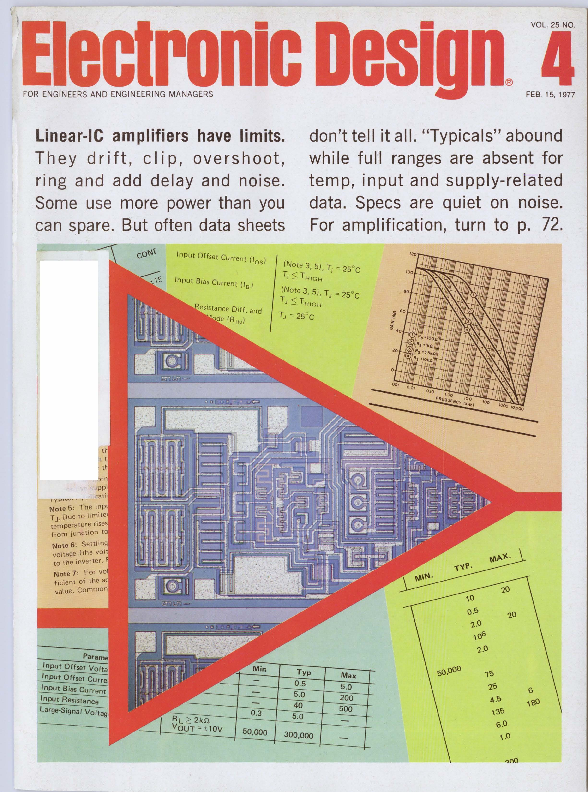
Linear-IC amplifiers have limits. They drift, clip, overshoot, ring and add delay and noise. Some use more power than you can spare. But often data sheets
don't tell it all. "Typicals" abound while full ranges are absent for temp, input and supply-related data. Specs are quiet on noise. For amplification, turn to p. 72.
Input Offset Current Uos!
Input Bias Current ( I )
9
(Note 3, 5), Ti =25 oC
Ti $ T HIGH
(Note 3 , 5), TJ = 25 oC
T J $ T H/GH
TJ = 25 � C
I y ....,,..,._. , ' . ,....-,
Note 5 : T he inp� T J� Due to limite1 temperature nses from junction to Note 6: Settling voltage (the volt to the inverter . f
Note7 : Forvol ficient of the ac value . Common
Parame Input Offset Voit; Input Offset Curre1 Input Bias Current Input ResistanceLarge-Signal Volt:;Q",
0.3 50,000
Typ
0.5 5.0 40 5.0
300,000
Max 5.0 200 500
o.S
io
i .o
\06
i.o
1s
is
6
A.S
,so
\'3S
6.0
\.0
... here today at no extra cost in every Trimpot� Potentiometer
Swage-Bond'" eliminates pin termination failure, provides , more reliable tempco. Microphotograph shows trimmer element magnified 20X .
I
HERE'S PROOF:
-
- .--4--~
I
t
.
.
Amplitude Modulation
Model ZFSC 2-4
KHz-1000 MHz ower Splitter/Combiner
$4e """""'""""''~'~ a single unit...
Mod1I No. IPrlco�Qlv.I
IFSC 2-1 IFSC 2�1W IFSC 2�2 IFSC 2-4 1131.95 4-241 1135.95 4-241 1139.95 "241 1144.95 "241
Frequency Range tMHz l
lsol11lonldBI Lowei band edge to one decade h1gh11 Mid 1ange Uppe1 t>and edge 10 one octave lower
Insertion Lon /dB i above 3 dB spht Lower band edge to
one decade h1gh11
Mid range Uppe1 band edge lo one octave lowei
5 �~ 1 -7 50
10-1000
1-
Typ Mm Typ Mm lyp Mm
30 25 28 2()
30 25 28 2()
30 2() 25 2()
25 2()
25 2()
-i
Typ MaJC Typ MaJC
23 18 Typ MaJC
02.JOOO Typ Mm 2() 12 25 2()
23 18 Typ MaJC
02 05 03 06
06 08
02 05 04 08
08 10
0 2 05 05 10
09 12
02 05 05 10
09 12
Phan Unb1l1nce (dBi Lowe1 band edge to one oc1aveflomupp11 band
Typ MaJC 05
Typ MaJC 05
Typ MaJC 05
Uppe1 band edge to one
oc1ave from lower band 1
1
1-
t-
AmpHtude Unb1l1nce tdB) Typ Max Typ Max
Lower band edge to one
octave from uppe1 band 0 05 0 15 005 0 15
Typ MaJC 005 0 15
Uppei band edge to one oclave_ -'"_m_l_ow_e_� b_a_nd~ 0 1___! 3 L 0 1 ~ 0 I 0 3
Typ MaJC 05
Jyp MaJC 005 0 15 0 I 03
Common 1peclllc1llons: lmpe<laoce all ports - 50 ohms VSWR - I 25 typ Nominal phase d1tle1ence - 0 Matched powei 1atmg - 1 wall maJC Internal load d1Ss1pa11on - '� wall I'� wa11 ZFSC 2�1Wl
Yes ��� It's no longer necessary to order several different models of power splitters/combiners if your designs are within the 200 KHz to 1000 MHz region. If your design is relatively narrow band, you can expect tighter specs.
Order Mini Circuits new, versatile model ZfSC-2-4 offering these benefits:
� ultra wideband performance, 200 KHz to 1000 MHz � tighter specs over narrower band range � lower cost with single-model, high volume purchasing � fast delivery, one week maximum
for narrower bandwidth applications models in the ZfSC series are available at low prices starting from $31.95 (see chart}
World's 1arges1 manufacturer of Double-Balanced Mixers
l;J !c~r~sil7b~o~yrCU its
A 01v1s1on Sc1enlfl1c Components Corp
837.143 Utlc1 Affnue: Brooklyn, NY 11203
(212) 342-2500 lnl'I -.-1.. 620156 Domeodc -.-1ex 125490
lnternetlonal R� preaenmflvea: 0 AUSTRALIA; G"'n"1dl f:.l1..:c1111rur. ~~rv11 , ..., 4'' Al1 �,l(~u 011..r Stfl'�~t Nl'w'-iouth Waif !:-; Au">lra11a ?fl65 0 ENGLAND: Dale Elcclronics_ Dale House Wnarf Road Fnmley
~~~~~e~~~~QQ~err~~~1~~1 ~a~~~~~~n~ co 1 1iRfe~; ~n~11~rrn~~ ~~~� ~~,~~;:;,11~:1~11'.'1'.~.~ 1 !'1c�~ ~a~~s:~~'~t't'81~c~P~::~~~s~~~~:':I~dAE:u~~~~~~~NJ>; 1~~uhs~~~ ~~~~~~~u~~08~,,,K~~~~~-
Tokyo O EASTERN CANADA; B D Hummel. 2224 Maynar<l Avr�nu� Ul1<�n NY 1t~1lli' 131'11 rm IH:> I 0 NETHERLANDS, BELGIUM, LUXEMBOURG: Co1meic: Veldweg 11 Hallem. Holtanct
o NORWAY; Oatama11k AS. Ostens1011e1en 62 Oslo 6. No1wav
U.S. Dl�trlbutora: 0 NORTHERN CALIFORNIA; Ga1ri-Wru1r. & Co f 001h1\I Ollio: C-1�1111�1 10'1 f Hm1on1 A11t�1H1(� Los Altos CA 94022 (4151 9"49.5533 0 SOUTHERN CALIFORNIA, ARIZ ONA;
Cr Q Ele 1
40 Colin Ir
a HQ!!ywood A l
2 13 l .: ~'>f
For complete information and specifications see Microwaves' "Product Data Directory '', Electronic Designs' "Gold Book" or Electronic Products' "EEM".
CIRCLE NUMBER 3
2
ELECTRONIC DESIGN 4, February 15, 1977
NEWS
21 News Scope
26 Wage busting is continuing to plague engineers. but legislative help may be on the way.
34 First monolithic 12-bit DAC design details are revealed.
57 Washington Report
TECHNOLOGY
43 Microprocessor Design
72 FOCUS on linear IC amplifiers: Mixed bipolar/FET processes and other advances have pushed monolithic amplifiers to new performance heights. But you'll have to push hard to get all the required performance specifications.
86 Driving inductive loads? Take advantage of collector-emitter diodes in monolithic power Darlingtons. They can be as effective as external diodes.
94 Use equatio.ns to parallel transistors. To get through the graphical morass, balance your currents with simple arithmetic and straight-line approximations.
100 Float your input amplifier and you can al�most laugh at ground loops or high common mode-voltages. A new design gives low drift, too.
106 Measure phase .noise in one of three ways, each of which has some advantages. Quadrature phase detection, for one, lets you avoid dynamic-range limits.
112 Measure SAW-device characteristics, and pin down the performance of acousticwave filters and delay lines. Frequency response and impedance are key specs.
120 Build a high-frequency sy�nthesizer with a digital mixer in a phase-locked loop and use fewer and slower divider/counters in conventional loops.
126 Dick Lee of Siliconix speaks on making your engineers bigger.
132 Ideas for Design: Convert seven-segment .numerical code to decimal with simple gates. Optical couplers isolate, control and monitor to allow 6-kV supply to float. Approximate the tangent function with a multifunction converter and op amp. Trace symbols on CRT screen with access to the Z axis.
140 International Technology
PRODUCTS
157 Instrumentation: Low-cost scope challenges more expensive rivals.
143 Integrated Circuits
173 Discrete Semiconductors
163 Packaging & Materials
175 Power Sources
165 Data Processing
179 Modules & Subassemblies
169 Components
DEPARTMENTS
65 Editorial: The good word
7 Across the Desk
191 Vendo~ Report
181 Application Notes
196 Advertisers' Index
183 Evaluation Samples
198 Product Index
184 New Literature
198 Information Retrieval Card
190 Bulletin Board
Cover: Designed by Art Director Bill Kelly, photo courtesy of National Semiconductor, Santa Clara, CA.
ELECTRONIC DESIGN is published biweekly by Hayden Publishing Company, Inc., 50 Essex St. Rochelle Park, NJ 07662. James S. Mulholland Jr., President. Printed at Brown Printing Co., Waseca, MN. Controlled circulation
postage paid at Waseca, MN and New York, NY, postage pending Rochelle Park, NJ. Copyright � 1977. Hayden
Publishing Company, Inc. All rights reserved. POSTMASTER: Please send form 3579 to ELECTRONIC DESIGN, P.O. Box 13803, Philadelphia, PA 19101.
ELECTRONIC DESIGN 4, February 15, 1977
3
II
-
II
�
4
ELECTRONIC DESIGN 4, February 15, 1977
If you 're a MOS microprocessor customer, the last few years haven 't been a whole lot of laughs .
One supplier had all the good stuff , made all the rules , told you what you could buy. And when . And fo r how much .
But something happened to change all that: Advanced Mic ro Devices.
We make the best microprocessor in the world , the Am9080A , and we make all the support circuits you need They're yours now, off the shelf , at competitive prices . That's right . Competitive .
But we make more than m icro processor products We ma ke you a promise :
We 'll sell you any part, in any quantity, bundled or unbundled You 're the customer.
So , if you suddenly find yourself having an easier time buying microprocessors , just remember why. And who .
If you 're shy, and you 're just not sure how to say thank you , an order would be really nice .
Write or phone Advanced Micro Devices , The Buyer's Market.
Ours and Theirs. (The 9080A & 8080 A)
Specification
Intel
AMO
Minimum Instruction Cycle Time
Maximum Power Dissipation (at 1.3 microsec . 0-70� )
Output Drive
Minimum Input H ig h Voltage
MIL-STD-883
1.3 microseconds
1307 milliwatts 1.9mA @ .45V
3 .3V Special
1 microsecond
829 milliwatts 3 .2mA @ AV
3 .0V Standard
Ours and Ours.
(Am9080A System Circuits)
AMO Part Number Description
Availability
AMO Part Number Description
Availability
CPU
SECOND SOURCE SUPPORT
Am9080A/- 2/- 1/- 4 Oto + 70� C
Am9080A/-2/- 1
- 25 to + 85� C
Am9080A/- 2
- 55 to + 125� C
Stock Stock Stock
STATIC READ/ WRITE RANDOM ACCESS MEMORIES
Am9101 A/ B/ C/ D Am91 L01 A/ B / C Am9102A/ B/ C/ D Am91 L02A/ B/ C Am9111 A/ B/C/ D Am91L11 A/ B/C Am9112A/ B / C/ D Am91L12A/ B/C Am9131 A/ B/C/ D/ E Am91 L31 A/ B/ C/ D Am9141 A/ B / C/ D/ E Am91L41A/ B/ C/ D
256 x 4 . 22 Pin 256 x 4 . 22 Pin 1K x 1. 16 Pin 1Kx 1. 16 Pin 256 x 4. 18 Pin 256 x 4. 18 Pin 256 x 4. 16 Pin 256 x 4. 16 Pin 1K x4 . 22 Pin 1Kx4 . 22 Pin 4K x 1. 22 Pin 4Kx 1. 22 Pin
Stock Stock Stock Stock Stock Stock Stock Stock Stoc k Stock Stock Stock
DYNAMIC READ/ WRITE RANDOM ACCESS MEMORIES
Am9050C/D/E Am9060C/ D/ E
4K x 1. 18 Pin 4K x 1. 22 Pin
Stock Stock
MASK PROGRAMMABLE READ-ONLY MEMORIES
Am9208B/ C/ D Am9216B/ C Am8316A Am8316E
1K x 8 . 250 nsec max 2K x 8 . 300 nsec max 2K x 8 . 850 nsec max 2K x 8 . 550 nsec max
Stock Stock St ock St ock
ERASABLE READ-ONLY MEMORIES
Am1702A Am2708
256 x 8 . 1O 1.sec 1K x 8 . 450 nsec
Stock 1st O 1977
CPU: 9080A = 480 nsec - 2 = 380 nsec - 1 = 320 nsec - 4 = 250 nsec MEM : A = 500 nsec B = 400 nsec C = 300 nsec 0 = 250 nsec E = 200 nsec
Am8212 Am8216 Am8224 Am8226 Am8228 Am8238 Am8251 Am8255 Am8257 Am8259
Am8238-4 Am9511 Am9517 Am9519 Am9551 /- 4 Am9555/ - 4 Am25LS138 Am25LS139 �Am25LS273 �Am25LS373 �Am25LS374 �Am25LS377 �Am25LS2513 �Am25LS2537 �Am25LS2538 �Am25LS2539
8-b1t 1/ 0 Port Non-Invert ing Bus Transceiver Clock Generator Inverting Bus Tran sce iver System Controller Extended Write System Controller Prag Communications Inter face Prag Peripheral Interface Direct Memory Access Controller Priori ty In terrupt Controller
Stock Stock Stock Stock Stock Stock Stock Stock 2nd 0 1977 2nd 0 . 1977
IMPROVED SUPPORT
REPLACES
High Speed System Controller N/A
Stock
Arithmetic Processing Unit
N/A
2nd O 1977
Multi-mode OMA Controller 8257
2nd 0 . 1977
Universal Interrupt Controller 8259
2nd 0 1977
Prag Communications Interface 825 1
Stock
Prag Peripheral Interfac e
8255
Stock
1-of-8 Decoder
8205
Stock
Dual 1-o f-4 Decoder
8205
Stock
8-b1t Common Clear Register N / A
Stock
8-b1t Tran sparent Latch
8212
2nd 0 1977
8-b1t 3-State Register
8212
1st 0 1977
8-b1t Common Enable Register 8212
1st O 1977
Pri ority Encoder
8214&8212 Stock
1-o f-10 3-State Decoder
8205 (2)
1st O 1977
1-o f-8 3-State Decoder
N/ A
1st O 1977
Dual 1-o f-4 3-State Decoder N/ A
1st 0 1977
'All combine high performance and low power 1n space saving 20-pin package
Advanced Micro Devices
Bipolar LSI. N-channel , silicon gate MOS. Low-power Schottky.
Multiple technologies. One product: excellence.
Advanced Micro Devices� 901 Thompson Place, Sunnyvale, California 94086 �Telephone (408) 732-2400 � Distributed nationally by Hamilton/ Avnet, Cramer and Schweber Electronics.
CIRCLE NUMBER 6
ELECTRONIC DESIGN 4, February 15, 1977
5
CIRCLE NUMBER 4
6
Sr. Vice President, Publisher
Peter Coley
Editors
Editorial Offices 50 Essex St. Rochelle Park, NJ 07662 (201) 843-0550 TWX: 710-990-5071 Cable: Haydenpubs Rochellepark
Editor-in-Chief George Rostky
Managing Editors: Ralph Dobriner Michael Elphick
Senior Associate Editor Stanley Runyon
Associate Editors: Sid Adlerstein Dave Bursky Morris Grossman John F. Mason Max Schindler
Contributing Editors: Peter N. Budzilovich, John Kessler Alberto Socolovsky, Nathan Sussman
Editorial Field Offices
East Jim McDermott, Eastern Editor P.O. Box 272 Easthampton, MA 01027 (413) 527 -3632
West Dick Hackmeister, Western Editor 8939 S. Sepulveda Blvd., Suite 510 Los Angeles, CA 90045 (213) 641-6544 TWX: 1-910-328-7240 Dave Barnes 844 Duncardine Way Sunnyvale, CA 94087 (408) 736-6667
Editorial Production
Marjorie A. Duffy, Production Editor James Keane, Copy Editor
Art
Art Director, William Kelly Richard Luce, Anthony J. Fischetto
Production
Manager, Dollie S. Viebig Helen De Polo, Anne Molfetas
Circulation
Director, Barbara Freundlich Trish Edelmann
Information Retrieval
Paula Greenleaf
Advertising Promotion
Susan G. Apolant
ELECTRON IC D ESIGN 4, February 15, 1977
Marcoflex. The switch that turns people on.
Another HP-25 variation
I have received many letters from other ELECTRONIC DESIGN readers in response to my letter, and I have exchanged calculator programs with many of them. I was interested in Mr. Lewart's letter (ED No. 15, July 19, 1976, p. 11 ) in which the HP-25 program given for the binomial coefficient evidently has several misprints.
A program can be written in 17 steps with the same general procedure apparently used by Mr. Lewart, but with one less storage register. (This may be important because in general program use, the HP-25 has a couple of storage registers less than could be effectively used by the sizes of programs possible. ) Here is a variation of that program, which is suitable for stand-alone use, but which is even shorter.
I+ i
RCL4 R CL 7 gx=O GTO 14
x
1 STO- 4 ST0-7
CLx GT003
J, J,
n To compute k n k, fPGRAM, fREG, R/ S. It is preferable to use the smaller of k and (n-k ) for k. (The other program version is obtained by r eplacing the first two steps with STO 7; ~ ;STO 4 ; 1 ; and increasing the addresses in the GTO statements by 2. Then the fREG is not needed. )
The programmable pocket calculator quickly seems to be r eaching a
calculation capability that makes it competitive with computer use in many situations. The readers of ELECTRONIC DESIGN seem determined to stay in the forefront of such developments.
H enry E . Schaffer Professor of Gen etics North Carolina State University School of Agriculture and Life Sciences Box 5487 Raleigh, NC 27607 Ed. Not e: A corrected version of Mr. L ewart's program a'PPeared in the October 25 i ssue.
Get your Optical Industry Directory
The 1977 two-volume edition of The Optical Industry & Systems Directory is now available. Vol. 1 is a buyer's guide listing over 1200 categories of products and services. Vol. 2 is an encyclopedia-dictionary of optical, electro-optical and laser technology. Both volumes are available for $32 (prepaid USA ) from The Optical Industry & Systems Directory, Dept. B77, P.O. Box 1146, 59 Bartlett Ave., Pittsfield, MA 01201. Vol. 2 only sells for $12.95 (prepaid USA ) . Vol. 1 is not sold separately. Add $3 for the set and $2 for Vol. 2 for postage and handling.
Real world can be a rough place
Leland Langston's circuit for detecting asynchronous data edges (ED No. 22, Oct. 25, 1976, p . 192 ) is beautifully simple. In the real world, however , things often aren't so simple.
If the data input is truly syn( continued on page 8)
Electronic Design welcomes the opinions of its readers on the issues raised in the magazine's editorial columns. Address letters to Managing Editor, Electronic Design, 50 Essex St. Rochelle Park, N.J. 07662. Try to keep letters under 200 words. Letters must be signed. Names will be withheld on request.
ELECTRONIC DESIGN 4, February 15, 1977
". . . amazingly simple and reliable'.' "Why didn't I think of it?"
People are really getting turned on by our new Marcoflex 650 switches.
Which doesn't surprise us. After all, its patented flexing spring action is something of a breakthrough.
An incredibly simple design gives you electrical and mechanical characteristics associated with 1 larger switches in a miniature, .625- � inch package at an economical price.
Features include wiping action, multiple-point (bifurcated) contact, true snap action, high contact force, and positive tactile feel.
Plus alternate or momentary action, and excellent reliability.
Get turned on by Marcoflex yourself. Contact us today for full details.
The patented Marcoflex mechanism.
ILLUMINATED PRODUCTS INC.
A subsidiary of OAK Industries Inc. 2620South Susan St., P.O. Box 11930
Santa Ana, CA 92711
ooiiJ 0 Telephone: 714/540-9471TWX910-595-1504 ~ COMPONENTS GROUP CIRCLE NUMBER 5
ACROSS THE DESK
(continued from page 7) chronous, its transition may violate the set-up/hold requirements of flip-flop FF1� Behavior of the flop under such conditions is not specified. FF1 may be unable to resolve the input; it may glitch-enter an unstable state that, in the case of TTL, may last much longer than the specified propagation time of the circuit. The resultant output of gate G1 may very well look like this:
DATA IN
CLOCK A B
c
~
~
DD
Lill
DD I I nn
x
y
Either or both glitches, X and Y, may be present, giving a variable total of from two to four output pulses.
Therefore, the data input to FF1 must be synchronized with the clock in order for the given circuit to function reliably as intended.
Richard F. Binder Engineer
Modular Computer Systems, Inc. 1650 W. McNab Rd. Fort Lauderdale, FL 33309
A �petite' protest
In "Compact High Voltage Supply StandS' TaH in Performance" (ED No. 17, Aug. 2, 1976, p. 100), you make an apples and oranges comparison of three high-voltage power supplies. No mention is made that two of the three are designed to meet MIL specs, operate over a tempe1�ature range of -55
to + 71 C, and be able to survive
the MIL environments. The featured supply is commercial grade.
The article also implies that you get more for your dollar if you buy a large rather than a "petite" HV power supply. We can state from our experience that to squeeze 12 AVDC into a 6.4 in.3 case, provide comparable stability and regulation as power supplies three times the volume and meet all the MIL vequirements at the same time are
8
far more difficult and expensive. LectroLogie not only did this but we built our LP power supply with only hermetically sealed semiconductors, and used established reliability components.
Irwin B. Galter President
LectroLogic Inc. 9406 N. 107th St. Milwaukee, WI 53224
Misplaced Caption Dept.
and making them work uncompensated overtime. And when the interests of these men conflict with those of the working EE-as they often do--history shows who gets served first.
No other trade or professional association, union or federation would allow a member of management to be a union or association member, let alone a leader or officer! It is time we stood up to demand of the IEEE a stop to conflict-of-interest leadership. Then, and only then, will the IEEE become an organization that truly represents the engineer.
Robert Clare Well Corp. 54 Cottage St. Taunton, MA
Welcome to Thomson CSF. Our chief engineer will be right with you.
Sorry. That's the Boucher Room in the Frick Collection, New York City.
Of layoffs and leadership
Layoffs , layoffs, and more layoffs-is that what today's young engineer has to look forward ito? A�s a young engineer new to the ranks of electrical engineering, I have already witnessed the deleterious effect.s upon both my colleagues and classmates: Graduates can't get jobs, and engineersoften the older, over-40 crowd-are laid off much too frequently, often having to support a wife and family on unemployment.
Yet I constantly read in our newspapers that engineers are in such great demand. Who is originating these stories? Could the IEEE be behind this dastardly deed?
Now I hear the IEEE leadership is dominated by academics and company executives, men who earn their livelihood by graduating more engineers, paying them less,
Leadership
A corollary to your editorial, "COMPANY POLICY," in the December 6th issue, could relate to the willingness of managers to be led by the computer. "It is a 'sophisticated' tool; we are sophisticated; ergo we will work with it. It is faster (hence better) than we are; so we will follow it."
Martyn Hodes Spectral Dynamics Corp.
of San Diego San Diego, CA 92112
FCC �interference' beats equipment interference
The article on EMI/RFI (ED No. 20, Sept. 27, 1976, p. 24) is definitely not up to your usual standards. Even on the cover of the magazine, you point out that EMI / RFI is "racing out of control," but then you go on to complain about the actions of the FCC to reduce these problems.
I, for one, applaud the FCC for finally getting in gear to update its regulations, and I think your magazine and our profession should offer help and solutions that provide jobs rather than allow selfish interests to whine about "interference." Better a little government interference than a lot of rf interference!
Wilson Lamb Research Associate Ocean Engineering Department University of Rhode Island College of Engineering Kingston, RI 02881
ELECTRONIC DESIGN 4, February 15, 1977
-h ~ MEASUREMENT
COMPUTATION
product advances from Hewlett�Packard
FEBRUARY 1977
Direct connection is made to the microprocessor with the "clothespin" clip. The EXTERNAL connections are through separate leads. These may plug directly onto test pins, or they may be inserted in pincher-type miniature probes as shown. The display on the CRT is a probe test verifying internal operations of the logic analyzer.
MEASU REM EN'fECOMP UTA TION' NEWS
A new logic analyzer dedicated to debug microprocessor-based systems
As new applications for microprocessor-based systems proIiferate, Hewlett-Packard recognized the need for an instrument that could hand le the vast quantity and complexity of data during system debugging. This measurement need resulted in the development of the new HP 1611 A logic state analyzer with powerful triggering capabilities, mnemonic display and time interval measurements, saving you a significant amount of time in debugging microprocessor-based systems.
An extremely important feature of
(continued on third page)
of Hertz and Gigahertz ..... part 1 in a series
Economical counters
- �-
-� 0 11.
-�- MUSii- n"u"
......,., ,..,._
~U@U:~
The 80 MHz 5381Aand1 .3 GHz 53008/53058 are two of the choices HP gives you in economical counters. Two of the eleven 53008 modules are at the right ; the D/A converter and battery pack.
Many counter problems only require a simple, economical and dependable instrument. It is for this reason that the frequency-only 5380 family and the modular 5300 system were developed .
The 5381A,5382A, and 5383A represent an inexpensive solution to a frequency only measurement problem up to the frequency ranges of 80 MHz, 225 MHz, and 520 MHz, respectively. Al I these counters feature direct count-
ing capability (a resolution of 1 Hz in 1 second), as well as an optional TCXO for improved measurement accuracy.
For applications involving counter measurements other than just frequency, the modular 5300 system is an excellent and economical so lution . Configurations can be changed to meet different needs by simply snapping on an appropriate module. For example, frequency extensions to 1.3 GHz, time interval measurements to
1 ns, battery operation, digital multimeter, and even "talk" capability on the H-P Interface Bus are just some of the possibilities with the expandable and economical 5300 system.
For the whole story, check Kon the HP Reply Card.
HP-18 programmable word generator with pulse parameter control for thorough digital testing
Hewlett-Packard's 8016A word generator is a versatile 50 MHz data source ideal for digital testing applications. Using it, you first set up your test pattern in the generator's 9-channel by 32-bit memory. By adjusting clock and inter-channel delays, pulse widths and amplitudes, you can easily simulate worst case or other conditions.
Multi-channel parametric tests such as set-up times , hold times, propagation delay, critical timing, sensitivity and noise immunity tests, are now easy with the total capability of the 8016A.
Now, you can use the 8016's multi-channel capabilities in CMOS applications as well. A new accessory, the HP 15451 A TTL to CMOS translator, amplifies 4 channels of TTL information to CMOS levels with pulse amplitudes determined by the CMOS power supply.
In combination with HP's 1600A logic analyzer, you have a practical stimulus-response combination for observing your logic circuits in action. Functional tests of your logic circuits, memories , microprocessors , etc. can be performed quickly with the 8016N1600A combination.
A remote programming capability, (Option 001) allows fast loading of data to the instrument's memory with an HP Interface Bus compatible card reader, calculator, or� minicomputer-a valuable option for on-I ine testing where speed and accuracy are important.
For details on this powerful word generator, check Mon the HP Reply Card.
MEASUREMEN"fECOMPUTA TJON' NEWS
Microwave synthesizer application note now available
Conversationally interactive programmable data logger also operates in unattended mode
A new HP Application Note 218-1, Applications and Performance of the HP 8671A/8672A, details applications ranging from satel Iite communications testing to electronic warfare and component test. The 8672A (MIC News, May 1976) has AM/FM modulation and calibrated output usually associated only with signal generators but also resolution, spectral purity, stability and programmability of a high quality synthesizer.
A typical section of the note describes a technique to obtain finer frequency resolution of 1, 2, or 3 Hz at microwave frequencies from .2 to 18 GHz. Another section covers considerations and additional equipment required for microwave coverage to 36 GHz by use of external doublers.
Other sections provide detailed information on the actual operational
c
- -- �..
-: ~ . ..
01
For precision signal simulation from 2 to 18 GHz, the HP 8672A provides + 3 to -120 dBm signals with AM and FM modulation, and all front panel functions remotely programmable.
performance of the 8672A, giving the user considerable help in getting the synthesizer applied to his job quickly. For example, specific synthesizer programming sub routines are listeq and annotated to assist in writing application programs.
For your free copy, check Ron the HP Reply Card.
Dedicated logic analyzer (continued from first pageJ
the 161 lA is its ability to display the mnemonic set used by the microprocessor in the system. If cycle-bycycle analysis is desired, the data can be displayed in the absolute mode where the display is in hex or octal machine language. Eight additional uncommitted probes allow you to relate activity elsewhere in the system.
With new highly sophisticated triggering capabi Iities, the 1611 A perm its the framing of a real-time data window around virtually any event, or set of related events or desired sequence of
system operations. The 1611 A also accurately measures execution time or counts selected events between two keyboard-selected events.
Mnemonic display has been made possible by the use of "personality" modules-consisting of special circuits and microprocessor probe-to monitor specific microprocessors. Presently, two options are available: Option 080 for the 8080 and Option 068 for the 6800. Additional optional modules will be available shortly. To reconfigure your analyzer, parts can be ordered as a kit and easily exchanged in about 15 minutes.
An internal 8-bit MOS microprocessor is used as a controller in this new keyboard controlled logic state analyzer. The CRT displays both the measurement conditions and results.
A programmable data logger is a system to collect and analyze data, make decisions based on the data and interact with the test, process, experiment, instrument, or the system which generates the data.
The 3051 A system can measure de from 1microvoltto200Vwith1 �.volt resolution, ac from 10 �.volts to 200 V with 10 �.volt resolution, and ohms from 1milliohmto10Megohmswith 1 milliohm resolution. The system measures de at five channels per second, ohms and ac at 4 channels per second.
System configuration includes the HP 3455A high accuracy/resolution 61/i-digit DVM, a 3495A input multiplexer, a 9815A computing controller, and a 9815A HP-IB 1/0 card.
The user communicates with the system via an alphanumeric keyboard; the system communicates with the user by a numeric display and an alphanumeric thermal strip printer. This conversational interaction capability allows the system to be operated by personnel with no formal knowledge of programming or data logging. Auto start capability allows the system to operate unattended.
For more information, check 0 on the HP Reply Card.
M�ASUR�M�NIECOMPUTATION,NEWS
For detailed information , c heck B on the HP Reply Card.
The Hewlett-Packard 3051 A data logging system scans from 1 to 80 channels of analog data. A ten channel relay actuator card provides alarm and multiple switching functions.
Easy tape duplication with expandable storage up to 1 Mbyte using new external memory unit
Now, interface your 9825A desktop to a teletype or a remote computer
The HP 9877A External Tape Memory is a self-contained peripheral that can hold up to four cartridge drives to expand the capabilities of the HP 9825A desktop programmable calculator. Using the same cartridge unit, storage capacity from 250,000 to 1 Million bytes is now provided in increments of 250,000 bytes.
Each tape cartridge unit.has a builtin two-track drive which provides rapid access to data and programs with automatic verification of all stored information. A 2,750 byte/second data transfer rate and a 228.6 cm/second search speed makes it a very fast and inexpensive method of storing, retrieving or duplicating data. An HP 9877A, fitted with four tape units, takes about six seconds to locate any file from any tape in the unit.
Using the duplicator program supplied with the 9877A, a full master cartridge can be copied and verified in about 16 minutes. Two copies, from the same master data tape, are sequentially copied and verified in 26 minutes and four copies in 50 minutes.
For more information on expanding tape storage capability, check Pon the HP Reply Card.
External tape memory presents an inexpensive method of storing large volumes of data plus the convenience of duplicating cartridge tapes.
Data can now be gathered from a remote terminal or computer, reduced and analyzed by the high speed processing of the 9825A desktop, and results returned to the remote location.
The HP 98036A bit serial interface opens new areas of application for the HP 9825A desktop computer. In addition to bit parallel, binary coded decimal, and HP-IB (Hewlett-Packard ' s implementation of IEEE Standard 488-1975) interface capability, the advent of the 98036A allows connection to such devices as teletypes, CRT terminals, and telephone modems.
Because of the flexibility of the 9825A desktop computer, the 98036A can be used to configure the 9825A as a timeshare terminal. This allows the keybbard of the 9825A to be used to send information to a remote computer. The 9825A display or an attached printer can be used for output information received from the remote computer eliminating the need for another terminal in a distributed system.
The vectored interrupt ca pa bi Iity of the 9825A further enhances the usefulness of the 98036A. The desktop computer' s buffered input/output scheme will allow multiple interfaces to communicate simultaneously with different remote devices while locally executing another program . Priority interrupts ensure that more important information can be dealt with quickly to maximize system throughput.
Configuration of the 98036A is ac-
complished via internal switches and by programming the 9825A. The number of bits per character, parity, internal/external data clocking, and bit rate are configured by the user. The 98036A operates in an asynchronous mode with data rates from 75 bits per second to 9600 bits per second.
For complete information, check E on the HP Reply Card.
Three more spectrum analyzer application notes
Three new application notes relating to spectrum analyzers have just been published. Subjects of these brief, informative notes are:
AN 150-9: Noise Figure Measurement AN 150-1 O: Field Strength Measurement AN 150-11: Distortion Measurement
In each case, the theory is reviewed, measurement procedures described, and examples of measurements presented . Advantages and tradeoffs that apply to using the spectrum analyzer are discussed . For free copies of these new notes, just
check Q on the HP Reply Card.
MEASUREMEN"fECOMPUTATION' NEWS
New display station handles both APL and ASCII data
Use the power of APL on a small general purpose computer
Hewlett-Packard designed the 2641 A Display Station to complement the power and elegance of the APL language. Key to the secret of APL's capabi Iity is ad isti nctive set of characters, each one symbolizing a powerful operation.
The 2641 A is a member of the 2640 family of HP terminals that pioneered internal mini-cartridge mass storage and offers features such as self-test and "soft keys". The 2641 A has these family features, plus a versatile keyboard labeled with both the APL and standard ASCII characters.
The 2641 A supports a full 128 APL character set, a 64 character overstrike set and a 64 character Roman set. These sets represent the special symbols used on IBM and Burroughs systems, and most symbols used by timeshare bureaus that support APL.
Overstruck characters, an APL innovation, are a combination of two existing characters and are produced by striking one key, backspacing, and striking a second key. Without the high resolution display of the 2640 family, overstrike characters would be difficultto read . The 2641 A assures crisp, clear characters.
After a user inputs an overstrike character, a search and compare with the existing set in memory assures that the character is valid .
The full complement of display enhancements (inverse video, blinking, half-bright, etc.) are standard, and the optional line drawing set allows the creation of readable forms with visual prompts .
For more information on the 2641 A, or other famil y members, check C on the HP Reply Card.
With the advent of APL\3000 in conjunction with the HP 3000 Series II computer and a new interactive terminal , the 2641 A, designed especially for the language, APL is now more readily available as a new dimension in computational capabi Iity.
APL\3000 is the first APL software available on a low-cost general purpose computer. Patterned after APLSV, this enriched version from HewlettPackard is particularly useful for business, education, scientific and engineering applications involving the manipulation of large data arrays.
APL, A Programming Language, has a large following of users, who embrace its use for its capacity to express complex mathematical applications in a concise manner; numerous computer operations can be compressed into just a few lines of code.
Because of its mathematical power, APL is of growing interest to those in the fields of statistics, finance . forecasting and modeling.
Hewlett-Packard' s APL\3000 has the following enhancements: Large workspaces. Since work spaces are virtual, they are effectively limited onl y by the on-line disk storage available. As code is needed and used , it is brought from disk into main memory. APL\3000 is infinitely more useable with this close-to-infinite workspace. Microcoding the "virtual workspace" scheme results in faster execution. Dynamic compiler. APL is implemented as a dynamic, incremental compiler and not a simple interpreter; compiled code is preserved and when possible, used repeatably without recompiling. The result is faster execution of repetitive programs.
MEASUREMEN'fECOMPUTATION, NEWS
Powerful easy-to-use editor. The APL\3000 editor is a full text editor as well as a function editor. Commands are given in English-like words. Anyone who has made a mistake in editing will appreciate "UNDO" which allows quick recovery from an editing error avoiding long, complex recovery edits typical of most editors today. Use of microcode. The most ti me consuming aspects of the subsystem have been microcoded to speed operation.
The 3000 Series II computer treats APL\ 3000 as a standard language subsystem. When APL is executing, up to 16 terminals may be operating either in batch or interactive mode, with any of the 3000's other languages: fORTRAN, COBOL, RPG, BASIC and SPL.
For additional details , check A on the HP Reply Card.
A new interactive terminal designed especially for APL, provides a clear, sharp display. APL is a terse and concise language for describing processes and algorithms.
Multiprogrammer expands Step attenuators now your testing capabilities operate de to 26.5 GHz
Take your instrumentation tape recorder with you
Test engineers can now plug offthe-shelf units together and assemble their own automatic test and measurement system quickly and economically. A calculator-based HP Interface Bus (HP-IB) multiprogrammer system is designed for ease in communicating bi-directionally with your device under test.
A basic system includes the controller, (a desktop programmable calculator HP 9825 or 9830) connected via the HP-IB to a multiprogrammer interface unit, a 6940B multiprogrammer, and from 1 to 15 randomlyaddressable 1/0 cards that plug into the 6940B mainframe.
Up to 15 extender mainframes, each holding 15 plug-in cards, can be combined permitting system expansion up to 240 1/0 channels controlled by a single calculator.
Input card functions include current or voltage monitoring, digital input, counting, and event sensing. Output functions cover stimulus and control including voltage, current, resistance, relay contacts, digital bit patterns, stepping motor control , time and frequency references.
For more details, check Lon the HP Reply Card.
The APC-3.5 connectors used on these HP 84950/ K 70 dB step attenuators are fully compatible with the industry-standard SMA.
Considerable microwave activity is now focusing on coaxial designs above 18 GHz. Such diverse areas as satellite communications and electronic warfare require measurement components operating to 26.5 GHz and beyond.
The new HP-developed APC-3.5 coaxial connector provides a modefree, beaded, air line for operation to 34 GHz (Microwave Journal, July '76). By use of this new connector, a step attenuator from the HP 8495 series is able to operate de to 26.5 GHz.
HP 84950 manual step attenuator offers 70 dB range in 10 dB steps. HP 8495K is the programmable version with the same specifications. Solenoids operate from 20-30 volts at 110 mA. These attenuators are composed of four attenuator sections (one 10 dB card, and three 20 dB cards) connected in cascade. Each section consists of a precision thin-film attenuator card, a lossless thru line, and a ganged pair of gold plated center conductor contacts that switch the attenuation card in and out. This combination results in high accuracy and excellent repeatability (typically 0.03 dB).
Now HP instrumentation tape recording quality is available to you in the field, where and when you need it. A de to ac inverter, capable of operating your HP 3964A or 3968A instrumentation tape recorder, from either a 12 or 28 de voltage source is now available as Option 021.
This new inverter option is included as part of the recorder itself and is specified as part of the original purchase. Total weight of the recorder with inverter is 31.3 kg (69 lbs).
If you have need for a rugged, portable tape recorder to be used in a variety of applications, send for data on the HP 3964A and 3968A recorders. Please check Fon the HP Reply Card.
A 66-page catalog describing consumables available for HP plotters, x-y recorders, strip chart recorders, oscillographic recorders, and instrumentation tape recorders is available.
Check G on the HP Reply Card.
HP-IB multiprogrammer building-block components bring the power, economy , and ease of programming of HP desktop programmable calculators to your automated testing system.
For details, check Non the HP Reply Card.
Analysis of vibration is possible when you transport your instrumentation tape recorder with you . Shown above is a Hewlett-Packard ITA recording data 'live" on a speedway.
M EASUREMEN'fECOMPUTA T/ON' NEWS
0
�
("
COMPONENT
,
\
, -
Two new low-noise microwave transistors
a;
"' 14 z ;;
~
12 "
s 10 .... "<:;
~
.l
8 ~
"0z
�" 4
x
<
2 J
1. 5
2. 0
3 .0
FR EOUENCY !GHz)
Packaged in the hermetic HPAC-100, a rugged metal/ceramic package, both devices can meet the requirements of MIL-S-19500 and the test requirements of MIL-STD-750/883.
With only 1.6 dB maximum noise figure at 1.5 GHz, the HXTR-6104 is ideal for use in low-noise amplifiers, in communications equipment and radar preamps. Associated gain at NF bias conditions is 13 dB minimum.
The HXTR-6103 with 2.2 dB maximum NF at 2 GHz and 11 dB minimum associated gain is a replacement for the Fairchild FMT 4005 .
Ion implantation techniques and titanium-platinum-gold metal Iization are used in both devices.
No de bias needed with new Schottky detector diodes
These new zero bias Schottky diodes eliminate the problem of temperature compensation of the de current required in sensitive detector circuits using conventional detector diodes. The high voltage sensitivity of these diodes makes them especially suitable for narrow-band video detectors in high-frequency receivers and measurement equipment.
The HSCH-.3000 series diodes have a typical voltage sensitivity of 10 to SO millivolts of output per microwatt of input power (depending on device type) at 10 GHz . Conventional Schottky detector diodes with de bias applied produce 5 to 10 mV/�, W. Both low impedance (2000 to 8000 ohm s) and high impedance (80,000 to 300,000 ohms) devices are available).
For details, check J on the HP
Reply Card.
Two new technical notes
For a technical data sheet, check I on the HP Reply Card.
AN 967 describes the design of a single-stage state-of-the-art low noise amplifier at 4 GHz using the HXTR6101 silicon bipolar transistor. Both the input and output matching networks are described. For a copy of AN 967, check Ton the HP Reply Card.
AN 968 discusses IMPATT amplifier design . A waveguide amplifier produced 2 watts of power with 10 dB gain at 11 .2 GHz. Using a coaxial structure, similar performance was obtained at 8.4 GHz. For a copy of AN 968, check U on the HP Repl y Card.
M E A SU R E M E N ' f E C O M P U T A T I O N , N E WS
""~'
g
POWER IN (dBml
The HSCH-3000 series zero bias Schottky diodes are available in either ceramic or glass axial lead packages.
New isolator rejects 1OOX more common mode noise
Combining a GaAsP LED and an integrated high gain photon detector, this high speed gate provides maximum de and ac circuit isolation while achieving TTL compatibility.
A design using an internal shield for high common-mode rejection (CMR) which guarantees common-mode transient immunity of 1000 volts/�,sec minimum is the key feature of these new optically coupled isolators.
The 5082-4361 is designed for use in high-speed, high-noi se line receiver application s, logic-to-logic isolation application s and high-noi se power control related application s.
For details, check Hon the HP Repl y Card.
How to use optically coupled isolators in linear applications
Application Note 951 -2 describes how isolatorscan be useful in application swhere an alog or DC signal s need to be tran sferred from one module to another in the presence of a large potential di fference or induced noise between the ground or common pointsof these modules.
Application s are those in which large transformers, expen sive instrumentation amplifiers or complicated A/D conversion schemes are used.
The note covers the ba sics of optoisol ator operation . Specifi c HP devices are recommended . For your free cop y, check S on th e HP Repl y Card.
High performance and precision PLUS wideband coverage-all in one RF sweeper
HP 86222B/8620C RF sweeper covering 10 MHz-2.4 GHz generates crystal markers that add frequency identification to wideband polar
plots made with the HP 841 OB Network Analyzer.
Hewlett-Packard's 10 MHz-2.4 GHz RF plug in (models 86222A and B) for the 8620C sweeper mainframe offers performance capabi Iities that make it a truly multi-purpose test signal source. It can cover the 10-2400 MHz range in one continuous sweep and deliver calibrated RF output from
0 to + 13 dBm with full range flatness
of �0.25 dB. For each of its key performance characteristics--e.g. frequency accuracy, linearity, stability, residual FM, harmonics, spurious content-the 86222 matches or ex-
ceeds other wide-range RF sweepers. For overall performance specifications, the 86222 stands alone.
This excellence of performance also commends the 86222 for narrow-band sweep testing as well. In fact, many CW test requirements can be filled with this sweeper.
The 862228 version adds precision crystal-controlled " birdie" markers (1, 10, 50 MHz) for additional precision and convenience in setting or identifying frequencies . These digitallyprocessed markers are uniquely com-
patible with such analysis systems as the HP 841 OB (vector) Network Analyzer and the HP 8755 (scalar) Frequency Response Test Set. An applications-oriented data sheet presents many ideas on how this sweeper contributes to better RF testing.
For all the details, check 0 on the HP Reply Card.
East-4 Choke Che rry Road , Rockville, MD 20650, Ph. (30 1) 946-6370.
South�P.0 . Box 10505, Atl anta, GA 30346, Ph. (404) 434-4000.
Midwest-5201 Tollview Dr., Rolling Meadows, IL 60006, Ph. (312) 255-9600.
West-3939 Lankershim Blvd, North Holl ywood, CA 91604, Ph. (213) 677-1282 .
Europe-7, rue du Bois-du-Ian, P.O . Box, CH-1 217, Meyrin- 2, Geneva, Switzerland , Ph . (022 ) 4 1 54 00.
Canada-6877 Gorewa y Drive, Mississauga, Ontario, L4V 1M6, Ph. (416) 678-9430.
Japan�Yokogawa-Hewlett-Packard Ltd ., O hashi Bldg., 1-5~-1 Yoyogi, Shibuya-ku, Tokyo 151 , Ph. 03-370-226 1/92 .
HEWLETTi:fJPACKARD
Sales and service from 172 offices in 65 countries.
00781
Mas/Ter INTERCONNECT SYSTEM INSULATION
DISPLACEMENT CONNECTORS
High-speed mass termination that lowers your total installed cost! Here's the most exciting advancement in connector technology since Cannon introduced D Subminiatures-our new Mas/Ter-D Subminiature rectangular series of connectors and Mas/Ter-UND header series.
Designed to lower your total installed cost with a new level of reliability in mass terminating up to 50 conductors ... quickly.. .error-free!
Look at these advantages: D 25% more conductor surface contacted. 0 Integral strain relief on the conductor insulator. 0 Uniform contact force under extreme temperature, shock and vibration. 0 Mas/ Ter-UND accommodates 26 thru 28 AWG, while Mas/Ter-D offers two ranges of 22/24 and 26/28 AWG.
With the Mas/Ter Interconnect System. the entire con-
nector is terminated at one time with no insulation stripping, no complex
tooling ... using standard
round conductor flat
cable or individual wires,
solid or stranded. The contact penetrates and displaces the insulation without severing the conductor and still provides insulation support to the wire. Integral contact spring action wipes the conductor during termination to produce a high-force. low-resistance
interface. Mas/Ter-UND connectors and pin headers are intermateable and intermountable
with other similar connectors, and Mas/Ter-D pin-and-socket connectors are fully intermateable and intermountable with
Cannon's D Subminiature series. These are only the first of a growing family of insulation displacement connectors
coming your way from Cannon. Write or call today for new detailed literature! ITT Cannon Electric, 666 East Dyer Road, Santa Ana, California 92702.
Call toll-free, 24 hr. (800) 854-3573. In California (800) 432-7063.
Six decades on the leading edge of interconnect technology.
CANNON ITT
CIRCLE NUMB'.:R 7
Rent'em From GE
Short or long-term instrument rentals give you flexibility and economy.
GE has over 9. 000 instruments available for immediate shipment: o Tek Scopes o Biddle Megger Insulation Testers o H-P Signal Generators o Honeywell Oscillographs o Complete Data Systems o Esterline Angus Recorders o GE Chart Recorders ..J Modems o Communication Terminals . . .all calibrated to the manufacturer's specs .
We have over 100 Sales/Service Centers.
and one of them is near you . In addition to maintaining our Rental Inventory. they can also repair and calibrate your own equipment.
Don't borrow someone else's GE Rental Catalog. Call collect (518) 372-9900 or your nearest Sales/Service Center.
(((Qu1ck�ren1a1� 1nnrumenu
GENERAL. ELECTRIC
ALA. BIRMINGHAM (205) 925�3101 �ARIZ. PHOENIX (602) 278�8515 or8516, TUSCON (602) 294�3139 �CAL. LOS ANGELES (213) 674-7900, SAN FRANCISCO (415) 436�9260 �COL. DENVER (303) 371 �1260 �CONN . SOUTHINGTON (203) 261-4059 �FLA. JACKSONVILLE (904) 751-0610 �GA. ATLANTA (404) 458�2231 �ILL. CHICAGO (219) 933-4500 �IND. INDIAN� APOLIS (317) 639�1565 �KY. LOUISVILLE (502) 452�3311 �LA. NEW ORLEANS (5041367-6528 �MD. BALTIMORE (301) 837-4500 �MASS. BOSTON (617) 396�9600 Ext.160, SPRING� FIELD (413) 781 �1111 �MICH. DETROIT (3131285-6700 Ext. 212 or 209 �MINN. MINNEAPOLIS (612/ 522-4396 �MO. KANSAS CITY (8161231-4377, ST. LOUIS (314) 965�7115� N.J. CLIFTON (201) 471-6556 � N.Y. BUFFALO (71o) 876�1200, SCHENECTADY (518) 385�2195 � N.Y.C. CL FTON, N.J. (201) 471-6556 � N.C. CHARLOTIE (704) 525-0311 �OH. CINCINNATI (513) 874-8512, CLEVELAND (216) 523-6382, TOLEDO (419)691 -3501 �OR. POIHLAND(503)221 �5101 �PA. PHILADELPHIA (609)424-4450 ,PIITSBURGH (412)462-7400�TEX. DALLAS (214) 357 -7341 , HOUSTON (713) 672-3569 �VA. RICHMOND (804) 232-6733 �WASH. SEATILE (206) 854-0211 � W.V. CHARLESTON (304) 346-9421�WISC. MILWAUKEE (414) 744� 0110 � PUERTO RICO PONCE (809) 843-4225.
CIRCLE NUMBER 8
20
ELECTRONIC DESIGN 4, February 15, 1977
Ne'1Vs Scope
FEBRUARY 15, 1977
Chess and chance games win at electronics show
The microprocessor invasion of the home entertainment field is creating new generations of interactive video and other electronic games. Among such games highlighted at the Consumer Electronics show in Chicago were " man-against-eompu ter" games, such as a chess game from Fidelity Electronics, and games that feature lifelike figures and objects, like General Instrument's new Black Jack and Slot Machine chip sets.
The standout of the interactive games at the show was the Chess Challenger (see photo), which can play against a Nippon Electric 8080 �,P with a 2.5-k memory. The
1
current Challenger is programmed, according to Michael Samole, executive vice president of Fidelity Eleotronics, Ltd., Chicago, so that an average player can beat it from 20 to 70 % of the time.
As in regular chess, pieces are placed on a game board moved by the player. Whenever the player makes a move, he enters it on the keyboard. The computer responds with its best counter move, which is programmed in accordance with the standard rules of chess.
If the computer move checkmates the player, a LED indicator is energized. If the player beats the game, another indicator says, "I lose."
Any time during the game the position of all pieces on the board can be verified by stepping the game through its moves with an Enter button through which the game moves are placed in it.
While some of the top chess experts may beat this version consistently, Samole says that the program ROM can be expanded to 5-k or 7-k for more sophisticated moves.
The trend to complex, interactive video games that feature lifelike objects and figures was heralded
Chess Challenger plays against an 8080 �P with a 2.5-k memory.
at the Chicago show by an announcement from General Instrument's Microelectronics Div. of a series of chip sets for new games and chip-set combinations. The largest manufacturer of videogame chips demonstrated such interactive games as Black Jack, Slot Machine and Tic Tac Toe.
With Gl's AY-3-8888 chip, both the Black J a.ck and Slot Machine games can be played against the resident microcomputer.
The Black Jack game is a singleplayer Las Vegas-style game that uses the equivalent e>f four-card decks (208 cards ). The Las Vegas rules built into the game include doubling and insurance betting. The "cards," which appear on the screen with the suit symbol and a number are dealt from a virtual four-deck "shoe" stored in the �,C memory.
The game starts after the player enters the amount in his bankre>ll. The game requests the player to enter a bet in $10 increments with a $90 limit. After a player places his bet, his hand and the computer's hand are dealt.
With Gl's Slot Machine, the wellknown bell, e>range, cherry, de>llarsign, star and bar symbols appear on the screen in a three-box area that simulates the reels of an actual slot machine. Play begins after the game requests the player te> either place a bet of $1 to $9 or in
ELECTRONIC DESIGN 4, February 15, 1977
a continuous mode that automatically places a $1 bet. The mode runs repeatedly with the depression of a "O" key each time a bet is requested.
Lifelike figures and objects were also featured in Magnave>x's Odyssey 500 game. Other highlights of the show included a variety of interactive third-generation video games, an interactive h\-a~d-heldcalculator-sized football game fre>m Mattel Electronics, and the depionstration of the first ~P-c0;ntrolled home pin-ball machine from B~l#? Dubbed the Fireball, the machine contains diagnostic programs tq ~n able the owner to pinpoint tro~~le right down to the �,P circuit board.
Soviet process control will go the � P route
The Soviet Union is beginning to put microprocessors i~to its process-control systems, anP. this year will begin production or' a new line of microprocessor-based controllers.
Microprocessors are being produced at five integrated-circuit facilities in Moscow, Leningrad and Siberia, according to Professor Boris Timofeev, a leading Soviet expert on process control in the metallurgy industry and a speaker at a series of process-control seminars sponsored by Control Data Corp. (CDC). Addressing newsmen at a Washington, DC, press conference prior to the seminars, Timofeev noted that for processcontrol applications, the microprocessors will use an 18-bit format-two 8-bit words plus two parity bits-and operate at 200,000 arithmetical functie>ns per second. More complex functions call for microprocessors with word lengths of 30 bits or more.
The new controllers will be interchangeable with the current M6000 and M7000-series controllers, added Timofeev.
Small PBX system has 'large' capabilities
A small (24 to 120 lines) electronic PBX with features formerly available only with much larger PBX systems is now being marketed in the �United States by Nippon
21
Electric Co. Ltd. (NEC) of Japan. Besides more than 50 built-in
service features, including a �,P with stored-program control and all solid-state switches, the NEAX 12 offers several options: a stationmessage detail system, outgoing trunk queuing, flexible routing, call back and call waiting.
"Trunk queuing" occurs when a user finds all trunks busy. He dials a special code and hangs up. The processor remembers the call being placed and, when a trunk is free, calls back to let the caller dial his call.
The "call-back" feature provides a similar service for internal calls.
With "call waiting," when an outside call comes in and the line of the intended recipient is busy, the recipient may be alerted by a beep tone audible only to him Then, if he wishes, he can take the � new call while interrupting and holding the original party.
Unlike ordinary systems of its size, NEC officials say, the NEAX 12 need not be reprogrammed after a power failure. The generic program is nonvolatile and a memory package with built-in, rechargeable batteries assures protection of station data in the event of a power outage.
Other major features include plug-in modular construction that is fully connectorized, easy expandability that can increase the number of lines in 4-line steps up to a total of 120 lines, a console that indicates call progress with lighted letters rather than blinking lights.
The company plans to start manufacturing electronic products in the United States-the NEAX 12 to be one of them-by the end of this year.
N ORO core memory protects data from noise
noise conditions. Controlex's CM-203 Electrically
Alterable ROM doesn't actually switch its ferrite cores, but only "tickles" them to read data out. "This results in a true nondestructive readout (NDRO), and the usual 'destroy-restore' cycle common to most memory schemes is bypassed," explains Bruce Kaufman, President of the Van Nuys, CA, firm. "This is important in a severe industrial environment because noise from welders and other sources could alter the data in the critical period of time between destructive read and replication of the original data."
Eliminating the "restore" phase of the Read cycle provides the CM203 with an access time of 350 ns and a Read or Write cycle time of 1 ms. The unit also has a switchoperated Write Enable/Disable function that allows portions of the 4-k x 8 memory to be treated as a firmware ROM, while other sections can be used as nonvolatile Read/Write Memory for real time data.
A number of NDRO core memories produced in the early 1960s soon fell into disfavor because of the critical circuitry needed to access the stored data without actually switching the ferrite cores.
"Today, however, a wide selection of integrated circuits is available with which the task of NDRO can be accomplished reliably," notes Kaufman.
Packaged on an 8.5-in. x 12-in.
circuit board that needs 0.75-in. spacing along the backplane, the CM-203 takes a +5-V supply and �12-V supplies and consumes about 25 W. It is mechanized to be compatible with Intel's SBC-8010 Single Board Computer. The memory is priced at $500 each in OEM quantities.
CIRCLE NO. 318
A memory system for microcomputers, designed for use in heavily industrial environments, uses ferrite beads to achieve nonvolatility of its stored data. Once written, the data remain undisturbed through power outages and noise spikes and even during read operations. This feature can eliminate tape drives, floppy discs, firmware ROMs and other devices used to "bootstrap" the system into operation after a power outage or severe
News Briefs
Shortwave broadcasts on 2.5 MHz by the National Bureau of Standards' standard time and frequency station WWV will not be discontinued after all. The bureau has discontinued, as it announ.ced it would, broadcasts on 20 and 20 MHz from WWV and 20 MHz
16-bit bipolar � P chip suits tough environment
The first 16-bit bipolar �,P on a single chip operates over a temperature range of - 55 C to 125 C and a speed/power range of several decades. The new SBP9900 I"L (Integrated Injection Logic) �,P from Texas Instruments of Houston, TX, uses the same memory-tomemory architecture, the same instruction set, and the same software as the NMOS TMS9900 �,P introduced by TI in 1975. Prc>grams for the 9900 �,Ps also run on the TI 990/10 minicomputer.
The block diagrams for the two 9900 chips are identical, but the new J:!L unit needs only one power supply instead of three and uses static logic that its single-phase clock to be stopped without losing data.
The variable speed-power feature, typical of PL devices, offers savings in supply power in return for proportional cuts in speed and output current-sinking ability. At full power, 700 mW, the SBP9900 has a nominal clock speed of 3 MHz -2.5 MHz is guaranteed over the whole temperature range--and sinks 20 mA on each output, which is equivalent to 10 TTL loads. If the user chooses a lower injectornode current, operating the chip at 1/n of the 700 mW, the speed and output current are also reduced by a factor of n.
The bipolar SBP9900 has no speed advantage over the 3-MHz TMS9900. "But we see considerable potential for speeding up the SBP9900 later, perhaps in a -1 version," says Robert Bergeler, Tl's Product Manager, l2L logic.
In a 64-pin Cerdip package, the TI SBP9900 sells for $386 in quantities of 100.
CIRCLE NO. 319
from WWVH. Sperry Univac has introduced its
first small-business computer, the BC-7, priced for purchase in a range of $28,268 to more than $60,000. Principle competitors, Sperry says, arc IBM's System 32, Burrough's B-80 and NCR's Century 8200.
22
ELECTRONIC DESIGN 4, February 15, 1977
Roe ell one-ehipcomputers give you the right fit at the right price.
Rightnow .
24
ELECTRONIC DESIGN 4, February 15, 1977
If you're designing a system or subsystem requiring as few as 10 TTL circuits, cost alone is reason enough to consider a Rockwell one-chip computer.
A wide choice of Rockwell one-chip computers is available right now. And the line-up of compatible one-chips is growing fast.
From Rockwell's PPS-4/1 family, you select the most cost-effective computer for your application.
More on-chip 1/0 eliminates extra interface devices.
All of Rockwell's one-chip computers offer
powerful, user-oriented 1/0 ports that eliminate
costly interface circuitry in overall systems.
1/0 features, including bidirectional ports,
flexibly designed drivers and receivers, and serial input/output ports, provide you with powerful system options.
Many types of displays can be driven directly. Analog-digital conversion is easy. And serial
1/0 ports offer a new dimension of capability
by giving you simple, "no-cost" interfacing for multi-computer systems.
Rockwell flexibility assures costeffective design.
Rockwell's one-chip computers give you design options you couldn't afford with other logic approaches.
During the design stage you can add or
reduce functions, allocate 1/0 differently and
make dozens of other changes by simple reprogramming or by moving to another software-compatible chip within the family.
Powerful instruction sets increase efficiency.
Rockwell 's instruction sets provide ROM efficiencies of typically 2 to 1 over other microcomputers. For example, some one-byte multi-function Rockwell instructions perform operations requiring five instructions in other systems.
More than 80% of Rockwell 's instruction
types can be executed in one byte and in a single cycle. Special ROM instructions allow many subroutine calls to be handled in one byte. Table look-up instructions for MM77 and MM78 chips provide easy look up of stored data and easy keyboard decoding with minimal programming.
The PPS 4/1 family of one-chip computers.
Model
Description
ROM (x8) RAM ( x4) Total 1/0 lines
Cond . Interrupt Parallel Input Bid irectional Parallel
1'11'176
Ba sic 76
640 48 31 2 8
8
1'11'177
Ba sic 77
1344 96 31 2 8
1'11'176 1'11'175 1'11'176C 1'11'1760 1'11'176E
High 12- bit
Jumbo Economy speed A/ D Expand-
77
76 counter* converter ed 76
2048 640 640 640 1024
128 48
48
48
48
31
22
39
37
31
2
1
2
2
2
8
4
8
8
8
8
8
8
8
8
8
Discrete Serial In-line package
Availability
10
10
10
9
3
3
3
-
10
10
10
3
3
3
42 pin 42 pin 42 pin 28 pin 52 pin 52 pin 42 pin quad quad quad dual quad quad quad
Now Now Now 2Q77 2Q/77 3Q77 16wk ARO
Power supply is 15v except low voltage version of Basic 76 available 3Q 77. Typical power dissipation is 70mw. *Two 8-bit or one 16-bit presetable up/ down counter with 8 co ntrol li nes.
Rockwell design aids also help lower your system cost.
To help control development costs, Rockwell makes available a universal Assemulator that lets you assemble, edit, develop and debug programs, as well as load PROMs. Special development circuits enable prototyping.
Your Assemulator can also handle incoming inspection and factory testing. And the same Assemulator can be used to develop systems based on all Rockwell one-chip and multi-chip microprocessors.
For the full story on Rockwell one-chip computers, and how quickly they can be a part of your new product, write on your company letterhead to: Marketing Services, D/727-B, Microelectronic Device Division, Rockwell International, P.O. Box 3669, Anaheim, CA 92803, U .S.A. or phone (714) 632-3729.
'!' Rockwell International
ELECTRONIC D ESIGN 4, February 15, 1977
25
Wage busting plagues engineers, but help may be on the way
It was 1971, and "John Smith," an electronics design engineer with Pan American World Airways at the Kennedy Space Center in Florida, was approaching his 5()th birthday. He was making $17,000 a year, which wasn't a great deal. But there were compensations: The cost of living in the Cape Canaveral area wasn't as high as it was in other places ; his wife liked her secretarial job with a real estate firm ; they were buying a house to which they would eventually retire; his parents who had moved down from Michigan were now installed in a small apartment three blocks away. And the weather was superb.
Within a few weeks John Smith's salary was slashed to $9600-a cut of more than 40%.
The reason for this personal disaster? Pan Am's contract had been "recompeted"-a nasty word to some 25,000 employees of companies holding service contracts with the National Aeronautics and Space Administration, and to approximately 141,000 in a similar situation at military installations.
But recompetition is a common practice. When a service contract expires, or when the Government agency involved decides to renegotiate its terms, the contractor is often asked to submit a new bid along with proposals from other potential contractors that want to take over the job.
Competition is fierce, and the low bidder usually wins. The trick, naturally, is to cut costs to the bone, which in a service contract begins and ends with personnel. Whoever can be eliminated is laid off. And those who are kept on,
John F. Mason Associate Editor
26
Neither unionized nor protected by the Service Contract Act, engineers who work under contract for NASA and the military are subject to wage busting.
stay for less pay-if such an arrangement can be made.
His salary is 'adjusted'
In 1971, Smith was reclassified from Systems Engineer to Electrical Design Engineer and given an "adjusted" salary-$17,000 became $9600. He couldn't tell his employers what they could do with the new salary-the space agency's budget had depressed the whole area. And it was hard to pick up and try someplace else: He was 50 years old, he had a mortgage-the list of restraints went on and on. So he stayed.
Over the next 18 months he was able to move up to $11,700, and finally, with another company, to $12,480. But in 1974 his contractor had to recompete, and suddenly he was working for RCA for $11,648 .
"John Smith" was not an isolated case. Pan Am, with RCA
Service Co. as a subcontractor, recompeted its contract with the Air Force at the Kennedy Space Center in 1972-for the first time in 22 years. Hundreds of people were fired and the engineers RCA kept on took a 15% pay cut. Some Pan Am engineers lost up to 30 % .
Meanwhile, the military and civil-service employees at the center and those who worked at the island stations on the Air Force Eastern Test Range received costof-living increases.
Salary cutting, better known as "wage busting," is handled in one of two ways-always, however, with the same goal:
� The no-frills approach-management tells the engineer that if he wants to keep his job under the new contract he'll have to work for less pay.
� The subtle approach-management informs the engineer that his regular job has been phased out but that there is an opening wi,th a
ELECTRONIC D ESIGN 4, Febru ary 15, 1977
What this country needs is a good $39 DPM.
And we've got it. The AD2026 from Analog Devices.Priced at $39 in hundreds'\ it's the first real alternative to the measurement grade analog panel meter. And the first to give you all the advantages of a D PM at a practical price. Advantages like visual appeal,accuracy, resolution, small size and reliability.
The AD2026 is a three digit, logic powered DPM that measures and displays voltages from -99mV to +999mV on 0.5" LEDs. It consumes only %Watts of 5V power. And because the AD2026 can be scaled with a simple resistive divider on its input pins, you can get direct readout in any engineering unit with equal or better resolution than APMs.
With an accuracy of0.1% of reading�! digit, the AD2026 is again far superior to conventional APMs, where their inherent inaccuracy usually limits the total performance ofthe instrument.
r ~l=::d:-=-~~;:-
1 testing and evaluation atthe low (1-9)
I price of $62. (Enclose check or money order.) D Enclosed is my purchase order for 100 AD2026 DPMs at the unbelievably
I low price of$39 in lOOs . I D I'm not ready to order my AD2026 I DPM for testing and evaluation, but
I would like to receive all available
- - - - - - - L technical information.
�substantial quantity discounts available.
The AD2026 conserves on space, too. Its small front panel size of 3.4" x 2.0" and only 0.64"
needed behind the panel makes it smaller than 3112" scale APMs. But its performance outclasses 4�2'' APMs. When it comes to reliability, the AD2026 is unsurpassed. Its 12L technology combines most of the active analog and digital circuitry on one chip. The AD2026 has only 14 components and a MTBF of 250,000 hours at 25�C. In a 24-hour-a-day application, you shouldn't expect a failure for 28 years.
A new commercial tester automatically tests all AD2026's for defects such as bad components and solder shorts. It also fully tests both the LSI chip and the complete DPM. Following 168 Iiours of failure free
bum-in, the units are again 100% tested. The AD2026. Its low price ($39/lOOs), small size, superior performance, and remarkable reliability make it the only sensible alternative to APMs. Which is
just what this country needed. Check it out. Return the coupon with
your check or money order today to order an evaluation sample at the low 1-9 quantity price of $62. And when xou receive your evaluation samples you will also receive a Credit Certifi-
cate for $23 redeemable when you place your order for the first hundred or more AD2026's.
1"11111 ANALOG
WD EVICES
The real DPM company
Box 280, Norwood, MA 02062
Telephone: EastCoast: (617)329-4700, Midwest: (312)894-3300, WestCoast: (213)595-1783, Texas: (214 )231-5094.
_ _ _ _ _ _ _ __ Te lephone _ _ __
-==e- _ Ci~ - - -
_:!__:_I
CIRCLE NUMBER 11
different job title and a smaller salary. And the same duties.
These techniques can be used by the old contractor that has rebid and won, or by the new contractor that has squeezed the old one out. It's all the same to the engineer, except that with a new employer he loses his retirement plan, accrued sick leave and vacation time.
Not all service-contract employees are subject to wage busting, however. Blue and white-collar workers are protected by the Service Contract Act of 1965 (" ... if a contract succeeds a contract, under which substantially the same services are being furnished, the employee cannot be paid less in wages or fringe benefits, or equivalent, than he was formerly paid.")
lations of the Committee on Education and Labor.
Quoting a report by the Institute of Electrical and Electronics Engineers, Alexander told the Subcommittee that a survey last spring of RCA analysts (with engineering or physics backgrounds, and an average age of 44) revealed that they would have to receive a salary increase of 24 % to reach the average salary for EEs in the Southeastern part of the United States.
To reach the 1975 national mean salary would require a 33 % increase, Alexander added.
The engineers who suffer the worst losses of all are those who move over to a new contractor to keep their jobs. Depending on the fringe benefits provided by the for-
110
100
!..i.
~ 90
Ill IL
10
~I!... I:t---....
N"NJ .........
'-J
""
"'N~N'~
' "'l
70 IH7
IHI
IHI 1170 1971 1172 1171 1174 1171 1171 RELATIVE SALARY IASED ON 1117 DOLLARS
Salary of a typical Kennedy Space Center engineer, used to an nual increases, dropped steadily from 1967 on-15% in 1972 alone.
But engineers, who are "professionals," have always been trimmable fat. They are not covered by the Service Contract Act, and they are not unionized.
Other professionals, such as mathematicians, physicists, scientists and computer programmers, are also without protection but since there are more engineers than other professionals, the engineers get hit the hardest.
The problem remains
The results of wage busting are still evident, said John L. Alexander, president of the Coalition of Aerospace Professional Employees at the Kennedy Space Center, at hearings conducted in Washington last July by the House Subcommittee on Labor-Management Re-
mer employer, the loss can be anywhere from $1000 to as high as $5000 a year.
In 1971, a PhD, who urges, "For God's sake don't reveal my name!" was surplused by a company that had lost its contract. A few days later he got this letter:
"The Boeing Company is pleased to offer you employment as Industrial Engineer at a starting salary of $135 per week based on a 40hour week."
The engineer declined the offer and was out of work for two years. "Engineers whose wives didn't have jobs were in bad shape," he recalls.
There are innumerable engineers in a similar situation-none of whom wants to be identified.
One EE, age 42, went from a $20,000 job with Electrone in
Huntsvi lle in early 1972 to Teltronics for $18,000. In 1975, he went to work for Planning Research Corp: (PRC) at $14,500.
A senior engineer for Siemens, earning $20,000, went with PRC in 1975 for $16,000.
A senior EE for Martin Marietta, making $17,000, switched to PRC in 1974 for $8700. He couldn't live on this amount, so in 1976 he become a technical writer for another company at $12,480.
A senior staff engineer for Martin Marietta, making $23,000, went to PRC in 1974 for $12,500 .
An electronic design specialist was making $18,500 with Boeing, then, in 1972, $13,000 as a design engineer for Pan American.
Salaries don 't fit
"Engineers who are engaged in design-support service contracts range in the lower 30% of the national average," Charles O'Nea!, a PRC employee, told the Committee on Government Operations' Subcommittee on Federal Spending Practices, Efficiency, and Open Government last May at Merritt Island, FL.
O'Neal described some of the effects of wage busting:
� Fringe benefits go down by $1000 to $2000-hospitalization coverage is reduced and sick time paid for by working overtime.
� Payment in money for overtime is discontinued.
� Accrued vacation time is lost when contractors are changed.
� Retirement benefits are cancelled.
� Special savings plans are eliminated.
Typical of a large number of engineers who eventually leave both the Cape Canaveral and Huntsville areas-many of them giving up engineering and going into totally unrelated businesses-is "Bill Jones"- an EE, a mechanical engineer and a professional with 20 years' experience.
Bill is an engineering supervisor when his company's contract with the Marshall Space Flight Center at Huntsville expires. Luckily, he is transferred to another contract within the company, so he isn't out of a job. But he is demoted to a "senior level engineer" and given a $1000 salary cut.
Within a year this contract is
28
ELECTRONIC DESIGN 4, February 15, 1977
TEMP TRANSDUCER
with the purchase
of each
PM\ REF-02
5V reference.
At $1. 95 (lOO's ), our new 5 Volt reference circuit, REF-02 , is a good buy. But when you consider that we've wired up an unused pin to give you-at no additional cost-a temperature transducer, it's a steal. And it is very accurate, from super low (-1S0�C) to super high (+170�C)!
Let your imagination explore the idea for a minute. Let's say your system design requires a voltage reference. What
could you do with a free temperature sensor? D monitor cabinet temperature D thermal drift correction D prevent
thermal runaway.
The feedback signal for a temperature control loop is right here, at the REF-02 .
And if you 've designed in a temperature sensor and could use a good voltage reference (ours is very reliable-referenced to the bandgap energy of silicon) the REF-02 offers a way to simplify your design. One part doing the work of several invariably translates into savings . Two-fer-the-price-of-one.
Send a P.O . We're glad to sell REF-02 Chips . And you'll find them easy to calibrate in your hybrid . How about knowing the ambient temperature inside your package!
For data sheet, App. Note, or name of your nearest PMI distributor, write, phone or TWX us. Ask about the Twofer.
Precision Monolithics, Incorporated 1500 Space Park Drive, Santa Clara, CA 95050 (408) 246-9222. TWX : 910-338-0528 � Cable MONO.
CIRCLE NUMBER 12
lost, and Bill is offered a job by the new contractor-for $3000 less. ("How do you think the new contractor won the contract from my old contractor to begin with?" Bill asks.)
Bill refuses and goes 10 months without work. Finally, he has to do something. He asks the contractor if the offer of 10 months before still stands. Yes, says the contractor, but for $5000 less, not $3000. Bill accepts.
Later that year, a new contractor comes to town and notifies Bill and several colleagues that their contractor is on the way out. "Would you like to sign with us?" the newcomer asks. "The salary won't be quite as good, of course. After all ..." This time the cut is $3000.
"It was flattering to be in such demand," Bill recalls, "but that would have made a $9000 pay loss in a very short period of time. I realized that if I didn't restrain myself and start turning down offers I'd be working free."
Bill is now in the process of leaving Huntsville. He's found a job elsewhere in another field.
Age hurts, too
Wage busting is harder on people in their 40s and 50s than on younger men, everyone agrees. Age discrimination exists. It's hard for middle-aged engineers to find work. And after 20 or 25 years with a company, they have built up equity they don't want to leave. Also, they are usually more firmly entrenched in the community, economically and otherwise--their house is almost paid for, they have bought interest in a fishing lodge nearby or they're making plans to retire.
Many engineers who have hung on through thick and thin with RCA-they accepted the 15% cut in 1972 and survived-are worried again. This time the Air Force will contract directly with Pan Am and RCA, ostensibly to prevent Pan Am from making a profit on a subcontract with RCA. "But that's not the frightening part," an RCA engineer says. "Although Pan Am's and RCA's contracts have been recompeted several times, they have always been Cost Plus awards. The new contracts will be Fixed Price.
"A fixed-price contract is far too restrictive for work as com-
30
plex as this--taking care of the instrumentation, including radars, here at the Cape and on the range. A lot of people are going to be hurt, as well as the calibre of the work that we, or anyone who'd come in and take our place, will be able to do."
What's the solution? "You can't really blame the contractors too much," another RCA engineer says. "They're forced to bid low to get the award. You can blame the Air Force and NASA a little more, but they, too, follow the law-if a company is technically competent, the award must go to the lowest bidder."
Air Force busts less
"The Air Force has been somewhat fairer than NASA," a former
Virginia said "the company is so departmentalized that no one would be able to speak for the different support-contract operations."
NASA stated at the Merritt Island hearings that it's aware that "it's not in the best interest of the government to select a contractor purely on a low-cost basis when there's a likelihood that he can't employ the needed talent at the wages proposed." But as of that time, "NASA management has not decided on the best way to approach recompetitions."
NASA and the Air Force are held back by the Government Accounting Office. "Specifically," says a NASA spokesman, "the GAO has ruled that a contract may not prescribe a minimum rate of wages to be paid by a contmctor, in the absence of a specific statutory authority."
Engineers working on the Eastern Test Range for RCA and Pan Am under Air Force contract have suffered salary cuts while civil service personnel working alongside have enjoyed steady increases.
Kennedy Space Center engineer says. "Since 1969, contractor engineers with the Air Force have taken a $2500 cut while those on contract with NASA have taken a $5600 cut."
Contract companies say they don't like wage busting, but refuse to discuss it. When asked for its official position, RCA's executive group at Cherry Hill, NJ, held a meeting and came back with a firm, straightforward "no comment." "It's like when did you stop beating your wife," an RCA representative explains. "We'd just prefer not to get involved."
Pan American at Patrick Air Force Base, FL, returned no calls. Personnel at PRC headquarters in
Engineers aren't covered
The Service Contract Act of 1965 is such an authority. But it doesn't cover "professional" employees.
NASA's only option, according to the spokesman, is to use language in its proposal instructions that would discourage "so-called wage busting."
But so far NASA's efforts to � toughen the language of its pro-
posal instructions have disappointed Cape Kennedy engineers. The new language states, in part: "... Proposals which are unrealistically low or do not reflect a reasonable relationship of compensation to the job categories so as to impair the contractor's ability to recruit and retain competent personnel may be deemed reflective of failure to comprehend the complexity of the contract requirement."
"I can't believe NASA couldn't come up with stronger language than that," says an engineer who has worked on NASA contracts for 20 years.
At this point, NASA has very little way of knowing how its contractors match salary with responsibility except for a few key personnel. The agency's proposal instructions state: "Resumes for other than key personnel will not be considered, and therefore, should not be submitted."
Though surely not NASA's in-
ELECTRONIC D ESIGN 4, February ' 15, 1977
Protection that adds value. � �
resto!
YouVegot a better product.
Your customers (and your boss) will love you for it. And all you did was design in a Heinemann circuit breaker in-
a stead of a fuse. Clever indeed. Because blown fuse means downtime. If the customer can't solve the problem himself, or can't find a spare, it means more downtime. And possibly even a service call. That costs you plenty-in reputation as well as money.
How good it is that an inexpensive Heinemann breaker, doubling as a power switch for your front panel, can turn that downtime into uptime ... just one more way our products add value to your products.
Find out more in your free Protector Selector-a handy reference chart loaded with specs, capabilities, and even dimension drawings for twelve topselling protector lines. Including electromechanical, solid-state, and hybrid devices to protect all manner of loads against shorts, overcurrent, overvoltage, and undervoltage-singly or in combination. Get it from your nearby Heinemann representative (listed in EEM) or Heinemann Electric Company, Trenton, NJ 08602 . (609) 882-4800.
another reason
Heinemann is
No. 1 in OEM circuit
protection
~HE!NEMANN
We keep you out of trouble.
Factories in Trenton, Montreal, Dusseldorf, Johannesburg, and Melbourne.
. :~~~
lj/lr '1'
e> Heinemann
CIRCLE NUMBER 13
tent, one statement in the agency's proposal instructions actually seems to encourage wage busting: "The Kennedy Space Center area, where the bulk of the effort will be performed, is an area of high unemployment. A Ith o ugh workforce selection is the prerogative of each proposer, recognition should be given to this high unemployment. Therefore, each offeror's recruitment plan and labor relations policies should demonstrate how they relate to the local labor situation."
"It sounds as though NASA's saying 'there are a lot of guys down there who'll work cheap--go get 'em,' " one engineer says.
"The blame belongs to the legislators whe>--perhaps innocentlypush for fixed-price contracts and lowest-bidder-wins procedures, and who neglect to include protection for all kinds of employees in the Service Contract Act,'' says one long-suffering engineer at the Kennedy Space Center.
Legislation that would amend the Service Contract Act to include professionals was introduced last year by Representative Frank Thompson, Jr. (D-NJ ) and Rep. James C. Corman (D-CA). The Congressmen knew it was introduced too late to get through last session, but they wanted to establish a basis for early entry in the new session.
On January 4, the first day of the new session, the bill was reintroduced, this time carrying the designation HR 314 (for 71").
With 314 incorporated into it, the Act would protect professionals from wage busting as it now does blue and white collar workers. An engineer's salary could not be cut when a new contract goes into effect, if he is doing essentially the same work.
Opposition is lined up
Strongly opposed to the bill is the National Council of Technical Service Industries (NCTSI), which consists of 16 contractor members, including Avco, Boeing, Control Data, Federal Electric, Hughes Aircraft, Lockheed, Northrup, PRC, Raytheon, RCA and Systems Development Corp.
"It is our considered opinion
32
that Congress need take no immediate action to either amend or extend the Service Conti�act act beyond its present scope as interpreted by the decisions of two U.S. district courts," said Edward C. Leeson, NCTSI executive director, at the House Subcommittee hearings in Washington last July.
"We're getting a little tired of this wage busting horseshit," Leeson recently told ELECTRONIC DE-
SIGN.
"These people represent an iso-
Cong. Frank Thompson, Jr. (D�NJ) (above) and Rep. James C. Corman (D�CA) have introduced legislation to include "professionals" under the protection from wage busting in the Service Contract Act.
lated microcosm of a relatively few people who feel that they'd like to be permanently guaranteed, under the protective umbrella of a socialistic government, wages that would guarantee them a style that they'd like to become accustomed to, for the rest of their lives. They're bitching about the fact that they can't seem to live in a free enterprise system. If they want to be put in the same category as the blue collar worker, to sweep the floors, that's fine; then the law is good for them. But what it means is that they're going to lose all the respect and seniority at the companies they work for."
Leeson's solution? "If we could
find some way to put into the language of the procurement regulation 'thou shalt not wage bust,' we'd be all for that. But a law would be disastrous. We don't think it can be enforced. The Labor Department has screwed up on everything else, how can they be expected to do anything with this?"
Professional engineers opposed
Though far less vehement than the NCTSI, the National Society of Professional Engineers., headed by Paul H. Robbins, also opposes the bill.
"The problem with the Service Contract Act is that it applies to all Federal contracts, and there are many aspects of the payment in which professional people are involved which are quite different from the situation at the Cape and Huntsville. We'd like to zero in and solve the problems at the Cape and Huntsville without encompassing all the other contracts with the government that involve professional people.
"There are 350,000 engineers and scientists involved in the nation's R&D effort. We don't like the idea of setting the Labor Department or any other government ag.ency up to establish their salaries."
The solution? "Do it by strong wording in the procurement regulations."
Both organizations are adamantly opposed to "falling into the clutches" of the Labor Department -delegating it any control of the problem. They prefer the executive branch to be in charge, which means putting clout into the procurement regulations, an approach that most engineers and many Congressmen believe is unrealistic. Both groups also fear "loss of professionalism" if salarief', become fixed.
IEEE's John Guarrera believes a bill can be written so that "professionalism" will not be endangered and that all parties concerned can be appeased.
"Everyone is going to have to be willing to compromise," Guarrera says. "Everyone has got to contribute to writing the law." � �
ELECTRONIC DESIGN 4, February 15, 1977
dumb
are OUT!
hello I
At last there's a talking calculator for the blind.
And Silicon Systems made it possible. We make the custom IC chip in this calculator that synthesizes the human voice~ Our custom chips are also used in garage door openers, traffic control. automotive instrumentation, time code generators, computers, communications
equipment etc.
Silicon Systems specializes in custom LSI ... it's not a sideline. We're interested when others aren't because we've lowered the volume at which custom IC's become cost effective.
�Calculator Manufactured by
Telesensory Systems, Inc. of Palo Alto, Calif.
E L ECTRONIC D ESIGN 4, F e bru a ry 15, 1977
Over the years we have developed the world's most advanced IC
design capability. A proprietary system, created in our own compu-
ter lab, helps us solve design problems in any technology - TIL Schottky, ECL 12L Linear, PMOS, NMOS, CMOS - whatever is best for
you.
�Silicon Systems So for custom IC's,write 1 Jim Meyer or call him at
~
~
incorporated
(714) 979�0941
16692 HALE AVENUE. IRVINE. CALIFORNIA 92714
CIRCLE NUMBER 14
33
NEWS
First monolithic 12-bit DAC uses a new zener trim technique
A digital-to-anaJ.og converter unveiled at this week's International Solid State Circuits Conference is not only the first monolithic 12-bit DAC, but also the first to avoid laser trimming. Instead, it makes use of a zener trim technique that permits precision adjustment after the DAC is hermetically sealed.
Under development by Precision Monolithics, Santa Clara, CA-and expected to be in production by mid-1977-the single-chip DAC-12, reportedly will be not only the smallest (24,000 mil2 total chip area), but also the lowest-powered and fastest 12-bit DAC available.
The part is pin-compatible with Analog Devices' Model AD-562, a two-chip laser-trimmed hybrid that has led the 12-bit spec/cost race since its introduction in 1975.
The DAC-12 will have a faster settling time than the AD-562 (300 to 500 ns vs 3.5 ,�,s), use half the power, be compatible with more digital logic families and use inexpensive plastic and Cerdip packages. Most hybrids use side-brazed metal cases with ceramic substrates.
Although details have been sketchy, a 12-bit single-chip d/a converter, also pin-compatible with the AD-562 but 35 times faster, is under development by Harris Semiconductor, Melbourne, FL. But what makes PMI's DAC-12 doubly unique, according to its developer Don Comer, is that its design eliminates the need for time-consuming laser trimming. Instead, precision trims can be done by computer after the DAC is hermetically sealed, and burned in.
TIUM ~RECTION CURRENT NElWOftK
.".".''.".""
AOJUSTCl..aJfl'
.... ....
1. Laser trimming is completely avoided in the DAC-12. Precision trimming is done after the DAC is sealed and burned in.
DACs within DACs On the production line, a com-
puter will sense the DAC's slight bit-current errors and negate them
Dave Barnes Western Editor
34
The single-chip DAC-12 will be the smallest 12-bit DAC available, measuring 145 by 166 mils. The top h!!lf of the chip is devoted exclusively to zener-zap trim circuits. It's being developed by Precision Monolithics.
ELECTRONIC DESIGN 4, February 15, 1977
Our new low-cost industrial converter products
are standard, too.
Standards, like that plug, make life less complicated.
That's why we're leading the campaign to standardize converter products.
And the group you see here is just part of a growing family that starts as low as $19.50 in the 100-piece quantity.
They're on-the-shelf, for quick delivery. A new line of DAC's and ADC's for designers who can use standard functions. Plus thin-film ladder networks and a precision voltage reference to give exceptional design flexibility.
These competitively priced, industry-standard converter products can save you engineering, manufacturing, and inventory time and money. And you have a wide selection of package types and temperature ranges to fit your exact applications.
Learn more about Beckman-quality, Beckmanbacked hybrids. They'll make your life easier, too.
For data, write or call Helipot Division, Beckman Instruments, Inc. , 2500 Harbor Blvd., Fullerton, CA 92634. Phone: (714) 871-4848, Ext. 1776.
BECKMAN�
HELIPOT DIVISION
If you need hybrids, you should know about Beckman.
CIRCLE NUMBER 15
ELECTRONIC D ESIGN 4, February 15, 1977
35
~L
OFFERS A LOW COST REPLACEMENT FOR "OBSOLETE"* OPEN DECK WAFER SWITCHES
*Not all, but most.. ask us!
RCL's
ENCLOSED, LOW PROFILE PC SWITCH..
FROM STOCK!
Send For New '77 Catalog or Call our Hotline For Name Of Your Local Representative Or Stocking Distributor.
(201) 374-3311
RCL Electronics
General Sales Office:
700 So. 21st Street Irvington, N. J. 07111
CIRCLE NUMBER 148
36
by selectively and permanently shorting (zapping) the appropriate zener diodes on the chip. Each time a zener is shorted, one of 31 pretrimmed selectable polarity current sources on the chip can be taken out of the circuit. The computer trims each of the six most significant bits as well as the full-scale current.
The trim circuit for each bit is itself a DAC. Fig. 2 shows that the trim circuit for the most significant bit is simply a 4-bit bipolar DAC using the zeners as hardwired inputs.
The need for trimming makes a 12-bit DAC a formidable design problem. The state of the art in photomasking and processing, whether by diffusion, ion implant or thin film, is 9 to 10 bits without trimming, says PMI. Since a 12-bit DAC must be 10 times better, it must be trimmed. And, if it is to maintain 12-bit accuracy, the errors must remain below 0.0125%.
Conventional DAC trimming uses a laser at the wafer-sort production step to trim the ladder resistors. This laser compensates for both resistor and current-source mismatches.
There are six problems in laser trimming for 12-bit devices, PMI points out. The laser attachment to the wafer probe is expensive. The trimming takes a lot of time, about 10 times as long as zener zapping. Laser-beam resolution is limited, so large-area resistors are needed to trim to 0.01 % . And because the laser actually burns away parts of the resistors, the trimmed chip's appearance is questionable for high-reliability products. But, appearance counts under MIL-STD883.
Most important, the intense concentrated heat from the laser creates thermal stresses in the chip that may cause resistor values to change. Over the long run, these stresses may cause long-term drifts or instabilities in the DAC's accuracy, linearity or scale factor.
The chips are down
All known laser trim methods were extensively evaluated by PMl before the decision to use zenerzap trimming, recalls Earl Rogers, PMI president.
The PMI design adds no extra pins for zeners but cleverly uses
"Eat your heart out, B.G." is the message carried by the chewed heart and initials beneath . It's PMl's answer to an industry spokesman who said last year: "There are no monolithic 12-bit DACs on the market at present, and the�re never will be."
2. The c�onverter's trim circuit makes 16 levels of current available by zapping combinations of zeners Z1 through Z4 � Zapping Z5 reverses trim polarity.
the 12-bit input pins for zapping and bit control. A thresholding circuit recognizes the zap circuit and
a 6 x 6 matrix decoder steers it to
the right zeners. "This pin-usage technique also
lets us make the DAC-12 zappable either to binary or BCD coding," Rogers points out. "A three-digit BCD DAC requires only about 0.1 % matching. Therefore, if the zapping doesn't bring in the DAC12 to true 12-bit accuracy, it automatically zaps itself over to a three-digit BCD unit, the DAC-30, and in either case, after all trims are done, a 'fail-safe' zener is shorted to prevent any further code alterations."
The DAC-12 will be priced from $20 to $30 in 100 quantities. � �
ELECTRONIC DESIGN 4, February 15, 1977
Now, analog output is just this simple.
ANALOG
You no longer need to assemble D/A converters, address decoders and interface logic to obtain analog output from your microprocessor-based systems . Burr-Brown has solved the problem completely-for most of today's popular microprocessors-with 32-pin DIP's that provide two analog output channels each and look like memory to your CPU .
For 8080A and 8008 type �.Ps you need
For analog input applications , you can combine one channel of an MP10 or MP11 with a few external components and use the microprocessor to perform the logic of a successive approximation A/D converter. The
second channel continues to function as an analog output.
Both the MP10 and
our new MP10. And for 6800, 650X and 9002
MP11 provide � 1OV out-
types , our MP11 . Both of these bus-compat-
puts with 8-bit resolution
ible Analog Output Microperipherals are selfcontained , requiring no external components
and throughput accuracy better than �0.4% of full scale range . With a price of just $99
for most systems . And since they're treated as (1 OO's), it just doesn 't make sense to design
memory by the CPU , just one 8-bit memory lo- your own analog 1/0 solutions. Send for de-
cation is required per channel , and a single tails today. Write or call Burr-Brown , Interna-
instruction is all you need to output data to tional Airport Industrial Park, Tucson, Arizona
both channels.
85734. Phone(602)294-1431.
BURR-BROWN
I� II �I
Leaders in
microcomputer 110.
CIRCLE NUMBER 16
Intro uc1� n 1 746
0-Defect material
0-0efects. Zero. None. Naught. No wafer pinholes. No degradations. No crystal faults. A mastered art. What we start with ends up in reliability and low cost for you. Unique.
Before you laugh. ~~. you better read.
Not your average zener
There's more in it. Computerized diffusion and testing . Oxide passivation. Laser
Taken it for granted all
scribing. Automatic inspec-
these years, haven't you - that
tions. MOS-inspired processes.
old , established glass zener that's everybody's commodity and nobody's state-of-the-art? After all , one supplier's is pretty much like another's. And it's really funny how some of them knock themselves out with special deals and reduced prices just to get your biz, right?
Get serious. It's not all over in 400 mW at Motorola. Never.
Our word is our bond
It's available across the entire range to 100 V, offering superior device structural strength , thermal conductivity and electrical integrity from end to end. Unique.
100% contact tests. And the largest active area with the biggest surge current rating of any 00-35.
As usual, the only thing we offer is everything . Unique.
Price. The secret word.
Pennies buys it all. At 25,000 pieces, unit cost is just 9�.
Look at the quality. Look at the technology. Look at the
Metallurgical. Only Motorola 1N746/ 957 units have it down to 1.8 V.
Not a solder, but a homogeneous intermix of metal molecules between die and lead ensuring true metal continuity all the way through .
The 30-pound package
Motorola 00-35's withstand in excess of 30 pounds lateral lead pull. Try that with a Tl , Siemens, ITT, etc.
Motorola has more pull all the time, every time. Unique.
reputation. Unique.
Maybe it's time to take a look at the leading-edge quality of Motorola 00-35 glass zeners. Even though your present source soberly tel Is you his are just as good.
What a laugh.
'9 S e m i c o n d u c - t o r s Motorola Semiconductor Products Inc. Box 20912, Phoenix. AZ 85036 ltllOTOROLA -and you thought we were just a production house
CIRCLE NUMBER 17
38
ELECTRON IC D ESIGN 4, Febru ary 15, 1977
SEMTECH NEWS -~ -~~~~-~
--
. _:::-,.
~ - - :~-~~~.~ ~-.~�
Pu blished from time to time by SEMTECH CORPORATION � 652 Mitchell Road , Newbury Park, California 91320 I Phone : (805) 498-2111
Technology Breakthrough!
IEWI HIGH VOLTAGE monOLITHIC CERAMIC CAPACITORS
This breakthrough in high voltage high temperature ceramic capacitors provides the equipment designer ways to achieve new goals in design and reliability. Semtech high voltage capacitors were initially developed to meet stringent in-house requirements utilized in the manufacture of our industrial and military type solid state high voltage assemblies and multipliers. The resulting products have exceeded . our most optimistic expectations. We have now set a new standard of excellence for high voltage ceramic
capacitors. As a result of the many
inquiries for these devices from our rectifier customers, we have
established a production capability
and we are now able to offer these
new "state-of-the-art" capacitors for sale to the industry. These devices
are now available in quantity from
stock at pricing low enough for use in commercial applications.
"MONO"
Chips
Construction: Monolithic with end terminations Voltage: 1, 2, 3, 4 & 5KV Capacitance: 18pF to .39 �Fd Dimensions: (Body) from .23"L x .19" W x .15" to
.65"L x .60" W x .25"T
"GOLD CAP"
Radials ~---
___:;;;,...:::;;;;;
Construction: Monolithic radial leaded and dip coated Voltage: 1, 2, 3, 4 & 5KV Capacitance: 18pF to .39 �Fd. Dimensions: From (Body) .38"L x .29"Hx .25"T to
.BO"L x .70"Hx .35" T
Two Dielectric Types Available!
Temperature Coefficient (lC.) Dissipation Factor (D.F.) Insulation Resistance (L R. )
Aging Dielectric Withstanding Vo ltage Voltage Coefficient (V.C.) Dimensional Tolerance
X7R
0 � 15%-55 to + 125�C 2.5% max 1 KHZ 1 VAC, 25�C 100 K megQ or 1000 megQ microfarads, whichever is less (25�C, 500 VDC) 1% per decade 1.2 Times Rated Voltage�, at 25�C Less than 7% at 50V per mil. � .01 Oor 5%, whichever is greater
NPO
Less than 30 ppm /�C; -55�Cto + 125�C Less than .0015 (.15%) at 1 KHZ, 1 VAC, 25�C 100 KmegQ or 1000 megQ microfarads, whichever is less (25�C, 500 VDC) 0 1.2 Times Rated Voltage �, at 25�C 0 � .01 Oor 5%, wh ichever is greater
*Dielectric Withstanding Voltage Test on Monolithic Chips and Gold-Caps is conducted with charging current limited to 10 mA and thedischarge current limited to 5A .
Special Capacitor Requirements!
Knotty design problems? Let Semtech Capacitor Engineering personnel design the best high voltage capacitor array to meet your individual application. Special designs incorporate the proven Mono-Chip and/ or single sheet discrete capacitors as building blocks to meet your voltage and capacitance needs in both NPOand X7R characteristics. Special package configurations with working voltage ratings up to 300,000 volts are available. Contact your area representative for details.
Lf:.CTRONIC D ES IGN 4, Febru ary 15, 1977
CIRCLE NUMBER 1 8
PROTOTYPE KITS also a'lailable for sale! Contact your nearest Semtech offic e for our new High Voltage Capacitor Catalog.
1975 NATIONAL SBA SUBCONTRAC TOR OF THE YEAR
652 Mitchell Road, Newbury Parl<, California 91320 (805) 498)2111 � (213) 628-5392 �TWX: 910-336-1264 CHICAGO: (312) 352-3227 � DALLAS: (214) 387-3551 FLORIDA: (305) 644-5404 � MARYLAND: (301) 424-6663 NEW JERSEY: (201) 654-4884 � SAN FRANCISCO: (415) 494-0113 EUROPEAN SALES: Bourns AG Zug, Switzerland (042) 232 -242
39
iiincredibly low
ref'istancel
/
(
Maybe you 're thinking about power conservation . So are a lot
of other people.
That 's one reason i.i.i. recommends Rubycon capacitors with low equivalent series resistance.
In most cases they offer the lowest resistance available in
a good-quality, reasonably priced capacitor.
Chances are you 're using our
capacitors already. In that calcu-
,.,~,--,:? � �
,.,.,,/j" '
.,.... .
later on your desk. The CB in your car. The video game you gave the kids last Christmas. And dozens of
\
}~
~l.
:i
>'
other places.
j..
{ }
Write or call Jim Ambrose for
-.... -:-r-:-.::.:.v~�~~'samples and literature. And let's talk
1
about using Rubycon capacitors in
your own products.
I �
1� ��nqu1�r1�es iiinvited.
i �i �i �
2244 S. Western
. Chicago , IL 60608
Ph . (312) 847-6363
CIRCLE NUMBER 19
40
ELECTRONIC D ESIGN 4, February 15, 1977
All our memories
are worth remembering.
Everybody knows NEC Microcomputers makes the fastest and most reliable 4K MOS RAM s on the market.
But that's just the start of our state-of-the-art memories. We've got both static and dynamic types. In NMOS, CMOS and bipolar technologies. All made with the same care and quality control we give to our more famou s products. And we can deliver them in the quantity you need , when you need them. At prices that are very competitive. So if you a re in the market for memory components, remember everything we have. And remember us. NEC Microcomputers , Inc., Five Militia Drive, Lexington, MA 02173. 617-862-6410.
Product Description
Access Times Organization (Max) (ns)
2 101AL NMOS Static RAM
2 102AL NMOS Static RAM
2 111AL NMOS Static RAM
5 101 C MOS Static RA M
2205 Bipolar TTL Static RAM
403
Bipolar PROM (A. l.M. *)
405 /25 Bipo lar PROM (A.l.M .)
406/26 Bipo lar PROM (A .I.M .)
2308 NMOSROM
2316A NMOSROM
*Avalanche Induced Migration
256 x 4 lK x 1 256 x 4 256 x 4 lK x I 256 x 4 5 12 x 8 1K x 4 1K x_8 2K x8
250-450 250-450 250-450 450 45 60 70 80 450 450
NEC mmrocomputers, me.
REPS: East-C & DSales301-296-4306. ContactSales617-273-1520. Harry Nash Assoc. 215-657-2213, Tech-Mark 607-748-7473, TrionicAssoc. 516-466-2300; South- Perrott Assoc. 305-792-22ll, 813-585-3327, 305-275-ll32. Wolffs Sales Serv. Co. 919-781-0164; Midwest- Electronic Innovators 612-884-7471. K-MAR Eng. & Sales 816-763-5385, R.C. Nordstrcxn & Co. 313-559-7373, 616-429-8560, Technology Sales 312-438-3300; West-Mike Duffy Assoc. 303-934-7392, ElectronicCanponent Marketing 714-524-9899. 213-649-5374. Spedden Assoc. 714-295-6122, Sumnit Sales 602-994-4587, Trident Assoc. 408-734-5900, Tri-Tronix 206-232-4993. 505-265-8409; Canada-R.F.Q. Ltd. 416-626-1445, 514-626-8324.
DISTRIBUTORS: Century Electronics (Albuquerque. Salt Lake City. Wheatridge CO). Dipkmat (Chicopee Falls MA. Clearwater FL. Dayton. Elk Grove Village IL. Fannington Ml. Little Falls NJ, Minneapolis, Mt. Laurel NJ. Salt Lake City, St. Louis. Sunnyvale, Woodbury NY). Future Electronics (Montreal. Ottawa. Rexdale. Canada). Harvey Electronics (Fairfield NJ. Lexington MA. Norwalk CT. Woodbury NY). lntennark Electronics (San Diego. Santa Ana, Seattle. Sunnyvale) Lionex (Burlington MA). G. S. Marshall (Sunnyvale). Mirco Electronics (Phoenix). Resco (Raleigh), R-MElectronic (Kentwood MI. Madison Hgts Ml). Semicon1p (Newpon Beach CA) Semiconductor Specialists (Burlington MA. Chicago. Dallas. Dayton. Fannington MI. Hazehvood MO. Indianapolis. Kansas City. Los Angeles, Milwaukee. Minneapolis, Pittsburgh; Malton Canada). Sterling Electronics (Albuquerque. Dallas. Houston. Los Angeles. New Orleans. Phoenix. San Diego. Seattle. Watertown MA). Technico (Columbia MD. Roanoke VA). Zeus C(Xllponents (Elmsford NY).
A regular part of our business is to assist companies in evaluating the application of plastics to their product. More and more frequently, design goals are achieved, and material and production problems successfully solved at the engineering conference table with ROSITE �thermoset plastic moldings.
Our engineers will study your design and prepare comprehensive feasibility and cost analyses. In many cases, we construct prototype molds to study the design concept and examine various ROSITE compounds to determine the optimum condition and materia 1required for the application.
Through research we have discovered many properties and characteristics that were, at one time, thought non-existent in plas-
tics. Many of the ROSITE moldings we produce today are the result of a consistent program to expand and refine our compliment of compounds.
At our main plant in Lafayette we operate a sophisticated laboratory to test materials considered for your application, develop new formulations and run quality assurance checks on production mixes.
Mold and tool design is a major responsibility of our engineering group. Their experience is the basis of our ability to continuously improve our molding techniques. In addition, much of our manufacturing equipment is designed by us to maintain maximum control of quality and excellence in quantity production.
The net effect of using
CIRCLE NUMBER 21
ROSITE moldings is a superior product design produced at a favorable cost with fewer production complications. A conversation with one of our sales engineers will give you a chance to examine the applicability ofROSITE moldings to your product design. Call us.
Qostone
Corporation
2450 Sagamore Parkway South Lafayette, Indiana 47902 317/ 474-2421
CUSTOM ENGINEERED PLASTIC MOLDINGS
c
Speedy arithmetic circuit unburdens busy microprocessor systems
Taking much of the calculation load off a �.P-based system can accelerate processor speed. Up to now, however, all of the available calculator circuits haven't been fast enough to unburden the �P. Advanced Micro Devices plans to change that with its Am9511 arithmetic-processor unit.
The 9511 connects either to a �P bus or via a DMA interface to the �.Ps memory and can do floating or fixed-point arithmetic, trig functions, inverse trig functions, square roots, logarithms and exponentials. An 11-kbit ROM on the chip does calculations by using Chebyshev polynomials.
The NMOS circuit can perform 32-bit floatingpoint additions in 8 ,�s, subtraction in 12 �s, multiplications in 38 �s, divisions in 41 �.s, rooting in 184 ,�s, trig operations in a minimum 550 ,� s and inverse trig operations in a minimum 900 �s-all based on a 4-MHz clock rate.
Two versions of the 9511 are available: a 2MHz unit called the 9511 and a 4-MHz model,
080- 087
IREQ IACK DREQ DACK RESET
INTERFACE CONTROL
OSClu.ATOR
CLK -+------~
WORKING REGISTERS
CONSTANT ROM
the 9511-4. Thus, typical execution time for an 8-bit floating-point multiply operation is either 76 or 38 �. s-both much faster than an
( cnntinu ed nn prlge 44)
High-reliability control system uses three microprocessors
Redundant processing for high-reliability applJcations isn't new, but off-the-shelf systems still aren't commonly available. To solve this problem, Digital Dynamics of Sunnyvale, CA, has developed the System Q3-a tripleredundant microprocessor system for industrial-control applications that cannot be halted.
The triple system is built around three of the company's 4004-based Q-series processors. Each processor simultaneously handles the input data and compares its results with the results of the other two processors. A software "voting" procedure determines which output will be selected-if one unit disagrees with the other two, it is voted down and alarm and diagnostic signals are generated to indicate a possi.ble failure. Dual-redundant power supplies with optional battery backup are diode-isolated and monitored by the processors. The System Q3 hardware-software package has a base price of $16,500.
ELECTRONIC DESIGN 4, February 15, 1977
43
MICROPROCESSOR DESIGN
( cnntinued f rnm page 4.'3 )
8080 software subroutine, which requires 3 to 4 ms to perform a similar function.
All transfers, including operand, result, status and command information, take place over an 8-bit bidirectional data bus. Transfers to and from the 9511 can be handled by the associated processor using conventional programmed I 'O, or by a direct-memory-access controller. Upon
completion of each command, the arithmetic chip
generates an interrupt request to signal data are
ready for the processor.
Two supplies, +5-V and +12-V, are required.
A 24-pin DIP houses the circuit, and operation
is specified for a O-to-70-C range. Initial sample
prices for the 9511 are expected to start at $100,
and units will be available around July, 1977.
Advanced Micrn Devices, .901 Thompson Pl.,
Sunnyvale, CA 94086. Elliott Soplcin (408)
732-2400.
CIRCLE NO. 503
Video display board appears as a 4-k RAM to processor
Capable of storing and displaying a 24-line x 80-column field of ASCII characters, the MTX-2480 video RAM board can connect to almost any microcomputer bus. The unit generates a video signal that can directly drive any standard video monitor (10-MHz bandwidth, min.).
Outwardly, the MTX-2480 looks like a 4-k x 9 RAM that is TTL-compatible and has an access time of less than 500 ns. Characters are normally displayed as white on a black background, but can also appear as black on white, half-intensity, or blinking. Both American (60 Hz) and European (50 Hz) operation can be configured on the board.
The 7 x 7.5-in. board that holds the video RAM costs $290 in 100-unit quantities and is available from stock. Matrox Electronic Systems, P.O. Box .56, Ahuntsic Stn., Monfreal, Quebec, H3L 3N5, Canada. Lorne Trottier (514) 481-6838.
CIRCLE NO. 504
Two-board evaluation kit simplifies 6800-system prototyping
Prototyping and programming 6800-based systems can now be done with a combination hardware and softwaredevelopment aid kit. Developed by Motorola, the MEK6800D2 kit has two printed-circuit boards with all the parts necessary to get a complete 6800 system up and running.
One board handles all the keyboard control, address and data display, and audio-cassette interfaces. The other board is the CPU, and even has a small breadboard area for custom interfacing. The cassette interface uses the "Kansas City Standard" for recording and playback levels. The transmitting rate is crystal controlled. The CPU board contains the 6800, two PIAs, three 128 x 8 RAMs and one each of the
( cnntinuPd on ]Jag e 46)
44
ELI.Cl KONIC DI.SIGN 4, Fchruary 15 , 1977
DEW BURROUliHS' 4BD�EHARAETER liA5 PlASmA DISPLAY:
--------� �I It's aspa1:1 sauer!
: It's a weight sauer ! : It's a East sauer !
I---------
Burroughs low-cost 40, 240 and 480 character
line is compatible with
SELF-SCAN� II panel displays can help
popular software.
you reduce the size and weight of
Other significant
your data terminals by more
advantages include
than 50%. You'll reduce
direct digital address,
costs as well. And, at
easy interface to micro-
the same time, obtain
processors, thin cross-
excellent display
section and rugged
readability under all
construction for long
operating conditions-
service life under all
indoors or out, day or
operating conditio11s .
night. Characters are
Give your data
uniformly bright, free of
terminals a bright new
jitter and flicker with no
outlook; call or write for
fuzziness, distortion or
complete information.
loss of linearity at the
Burroughs Corporation,
display's edges.
Electronic Components Division, P.O.
Character-to-
Box 1226, Plainfield, New Jersey 07061 .
backgrou nd contrast is
Telephone (201) 757-5000. SELF-SCAN �
better than ever. And,
displays are available nationwide through our
the SELF-SCAN II
distributors, Hamilton/Avnet and Cramer Electronics.
panel's 40-character
ELECTRONIC D ESIGN 4, February 15, 1977
Yau can itl the difference
Burroughs
CIRCLE NUMBER 22
m 45
MICROPROCESSOR DESIGN
(continued from page 44)
ACIA, clock generator and J-Bug ROM. The J-Bug ROM has a monitor program that
allows the user to communicate with the 6800 via hexadecimal keyboard, trace instructions,
set breakpoints and examine registers. Eight special-function keys simplify program writing and debugging.
The Evaluation kit costs $235, and delivery is from stock. Motorola, 3501 Ed Bluestein Blvd., Austin TX 78721. (512) 928-2600.
CIRCLE NO. 505
Analog 1/0 subsystem designed to mate with SBC-80/10 � C
An analog input/ output subsystem functionally, electrically, and mechanically compatible with Intel's SBC-80/ 10 single-board computer has been introduced by Analog Devices. The RTl-1200 is the first product in a series of subsystems.
The data-acquisition section includes a CMOS multiplexer, a programmable-gain amplifier, a sample-andhold amplifier, and a 12-bit analog-to-digital oonverter. The basic version offers either 16 single-ended or 8 differential analog inputs, and an on-board expander option permits
the number of available input channels to be doubled.
Two analog-output channels that can convert 12-bit digital data into analog command signals are available optionally. The RTl-1200 appears to the microcomputer as a block of memory locations. Software written for the subsystem can therefore make use of all memory reference instructions; hence, programming is simple. Features of the data-acquisition subsystem include two-level overvoltage-input protection,
with which input signals of up to �28 V can be tolerated; software-programmable amplifier, whose gain via software can be set to 1, 2, 4 or 8; a 4-to-20-mA current loop 1/ 0, which
can be set for eight of the input channels; a pacer clock system, in which two clocks are
available to implement a system real-time clock or trigger evenly spaced a / d conversions;
and an on-board PROM capability that allows for a 2708 1-kbyte PROM, or the equivalent. The RTl-1200 requires +5 and �15-V power. However, an optional on-board de-to-de
power supply converts the +5 V to �15 V. Prices for the RTl-1200 range from approximately $629 to $979 each.
Analog Devices, Inc., Route 1 Industrial Park, P.O. Box 280, Norwood, MA 02062. Lowell Wickersham (617) 329-4700.
CIRCLE NO. 506
Dual 8-bit 1/0 buffer includes 16-bit programmable timer
Hous,ed in a 40-pin DIP, the IOB1680 does all the data-management functions necessary
to support the CP1600 microprocessor. The MOS circuit from General Instrument can
replace more than a dozen TTL MSI packages-and operates from a single +5-V supply. The IOB1680 buffers data transfer between the microprocessor and all external
memory and peripheral devices connected to a 16-bit wide input/ output bus.
Moreover, its ability to perform three levels of priority-interrupt logic enables parity-bit
(continued on pag e 48)
46
ELECTRONIC D ESIGN 4, February 15, 1977
Intel delivers resident PL/M for the lntelle~ Microcomputer Development System. Say goodbye to monthly computer bills.
Now Intel has a resident
CRT terminal, line printer and
PL/M compiler available with the resident PL/M compiler.
Intellec microcomputer develop-
Or if you already own an
ment system. Resident PL/M can Intellec system you can add resi-
give you a competitive edge be- dent PL/M for $975:' Once.
cause it can drastically cut your Not monthly.
software development time and
That gives you everything
help you get new products to
you'll need for fast, reliable pro-
market quicker.
gramming oflntel�8080 or 8085
Having PL/M resident on microcomputers or our SBC-80
the Intellec system means the
Single Board Computers and
end of monthly computer time System 80 packaged micro-
sharing bills too. And eliminates computer systems.
delays waiting for computer
Under the new Intellec
availability. It makes it easier than ISIS-II diskette operating system,
ever to take advantage of a high PL/M provides the capability
level programming language.
for fully modular programming.
You can lease an Intellec
This means that programs can
system for $610'"a month with be developed and debugged in
ICE-so:� dual diskette drives,
small, manageable modules,
and easily linked together, or linked with general purpose subroutines from a software library. And because the lntellec system supports your total development task, you save the cost and inconvenience of separate systems for hardware and software development and systems integration.
To arrange a demonstration of the lntellec system with resident PL/M contact your Intel sales office. For additional information use the reader service card or write Intel Corporation, 3065 Bowers Avenue, Santa Clara, California 95051.
inter delivers.
*Domestic U.S.A. prices only.
CIRCLE NO. 161 FOR TECHNICAL INFORMATION CIRCLE NO. 162 FOR TECHNICAL INFORMATION AND A DEMONSTRATION
MICROPROCESSOR DESIGN
(continued from page 46)
errors in peripherals, data-transfer requests and event-timer operation to initiate microprocessor-interrupt requests.
The IOB1680's 16-bit programmable timer can be used to sequence peripheral events. On the chip are also two 8-bit bidirectional input/ output ports, each with parity-check logic built in. All necessary automatic handshaking logic and signals, on-chip reset logic, and a control register are included on the chip. Available for immediate delivery in small quantities, the IOB1680 costs $10 in 100-unit lots. General Instrument, Microelectronics Div., 600 W. John St., Hicksville, NY 11802. (516) 733-3000.
CIRCLE NO. 507
Program-development aid for 6800 systems captures cycles
Debugging can be shortened, production testing simplified and field microcomputers serviced-all with the 6800 Programmer's Panel, developed by Applied Microsystems. When connected to a 6800-based system, the unit offers such debugging features as reset, run, pause, single-step, examine/ change memory and examine/ change processor registers.
A memory-trace function can capture 100 processor cycles for troubleshooting, and a hardware-implemented breakpoint comp�arator can be set to stop program execution at any point. In addition the 16-key hexadecimal keyboard, 18 function keys permit simple operation. A six-digit hex LED display is built into the unit.
Interfacing between Pan.el and 6800 system is done via a 50 conductor flat cable. A separate, buffered bus interfaces to extra memory or peripheral circuits. The price is $1590, and delivery takes up to six weeks. Awlied Microsystems, P.O. Box 245, Bothell, WA 98011. Robin Knoke, (206) 827-9111.
CIRCLE NO. 508
Hardware support for 2900 series includes 6 circuits
Six circuits have been added to the 2900 family of bipolar microprocessor components from Raytheon. One of these circuits, the Am2902 high-speed look-ahead carry generator, is pin-compatible with the 16-pin AMD unit and provides look-ahead carries across a group of four 2901 ALUs with a typical propagation delay af 6 ,�,s.
Three of the circuits are open-collector quad bus transceivers-the Am2905, 2906 and 2907. Each unit features a quad-D register on the driver side and a quad-output latch on the receiver side for pipeline operation. The driver outputs can sink up to 100 mA at 0.8 V, while the receiver outputs sink up to 12 mA. The 24-pin 2905 and 2906 feature dual driver inputs, while the 20-pin 2907 has only single-driver inputs. Also, the 2905 has three-state receiver capability while the 2906 has odd-parity outputs. The 2907 has both capabilities.
Another of the new units, the Am2911 microprogram sequencer, has essentially the same function as that of the 28-pin Am2909 microprogram sequencer, except that eight input
(continued on page 50)
48
ELECTRONIC DESIGN 4, February 15, 1977
Multiple Output Power Systems
Built to user requirements, shipped in just nine days.
Avoid the complications of building power supply assemblies "in house" by having Acopian build them tor you. The cost is very reasonable, even when only one is required. And , if no unusual construction or components are necessary, shipment is made within nine working days after your order is received.
Just list the de output voltages and currents you require, determine what features and accessories (meters, controls, chassis slides, etc.) are to be included, and then call us collect at (215) 258-5441. Ask for the Power Systems Department.
During your call, we 'll review your requirements with you, assign a reference number to your power system , and quote a firm price. Then , within nine days after we receive your order, we'll ship your system , completely wired and fully tested.
Additional information about Acopian power systems is contained in a full color, 16-page brochure. It also describes our standard rack mounting supplies with outputs to 50 volts and to 60 amps., as well as redundant output power systems for use where extremely high reliability is paramount. Write for your copy.
Corp., Easton, Pa. 18042. Telephone: (215) 258-5441
CIRCLE NUMBER 24
ELECTRONIC D ESIGN 4, February 15, 1977
49
TECHNOLOGY
(continued from, page 48) lines are eliminated from the 2911 to accommodate the smaller 20-pin package. In the 2911, the four direct input and register inpNb are internally connected, while the 2909 has eight separate pins for these signals. Four pins are saved by eliminating the four OR inputs of the 2909. The sixth circuit, the 16-pin Am2918 quad-D register, has two sets of outputs: four standard totem pole types and four three-stab types. With these six circuits, Raytheon's 2900 family has grown to eight. The new circuits are available from stock in both commercial and military versions. They are currently provided in hermetic DIPs, but flatpacks and plastic packages will be available soon. Prices for devices in 100-piece quantities of military/ commercial quality are: $7.28/ $3.31, $21.84/ $7.80, $27.93/ $9.31 and $9.26/ $3.56 for the Am2902, 2905/ 6/ 7, 2911 and 2918, respective.ly. Raytheon Semiconductor, 350 Ellis St., Mou,ntain View, CA 94040. Dave Uimari (415) 968-9211.
CIRCLE NO. 509
Intelligent breadboard speeds up 8080 circuit design
Developed to accelerate the breadboarding of microprocessor and logic circuits, the Intelligent breadboard connects directly to the company's 8080-based microcomputer. Designed by Imsai, the breadboard communicates with the computer via the 8080 address and data bus and 48 TTL-level 1/0 lines.
Several thousand tie points are available for circuit connections; latched or unlatched LED indicators are available for status displays. Regulators are built onto the breadboard to regulate the � 18 and + 8-V buses tapped from the computer.
Prices start at $435 for the breadboard in kit form and increase to $625 for the assembled version. Both units are available from stock. IMSAI, 14860 Wicks Blvd., San Leandro, CA 94577. ( 415) 483-2093.
CIRCLE NO. 510
Micro Capsules
Prices for plastic-housed 6800 family components have finally been announced by Motorola, Austin, TX. The 6800 �,P itself costs $19.95 in quantities of 25 to 99; the 6820 PIA costs $8; the 6850 ACIA, $9; the 6852 SSDA, $13; the 6826 modulator $14, and the 6860 modem, $12-all in quantities of 100 and up. And the price for the ceramic-cased 6800 �,P has been dropped to $29.95 (for quantities of 25 to 99) .... A complete personal computer system for under $500 is the goal of a Commodore, Palo Alto, CA, design team. Based on a 6502 �,P the system will include a CRT display, full alphanumeric keyboard and resident Basic ... Two powerful support-circuits for �,P systems, a DMA controller and a universal-interrupt controller, are on the drawing boards at Advanced Micro Devices, Sunnyvale, CA. Expeded to be available by mid-1977, these circuits are c'aimed by AMD to offer more capability than anything currently available. . . . Entering the microprocessor design-aids market by signing an agreement with Millennium Information Systems, Tektronix, Beaverton, OR, will build and market Millennium's Universal One �P development system. Tektronix expects to make first deliveries of the system in mid-1977.
50
ELECTRONIC DESIGN 4, February 15, 1977
The Ultimate
Inst ent
The World's First Wristwatch DMM
Now you can use two hands! Data Tech's new low cost Portable Digital Multimeter with its unique contoured hand mount frees
both hands for fast, two-handed test probing. The Model 22 measures AC and DC Volts, AC and DC Current and Resistance
and features basic 0.1% accuracy. The perfect DMM for field service application, it
provides over 200 hours battery life on standard size disposable AA batteries and
has low battery indication. The large reflective Liquid Crystal Display gives clear
concise information in average or high ambient light conditions.
A Division of Penril Corp. 2700 S. Fairview� Santa Ana, CA 92704 � Phone (714) 546-7160 �TWX (910) 595-1570
Datariech Model 22 DMM
The Model 22 is the o nly low cost portable 3-1/ 2 Digit DMM that has all these features: A utomatic po larity, complete overload protection, 200 ho urs minimum battery life o n AA disposable ce lls, low battery indication, 60 ho urs per charge battery life on the optional Nickel Cadm ium batteries, push-to-hold read ing, 0.1% basic accuracy and large, crisp .5 in ch high Liquid Crystal Display.
Measure DCVolts from 100�Volts to 1KV, ACVolts from 100�V to 750Vrms, DC and AC Current from 100nAmps to 20Amps, and Resistance from 0.1ohms to 20Mego hm s.
User co nveni ence features make the Data Tech Model 22 the ultimate DMM in versatility and appli cations. The test lead terminals are on the front, where they should be, all functions except 20A range are measured in the same two terminals, and no special battery packs are required to be replaced w hen changing batteries.
The Model 22 is engineered and built for ro ugh environments. It's rugged polycarbonate case and single board constru ction guarantee high reliability with over 35,000 ho urs calculated MTBF.
Model 22-102
Mod4ll 22 120 Model 22121
Model22122
DMM with disposable batteries DMM only without battenes disposable battery model
OMM only without battene rechargeable battery model
DMM with rechllgeable batteries and 11 Vac battery eliminator charger
DMM with rechllgeable batteries and battery eliminator charger
DMM with rechargeable batteries and 100Vac battery eliminator charger
Ae1111Dl'lel
532116-001 115Vac Battery Elminator Charger
532176-002 230Vac Battery Eliminator Charger
532176-003 100Vac Battery Elminator Charger
532337100 Test lead Set
532062-()()1 Deluxe Test lead Set
532104-100 Hip Voltage Probe
532103-100 Rf Probe
549121101 Push to hold Probe
549734-100 Carrying Case
532312-100 Disposable Battery Set
532051100 Rechargeable Battery Set
549735
Extra Operating Manual
...io\\'> QG
~~\. ,,c~
~
Ranges
200mV
Resolution lOO�V
Accuracy
Input Z
Max. Input
NMR 50 60 Hz
CMR 50i 60Hz
2V 1mV
20V
200V
10mV
100mV
+ (0.1% Rdg + 1 digit)
10MO
1KV
60dB
120dB
Ranges Resolution Accuracy Input Z Max. Input
200mV 2V
20V
200V
100�V
1mV
10mV
100mV
- - - � (1% Rdg + 2 digit) 45Hz-1KHz
10M0 11<100pF
750Vrms
Ranges
2000
Resolution .10
Accuracy
Test Current 1mA
Max. Voltage In
2KO 10
1mA
20KO
200KO
100
1000
�(0.15% Rdg + 1 digit
100�A 10�A
500 Vdc or Vac rms
2MO 1KO
1�A
Ranges Resolution Voltage Drop Max. Current Accuracy
~ 100nA .4V 2A
2mA 1.,A .4V 2A
20mA 200mA 2A
10j.IA 100.,A 1mA
.4V
.4V
.7V
2A
2A
2A
�10.25% Rdg +�1 digit)
1KV 1V
750V 1V
20MO 10KO 100nA 20A 10mA .4V 20A
Ranges Resolution Voltage Drop Max. Current Accuracy
200�A 100nA .4V 2A
2mA
20mA 200mA 2A
20A
1�A
10�A
100�A 1mA
10mA
.4V
.4V
.4V
.7V
.4V
2A
2A
2A
2A
20A
+(1.0% Rdg + 2 digits) 45Hz-5KHz - - -
General
Pow er Di spl ay O perating Temperature Storage Tempe ratu re O perating Ti me
Hold Fun cti on
Size Weight Pow er O ptions
BO m W .5" Liquid Crystal Di splay
ooc to +ss0 c -5�C to +ss0 c
Di sposabl e Cells (AA) 200+ Hrs N ICAD (AA) 60 Hrs Charge, 14 Hrs. Max. Recharge Time Con necting Hold Jack to Low Terminal Holds Reading Indefini tely 6.75" 11 x 3.26" Wx 1.6" D (17�1. 5 mm x82.8 mrn x40.6 mrn)
907 grams; 2 lbs with batteri es Di sposable Cell s 0 LY (AA Size)
AC or Ni ckel Cadmium Cell s (AA Si ze)
A Division of Penril Corp. 2700 S Fairview� Santa Ana, CA 92704 �Phone (714) 546-7160 �TWX (910) 595-1570
Circle Reader Service Card Number 275
Big0.6' double and single digits.
Our new super bright orange double- and single-digit displays are available in both common cathode and common anode configurations. These 0.6" digits (with overflow) incorporate our latest rounded-comer solid segment font to give you a display that's easy to read and easy to like.
The package is new, too. It has a colored face for optimum ON/OFF contrast. It's just under an inch in length and packs densely to provide digits on .50" centers.
The light emitting material is our new GaAsP:N on GaP, so you get all the benefits of this new high brightness technology- including direct MOS drive- plus all the inherent shock resistance and long life of solid state. Not bad.
Model Number
Description
Luminous Color Intensity'
MAN6610 MAN6630 MAN6640 MAN6650 MAN6660
MAN6680 MAN6710 MAN 6730 MAN 6740 MAN 6750
2 Digit; Common Anode, RHDP Orange l "' Digit; Common Anode. Orange Overflow (� 1.8), RHDP 2 Digit; Common Cathode, Orange RHDP l "' Digit; Common Cathode, Orange Overflow (� 1.8), RHDP
Single Digit; Common Anode, Orange RHDP
Single Digit; Common Cathode, Orange RHDP
2 Digit; Common Anode, RHDP Red l "' Digit; Common Anode, Red Overflow (� 1.8), RHDP 2 Digit; Common Cathode, Red RHDP l "' Digit; Common Cathode, Red Overflow (� 1.8), RHDP
510 �cd 510 �cd 510 �cd 510 �cd 510 �cd
510 �cd 125 �cd 125 �cd 125 �cd 125 �cd
�Minimum digit average @ lOmA, DC per segment
So if it's bright you want, and your
application calls for 0.6" �displays, call your
Monsanto man in and have a look at the
MAN6600 and MAN6700 series. They're terrific.
r---------------------,
Please send me a data sheet on your MAN6600
tL1M1ceoosmncpsieaannncytoe. :
and MAN6700 series digits.
Name
Title
Company
Street
City
State Zip
Mail to Monsanto Electronics Division,
IN EUROPE CONTACT: Monsanto Europe S.A., Electronics Division, Avenue de Tervuren 270-272,
B-1150, Brussels, Belgium
Dept. MCD, 3400 Hillview Ave., Palo Alto, CA 94304. Phone (415) 493-3300.
L - - - - - - - - ~M~~t~o:.:~:n:o_:si: .:7~ .J
CIRCLE NUMBER 25
ELECTRONIC D ESIGN 4, February 15, 1977
53
We designed them that way. Because a mass termination connector should help you save time and effort before, during and after assembly.
1Their unique folded contact design, with dual camming and latching ears, assures you of four-point electrical contact and mechanical grip for each conductor. And that means superior overall reliability and protection. In addition, these fork-type contacts make it especially easy to visually inspect each termination before the cover is applied.
And ev.en after the cover is on, each contact can still be visually checked for proper locking and latching. Because every AMP Latch cover has a built-in inspection port over each termination. This also permits electrical testing without cover removal, saving additional production time. And if repair ever is necessary, we've made that easier, too, by designing special hand and pen tools .
There are more reasons why you should choose AMP Latch connectors such as quick, easy terminating with the AMP shuttle tool , and the broad variety of pin headers and connectors. You also get AMP backup .. . expert design and production help that's yours for the asking from AMP connector engineers.
Why not contact Customer Service, at (717) 564-0100 for complete details on the AMP Latch connector line? Or write us direct. AMP Incorporated, Harrisburg, PA 17105.
~IVIP INCORPORATED CIRCLE NUMBER 26
'
A MP is a tradema rk o f AMP Incorpo ra ted .
One of ours outshines
twenty-five of theirs.
We couldn't think of a better way to demonstrate our brightness story on the printed page. And although it may seem a little unbelievable at first, it's true. One of our Brite-Lite� LED lamps outshines twenty. five of most competitive LED lamps (50 med vs. 2 med). This comparison isn't just a figment of our imagination. The facts have been tested time and time again. On the bench and on the job.
Light before bright. We know brightness is only part of the story, though. The lamps must turn on to begin with. No problem. We offer traditional incandescent-type brightness with proven solid-state reli� ability. Reliability that amounts to at least 100,000 hours per lamp. In most cases, that's more than lOx the life of standard incandescent lamps.
We shine on delivery. Feature for feature, Data Display Products outperform as well as outshine the competition . Best of all, we don't keep you waiting. After all, delivery is as important as performance!
The best and the brightest. We don't really expect any of you to use twenty-five lamps where one will do. We do hope you'll let us shine up your project at the early design stages . Call or write, today. We'll give you a lot more than twenty-five outstanding reasons to make you look our way. Because when it comes to LED lamps, the brightest also happens to be the best.
"The brightest LED lamps
,
in the business'.'
Brite-Lites�come through. Our brightness story means that Brite-Lites�come shining through repeatedly in those panel and printed circuit board applications where lamp visibility is critical. In your choice of red , green or amber.
DATA DISPLAY PRODUCTS
5428 W. 104TH ST., LOS ANGELES , CA. 90045 (213) 641�1232
The best combinations going. In addition to out-
shining the competition lamps down, we offer the
most complete selection of packages. From conven-
ient snap-ins to space saving T2 Lites, which enable
you to design panel lamps right onto your PC boards.
And , there are a number of currentjvoltage com�
bi nations you can specify. From 1.6 to 28 volts-
10 to 35 milliamps. Complete with current-limiting
resistors .
CIRCLE NUMBER 27
Support looks good for Defense and Space budgets
The Carter Administration is expected to make some changes in the fiscal 1978 budget submitted by the outgoing Ford Administration. But, the final budget should reflect continued growth in both defense and space R&D and hardware.
Three areas in particular will have an impact on the electronics indus-
try: accelerated development of strategic weapons to match recent Soviet
missile deployments; a five-year, $48-billion shipbuilding program; and a series of new initiatives in space, led by the Space Shuttle program.
The Defense Department is due to receive $123.1-billion in total obliga-
tional authority (TOA) of the total federal budget authority of $449.1billion-up from $110-billion in fiscal 1977. The National Aeronautics and Space Administration TOA is projected at $4.02-billion-up from $3.7billion.
Two categories in the Defense Department's budget that are extl'emely important to the defense-oriented electronics industry, procurement and research, development, test and evaluation (RDT&E), both exhibit strong growth in the department's proposed budget. Procurement is up from this
year's level of $27.9-billion to $35.1-billion, and RDT&E is due to rise from
$10.6-billion to $12.1-billion.
The B-1 isn't the only one
The most visible Defense program, the controversial B-1 bomber, will be scrutinized by the Carter administration. The outgoing administration ordered the aircraft into production last year and requested $2.16-billion in the fiscal 1978 budget to procure the first eight production models. The long-range plan calls for 19 more B-ls in fiscal 1979 at a cost of $2.9-billion. Total expenditure is estimated at $22.9-billion.
Lurking beneath the surface of the new budget figures, however, is an even more costly program: the M-X missile that outgoing Defense Secretary Donald Rumsfeld calls "the heart of the U.S. ICBM modernization plan." Designed to counter the new, heavier Soviet missiles, M-X will be more accurate and twice as heavy as the current Minuteman ICBM. The fiscal 1978 budget contains $294-million for M-X-$49-million for advanced development and $245-million to begin engineering-but the longrange plan calls for $1.5-):>illion in fiscal 1979. If retained by the Carter administration, M-X is expected to cost at least $30-billion to deploy.
A new shipbuilding program for the Navy calls for 157 new ships, of which only 18 will be nuclear-powered (16 submarines and two new nuclear-strike cruisers). The aim is to bring the Navy up to 600 ships by the
1990s. In response to the National Security Council recommendation
against building more large nuclear-powered aircraft carriers, two smaller
ELECTRONIC 0.ESIGN 4, February 15, 1977
57
carriers using conventional power and tailored for vertical-and-shor t-take"' off-and-landing (VSTOL) aircraft will be developed.
Another indication of the growth of the defense business is t he increased procurement of aircraft. Of 548 obtained thh; year, 117 (mostly helicopters) went to the Army, 214 to the Navy and 217 to the Air F orce. The fiscal 1978 budget calls for 697 aircraft: 139 for the Army, 181 for t he Navy and 377 for the Air Force.
Tactical fighters are the major element. In fiscal 1978, 108 of the Air Force's F -15 fighter will a.gain be acquired while procurement of the new F-16 fighter is to begin with 105 and rise to 145 in fiscal 1979. Procurement of the A-10 attack aircraft is due to rise from 100 this yea r to 144 in the ne1w budget and 180 in fiscal 1979. The Navy will take 44 F-14s in fiscal 1978-8 more than in the current fiscal year-and 60 in fis cal 1979. The F-18 goes on the block in fiscal 1979.
Space programs wlll get a boost
NASA's major program, the Space Shuttle, is budgeted for $1.35-billion, up from this fiscal year's $1.29-billion. The space agency's total fiscal 1978 request includes $142-million to start acquir' ng three more orbiting vehicles to round out the planned fleet of five. An additional $491-million is projected for that purpose in fiscal 1979.
Orbiter-3 should be available in the first quarter of 1982. Orbiter-4 should follow in the first quarter of 1983 and Orbiter-5 a year later. The latter two spacecraft are earmarked for the Air Force. Total cost of production is estimated at $1.2-billion. NASA will keep Orbiter-1 and Orbiter-2, the first of which is to begin test flights in 1979.
Four new programs are slated in the NASA budget. The U.S. and Canada will put up $15-million each for a four-year s earch-and-rescue satellite demonstration, which will consist of piggybacking transponders on satellites launched for other purposes-probably weather satellites-in 1979 or 1980. The goal is to locate within two hours all distress beacons from aircraft, ships or ground users in the two countries.
The other innovations are a Space Telescope, budgeted at $36-million next year out of a total program estimateJ to cost upwards of $470-million over seven years; a Jupiter Orbiter/ Probe, $20.7-million out of $280-million for five years ; and a Landsat-D earth-resources observation satellite, $22-million out of $182-million over six years. The probe is to be launched from the Space Shuttle with the Interim Upper Stage in 1981, the Landsat-D by a Delta vehicle the same year. A Shuttle launch in 1982 is planned for the Space Telescope.
Energy R&D will be a fast mover
The Defense Dept. and NASA account for more thar. half of the total planned federal obligations for RDT&E in fiscal 1978, but energy R&D is the fastest growing budget sector. The federal total is projected at $27.96billion next ~1ear, up, 8 % fro n the current-year level of $25.9-billion. Defense and HASA account fo1� $14.9-billion this year and $16.1-billion in the new budget . Funding of the Energy Researcn and Development Administration (E RDA), meanwhile, is due to ris e 13 % from $3.6-billion t o $4.06-billion in the new budget.
Nuclea � research will lead the way: Fusion-work expenditures will rise
34 %, from $322-million this year to $433-million in the new budget, a nd fission 23 % from $717-million to $879-million. The biggest per centage
gain will go to geothermal research-39 %, from $49-million to $68-million.
58
E LECTRON IC D ESIGN 4. February I 5, 1977
Compare our SOA and Es1b to theirs and you'll understand why our high current/voltage
transistors work.
CIRCLE NUMBER 28
ELECTRONIC D ESIGN 4, February 15, 1977
59
THE new Dale resistors are more efficient to buy. A network of computer terminals throughout our three resistor plants gives you more useful production information than you 've ever been able to get-from anyone. Place an order and in seconds we can tel I you whether it can be shipped from stock. Inquire about an existing order and we can tell you its exact production status equally as fast. Discover a need for earlier delivery and we can instantly mark your order for expediting . That's
resistor efficiency you can use. It's part of an expansion program that has seen our floor space devoted to res istors grow from 300,000 square feet in 1970 to more than 400,000 square feet today. And much of this expansion has been devoted to automated facilities. Multistation winders let you specify the stability and power of wirewounds at a lower cost than ever... and batteries of laser spiralling machines turn out RNstyle metal film parts at machine-gun speed. We 're making the most efficient resistors you can buy-and we're ready to prove it.
The new Dale resistors are made from more effic ient materials than ever. Sophisticated equ ipment, like this scanning electron microscope, gives us state of the art capability for analyzing, identifying and specifying component materials. It's part of an integrated materials improvement, performance testing and quality control program we initiated 15 years ago in the early days of the Minuteman High Reliability Development Program. Today, one out of every 10 Dale employees is directly involved with Quality Control. Tangible results include: More than 100 separate QPL listings for w irewound and metal film resistors ; the world's most reliable wirewound resistor (proven failure rate .000021%/1000 hours). The new Dale resistors will give you less trouble- before and after purchase-than any others you can buy-and that's efficiency! Cail 402-564-3131 for wirewound and 402-371-0080 for metal film .
DALE ELECTRONICS, INC. 1300 28th Avenue, Columbus, Nebraska 68601
A subsidiary of The Lionel Corporation
In Canada : Dale Electronics Canada Ltd . In Europe: Dale Electronics GmbH,
8 MUnchen 60, Falkweg 51 , West Germany
Our complete product line can be found in Electronic Design's GOLD BOOK.
CIRCLE NUMBER 30
When you're designing microprocessors
into your products... our 990 computer products can give you a head start.
Start with the TMS 9900 microprocessor.
It delivers surprising power, speed and flexibility in a low-cost, single-chip 16-bit package. Its repertoire of versatile instructions and high-speed interrupt capabilities provide computing power usually associated with a 16-bitTTL minicomputer.
Hardware multiply and divide is standard and the software you develop for the TMS 9900 is upward compatible with any other member of t he 990 computer family.
When your application calls for a microcomputer-start with the 990/4 microcomputer on a board.
It offers all the advantages of the TMS 9900, plus flexible memory and CPU options ideally suited to manufacturers' applications: up to 8K bytes of dynamic RAM memory, up to 2K bytes of RAM and/or PROM, real-time clock input, eight vectored interrupts, expansion interface and optional ROM ut ilities. It's our off-the-shelf answer for many production needs.
The 990/4 microcomputer is also available in a low-cost three-slot OEM chassis ... orhousedina 6- or 13-slot rack-mount chassis with programmer's panel ... or in a 6-slot
CCopyright 1977, T exas Instruments Incorporated
tabletop chassis. And, the 990/4 is available as a complete computer system supported by your choice of performance options and peripherals.
For applications requiring greater speed, we offer the most powerful member of the 990 computer family ... the 990/10 minicomputer. It uses a TTL implementation of the 990 archi-
tecture and features TILINE *,
an asynchronous, high-speed 16-bit parallel 110 data bus which links the CPU, memory, and highspeed peripheral devices.
Rack-Mount 990 Computer
And to help you get on line faster and surer, there's a prototyping system using 990 computer hardware and software packages.
In addition, the 990 family is well supported by a substantial library of software development packages.
Whatever your needs ... the TMS 9900 microprocessor, the 990/4 microcomputer, or the 990/10 minicomputer ... you'll be worki:r;ig with some of the most attractive
990/9900 Prototyping Syst em
computer component values on the OEM market. Price/performance leadership you expect from Texas Instruments.
You can start today by getting more information on the entire 990 computer family. Contact your nearest TI sales office, or phone (512) 258-5121, Computer Equipment Marketing, for your local distributor. Write Texas Instruments Incorporated , ~
P.O. Box 1444, M/S 784. 1J
Houston, Texas 77001.
*Trademark of Texas Instruments Inco1porated
TEXAS INSTRUMENTS
INCORPORATED
CIRCLE NUMBER 32
Dial-A-Voltage
SHOWN ACTUAL SIZE
0.005�/o Calibrator
S295 only
(SINGLES)
Datel's Digital Voltage Calibrator, DVC-8500 comes in a minibenchtop package, at a mini-price ($295 in singles*), but provides very big performance. DVC-8500 offers 41/rdigit resolution and a �19.999 volt full scale output range with �1 millivolt accuracy (�0.005% of full scale.)
Use your DVC-8500 to calibrate AID and DIA converters, DPM's, DVM's, Op Amps, VIF converters, and Data Acquisition Systems. A short-proof, buffered output gives up to �25mA output current with an LED overload warning signal. The �1.5 millivolt front panel vernier allows fine tuning of AID and DIA bit steps.
Included are rear PC sense terminals and a choice of 100 , 115, or 230 VAC inputs. A panel mounting kit is optional.
CIRCLE NUMBER 33 64
Contact Date!, or your nearest Date! Representative listed in Gold Book or EEM.
� U.S.A. Domestic Price only.
@ D'\IEL
~ SYSTEMS, INC.
1020 Turnpike St. , Canton, Mass. 02021 Phone (617) 828-8000
� Santa Ana, Calif. (714) 835-2751 � Santa Ana (L.A. Exchange)
(213) 933-7256 �Sunnyvale, Calif. (408) 733-2424 � Gaithersburg, Md . (301) 840-9490
ELECTRONIC DESIGN 4, F ebruary 15, 1977
The good word
I've always been madly in love with Lotte Lehmann. But I never told her. Though I've been to California dozens of times, I never went to Santa Barbara to give her a bunch of flowers and tell her how much she meant to me. For this glorious soprano could breathe more excitement, more passion, more fire and more sheer beauty into marvelous music than anybody I've ever heard. But I never told her.
Now it's too late. Back in September, Lotte Lehmann died in her sleep at the age of 88. I know that Lehmann, who was adored by millions, didn't need and never missed my words of esteem. But I feel smaller for not having given them. I missed my chance.
What's terrible is the fact that I'll probably miss countless future opportunities to tell people I like them or something they did. Most of us, I guess, are too shy to express our admiration openly. That's unfortunate because we all work better and are better with a word of praise now and then.
Recognizing this fact, several companies keep printed "You done good," "Attaboy" or other such awards to help shy people pat deserving colleagues on the back. That's a step in the right direction. But it would be a lot better if we could all train ourselves to lay praise where praise belongs, freely and without condescension.
Giving ourselves the excuse that we expect good things of our colleagues and are not surprised at their achievements, we too rarely can bring ourselves to say, "Joe, that was an elegant design," "Jack, that was a nifty idea," or "Sam, you're a fine human being." How sad. For praise enriches us all. And it costs nothing.
~~ GEORGE ROSTKY Editor-in-Chief
ELECTRONIC D ESIGN 4, February 15, 1977
65
Toggle Switches Bat, lever lock, Designer Line, sealed. Big, broad choice.
Designers'
Rocker Switches Singles and multiples. Wide, colorful selection range. Legends, too.
Cutler-Hammer, of course! The broadest line. Styled to meet today's and tomorrow's
requirements. They're solid quality, look great, work long and hard. Carried in stock for local availability by Switch Distributors.
Backed by Cutler-Hammer sales engineers who can deliver innovative design help for
P ushbutton Switches Choice of sizes, colors, circuits, ratings. Styled to " turn you on" .
Tool Handle & Slide Switches Variable speed, reversing. Double insulated.
-1 ~
. ll'
I; Switch to No.l
Choice.
the exact switch or relay you needwhen you need it.
It's no wonder so many designers specify Cutler-Hammer. For quality, reliability, availability, and style. For commercial, industrial, and military applications.
We simply offer more-of everything!
Snap Switches Lever, roller, leaf, and push button actuators. Four terminal styles.
Rotary Switches Precision and general purpose. Single and multiple wafer.
Illuminated Switches Rockers, paddles, pushbuttons, indicators. Snap-in and bushing.
""
L I A,
�
Relays Hermetics, non-sealed, potted. Power, latching, and timing functions.
,
\. -._
�I
Switch Accessories Guards. Boots. Seals. Caps. Decorator facenuts. And much more to protect, code or customize.
� �
(.
I
CUTLER-HAMMER
SPECIALTY PRODUCTS DIVISION. Milwaukee. Wis. 53201
CIRCLE NUMBER 35
Want mass terminations for 1/0 interconnecting? We have the widest choice.
Now Scotchflex brand DELTA Connectors bring the proved labor-savings of 3M's mass termination system to subminiature connections. DELTA series components include pin and socket connectors, junction shells, 25-conductor flat cable and strain relief clips. These system assemblies interface directly with all other industry standard "D" series subminiature connectors. They're also compatible with all connectors in our complete Scotchflex line.
68
A family of Scotchflex male plug connectors is now available in sizes from 10 to 50 contacts to mate with Scotchflex socket connectors for T-tap or mid-span connections or rack and panel applications.
" Scotchflex" is a registered trademark of 3M Co .
CIRCLE NUMBER 36
Our broad line of Scotchflex socket connectors includes a variety of 12 different sizes and center spacings to fit standard wrap panels and custom configurations. Also offered are Scotchflex card-edge connectors in sizes for 20 to 50 conductors.
Only 3M offers you so wide a choice of mass terminating flat cable and system components for fast, economical assembly of 1/0 interconnections between modules or sub-assemblies in your equipment designs. Plus off-the-shelf availability from experienced distributors, and the unmatched experience of the people who pioneered electronic mass terminations.
For more information on Scotchflex products call 612-733-3350.
Scotchflex systems from 3M.
The source.
See our catalog in EEM, page 1056
ELECTRONIC D ESIGN 4, February 15, 1977
with wire, cable and cord that delivers quality, performance, economy...
BELDEN@
Belden has it: a total service capability. Extensive design and application know-how. What it takes to deliver complex cable configurations, special harnesses, cords, lead wires, and even special packages to fit your requirements.
Our specialists and engineers will meet with your people at your plant to discuss problems in processing, assembly, installation, ordering, human engineering, color coordination, physical and electrical parameters, opportunities for cost reduction. And when we can't help you using standard products, we'll innovate a solution to your problem.
Talk to a Belden specialist about your new applications, product ideas, processing problems-all your wire, cable and cord needs. He has thousands of standard items to draw from.And standard or special, he'll come through with the best wire buy around. For answers right now, phone:
317-966-6661 Electronic Div. or mark No. 400 on reader service card 312-986-1600 Electrical Div. or mark No.401 on reader service card 312-887-1800 Transportation Div. or mark No. 402 on reader service card , or write Belden Corporation, 2000 S. Batavia Ave.,Geneva, IL 60134.
Coming through..�
with new ideas for moving electrical energy
H -1-6A
You can des i g n re 1i ab 1e, low-cost linear systems with IC amplifiers-if you can find out
.i ust how well the ICs per-
form. For a dependable design, you need dependable specs. But data sheets often lead off with shaky claims. Among the more blatant examples: the micropower op amp that actually draws milliwatts, the two-chip "monolithic," and the so-called pr2mium 741 that is so "good," it doesn't have current or voltage noise specs. There is even a chopper-stabilized op amp with no published longterm, offset drift characteristic.
So-called "design" minimums and maximums are often untested claims that can be mistaken for guaranteed values. A particularly insidious practice is a declaration that a device operates over a broad range of either temperature, supply level or input level-but when you read further, you find only spot values for crucial parameters.
For example, you've got to look carefully at a data sheet to determine which parameters are specified over 0 to 70 or - 55 to 125 C rather than merely at 25 C. Or temperature specs may be given relative to a 25-C junction temperature. Why? Because input currents, at least for FET devices, can look five times worse if stated at 25-C ambient.
You may rightly wonder-after going through the ambient-to-junction computation recommended in the footnote-if you indeed did arrive at the correct junction temperature. After all, it's not as if there is only one transistor on the chip or the chip didn't have thermal gradients.
Heavy reading ahead
Then there's the other kind of data "sheet" to contend with-one with so many pages as to rival
Sid Adlerstein Associate Editor
72
An AQL of 0.25% leads to 0.1 to 0.2% catastrophic failures/1000 h for Motorola plastic linears. The low figure applies to use in automotive applications.
Tolstoy's War and Peace. Such IC epics usually categorize several devices together to add to the confusion. By the time you dig useful information out of the abundance, your head is swimming. Yet the accompanying application notes somehow don't add to your knowledge of how the device behaves with, say, reduced power-supply voltages. You can sometimes get a clue about how good an IC is if it isn't second-sourced. In the main, there are three reasons that a device is available from only one company :
� There is an insufficient demand, so additional suppliers don't want to get on board.
� The process by which the device is made is unique to one manufacturer.
� The device exists only on a spec sheet that originates at the marketing end o.f the company. An example is the 108A, which some manufactur-
EL ECTRONI C Dt:SIG N 4. Febru a ry 15 . 1977
ers admit had to be redesigned to meet the published values for input offset-voltage temperature coefficient.
Not all bad specs are deliberate. A particularly bizarre example is the composite spec sheet for an �op amp on which long columns of values are printed in an all but illegible gold on white.
Jelly beans can be unhealthful
One of the more popular of the general-purpose linear devices is the 741 op amp, a device sold in such large quantities, it's sometimes referred to as a "jelly bean." The operating temperature range of the device is stated as - 55 to 125 C. But wh~t does it do in this range? Don't expect to find out all from some 741 spec sheets. True,
at 25 C. Is bandwidth of interest to you'! If so, don't be concerned about either the 3-dB or unitygain points-neither one is even mention ed
'Listen' for silent popcorn specs
In other 741 spec sheets, there is n't even a blank to remind you that this device is often known for popcorn, or burst, noise-sporadic output spikes that blast their way from rail to rail. Like bursts, other noise characteristics are also conspicuously absent.
The consensus among IC manufacturers is that the popcorn effect results from imperfect semiconductor-surface conditions incurred during wafer processing. So popcorn is a function of the cleanliness and tightness of process control. Most
The newest RCA BiMOS op amp, the CA3160, offers fre� �quency compensation . Like former units, the common � mode range includes the negative-supply rail.
Rf amplifiers span 1 MHz to 2.3 GHz, with guaranteed frequency ranges, in Avantek's thin-film GPD and UTO families, which both consist of 41 units.
maximum values are listed over the full temperature range, at least for input offset voltage and current, bias current and power consumption. Also given are the minimum values for input voltage range, large-signal voltage gain, output-voltage swing, common-mode rejection ratio (but with only � 12 V, not the full � 15 V) and supply-voltage rejection ratio.
But if you want the drift for offset voltage or current, you may draw a blank. For the offsetvoltage adjustment range you get a typical value at 25 C. All you can find for minimum input resistance is the 25 C value, and for output shortcircuit current a "typical" at 25 C.
When it comes to the 741's ac characteristics, you're often really on your own. Typical unitygain rise time is given at the spot value of 25 C. Overshoot and slew rate are also typical values
ELECTRONIC DESIGN 4, February 15, 1977
also agree that burst-noise stems from a momentary change in input bias-current offset. The frequency of occurrence usually stays blow 100 Hz. What is an acceptable value for burst noise? It depends on whom you talk to. Some vendors say 1.5-�.V pk. Others go as far as 30-,�. V pk.
This kind of noise varies widely from lot to lot. Manufacturers, therefore, must accumulate sufficient data over long intervals before they can say with assurance that popcorn noise is no longer a problem with a particular IC amplifier.
Included in a noise spec should be the following:
� Input noise voltage from 0.1 to 10 Hz. � Input noise voltage density at 10, 100 and 1000 Hz. � Input noise current from 0.1 to 10 Hz. � Input noise current density al the spol fre-
7 .~
quencies of 10, 100 and 1000 Hz. � Burst-noise peak voltage referred to the in-
put for at least a 30-s sampling period. Noise values must be given as maximums or
minimums. Otherwise you can't adequately compute your amplifier's noise figure. Keep in mind that the input noise depends on the input resistor. Most vendors use 100 kn to specify the input noise-if you find a lower value, watch out.
Measurement of popcorn-noise levels requires
The quad 4206 is eight times faster than the 741, yet uses 40% less power per section. Harris' dielectric iso� lation also yields better�than�741 input specs.
that the unit under test be retained in a test fixture for about one minute. Some manufacturers feel that such a long period imposes an unacceptable cost penalty on their products, so they either sample test on an acceptance-quality-level (AQL) basis-or they don't test at all. Other IC
producers claim to test 100 %, but the test data
are nowhere to be found on the spec sheets. Still others use automatic test equipment to provide guaranteed values for popcorn noise.
One test set-up, developed by RCA, is dedicated to popcorn noise. The details are provided in an application note published by the company for those who would like to "roll their own."
Besides adding noise, amplifiers always distort the signals to be amplified. The specifications don't always say how much.
Ac specs can be tricky
At least half (and perhaps as many as 80 to
90 %) of the linear amplifiers sold today are
used in equipment for which ac characteristics are extremely important. For instance, audio equipment, telecommunications systems and data
74
modems are filled with active filters designed with quad op amps.
Often the ac specs of quads are skimpy. Many manufacturers provide only typical values for such key parameters as slew rate, full-power response and gain bandwidth. You must be particularly careful to check the gain levels at which the guaranteed values are specified. Unity gain is the most meaningful, but the temptation to get better looking specs-like bandwidth-often leads to specifying at gains of 4, 5 or even 10.
Some quads are now partially decompensated. ~hat is, the internal compensation capacitor has been reduced to the extent that the devices aren't stable at unity gain. Although these so-called "broadband" devices slew faster and exhibit higher bandwidths than the original 741 circuit from which they're derived, it's up to the user to make them stable.
Instability is by no means limited to quads. The 538 is a decompensated version of the 535, which itself is a 741 with an improved slew rate. Although the 538 is pin-compatible with the 741, before you drop it into an updated design, you had better check to see if external components are necessary. If you want to use the 538 as a fol-
lower, it's not quite clear how to relate its stated
slew rate to its performance as a follower. You can add a resistor from the 538's input to
ground to get both unity-gain stability and the stated slew rate. The resistor, in effect, fools the amplifier by giving it a gain of -4-for stability -while to the external circuitry the gain is -1.
While data sheets don't usually tell you that you can do this, some application notes do. Since there's always a danger of oscillation even when you add components, be wary .of this.
The slew rate itself is sometimes published in a less than candid manner. If you use an op amp whose slew rate is given for less than the full common-mode input voltage, you're in for an unpleasant surprise: the slew rate will be substantially slower over the full range.
There are two widespread ways to measure slew rates. In the first, a step much faster than the device can follow is applied to the input. The output response is the slew rate. In the second, a sine wave is impressed on the device's input, and the wave's frequency is increased until the output is a triangle. The slew rate is then measured on the triangle.
Opinions differ as to how closely related these tests are. Whatever the method, check the gain at which the device is operated, and that the out-
put slews from the 10 % to 90 % points, not the 50 % point. Be careful that the device slews
EL ECTRONIC D ESIGN 4, February 15, 1977
Look for internal frequency compensation plus better TC 10 , and gain in Precision Monolithics' next op amp. It will be an update of the low TC V05 OP-08.
New cplast;c packag:ng shares the honors with semicon-
ductor advances in Fairchild 's �A 759 op amp. The P5C plastic version delivers 1 A for $2.50 (in lOOs).
Chip-to-package testing gives audio designers guaranteed ac performance and limits on input-noise voltage for Raytheon's RC 4156 quad op amp.
smoothly-not like a saw tooth, as some feedforward amps do.
In general, you can associate slew rate with the more conservative specifications for fullpower bandwidth. As a rule of thumb, then, 100 kHz of full-power bandwidth equals 6 V/ �s of slew rate. But this isn't binding. For example, the HA2700 op amp doesn't follow this rule.
Tune in to audio
Aware of the increasing use of linear ICs in ac-coupled applications, manufacturers are beginning to test for previously ignored characteristics like hiss, distortion and 20-Hz-to-20-kHz noise.
An interesting specification is the one for total harmonic distortion (THD). It is generally accepted that the full clipping point corresponds
to 10 7'o THD. But various suppliers evaluate de-
vices at the 1 %, 2 %, and 5 % THD points as well.
A major problem with audio amplifiers is that they tend to oscillate. Some vendors address this problem by supplying low-parasitic PC-board layouts with their devices. Others leave you on your own. If you can use one of the recommended lay-
ELECTRONIC DESIGN 4, February 15, 1977
outs, so much the better. But if you can't, be extremely careful with your layout.
With audio active filters, look for a guaranteed values for such important parameters as fullpower response, distortion and input noise over the 20-Hz-to--20-kHz band. They are now available from some manufacturers at no extra charge. More suppliers are planning to broaden their ac specifications.
Two solutions to the muting problem in i-f amplifiers are currently available in commercial ICs. The 3089, for example, reduces its gain to mute the output when the signal amplitude gets too low. Thus, in the absence of an acceptable signal level, the ever-present noise isn't amplified. Other i-f strips use deviation muting, in which the output is reduced as the circuit goes off tune. You may whistle a rather different tune when you find out what other problems await.
And the list goes on
When you drive devices at the maximum common-mode input voltage, take care that there's enough driving-point impedance to keep input current below the maximum value. Remember,
75
input-current limits aren't always placed near temperature-induced noise can degrade circuit
the input-voltage values on data sheets.
performance.
Some devices are promoted for use with eithe::: - �- All IC manufacturers have addressed the ther-
single or dual-supply voltages. But when you look mal feedback problem in the IC-die design stage.
for the device's single-supply characteristics, you But it seems that no one wants to test for ther-
find nothing. Suspect the worst-that the opera- mal feedback. Some claim that the effect is neg-
tion of the circuit is degraded for all key param- ligible in low-power devices, others insist that
eters. Bear in mind that although devices can feedback effects will be uncovered by other tests.
operate over a range of supply voltages, the data But almost no one runs direct tests. This lack can
are usually given for only one or two fixed sup- be a bit unsettling. But not as unsettling as some
ply voltages.
settling-time specs.
For de-coupled applications, an important con-
cern is output drive capability. Can the device sink, as well as source, current? Some output
Make sure it settles
stages don't have equal bidirectional current ca-
Whenever you expect to handle fast steps, look
pability. If you need a fast amplifier that can out for settling time. No matter how fast an am-
Typical offset voltages below 0.5 mV result from vapor� izing metal links on SG 108A dies. Silicon General computer controls this trimming.
Slewing at 1000 V/ �.s with low typical bias current (1 nA) and input-offset drift (1 ,�.V / � C), the AM-500 feedforward hybrid from Datel only inverts.
drive a capactive load (say, over . 100 pF), look carefully at the drive specs. Some amplifiers will drive 5 mA into a 2-kfl load (10-V supply), but
will not drive 5 mA into 200 .n. (In some devices
the output current is a function of supply voltage.)
For FET-input ICs, where bias current doubles for every 10-C increase, check that the values given are for a warmed-up device. In many amplifiers, both drift and gain specs degrade after the device is nulled. Gain and drifts should therefore be specified at null.
Everyone agrees that thermal feedback is an important and potentially serious effect in monolithic ICs. In audio work, excessive heat transfer from output to input can result in motorboating. Or because of temporary thermal imbalances, op amps drift excessively or microwave devices act up. Across the spectrum of linear applications,
76
plifier is, if it keeps on ringing, it can be useless. Although some manufacturers specify a typical value for settling time, others decline to assign any value. And they may have a point. Settling time is determined by a combination of at least three effects :
� The bandwidth of the amplifier-a linear effect.
� The sle N rate of the amplifier-a nonlinear effect.
� The recovery from limiting-both a nonlinear effect and a function of power-supply voltage.
Because settling time is made up of such linear and nonlinear effects, you often can't relate the settling time given by a test circuit to the settling time of your own circuit.
Moreover, settling time-for a nonringing amplifier-can be determined in many cases by components external to the amplifier. For example,
EL ECTRONIC DESIGN 4, Febru a ry 15 , 1977
in one test circuit, the settling time of a 10-
MHz 118 op amp is 1 to 1.5 ,�s.
But in a d/ a converter with a 20-kfl feedback
resistor and a bunch of current switches on the
input, that same amplifier sees about 20 addi-
tional picofarads. This capacitance breaks with
the feedback resistor at a frequency lower than
1 MHz. The converter will then ring through five
cycles before it settles to within 0.1 %-the
settling time of this "l-1 / 2-,�s settler" is now
15 �s.
,
Since even the difference between a 25 and a
100-pF scope probe sometimes matters, you must
make sure that testing for settling time corre-
sponds to your application.
Some rf specs are vague
In rf devices, the ever-present problem of intermodulation distortion is quantified by intercept points. For most rf and microwave amplifiers, the second-order products are greater than the third-order. The points for third-order intermodulation products are also usually specified, since these products can fall into an amplifier's passband. Some spec sheets, however, give the secondorder point only. What happens? The user finds in practice that the third-order products are much greater than he expected.
Another prime concern, at microwave frequencies, is the power output in the linear-amplification region. The usual specification gives the power at a 1-dB gain compression. Some enterprising producers drive their devices farther into saturation and so get inflated ratings for this crucial parameter.
Still another bit of information seldom detailed for rf devices is the power-supply requirement. Often the appropriate bias voltage can come from the main system's power bus through a dropping resistor. This works out well only when the amplifier acts as a constant-current sink. But for amplifiers whose bias current varies, the resistor spoils the effective powersupply regulation. Then the amplifier usually displays quirks.
Furthermore, while some IC manufacturers still specify noise figures for rf devices at only 25 C, most vendors commendably now guarantee noise values over 0 to 50, 0 to 75 and - 55 to + 125 C ranges.
Finally, microwave-device parameters haven't kept pace with such sophisticated applications as direction finding, wherein the designer wants phase and gain-match data for several channels. Superheterodyne receivers have progressed from merely specifying an amplifier just to set the noise figure at the system's front end. Ampli-
Eu: CTRONI C D ES IGN 4. Fe bru a ry 15. 1977
fiers are becoming more crucial to total system performance-they do much more than only overcome the loss in a cable. Simply put, more parameters are needed. The need for new devices, on the other hand, is being more than satisfied by linear integrated circuit producers.
Devices keep coming
One reason that specifications for linear ICs are so varied and confusing is the proliferation of devices and producers. Various technologies, processing methods and testing techniques provide the linear systems designer with a wide choice of performance and pricing.
For example, National and RCA hav'e championed different approaches to mixing bipolar
With optical coupling, unique in IC-isolation amplifiers, the hybrid 3650 and 3652 offer maximum gain nonlinearities of �0.3% (H�grade) and � 1 % (J-grade).
and FET technology on the same chip. Both producers ion-implant their FETs, but RCA uses PMOS transistors while National's front-ends are JFETs. Speeds are roughly the same for the LF 155, 156, 157 family, National's BI-FET devices, and RCA's BiMOS-the CA 3130 and CA 3140. Typical gain bandwidths are on the order of 4.5 MHz, and typical slew rates fall in the 10-V/ �s area, with a slight edge to the BiMOS. Both BiMOS and BI-FET have ultrahigh input resistances: in the neighborhood of 10 1" fl.
Not surprisingly, the noise performance of the BI-FET is superior to that of the BiMOS. The CA 3140 series has a typical equivalent-input noise of 40 nV/ Y Hz at 1 kHz, while the LF 156 A has 15 nV / Y Hz. Typically, the equivalent input noise current is 0.01 pA / Y Hz at the usual spot frequencies of 100 and 1000 Hz for the 155 family. But the parameter is unspecified for the
77
BiMOS operational amplifiers. Because of the PMOS input transistors, you
can drive BiMOS devices as much as 0.5 V below the negative-supply rail without losing the signal's phase sense. The inputs can be driven indefinitely past the negative supply voltage without harming the unit if you limit the input current to 1 mA (a resistor will do) .
The BiMOS amplifiers use a COS / MOS output pair, so that the output can swing to within 10 mV of either supply voltage, but only for very high values of load impedance. The soon to be announced CA 3160 BiMOS types will offer internal frequency compensation.
Another proprietary chip-the OP-08 from Precision Monolithics (PMI)-is a 108 redesigned with .ion implantation and zener zapping. PMI still second-sources the 108/ 108A, and the yields are now reasonable. The problem has been a too high t emperature coefficient of offset voltage (5 ,�V /" C) max. The new OP-08 boasts a TC V,,, of 3 ,� V/� C max as well as the ability to drive a 2-kn load. The 108A drives only a 10-kn load.
Still another proprietary device based on the OP-08 is on the way. It will provide the internal frequency compensation that chip users want as well as improved TC I..,. Also, improved gain will result in a better common-mode and power-supply rejection ratio.
At Advanced Micro Devices (AMD), a threelevel glassivation process produces extremely stable semiconductor surfaces. AMD's devices are marked by high radiation resistance and tend to be low on popcorn noise. All new linear IC products at AMD make heavy use of ion implantation, and several ion implants, not just one, are used to get both active and passive components in the same device.
In addition to second-sourcing the LF 155, 156 and 157, AMD has developed a PMOS front-end precess-the company expects to market PMOSbipolar devices later this year.
With dielectric-isolation separating semiconductors, Harris is constantly pushing monolithic !Cs into performance usually found only in hybrid country. The HA 2530 op amp, which boasts a 330 V/ �s slew rate and 5-MHz full power bandwidth, has just been joined by the HA 2660, a 100-MHz bipolar-FET device. At present, Harris doesn't offer an instrumentation amp, but the company is looking in that direction.
Data sheets at Harris are being expanded to show maximum values for slew rates and to give settling times for s everal gain values and configurations. In the wideband, high-slew-rate 2500 series, the updated specs will cover negative inputs as well as positive. In the audio area, Harris intends to specify distortion and other audio parameters for its 911 low-noise op amp and the 4'741 and 4605 quad op amps.
78
Internally compensated bipolar-FET op amps, Tl's 080 series, consist of single, dual and quad versions. The ICs claim 7 V / �s slew rates and 10''-ll input resistances .
In a few months you can expect improved noise performance from the HA-2900, 2904 and 2905 chopper-stabilized op amps. Designers at Harris are seriously looking into replacing MOSFET inputs with JFETs.
A standout in the Analog Devices line of monolithic amplifiers is the AD521-an instrumentation amplifier with progrnmmable gains from 0.1 to 1000, floating differential inputs, a minimum common-mode rejection ratio of 110-dB and maximum noise from 0.1 to 10 Hz of 0.5-� V pk-pk. This internally compensated device ahm features complete input protection and a gain-bandwidth product of 40 MHz-all for $8.50 in quantities of 100 (for the 0 to 70 C Model J).
Hybrids still shine
Like Analog Devices, Datel is another module house that has ventured into monolithics. Datel's monolithic AM-464-2 op amp boasts a � 35-V output swing. The unit also offers a 4-MHz gain bandwidth product and a 5-V/ ,�s slew rate. The hybrid AM-500 blazes with a 1000-V /�s slew rate, 100-MHz gain-bandwidth product at only 100 ns of settling time.
The only optically coupled IC isolation amplifier on the market comes from Burr-Brown. The hybrid 3560/ 52 is tested at a stratospheric 4000V peak. Leakage is held to 0.5 mA at 240 V and 60 Hz for 120 dB of isolation. With a rocket-like 2000 VI �s of slewing, Burr-Brown's 3553 buffer amplifier is yet another example of what hybrid technology can do.
At microwave frequencies up to 18 GHz, thinfilm hybrid technology takes over. Monolithics haven't arrived at these frequencies yet. WatkinsJohnson offers a line of low-noise hybrids for every octave bandwidth from 1 to 18 GHz. With each unit, the customer gets a printout of gain, VSWR, power output and noise figure.
The company has ready a 6.5-dB noise-figure FET amplifier that can cover 12 to 18 GHz. Previously, the only solid-state amplifiers in this band were tunnel diode-based devices. The FET
Eu er HONI C D1 s1c;N 4 _ Februar y I .'i. 1977
devices have one-fifth the weight of the tunnel-
diode devices and 20 % more dynamic range. Also,
they don't require isolators. Tunnel-diode amplifiers in the 12-to-18-GHz region are noted for their errat ic behavior.
At Avantek, 41 different units in the precision UTO ser ies and the lower-cost GPD series of thin-film hybrid rf amplifiers have guaranteed frequ ency coverage.g ranging from 1 MHz to 2.3
GHz. Monolithics are, however, moving to the higher
frequencies. Plessey Semiconductor has the distinction of producing the highest-frequency monolithics available today. The company's wideband limiting amplifiers operate over 30 to 350 MHz. Ple!sey's shallow-diffusion processes yield devices with f ,s up to 2.5 GHz. The SL 1521 limiting rf amp.Jifiers offer minimum bandwidth of 315 MHz.
High frequencies aren't the only areas that monolithics are getting better at. Power-higher outputs and lower consumptions-are now monolithic features.
Monolithics are power conscious
Silk.on General's SG 1250/ 2250/ 3250 op amps feature adjustable power consumption down to less than 20 �,W. These internally compensated devices operate from supplies of �0.75 to �18 V, draw less than 15-nA bias current and are shortcircuit protected.
Micropower linear devices are the specialty at Siliconix. The L144 is a triple op amp that draws a maximum source current of 350 �,A at 25 C when all its inputs are at zero. Another unit, the TlOO, is a micropower impedance buffer.
And, of course, there's the other side of the coin-higher power output. At Fairchild, new plastic-package t echnology shares the limelight with the company's semkonductor developments in power op amps. For example, the 1-A plastic �,A 791-P5C is electrically identical to the tinlead T0-3 ,�A 791-KC. But in quantities of 100, the former costs $2.50, the latter $12.50.
Company engineers look to the .�,A 759 as the
next generation's workhorse op amp. Boasting internal frequ ency compensation the 759 delivers up to 350 mA and is almost indestructible. It features short-circuit, safe-area and thermal-overload prot ection (all of which are borrowed from the company's IC regulators ). The plastic ,�.A 759-UIC s:ills for $2 in quantities of 100.
Talking about power-output, an 8-W monolithic audio power amp aimeid at automobiles is a featur e product at volume-oriented SGS-ATES. Called the TDA-2002, the unit has a thermal resistance of only 4 �C/ W maximum. A recommended PC-card layout is included in the device's data sheets. Other f eat ures include thermal shutdown
ELECTRON IC DESIGN 4, February 15, 1977
Hybrid microwave amplifiers now cover the 12-to-18-GHz Ku band (top). The Watkins-Johnson WJ-5320 series uses FETs and comes with guaranteed specifications for noise figure, small-signal gain, gain flatness, VSWR and power output (bottom).
and load-dump voltage-surge protection. Motorola is preparing to second-source the TDA-2002.
Quality goes up
The big news at Motorola isn't any one device in its vast line of linear ICs. The horns now blow at its automotive divi,sion, where reliability has reached an all-time high. That production facility boasts an AQL of 0.25 %. Plastic devices now have fewer than 0.2 %/1000 hr catastrophic failures in rugged automotive use. And the division is looking toward 0.01 %.
Special test fixtures and processes have been developed by Raytheon specifically for the company's RC 4156 quad op amp. With this device, you get the general characteristics of the 741, but with guaranteed ac performance and clearly specified limits on input-noise voltage. These internally compensated op amps feature a minimum unity-gain bandwidth of 2.8 MHz, a minimum slew rate of 1.3 V/,�,s and an input noise of 2.0 � V. In addition, active-filter designers will welcome the 4156's output stage because it produces no croosover distortion.
The !{aytheon monolithic XR-2211 is a phaselocked system especially designed for data communications. Intended particularly for FSK modems, it operates over 0.01 Hz to 300 kHz as a
79
demodulator and tone decoder. Teledyne Semiconductor produces the 835/ 836
quad "741-type" op amps. These internally compensated devices have no crosso,ver distortion and feature an input common-mode range that includes the negative supply voltage.
Three op amps from Sprague are unusually well specified: The 2139 has typical values only for input noise, output resistance and unity-gain bandwidth; all parameters for the 2151 have maximum or minimum values except for output resistance; and the 2171 shows typical values for only input noise and output resistance.
Looking primarily at the high-volume market, Texas Instruments intends its 084 to' be the beginning of an extensive family of bipolar-FET op amps. In time, this family is expected to replace all the company's linear bipolars.
At Signetics, the 535, a pin replacement for the
741, is in production. It feature~ a slew rate (15 V/ �,s) 20 times that of the 741. Using superbeta transistors, the unit's clas s-AB input keeps the bias currents down. The current noise is lower than the 741's.
Signetics is also producing the 538, a broadband version of the 535, with higher slewing capability than its predecessor. The 538, however, isn't unity-gain stable. A low-noise op amp-the 5534-is imminent: input noise voltage is 4 nV/ V Hz.
Exar is one of the sources for quad 741-type op amps that can keep your cost per op amp below 15 cents. In Exar's broad line of op amps, one standout is the XR-4202, a programmable quad. A control pin allows you to trade speed for power consumption in the 4202. Thus the IC can be operated either as a high-speed or a micropower op amp. ��
Need more information?
The products cited in this report don't represent the manufacturers' full lines. For additional details, circle the appropriate number on the Reader Service Card. For data sheets and more vendors, consult ELECTRONIC DESIGN'S GOLD
BOOK.
Advanced Micro Devices, 901 Thompson Pl., Sunnyvale, CA
94086. (408) 732�2400. (S. Thompson).
Circle No. 451
AEG Telefunken, 570 Sylvan Ave., Englewood Cliffs, NJ 07632.
(201) 568-8570. (J. Szafranski).
Circle No. 452
American Microsystems Inc., 3800 E. Homestead Rd., Santa
Clara, CA 95051. (408) 246-0330. (H. R. Morris). Circle No. 453
Amperex Electronic Corp., Providence Pike, Slatersville, RI
02876. (401) 762-9000. (M. Smeller).
Circle No. 454
Analog Devices Inc., P.O. Box 280, Norwood, MA 02062. (617)
329-4700. (J. Codispoti).
Circle No. 455
Analogic Corp., 1 Audubon Rd., Wakefield, MA 01880. (617)
246 0300. (R. Schafer).
Circle No. 456
Avantek Inc., 3175 Bowers Ave., Santa Clara, CA 95051. (408)
249-0700. (W. Briggs).
Circle No. 457
Burr-Brown Research Corp., 6730 S. Tucson Blvd., Tucson,
AZ 85734. (602) 294-1431. (G. Tobey).
Circle No. 458
Collins Radio Group of Rockwell International, 4311 Jam-
boree Rd., Newport Beach, CA 92663. (714) 833-4600. (D.
Gibson).
Circle No. 459
Datel Systems Inc., 1020 Turnpike St., Canton, MA 02021.
(617) 828-8000. (E. Zuch).
Circle No. 460
Exar Integrated Sys. Inc., 750 Palomar Ave., Sunnyvale, CA
94086. (408) 733-7700. (A. Grebene).
Circle No. 461
Fairchild Semiconductor, 464 Ellis St., Mountain View, CA
94042. (415) 962-5011. (B. Callahan).
Circle No. 462
Ferranti Electrir. Inc., E. Bethpage Rd., Plainview, NY 11803.
(516) 293-8383. (B. Kutny).
Circle No. 463
General Instrument Corp.. Microelectronics, 600 W. John St., Hicksville, NY 11802. (516) 733-3107. (J. Wunner) . .;ircle No. 464
Harris Semiconductor, P.O. Box 883, Melbourne, FL 32901.
(305) 724-7407. (R. Pittenger).
Circle No. 465
Hitaohi Ltrl .. 5-1 1-chome Marunouchi Chiyoda-k11. Tokyo 100,
Japan. 03212-1111. (T. Takahashi).
Circle No. 466
Hughe~ Aircraft Co .. Centinela & Teale St., C11lver City, CA
90230. (213) 391-0711. (J. Winkel).
Circle No. 467
Hybrid Systems Corp., Crosby Dr.. Bedford Research Pk., t:leaforo, 1111" Olt3U. (611) �15-1570. (C. Kramer). Circle No. 468
Hycom inc., 16841 Armstrong Ave., Irvine, CA 92714. (714)
557-5252. (N. Goldman).
Circle No. 469
ILC Data Device Corp., 105 Wilbur Pl., Bohemia, NY 11716.
(516) 567-5600. (J. Sheahan).
Circle No. 470
lnterdesign Inc., 1255 Reamwood Ave., Sunnyvale, CA 94086.
(408) 734-8666. (H. Camenzind).
Circle No. 471
lntersil Inc., 10900 Tantau Ave., Santa Clara, CA 95014. (408)
996-5000. (J. Corser).
Circle No. 472
ITT Semiconductors, 74 Commerce Way, Woburn, MA 01801.
(617) 935-7910. (P. Piedra).
Circle No. 473
Micro Networks Corp., 324 Clark St., Worcester, MA 01606.
(617) 852�5400. (B. Smith).
Circle No. 474
Microwave Associates Inc., South Ave. NW lndl. Pk., Burlington, MA 01803. (617) 272-3000. (R. Conway). Circle No. 475
Motorola Semiconductor Prod. Inc., P.O. Box 20912, Phoenix,
AZ 85036. (602) 244-6900. (T. Mazur).
Circle No. 476
National Semiconductor Corp., 2900 Semiconductor Dr., Santa
Clara, CA 95051. (408) 732-5000. (R. Dobkin). Circle No. 477
NEC America inc., 505 W. Olive Ave., Suite 310, Sunnyvale,
CA 94086. (408) 738-2180. (J. Stewart).
Circle No. 478
Philips, Elcoma Div., Eindhoven, the Netherlands, (M. Hull). Circle No. 479
Photain Controls Ltd., Unit 18 Hangar No 3 Aerodrome, West Sussex, UK. Little Hampton 21531. (S. Mountain). Circle No. 480
Piessey Semiconductors, 1674 McGaw Ave., Santa Ana, CA
92714. (714) 540-9945. (D. Chant).
Circle No. 481
Power Hybrids inc., 1742 Crenshaw Blvd., Torrance, CA
90501. (213) 320-6160. (W. Schaub).
Circle No. 482
PrP.cisinrt �fonnl;to,ir.s inr. .. 1500 Space Park Dr., Santa Clara,
CA 95050. (408) 246-9222. (E. Rogers).
Circle No. 483
Raytheon Co., Semiconductor Div., 350 Ellis St., Mountain View, CA 94042. (415) 968-9211. (R. Andersen). Circle No. 484
RCA Solid State Div., Box 3200, Somerville, NJ 08876. (201)
685-6000. (W. Dennen).
Circle No. 485
SGS-ATES Semiconductor Corp.. 435 Newtonville Ave., Newtonville, MA 02160. (617) 969-1610. (A. Santoni). Circle No. 486
Siemens Corp., 186 Wood Ave. S., lselin, NJ 08830. (201) 494�
1000. (J. Herz).
Circle No. 489
Signetics, U.S. Philips Corp., 811 E. Arques Ave., Sunnyvale,
CA 94086. (408) 739-7700. (L. Grede).
Circle No. 487
Silec-Semi-Conducteurs, 69 Rue De Monceau, 75008 Paris,
France. 522-6050 (G. Dumas).
Circle No. 488
Silicon General Inc., 7382 Bolsa Ave., Westminster, CA 92683.
(714) 892-5531. (E. Bentgen).
Circle No. 490
Siliconix Inc., 2201 Laurelwood Rd., Santa Clara, CA 95054.
(408) 246-8000. (J. Graham).
Circle No. 491
Solitron Devices Inc., 8808 Balboa Ave., San Diego, CA
92123. (714) 278-8780. (J. Goldman).
Circle No. 492
Sprague Electric Co.. 645 Marshal I St., North Adams, MA
01247. (413) 664-4411. (S. Chertok).
Circle No. 493
Teledyne Philbrick, Allied Dr. at Rte. 128. Dedham, MA
0LU�6. (6l/) 3�!!-lbOO. (J . Story) .
Circle No. 494
Teledyne Semicond11ctor. 1300 Terra Bella Ave., Mountain View, CA 94043. (415) 968-9241. (H . Gebhardt). Circle No. 495
Texas Instruments Inc., P.O. Box 5012, Mail Station 84, Dallas, TX 75222. (214) 238-201 1. (D . Pippenger) .
Circle No. 496
Thomson-CSF, Sescosem Div., 101 Boulevard Murat, 75781 Paris Cedex, 16, France, 525 7575. (E. Code c hevre) . Circle No. 497
Watkins-Johnson Co., 3333 Hillview Ave., Palo Alto, CA 94304.
(415) 493-4141. (K. Kennedy).
Circle No. 498
80
ELECTRON IC 0 1-.SICN 4, Feb ruary 15. 1977
GrnA1� ccroouconrtnspinut1� ng.
There's not a machine that can touch GNs 220. Not from DEC, Data General, or anywhere else.
t. The only�C with COBOL, FORTRAN and in-depth software support.
2. The only �C with a full file management system.
6. The fastest �C: LDR/STR
(indexed) 2.6 �s.
7. The only �C with parity built-in: hardware test, verification,
fault isolation, plus write protect.
3. The only�C to offer OEMs a wide choice ofoperating systems: like FSOS, DBOS,
RTX,RTOS.
8. The only �C with a back-up
power supply built-in:
protects semiconductor memory from power failures.
4. The broadest �C instruction repertoire: speeds program
development, conserves memory, accelerates execution.
5. The only�C that can handle big disks: 1/0 rate is 2.0 mB/
second.
9. The only�C with boardlevel operator controls, switches and displays:
in a microconsole.
10. The only�C with over 100 field-proven 1/0controllers.
IEIERIL
llTlllTlll
A big break for OEMs: family compatibility, throughout General Automation's extensive micro/mini line, gives GA-16/220 instant access to multiple batch and real-time
operating systems, and to software off-the-shelf.
r----------------1
0 Rush me full details on GA-16/ 220 �C capabilities.
0 Contact me for immediate requirements.
Name _ _ _ _ _ _ __
Title_ _ _ _ _ _ __
Phon~----- E x t _
Clip coupon to company letterhead and send to General Automation, 1055 South East Street, Anaheim, CA 92803. Or call (714) 778-4800.
L---------------!J
See us at the Computer Caravan.
CIRCLE NUMBER 40
Think 'IR' for hybrid circuits. Nobody makes
as many standard
types and ratings.
Low Cost 7.5to 35 Amp Rectifier Bridges
Voltages thru SOOY. Surge up to 300 Amps.
Case Temperature: 75 �C
35to100 Amp Rectifier Bridges
Case Temperature: 75�C Voltages thru IOOOV
Surge up to 1000 Amps.
SCR, Triac and Transistor Pace/paks SCR's: 25-65A; thru 1200V Triacs: 40-lOOA; thru 1200V Darlington Transistors: I0-25 A; thru 400V.
Hard to find replacements for
earlier models.
We've been the industry leader in power hybrid modules for years, originating many of today's industry standards. But there are more important reasons to make IR your source.
First, we make our own chips using advanced technologies such as our hard-glass passivation and laser scribing to increase voltage stability and component reliability. We are not dependent on other suppliers for uniform chip quality or delivery.
Second, since we have been a major power semiconductor house for over 30 years, we have the know-how for proper
bonding and heat transfer that assures long life.
Contact your IR Salesman or Distributor or write for data on the types you need. You can't do better!
International Rectifier, 233 Kansas St., El Segundo, California 90245. Telephone: (213) 322-3331.
International
Rectifier
II\jR . .. the innovative semiconductor people
j
The shaft actuation of a rotary switch . .. with the coded electrical output of a thumbwheel switch. We call it Rotocode. You 'll call it revolutionary! Ideal as a channel selector in CB , aircraft or marine radios and TV's. Perfect for item and price changing in vending machines. Great for quantity control in photocopy machines. Versatile enough to be modified and expanded to precisely the number of positions required ... whether 1 or 23 or 40 or more. Modular design permits assembly of as many decks as needed for specific function . Superb for programming virtually any electron ic instrumentation or equipment in place of conventional thumbwheel switches or multi-deck rotary switches.
Posit ive dete nt spring
for singl e-sided PC disc Stati o nary noble metal co ntacts Contacts f or b ac k sid e of PC disc
...-
Contacts fo r f ront side of PC d isc
Get all the facts on Rotocode-i nc lu di ng this LED Readout version that indicates precise position of the shaft at all t im e s. Just TWX 910-235-1572 . . . or PHONE 312-689-7700.
CHERRY ELECTRICAL PRODUCTS CORP. 3609 Sunset Avenue, Waukegan , Illinois 60085
SWITCHES and KEYBOARDS -Available locally from authorized distributors.
CIRCLE NUMBER 42
Driving inductive loads? Take advantage
of collector-emitter diodes in monolithic power Darlingtons. They can dissipate kickback as effectively as external diodes.
Most monolithic-power Darlingtons have . a built-in collector-emitter (C-E) diode that is usually ignored. But this diode is quite capable of serving as a surge suppressor for inductive loads to dissipate potentially destructive "kickback" voltages. However, the Darlingtons must be used in such multiple transistor drive configurations as complementary push-pull, totem-pole, half-bridge and full-bridge cir<:uits (Fig. 1).
Inductive loads presented by relays, solenoids, motors. transformers and even wiring cause special problems for switching transistors.1 If a transistor is suddenly switched off, and the circuit doesn't provide an alternate path for the load current, the kickback voltage can destroy the transistor.
Placing a suppressor diode to carry the load current when the transistor turns off dissipates, or snubs, this indu<:tive kick. In multiple-transistor drive circuits, as one transistor turns off, the inductive current can travel through the Darlington C-E diode of the second transistor.
Of course, the diode must be able to handle the peak current and dissipate the resulting power loss. And to be an effective snubber, the diode should have a low forward-voltage drop for both transient and steady-state conditions, particularly when used in high-speed power-switching applications.
Because the C-E diode is usually ignored, its characteristics are seldom given in spec sheets. However, tests on a representative Darlington can fill this data gap. To properly evaluate the diode's snubbing capabilities, the following must be determined :
� Thermal properties. � Static forward-conduction characteristics. � Dynamic forward-conduction and switching characteristics. � Reverse-recovery characteristics. � Behavior with inductive loads. � Ability to operate in parallel with other C-E diodes.
Al Pshaenich, Applications Engineer, Motorola Semiconductor Products, Inc., 5005 E. McDowell Rd., Phoenix, AZ 85008.
86
v
]
v-
COMMON EMITTER
COMMON COLLECTOR
COMP\.�MENTARY PUSH-PULL
v
FULL BRIDGE
1. Monolithic Darlington power drivers, when used in pairs, can take advantage of their built-in collector-emitter diodes to act as snubbers for inductive loads.
Compared to standard and fast-recovery rectifiers, C-E diodes in Darlingtons such as the MJ-10001 do a very effective job as suppressors.
Evaluating the thermal characteristics
The power-handling capability of a C-E diode is dictated by its thermal resistance, Re, thermal response, r (t), and thermal coupling, Ke. These thermal properties aren't found on a Darlington's spec sheet, so measurements are needed. The MJlOOOl's diode exhibits an Re value of 1.1 �C/ W. With a conservative derating factor of about 60 % Re becomes 1.75 �C/ W. So, for an allowed junction temperature, TJ, of 200 C, dis-
ELECTRONIC DESIGN 4, February 15, 1977
R9 �l.1�C/W K9 � 0 .8
z8 (tl �r(tlRB
TJ(pk)-Tc � P(pkl Z9ltl
OUTY CYCLE, D � '1112
1.0 o.7 1- D � o.5 0 .5
03 t-- 0.2
0.2 1- 0.1
~~~
01i---==~..s~=-----+--------+---------1r----------1---------J
005~ ~,G0.0L 1 E 0.07
PULSE - - - - - - - + - - - - - - - - - - + - - - - - - - - - + - - - - - - --!
0.03 t - 0.02 - - - - - + - - - - - - - - t - - - - - - - - - - + - - - - - - - - - - + - - - - - - - --l
OD2 t----------+--------+---------lf----------1-------~
001~--------'--------~----------'-----------''----------'
0.01
0.1
10
100
1.0
SIGNAL PERIOD, t 2 (msl
2. The thermal characteristics of C-E diodes in monolithic Darlington drivers are ample to allow dissipation
of the energy of most inductive loads. Effective thermal resistance drops with signal period and duty cycle.
sipation of 100 W will produce a case tempera-
ture, Tc, of 25 C.
But this calculation is correct only if the
transistors aren't powered. When the transistors,
as well as the C-E diode, are powered, the thermal
coupling of the junctions reduces the effective
dissipation capability of each, as follows:
TJ -
Tc=
ReJ1 �
Po 1
+
R eJ 2
�Ke
�
P o2,
where P n1 is the diode power and Po~. the tran-
sistor power.
The thermal coupling, K., between diode and
transistor junctions in the MJ10001 is about 0.8
(at 25-C case temperature). Dynamic thermal-
response curves for these Darlington units are
shown in Fig. 2.
Measuring the static and dynamic properties
A plot of the static forward voltages (VF) at currents to 90 A shows that C-E diodes compare favorably with several discrete diodes (Fig. 3). To generate these data, the diodes must be subjected to peak currents well above rated values. However, in actual applications allowed peakcurrent ratings shouldn't be exceeded. The MJ10001 limit is 30 A, determined by the unit's nominal bond-wire rating.
The circuits of Fig. 4a and 4b measure the C-E diode's dynamic forward and reverse characteristics to determine if the Darlington output transistor is adequately protected. The forwardswitching pr operties of the C-E diode are characterized by a so-called modulation voltage, VFMcoYi-;i. and forward-recovery time, t r,., which determine the efficiency and effectiveness of a
(continued on page 88 )
ELECTRONIC D ESIGN 4, February 15, 1977
30
~ 20 - -
~
.....0..-
z IaaL::::i 10
:::>
(.) ILi
0 0
Ci 5
MR756 6A RECT IN1202A 12A RECT MR826 5A FAST-REC RECT
12A FAST -REC RECT IN4935 1-A FAST-REC RECT - -
MJ 10,001 C-E DIODE
I
_ _ _ _..___
~___,
_,__ _..___
__.___ _.1...-_
_,
0
2
3
4
5
6
7
DIODE FORWARD VOLTAGE, VF (VOLTS)
TEKTRONIX TYPE 576 CURVE TRACER, 176 HIGH-CURRENT FIXTURE ; 300 /i s PULSE
3. The forward-voltage characteristics of C-E diodes compare favorably with discrete diodes that are often used as load clamps.
87
70V 2N5686
+ TBOO�F
50 v .J1_
51
HP214A
DC:::: 2"4
0 .7�1 < PW < 3�s
OUT 'D
'D YD
1,, DEFINITION OF VF11IDYNl AND
IZOV
:J � 6.3V IN4001
50 Cl
LI IN4001
OUT
CURRENT VIEWING RES ISTOR
!L ADJUST
df LI � l-27�H
IF11 ADJUST Cl � 0 .5 -50 �F
lR11IRECl-
4. Test circuits must be built to measure the C-E diode properties-forward switching (a) and reverse recovery (b)-because these properties are not usually published by Darlington manufacturers. 88
diode used as a suppressor. Modulation voltage is the maximum instan-
taneous voltage that develops across the diode when a specified step function of forward current is applied (Fig. 4a). The voltage waveform appears differentiated, as if the diode is inductive; however, transit times and conductivity modulation are responsible for the effect.
The forward-recovery time is the time interval, t r., between the 10 % points defined in Fig. 4a, which characterizes the time taken for the diode voltage drop to stabilize after application of a current step.
Measurements on a C-E diode compare very favorably with several discrete rectifiers (Figs. 5a and 5b). In modulation voltage, only two discrete diodes are better-the large-die units 1N1202A and MR756. In forward-recovery time, at moderate current levels, the Darlington's C-E diode is nearly as good as even the fast-recovery rectifiers.
Fast-recovery diodes erroneously specified
Fast-recovery rectifiers are characterized by low reverse-recovery times: They aren't particularly fast on forward recovery. Nevertheless, fast-recovery units are often specified by circuit designers, when it's the forward-recovery characteristics that should be fast for snubbing applications. And although only the forward characteristics are important, reverse-recovery time, t ,.., and peak reverse-recovery current, IRM<REc> also should be measured to complete the comparison of C-E and discrete diodes (Fig. 6).
Reverse-recovery time is a measure of the commutation capability of a device to switch from an ON state to OFF: Charge stored in a forwardbiased diode must be depleted when the diode is suddenly reverse-biased. Interval t ,.,. is the time taken by the reverse current to fall to a specified value (0.25 h M) after the driving source is switched from a forward to a r everse-voltage condition (Fig. 4b).
As expected, the t ,.,. of fast-recovery rectifier s is superior to both standard rectifiers and the C-E diode. And although I RM CRE(') values for the C-E diode and standard rectifiers are comparable, the values for the fast-recovery rectifiers are much lower.
Testing with an inductive load
To stress the C-E diode, a high-current inductive load (high-Q air-core of about 75 �.H) with currents from 1 to 30 A peak is applied to a Darlington (Fig. 7). When the test circuit's drive transistor, Q,, turns off, inductor current discharges through the Darlington's C-E diode.
(continued on page 90)
ELECTRON IC D ESIGN 4, Febru ary 15, 1977
>~
201 -'+-- - + - - - - + - - - - + - - - - + - - - - + - - - - +--t
"~ "
g:..J 16
v
IN4935 - t -
LM~826
L_
IN3892
MJ 10,001
" J~~~r;;:=t~_s~~/~�7=L=t::M::R;:~J
8 r~v
" 'MR756
4 1-''a--w- + - - - TEST CIRCUIT OF FlGURE 4a VIN � 50V PULSE
OL...L---'----0~1-$_P_w__J.__3_~_�_ __,_____,____,___,
5
10
15
20
25
30
DIODE FORWARD CURRENT, lo lAMPJ
2000r-r---T-E,~S-T_C_IR_c_u,~l-T_O_F_F_l!~-u-RE~4-b.....--~~-.--~~~~~~
1800 I-- di
-+k - - -jl,,..."----lf---1
dt � 25A / ~s
.....,,-1 MJI0,001
16001-+--+----+-~--I;;~ '~--+----+---+-;
..oo
V1 ..,,~-
;
1
2
00
H-----+-zl--
v
- t -. ."~t-,,..-.-_rt--1---r---I
~
:1000 1-+---+~ -1~' /�L'.Y~.V~,---+----+---+---+-1
i:: eoo 1-+--+V~~L-+----1----;1----+---+---t
!a:
!"!"l
v - r 6001I-~--t-----+---::;.l.
.--..,.~~:::::I~N4~0:0:7::::::j:~
~ 400
IN3892
200 U--~---+----4===::::;====:::::::===i--1
I
MR826 IN4935
0 .......__ _.___ __,__ ___._ _~--1~--'--~
5
10
15
20
25
30
DIODE PEAK FORWARD CURRENT,IFM(AMPJ
CV
600
-;;
-.s 500
..;
:IE
I,=_ 400
ffi
8
"a": 300
ca:
1
~
200
100 1-+- - - 1 - - - TEST CIRCUIT OF FIGURE 4 a -+-- --+--1 v 1N � 50 V PULSE 0 .7~s $ PW $ 3~s
0 .__.__ __,_____ __.__ __.__ __.__ __,__ __,____.
5
10
15
20 25
30
DIODE FORWARD CURRENT, 10 lAMPl
TEST CIRCUIT OF FIGURE 4 ddti �25A/~s
~
)24 1---__,f-----+---+---t----t---+-~ .a,:.;: ~,_u 20 1-----+---+----+----+---~~~=t---l
a:
""> � 16 1----+---+----+-~..._,~---+----+--f
a:
"lQ"
~ 12 1--- - + - - - + - -,....M-- - - + - - - - r - - - +--f
a:
~" a l----ll---~-"7"""T---+--+---t--I
I
IN4935
MR826
I IN3892
5
10
15
20
25
30
DIODE PEAK FORWARD CURRENT, IFM(AMPJ
5. Forward-switching modulation voltage (a) and forwardrec�overy time (b)-the two most important characteristics of diodes used for snubbing-compare very favorably with the discrete diodes.
ELECTRONIC D ESIGN 4, February 15, 1977
6. Reverse-recovery characteristics .of C-E diodes-both reverse-recovery time (a) and peak reverse-recovery current (b)-although reasonably good , are generally not important for diodes used in load snubbing.
89
OUT MJIOOOI
MR756 INl202A MR826 IN3892 IN4935 IN4007
Vee::::: 6 .5 V +
O.l�F~ I �1F 50
QI 5.l k
51
0-t-
VcE(SATl
VF (DYNl
9~
tR 40% 10�/o
TYPICAL COLLECTOR VOLTAGE WAVEFORM
7. A test circuit to simulate actual inductive load conditions stresses the Darlingtons with loads of 1-to-30-A peak current. Again, the C-E diode does a good job.
The current step function from the inductor flows through the forward-biased clamp diode to produce a narrow-spike modulation voltage, Vn1 111Y:< >-
Although the energy contained in the spike is very small (the rise time and average pulse width for all the diodes tested are si milar-25 to 70 ns and 100 to 250 ns, respectively, for the 5-to-20-A range), the peak voltage can be quite large~ap proaching 105 V for a 1N4007 rectifier. Ho�wever, other rectifiers, including the C-E diode, have overshoot voltage transients of less than 45 V peak. Again, the C-E diode proves to be similar
to the other rectifiers, and thus able to perform
as effectively when used as a snubber.
Operating C-E diodes in parallel
To evaluate the effects of the C-E diode's relatively large forward-voltage drop when Darlington devices are operated in parallel, the test circuit of Fig. 8 can be used. The circuit consists of a 6-kHz CMOS oscillator and a time-delay circuit for "dead-time" generation to drive a pair of complementary level translators. The level translators then drive totem-pole output stages, with the top circuit a compound Darlington, and the bottom a triple Darlington.
Two MJ10001 units operate in parallel in each totem-pole output with 0.15-Jl current-sharing resistors placed in each emitter circuit. A wirewound load resistor simulates a typical 800-W peak inductive load (approximately 1.4 .fl, 10
MCl401 1 6 kHz OSCILLATOR
IOV
IOV
DI
(2) IN914
IO--~
IM 120pF
MJI0.001 03
RI ' SYMMETRY CONTROL R2 : DEAD-TIME CONTROL
o .15n 25W
8. In a test for the paralleling effects of C-E diodes, this special circuit, when applied to random selections of Darlingtons shows that currents among the C-E diodes
90
match within � 15 % . The 0. 15-Q emitter resistor pro-
vides most of the control over the clamping current, even though diode voltage drops vary widely.
ELI .CTRONIC DESIGN 4, February 15, 1977
fLH). With � 40-V supplies, each of the output transistors supplies about 12 A peak.
Whether only the internal C-E diodes of the MJlOOOl are depended upon for snubbing, or whether the various discrete rectifiers, D; and D., (shown dotted) are used, output waveforms for all devices are virtually identical-no major differences in transient responses can be noted between the C-E diode and the other rectifiers.
To determine the sharing capability of the C-E diode snubbing currents, the power stage can be operated single-ended by reducing the +40-V supply to zero. Although the top transistors of the totem pole become inoperative, the C-E diodes still act as snubbers for the inductive load. And the current is only snubber current, not masked by the collector current of the normally functioning- totem pole.
Randomly selected sets of C-E diodes match
currents within � 15 %, even though forward-volt-
age drops vary widely-from about 1.7 to 2.1 V, at 10 A. Clearly. then, there is no correlation between V" and the current shared by a diode. Current sharing for both emitter and C-E diode is controlled mostly by the 0.15-n emitter resistor. Moreover, when compared to standard or even fast-recovery diodes, no major difference in circuit operation can be detected for C-E diodes as a result of variations in reverse-recovery time. � �
Reference 1. Pshaenich, A. , "Use Pulse-Width Modulation to Con-
trol de Motors," Electronic Design, Feb. 1, 1974, pp. 68-70.
40 V MJI0 .001 0 2
0 .15fi MJI0,001 Q4
0 .15 fi
I I I
I
I
D2 * 05
I
I I
I I I I
I
I
lk
I
l.4fi 800
w
I
I
04
06*
I I I I I I
I
-40 V
ELECTRONIC D ESIGN 4, February 15, 1977
Dia light
LEDs
The widest choice for your every application.
521�9205
521-9202
--r--:
521-9165
.192"
j.o45~t- I I.M 5ooIN " .)-J
.240"
Now available in green, yellow and red. Mini-sized for maximum front panel density and easy panel mounting. High luminous intensity, low cost. Vibration/shock resistant. Solid state for long life. Wide viewing angles. Ideal for applications like panel lighting, film annotation and alpha-numeric displays.
550-0204
550�0405
T . 550-0306 ~ f
-I 1-.100"
MIN .
_]
-U-.020"
Mix 'em or match 'em. LED logic state fault indicators are available in red, yellow and green, in a variety of shapes, some with a built-in integral resistor. Can be driven from DTL and TTL logic. Designed for easy alignment on PC boards so that multiple functions can be displayed .
Dialight, the company with the widest
1 choice in switches, LEDs, indicator lights
and readouts, looks for needs . . . your
needs ... and then they develop solutions
for your every application. No other com-
pany offers you one-stop shopping in all
these product areas. And no other com-
pany has more experience in the visual
display field. Dialight helps you do more
with these products than any other company in the
business, because we are specialists that have done
more with them. Talk to the specialists at Dialight first.
G You won't have to talk to /J /A LJ /-/T anyone else. Send for your
free new copy of Dia light's CUrrent Cata log.
rnalight, A North American Philips Co mpa ny
203 Harrison i1~~~� 4~l~~~o"� N. Y. 11237
See Dialight.
CIRCLE NUMBER 43 91
YOU WERE HIRED FOR YOUR BRAINS,
NOT YOUR BODY.
It's not as silly as it sounds . Because many bright engineers
No. oF
14�PIN oiP ~Jt~~sT OTHER
MooEL m -Po1NTS CAPACITY usT � FEATURES
plug -out, plug -i n ease. All thanks to rugged , nickel-silver contacts
and technicians are still spending PB-6 630 their time SOidering, deSOldering PB-100 760
6
$1595 K1t - lO-m1nute assembly
10
1995 Kit - w1thlargercapac1ty
and CSC's superior use-tested desig n.
and resoldering . Instead of
designing.
Wh
.
IC
h
'
IS
pretty
SI.11 y,
con-
sidering the waste of talent .
Especially when there's a better
alternative .
With CSC Proto-Board '
SOlderleSS breadboards , asSembling a Circuit iS practically as fast as designing one . No
PB-101 940
10
29 95 ad1str1bu11on buses
PB-102 1240 PB-103 2250
higher capacity
12
39.95 Largecapac1ty. moderateprice
24
59.95 Even larger capacity only
rn pert1e-pmnt
PB-104 3060
32
7995 Largest capacity lowest
pricepert1e�point
PB�203 2250
24
7500 IBAuillot-win-ri!p%pl-erepgouwlaetredsu5pvp.ly
PB-203A 2250
24
12000 As above plus separale 12.amp
+15V and - 15V internally
_ _ _ _ _ _ _ _ _ _ _a_diu_st_ab_ie_re_gu_ia_ted_o_ut_Pu_s t
Proto-Board breadboards are available in a variety of sizes, from 630 t0306osolderlesstiepoints (six to thirty-two 14-pin DIP capacity), at prices from $15 .95* (kit) to $79.95. And if you 'd like built-in regulated supplies , they're
available tOO, in models priced at $75 and $120.
Before you start your next
special jumpers or patch cords required - all types of
project, put down yo ur solderi ng iron and call 203-
components - from complex microprocessors to
624-3103 (East Coast) or 415-421-8872 (West Coast)
resistors , capacitors and LED's- connect
for full specifications and ordering
and interconnect as simply as push-
information. Once you do.
ing in a lead ... or short lengths of
you 'll find yourself solder-
#22 -3 0 solid hookup wire .
ing less ... and more
And circuit changes are
than likely, earning
done with the same
more .
� M anulac1urer s suggested list Pri ces and spec1f1cat1ons sub1ec1 10 change without no ti ce
= 5 = CONTINENTAL SPECIALTIES CORPORATION 44 Kendall Stree1 Box 194 2 New Have n CT 06509 203-62 4-3 103 TWX 710-465-1227 Wes t Coast o ffi ce Box 7809 . San Fra nc isco . CA 94119 �41 5-4 2 1-8872 TWX 910-372-7992
� 1976. Continental Specialties Corporation
CIRCLE NUMBER 44
THE HIGH VOLTAGE SUPER GROUP.
Type
Slim-Mox
ri
Mini-Mox
Resistance Power Rating
Range
At70C
1 Mn to 5000 Mn
SW
18,000 v
100 kn
.25W
to 10,000 Mn to 1.4 W
lOOOV to 5000 V
Divider-Mox
4.5Mn
1.5 w
to 2000 Mn to 6.0 W
7.5 kV to 30kV
Maxi-Mox Power-Mox
10 kn
1.5 w
to 5000 Mn to 12.5 W
7.5 kV to 37.5 kV
20 kn
22.5 w
to 1000 Mn to45 W
20 kV to 45 kV
ELECTRONIC DESIGN 4, February 15, 1977
�250 ppm
�100 ppm to �1000 ppm
Length 2.08
Height .84
Thickness .860
Length .470 to 1.310
Dia . .140 or .165
�100 ppm to
Length
� 1000 ppm overall 2.2 to 5.2
TCR Tracking
Dia .
�25 ppm
.345
�100 ppm to �500 ppm
�lQO ppm to �JOO ppm
Length 1.122 to 5.2
Dia . .310 or .345
Length 3.96 to 6.96
Dia. .89
CIRCLE NUMBER 45
r problem? Space? Economy? bility? Better talerance? Here's o e solution to all of the above. The Victoreen MOX high voltage resistor line. From Mini-MOX to Power-MOX, you'll find that the people at Victoreen know how to make you happy. We know how to give you resistor performance that allows more design flexibility. And product reliability. MOX resistors are the high voltage designer's solution to problems caused by other resistors. The tougher your high voltage resistor requirements, the more you need our advanced, reliable MOX magic.
Send for complete technical data. Write: Victoreen Instrument Division
10101 Woodland Avenue, Cleveland, Ohio 44104
lllUI SHELLER-GLOBE CORPORATION
93
TECHNOLOGY
Use equations to parallel transistors.
To get through the graphical morass, balance your currents with simple arithmetic and straight-line approximations.
When you parallel transistors for increased power, watch out for current hogging. When a current-greedy transistor consumes more of the load than it can handle, you've got trouble. And there's no curing the sick transistor-it's gone forever. Then the full load falls onto the remaining paralleled transistors, which, in turn, topple like dominoes.
Balancing the parallel currents with emitter resistors is the answer for low-frequency circuits. But selecting these resistors by using all-graphical methods is cumbersome, at best. Practical equations can help you control the current mismatch and ease thi<s once tedious job.
The basic problem is that current division is unequal between the circuit's parallel legs. In the simple parallel connection shown in Fig. la, the differences in the transfer characteristics of Q1 and Q2 (shown in Fig. lb) indicate that Q1 handles the bulk of the current. Consequently, Q, di,ssipates more power than Q2�
One way to compensate for this unequal power dissipation is to select components for their V nE-Ie characteristics. But this solution causes transistor stocking and replacement problems.
A better solution, emitter-sharing resistors (see Fig. 2), reduces collector-current differences between transistors by making the drop across these resistors large compared to the V BE differences for their respective transistors.
1 --------
1. Current balance in parallel-connected transistors (a) depends on matching the transistors' characteristics (b). The total current usually divides unequally.
value resistor to the maximum-transconductance transistor. Conversely, the maximum-value resistor is assigned to the minimum-transconductance transistors.
If the le = IE approximation is not appropri-
ate, you can correct for hFE by multiplying the V aa/ RE intercept by (1 + l/hFE). The maximum hFE corresponds to maximum transconductance, and the minimum hFE to minimum transconductance.
While this graphic solution does yield accurate results, it is cumbersome, particularly when you
Graphically speaking . . .
When you employ all-graphic methods1�2 to determine mismatch, you assume that I0 is approximately equal to IE. You follow with a load-line approach. For worst-case analysis (Fig. 3), you assume one transistor has maximum transconductance with maximum current and power dissipation and the other transistors have minimum transconductance.
Resistor tolerance is accommodated by drawing two load lines and assigning the minimum-
Otto R. Buhler, Senior Associate Engineer, IBM, Boulder,
co 80302.
94
2. Emitter-sharing resistors limit current imbalances among parallel circuit legs. The penalty is lowered circuit efficiency, but the emitter resistors keep parallel transistors below their maximum power level. A resistor's
voltage drop swamps its transistors' VaE�
ELECTRONIC D ESIGN 4, February 15, 1977
have to analyze parameter variation or design for a fixed mismatch ratio. But the graphic method can be modified to give you a simplified design procedure that includes equations.
Analytically speaking . . .
A technique more practical than the all-graphic
uses linear approximations for the transistors'
VBE - l e transfer characteristics. With these esti-
mations you compute values for the critical pa-
rameters from equations. The emitter resistors
(RE), the matching constant for the transistors'
power dissipations (K), and the maximum sup-
ply voltage (Vas ) are so specified.
Assume that h FE is much greater than 1 ; then
IE is approximately equal to l e. For maximum
mismatch, Q, in Fig. 2 has maximum dissipation
(implying maximum transconductance for Q1 and
minimum resistance for R, ). And transistors Q2 through Qn have minimum dissipation (implying
minimum transconductance for Q, through Qn
and maximum resistance for R2 = R3= � � � =
Rn). You then figure in the transfer character-
istics to obtain critical parameters (Fig. 4).
Using the circuit of Fig. 2 and assuming that
le ~ IEproduces this relationship:
Ie1R , + VaE1 = Ie2R2 + VaE2= � � � = lc0 Rn
+ VaEn = Vas
(1)
l e, Ri - Ie2 R2= VaE2- VaE1 (la) From Fig. 4:
VV1aJEE12 ==
Vn V T2
+ l e / ml> + Ie2/m2,
(2) (2a)
Plugging Eq. 2 into Eq. 1 gives:
l ei (R1 + l / m ,) - Ie2 (R2 + l / m2) = D. VT
(3)
where D. VT = VT2 - VTl (from Fig. 4).
The total current is :
IT=
Ie1 +
Ie2 +
� � �
+
Ie 11
(4)
For the worst case:
= ��� Ie2= Ie3
= Ie0 ,
and Eq. 4 becomes:
IT= Ie1 + (n - 1) Ic2
(5)
Using
Eq.
3
and
Eq.
5
to
solve
for
Ic1 and
Ic 2
yields:
le= IT (R2 + l / m2) + (n-1) L\ VT
1 (n - 1) (R1 + l / m1) + (R2 + l / m 2) (G)
le �=
IT (R1 + l / m1) - D. VT
2 (n - 1) (R1 + l / m1) + (R2 +l / m2)
(7)
Dividing Eq. 6 by Eq. 7 gives you the matching
constant, K, the power dissipation multiplier of
Q1 compared to Q z. It is expressed by:
K = 2s_ �= IT (Rz + l / m2) + (n - 1) L\ VT (B)
Ic2
IT (R1 + 1/ m , ) - L\ VT
Rewriting Eq. 8 .in terms of a nominal emitter re-
sistor, RE, and appropriate tolerance multipliers,
you get:
K - IT (PRE + l / m2) + (n - 1) D. VT
-
IT (NRE + l / m1) - L\ VT
(9)
P and N are tolerance multipliers; for example,
= = for a �5 % resistor, P 1.05 and N 0.95.
Usually, K is .a knowlll desired value, and the
value of RE to get the desired K is unknown.
Rearranging Eq. 9 yields:
(K + n - 1) L\ VT + IT (__!._ - ~)
RE=
m. m1 (lO) IT (KN - P) -
Increasing REbeyond the value given by Eq. 10 decreases K. But this improvement in K is not
fr~increasing RE requires increasing VBB�
Note, of course, that negative values of REcannot
be realized.
Ic2 is given in terms of the total current by:
Ie2= IT/ (K + n - 1)
(11)
LINEAR APPROXIMATION QI TRANSFER CHARACTERlmc ACTUAi. Q2 � QJ � � �Qll TRAM9l"ER CHMACTERISTIC
\;: UNEAR ""P�hON T2M�NoIsF�E�R"=""R' iamimld
3. Graphical analysis of worst-case conditions for three paralleled transistors assumes maximum transconductance for one and minimum for the other two. The maximum -transconductance transistor hogs current and dis� sipates more power than the other two devices.
ELECTRONIC D ESIGN 4, F ebruary 15, 1977
v,1 VTI V . -
n � TOTAL NUllllER OF TftANSISTORS
4 . Linear approximations of actual curves are the basis of a simplified specification technique for emitter re� sistors. The two line-determining points are the inter� section between an actual curve and the nominal average current line and the. base-to-emitter voltage intercept.
95
and the maximum supply voltage is:
_!_) Van= le" (PRE+ m ., + Yre
(12)
When using Eq. 12 remember that RE increases
as K decreases.
For practical applications, the most useful
equations are 5, 8, 9, 10, 11 and 12.
Specifically speaking . . .
Consider sharing 15 A among three 2N3773s that use emitter-sharing resistors with �5% tolerances. Assume that the currents must match within 20 % .
As in Fig. 5, you draw a linear approximation for a typical 2N3773 around the 5-A operating point. A typical transistor has a transconductance of 20.7 A/ V and a VT of 0.64 V. From the specification sheet, the hFE spread is 15 to 60 at 8 A, and the maximum VRE is 2.2 V at 8 A. The typical hFE is 20 at 8 A. So at 8 A, the minimum hFE is 0.75 times the typical hFE, and the maximum hFE is 3 times the typical hFE.
5. Linear approximation for a 2N3773, drawn through the nominal 5-A operating point and 0.64 base-to-emitter voltage intercept, shows a typical transconductance of 20.7 A/V. Max., min. bracket the typical g01 line.
To find VT� assume that the transconductance spread is no greater than the hFE spread. Then the minimum transconductance can be found:
(0.75) (20.7) = 15.53 A/ V. Draw a minimum transconductance line with this slope from the 2.2-V, 8-A point, and you get VTe = 1.68 V. Assume that VT, is 200 mV less than the typical VT and that (3) (20.7) = 62.1 A/ V, the maximum transconductance.
Now you can draw the maximum transconductance line with:
D,_ VT = 1.68 - 0.44 = 1.24 V. For 20 % matching, K = 1.2. Emitter-sharing resistors with 5 % tolerance imply values of 1.05
96
(l)J and 0.95 for P and N. Applying Eq. 10 yields: (l.2+3-1) (1.24) +i5l_l_ - (1. 2)
R -
I 15.3
62.1
E -
15 [ (1.2) (0.95) - 1.05]
= 3.88.n
The nearest commercial value greater than 3.88 .n
is 4.0 .n. Now use Eq. 9 to find the K value for
1 -J this value of emitter resistance:
1
,(15) (1.05) (4) + -
+ (3 _ 1) (1.24)
K =
_
15.3
15[(0.95)(4) + 6!.1] -i.24
= 1.19
Note that the increased RE of 4.0 n results in a
slightly better match ratio.
Next, calculate I<'" from Eq. 11 :
le"= 15 A/ (1.19 + 3 - 1) = 4.70 A Then, from Eq. 8:
l e,= KI('"= (1.19) (4.69) = 5.60 A
I -J Applying Eq. 12 gives: 1 VBR = (4.7) (1.05) (4.0) + -15.3 + 1.68 = 21.73 v
For most applications, this voltage results in too much dissipation for matching. If Q, can handle higher dissipation, K can be increased. For example, with the given supply voltage, if Q1 can handle 6.0 A, Eq. 5 gives:
I <'"= (15 - 6.0) / (3 - 1) = 4.5 A, and then Eq. 8 gives:
K = Ic, / Ic" = 6.0/ 4.5 = 1.33. Next, Eq. 10 yields :
R -
(1.33+3-1)(1.24) +15I11_5l._3 -
1.33 ] 62.1
E -
15 [(1.33) (0.95) -1.05]
=1.50 .n
and, finally, from Eq. 12:
J Van= (4.5) [ (1.05) (1.5) + l:.3 +l.68
= 7.38 v
This value of Van represents a considerable reduction from the value attained with Eq. 12. If you want to reduce Van further, use four transistors. Q, is now dissipating the maximum power allowable.
One variable not considered is the temperature effect due to different power levels of the transistors. By mounting all the transistors on the same heat sink, you can reduce the effect of the differences of power levels. � �
References
1. Greenburg, R., Editor, 111otorola Power Transistor Hand~ook, Motorola Semiconductor Products Div., Phoerux, AZ, 1961, pp. 141-142.
2. "Parallel Operation of Power Transistors in the Linear Region," Application Note 12-A, Delco Radio Div., Kokomo, IN, March, 1964.
ELECTRONIC DESIGN 4, February 15, 1977
Situation Wanted:
Name-Amphenol� 97 Series connector. For consumer, industrial, business equipment. And more. Here's the old pro of standard circular power connectors. It's for service from 250 to 4200 VDC (200 to 3000 VAC, RMS) and wire gauges from 4 to 16. So 97 Series connectors are ideal for all kinds of equipment - TV, computers, machine tools, communications, you-name-it.
And still more qualifications. Including MIL-C-5015. And our pre-aligned non-rotating contacts that mean quick, easy soldering. The 97 Series is also built strong to work hard. With diallyl phthalate insert material (it's highly stable at high temperatures). Molded barriers between contacts for higher voltage ratings. And a few more features you'll want to find out about.
Literally hundreds of configurations. Take your pick of inserts for a number of wires, all of the same gauge. Or for lots of wire, all of different gauges. And choose the receptacle you want: wall, cable, or box. And the plug you want: straight, quick-disconnect, angle, or panel-mount.
Availability: Whenever you're ready. Amphenol 97 Series connectors are available now for off-the-shelf delivery from your Amphenol Industria l Distributor. Call him soon. Or to find out how Amphenol 97 Series connectors can be tailormade to match your spec ific application, just write or call: Bob Ashley, Amphenol Connector Systems, Bunker Ramo Corporation, 900 Commerce Drive, Oak Brook, Illinois 60521. (312) 986-3763.
The right idea atthe right time.
l'
AMPH EN0 ~~~~i~~; _8_~-~-~-~-R..,,�
CIRCLE NUMBER 46
CIRCLE NUMBER 145
THE HOT
NEW S-D MICROPROCESSOR ANALYZER
ONLY $865 but Model 50 does more than a 32-channel logic analyzer costing 3 times as much.
First Universal Analyzer: Useable with all microprocessor families that have accessible bus structure.
Display: 16 bits of data and 16 bits of address. Unique Search Modes: Identify the first and last instruction in a program loop, then
step forward or backward through programs. Passive or Interactive: Use as a passive real time monitor. Find out more about the time-saving (to put it mildfy) Model 50 features such as delay by loops, single step, dual clock, N - 1IN + 1strobe, multiple unit capability, etc. Contact:
BYSTRON ~<e3@H[D~~ DONNER
10 Systron Drive � Concord , CA 94518 � Phone (415) 676-5000
CIRCLE NUMBER 146
98
ELECTRONIC DESIGN 4, February 15, 1977
;,r- ""~'., jl'Lj
CTS mini cermet trimmers ... low in price, high in performance.
Fantastic! Small%" dia. (10mm), great performance and CTS reliability are only three reasons you should use our NEW series 375 single turn cermet trimmers. The low 25� price tag is still another.
CTS 375's, in six popular terminal styles, feature a low � 100 ppm/�C standard temperature coefficientthroughout the resistance range. Power rating, 1 watt at 40�C; Y2 watt at
70�C. CRV of 2%. Settability of .03%. And the serrated adjustment knob
doubles as a dust cover to protect the element from dirt, oil and other contaminants. It's a lot for so little. But you expect that from a company that's put millions into electronics for industry. For complete information, write CTS OF WEST LIBERTY, INC., 6800 County Road 189, West Liberty, Ohio 43357 or phone (513) 465-3030.
CTS CORPORATION
ELKHART, INDIANA
A world leader in cermet and variable resistor technology.
CIRCLE NUMBER 147
ELECTRONIC DESIGN 4, February 15, 1977
99
TECHNOLOGY
Float your input amplifier and you
can almost laugh at ground loops or high common-mode voltages. A new design gives low drift, too.
Systems designers, take heart. The answer to your ground-loop headaches may lie in a novel isolation amplifier. Intended for high-accuracy de applications, the amplifier has no trouble handling common-mode voltages as high at 600 V. And it drifts a wee 2 ppm/� C. All the amplifier asks in return is a scanty 200 nA of input bias.
Grounding is a paramount problem in many data-acquisition and process-control systems. Since transducers are often located hundreds of feet from an eledronics console or computer, ground loops are hard to avoid.
For example, if a minicomputer is interfaced to a nuclear reactor located 1000 feet away, it is likely that the two equipments' grounds will not be at the same potential. Simply tying all the grounds together with heavy cable may not solve the problem. One possible solution is to float the computer or reactor off ground, but this may not be practical or safe.
Special types of amplifiers address this problem, with varying degrees of success. "Instrumentation" amplifiers, with committed feedback networks, provide high common-mode rejection ratios and excellent de characteristics. These amplifiers achieve good results at moderate commonmode voltages. High common-mode voltages, however, call for an isolation amplifier with fully floated inputs.
width ranges from 0 to 90 �,s. For isolation, the pulse is driven across a transformer whose secondary is referenced to output ground. The data
pulse out of the secondary is demodulated by a pulse-width-to-voltage converter to form the amplifier output.
To convert the input voltage to a pulse width, the circuit compares the input with a precision linear-reference ramp that repeats at a rate of
-----1
I k
I
8.2k
'
The basic principle
The design presented here achieves a precise unity-gain, input-output relationship for a O-t.o-9V input. Although there's no de connection between input and output, the output follows the
input to an absolute accuracy of 0.01 % over a
O-to-50-C temperature range. Commercially available isolation amplifiers,
such as the Analog Devices 285L, can equal or surpass these specs, but do not approach the 2-ppm/�C drift performanee.
Conceptually, the design is simple (Fig. 1). The input voltage is converted to a pulse whose
. --......
James M. Williams, Senior Engineer, MIT, Dept. of Nu� trition and Food Science, Cambridge, MA 02139.
100
ELECTRONIC DESIGN 4, February 15, 1977
4 kHz. The ramp runs from 0 to 10 V, then is reset to zero by a 4-kHz clock pulse. The output pulse width of the comparator depends on the time the reference ramp takes to slew from zero
to the value of the input voltage, V.,.
The secondary of the transformer reproduces the data pulse and uses the pulse to turn on a switchable ramp generator. The ramp starts at 0 V and goes toward 10 V until the data pulse goes low. At that point, the current source stops charging the ramp capacitor, and the voltage across the capacitor equals V" which is sampled and stored in another capacitor. The clock pulse resets the system, and the entire cycle repeats.
The detailed .amplifier
In Fig. 1, transistor pair Q1t comparator Al and associated components form the voltage-to-pulse converter. The AD580 (from Analog Devices) in the emitter of Q, is a band-gap voltage refer-
ence that stabilizes the differential pair in a current-source configuration. The "B" side of the pair functions as a current source, while the "A" side is diode-connected to compensate for the
drift of v b��
Resistors R, (8 kn) and R" (820 .0) bias the current source to provide 6 mA into the C1 .2 combination. Because the tempcos of silver mica and polystyrene-type dielectrics are opposite, C, and C" form a capacitor with a zero-temperature coefficient and low soakage. The composite capacitor resets when the clock pulse from the 555 timer resets Q~. The pulse is 10 �s long and repeats at a 4-kHz rate (Fig. 2a).
When the clock goes high, Q" turns on and C1. ~ resets to zero volts. When the clock goes low, Q" goes off and C1,2 is charged up (Fig. 2b). The resulting repetitive, linear reference ramp forms the input to the AD311 comparator. The 6-mA charging current ensures that the comparator's input-bias current doesn't affect the linearity of
llOOpF
1211
~t-......--.--'W---015V FLOATED
1. Baek: to tH ilcHtlon amplifier is a voltage-to�
pulse converter formed around Q, and Ai� The
pulse Is transformed by PE9613 for isolation, then demodulated to provide the voltage output.
' AD5'0
AD812 Qt
AIU
15V FLOATED
IN914
3.3k
* � I'll. CORNING RNIOC ALL cmtERS V4 WATT ALl.IEN-IRAIUY II 'lit CI Cl � 11.11111 lllCA , C2 C4 � POLYSTYRENE ~ � l'LOATltlt GROUND
mIm' AHAl.08 DEYICEl,lllC.
P�a841 l'!Hll
PllL8I! EN8111EElllN8, lllC.
EL ECTRONIC D ESIGN 4, February 15, 1977
Cl5 r(),04
OUTPUT
101
the reference ramp. Voltage V, serves as the other input to the
AD311. Like the rest of the circuitry in the front end of the amplifier, V, is referenced to floating ground. The pulse width at the output of the
AD311, which is directly proportional to V"
drives Qs into conduction (Fig. 2c). The collector of Qs conducts current out of Qr,'s emitter, and the current passes through the PE9613 transformer primary to ground (Fig. 2d).
To keep the transformer out of saturation, the Q.,, Q, combination drives the transformer from a 1.2-V potential. Transistors Qs and Q1 function as a temperature-compensated emitter follower, biased by the 12-kn and 1.6-k!l resistors to provide about 1.2 V at Q.,'s emitter.
The 500-pF capacitor ensures dynamic stability, and the 47,�,F solid tantalum capacitor helps maintain a low impedance at Q6's emitter when Q., is loaded (when Q5 turns on). The 1N914 diode, 300-.fl and 10-kfl resistors provide proper damping of the transformer primary. Transistor Qr., a 2N708, has a low storage charge and provides very fast edges-even in the relatively slow common-emitter configuration.
Transistor Q3 is biased by the clock pulse and prevents the AD311 output from going high during the period that the clock pulse resets C1,2� To do so, Q" pulls the AD311 output down when the clock pulse is high. The clock pulse biases Q, through the 0.003-,�,F / 3.9-kfl differentiator network. Because of the differentiator, Q. drives the PE3843 pulse transformer for only 3 �s whenever the 101�.s clock pulse occurs. The pulse appears across the transformer secondary and performs resetting and timing functions in the pulse-widthto-voltage demodulator.
Going back to a voltage level
Once the voltage-proportional pulse is established and driven across the transformer, it must be demodulated. The transformer secondary feeds current into Q. (Fig. 2e), which, in turn, shifts the level of the 1-V pulse and maintains the pulse's fast edges (Fig. 2f). Transistor Q/ s output drives Q, ", a switch that turns on a current source (AD812, AD820 transistor pairs) in 10 ns. Another AD580 reference stabilizes the source.
The "A" portion of the 820 functions as the current-source transistor, and the "B" portion provides temperature compensation. The AD812B pair prevents the AD820B pair from conducting in the reverse direction whenever the voltage across the Ca, C, composite capacitor exceeds the AD820B emitter potential (when Qi2 is on). The 1-k!l, 56-.fl and 8-kfl resistors set the bias point for the current source.
Whenever a data pulse exists across the transformer, Q,'s collector is low and Q12 is cut off.
102
V/div.
15 A
20 B
50 c
5 D
5 E
10 F
10 G 8 H
50).JS/div
2. Scope traces show the various circuit waveforms: the 555 output-a 4�kHz, lO��s pulse (A); the reference ramp at the comparator's negative input (B); the com� parator output for V, = 8 V (C); the transformer drive and secondary waveshapes (D and E); and the wave-
shape at Q8 's collector (F). The hop is caused by current sharing between Q, 2 and Q". Traces G and H show the
voltage across C:i.4 and at the collector of Q"' ' respectively. Note that the C:i,4 ramp starts when "F" is at 0 V.
The current. source then charges C:i,4, which ramps up in voltage until Q, goes off and QL2 turns on. Thus, the current source is cut off very quickly (Fig. 2g).
Capacitor Ca,� sits at the maximum ramp voltage until Q11 resets it to zero. Transistor Q,, is driven by the reset pulse from the transformer. Since the reset pulse for the demodulator capacitor, C:i,4 , is only 3 �s long-as opposed to 10 �s for C1 .:!-Ca,� will be reset and ready to start another ramp when C, ," starts its ramp.
The voltage on Ca,� after its current source turns off equals the amplifier-input voltage, V,. This voltage is buffered by A,, a follower, which �1 drives FET switch Q,.. When the current source goes off, Q/ s collector is high and turns on Q,,. Capacitor C5 then charges to the voltage across Ca,� �
When the clock pulse arrives, Q11 turns on, and Ca,4 immediately starts to reset to zero. However, the clock pulse biases on Q,;i. This action turns off Ql4, and prevents Cr. from discharging (Fig. 2h). To ensure that Q"' is off during the entire reset period of Ca.,, the transformer reset pulse is stretched by the RC combination in Q, /s base.
Keeping the output pure
Another RC combination-in A/s input-provides a delay to compensate for Q,;s slow 1-�s switching speed. Follower A/s response is slowed by the 3-�,s time constant of the combination. This slowing down further ensures that the resetting of C3� 1 doesn't affect Cr., despite Q, ,'s slow speed.
Capacitor Co is buffered by A:,, the final output stage of the amplifier. The 1-kfl resistor in series
ELECTRONIC D ESIGN 4, February 15, 1977
3. The amplifier's response to a 20-Hz sinusoid biased on a 2-V level (top). The center trace is the output of A", the bottom the output of A3 (5 ms/div, 5 V /div).
-
I
I
t
----
!
... �++
~
i �i t-t-tI~
'
i I
l
i
qI ..
I' I'I
Il
!
+
--
'
5. The fall-time delay through transistor
PE9613, and Oq and 012 is measured at
05,
the
transformer AD311 out-
put (top) and collector of 0, 2 (bottom).
4. Response to a 200-Hz sinusoid: The input is at the
top, and the outputs of A" and A3 are at center and bot-
tom, respectively (625 �,s, 10 V /div).
6. Rise-time delay is shown at the AD311 's output (top)
and at the collector of Q, " (bottom). The scope calibra-
tion here and in Fig. 5 is 500 ns and 5 V /div.
with A/s input ensures dynamic stability. All the provisions discussed ensure that only
de will appear at the amplifier's output for a de input. Switching spikes and noise are below 1 mV. The amplifier's response is shown in Figs. 3 and 4, and the delays encountered through the circuit in Figs. 5 and 6.
To calibrate the circuit, apply 9.000 V at the input with respect to floating ground. Adjust the 1-kfl in the AD812B collector line for 9.000 V at �the amplifier output. Next, apply 10 mV at the input and adjust the 1-kfl potentiometer at pin 6 of the AD311 for 10 mV at the amplifier output. Repeat this procedure until the adjustments do not interact.
Note that the offset adjustment (the 1-kfl pot at A1) is rather unorthodox-the method achieves a zero setting for the circuit by deliberately generating a large offset in the AD311 comparator. The adjustment is needed since Vce saturation prevents Q2 and Q11 from resetting their associated capacitors to zero. This "bending up" of the AD311's inputs increases bias current and E0 � drift, but not enough to cause worry.
ELECTRONIC DESIGN 4, February 15, 1977
The 56~0 carbon resistor in the AD812B collector line trims the entire circuit functionally to achieve the 2-ppm!�C drift. For example, the temperature drift of a standard Allen-Bradley 1/ 2-W resistor almost exactly compensates the residualdrift characteristics of the circuit from 0 to 50 C. Compensation results after slight changes in the charging current are delivered by the AD820-822 source to Ca,4�
The floating front end of the amplifier should be enclosed in a shielded metal box. If the circuit is exposed to moving air or sudden temperature transients, you can obtain optimum isothermal characteristics by putting the amplifier in epoxy resin.
Some typical applications of the isolation amplifier include interfacing a remote computer to an instrument-without grounding problems ; building a 500-V floating power supply with
0.01 % regulation; and using the isolation ampli-
fier after a chopper-stabilized preamp to obtain a
composite amplifier with 100-nV!� C drift, a floating input and 0.01 % absolute accuracy from 0 to
50 c...
103
High-Frequency Transistor Reliability:
Cool logic and cold facts
1. In high-frequency power
2. 3. Turn-off time is the dominant
The faster the turn-off, the
switching, heat is a prime factor in transistor failure.
cause of destructive temperature rise.
cooler the transistor, the greater the reliability.
Take a look at competitive transistors in an actual 20 KHz bridge converter circuit:
40
RCA
2N6251
T.I.
TIP-540 35
30
l)
0
I
Iz -
w
co 25
::::?
<(
> w
0
~ 20
w
a:Cl)
aw : ::::> 15
!;i:
a:
w
0..
w::::?
I-
10
w
Cl)
<(
l)
5
Test Conditions VcE=250V lc=4.0A Sw. Freq .=20 KHz
Converter - Bridge Config.
DELCO DTS-519
MOTOROLA 2N6547
TRW 2N6583
TRW delivers the lowest operating temperatures and the greatest reliability in high-frequency off-line switching regulators.
And that's no small thing. When you need superior performance at high frequencies, the best combination of switchtime and energy capability add up to greater efficiency and longer life. And what circuit are you about to design that doesn't deserve the best?
r-----------------------1 TRW Power Semiconductors An Electronic Components Division of TRW, Inc., 14520 Aviation Boulevard , Lawndale, California 90260 D Please send me data sheets on TRW's switching power transistors. D Have an applications engineer contact me�-=c--~ (Phone Number)
Name
Particularly when TRW discretes are not only competitively priced, but are also immediately available in any quantity.
Company Name Position
But get all the facts on TRW's high-frequency discrete
Address
transistors. Use the coupon or telephone John Power at (213) 679-4561.
City
State
Zip
ED
L-----------------------~
TRWPOWER SEMICONDUCTORS
ANOTHER PRODUCT OF A COMPANY CALLED TRW
CIRCLE NUMBER 48
104
ELECTRONIC DESIGN 4, February 15, 1977
SEE OUR COMPLETE CATALOG IN EEM: PAGES 317 TO 335, AND GOLD BOOK PAGES 103 TO 121; OR contact us directly.
CIRCLE NUMBER 49
TECHNOLOGY
Measure phase noise in one of
three ways, each of which has some advantages. Quadrature
phase detection, for one, lets you avoid dynamic-range limits.
Measuring phase-noise sidebands would be simple if frequ ency analyzers had dynamic ranges of 160 dB and 1-Hz bandwidths in the gigahertz region. All measurements could then be made around the fundamental frequency of the source. However, since equipment with this performance doesn't exist, you must use other techniques. Three good alternatives are rf-spectrum measurement, frequency discrimination and quadrature-phase detection.
The sidebands of a signal may represent both amplitude and phase modulation; asymmetry in the sidebands is an indication that both are present. However, in many cases, PM sidebands dominate. For example, if a reasonably clean synthesized signal is multiplied up, for use as a high-frequency reference, the phase-noise sidebands are also multiplied by the same factorbut the AM sidebands are either unchanged or limited.
In such a case, direct rf-spectrum measurements at the multiplied frequency are a go<Jd approximation of the phase-noise sidebands. The sidebands are usually corrected and normalized to the carrier to give the relative powers in the sideband phase fluctuations with respect to the carrier level. This ratio is termed .c(f).
the reference will be translated down at the mixer. You can avoid this problem by using a source with better phase-noise specifications than the unit under test.
The only way to measure sidebands beyond the dynamic range of the analyzer is to eliminate the carrier frequency. You can do this with a frequency discriminator, as shown in Fig. 2. To ensure that the calibration factor is constant, you must check the linearity of the discriminator over the frequency range of interest. For microwave frequencies, the cavity discriminator is. particulary useful.
Perhaps the most versatile setup� is a doubly
DOUBLY BALANCED
MIXER
LOW= PASS FILTER
A
IA .
Improving resolution
One way to achieve better resolution is to translate the signal down in frequency to the range of an analyzer with the desired i-f bandwidth. Fig. 1 shows a typical setup that uses a doubly balanced mixer and a low-pass filter. One of the advantages of this technique is that AM sidebands on the measured signal are stripped off.
Two potential problems must be considered. First, the difference frequency will contain sidebands that are folded up from below zero frequency. Whether the sidebands are significant or not depends on the nature of the source being measured. Second, phase-noise sidebands from
1. To improve resolution in a phase�noise measurement, a mixer and low-pass filter shift signal frequencies down.
FREQUENCY DI SCRIM INATOR
A i - - - - - - ;
SELECTIVE ANALYZER
-=
WHERE KF = DISCRIMINATOR SENSITIVITY I N VOLT /Hz
Chuck Reynolds, Product Engineer, Hewlett-Packard, Loveland, CO 80537.
106
2. When sidebands are outside an analyzer's dynamic range, a frequency discriminator eliminates the carrier.
ELECTRONIC DESIGN 4, February 15, 1977
balanced mixer with the unknown and the reference source's set in phase quadrature, 90 �, at the input (Fig. 3). At quadrature, the difference frequency is zero hertz, and the average voltage output is zero. For phase fluctuations much less than one radian, the voltage fluctuations at the mixer output are related to the phase fluctuations by the following equation :
v
cf>=K'
= where K calibration factor in volts/ radian.
The calibration process
The system is easily calibrated. Offset one of the sources and observe the resultant beat signal on an oscilloscope. The slope at the zero crossing in volts/ radian is K, and for sinusoidal beat signals K equals the peak voltage of the signal.
The beat signal, as viewed on an analyzer, is the rms value, or 3 dB less than the peak. In terms of the ratio of the sideband voltage to the beat-signal voltage, the power-spectral density, Sip (f), and the sideband power, .,c(f), are given by the following equations:
S.p(f) =V. -Va-3dB,
�(f) = V. - Va - 6dB;cf>(f) << 1,
where V, is the sideband voltage in dB corrected for bandwidth and analyzer characteristics, and Vn is the beat-signal rms level in dB.
The underlying assumption so' far is that the reference source has a much lower phase noise than the unknown source. For state-of-the-art sources, you can compare two "identical" sources and assume that the phase noise of either one is 3 dB less than the measured values. Measuring various combinations of pairs of "identical" sources should test this assumption.
Often, sources don't remain stable long enough for a quadrature-phase relationS1hip to be held during the measurement period. In this case, one of the sources must be adjusted periodically. A phase-locked loop can be used if either source -or both-has a voltage control with which to make small-frequency adjustments (Fig. 4).
To retain a constant relationship between phase and voltage fluctuations, the low-frequency cutoff of the phase-locked loop must be below the lowest frequency to be analyzed. If the breakpoint is moved out--by adding gain in the loop-the voltage fluctuations at frequencies below the breakpoint will represent frequency fluctuations. To calibrate with the phase-locked setup, disconnect the feedback voltage and observe the beat signal as before.
Getting around frequency limits
In practice, phase-noise analysis often covers a frequency range greater than that of a single
UNKNOWN
OPTIONAL PREAMP
REFERENCE
0
OSCILLOSCOPE
ANALYZER
3. Phase detection at quadrature also eliminates the carrier. The mixer output is proportional to the noise.
ELECTRONIC D ESIGN 4, February 15, 1977
ANALY ZER
ADJUSTABLE BIAS VOLTAGE
4. When source stability is a problem, a phase-locked loop permits automatic adjustment of either source.
107
UNKNOWN SOURCE
1.5 MHz
LOW�PASS FILTER
HP 3580A ( 5 Hz TO 50k Hz)
CALCULATOR
HP 3045A (IOHz TO 13MHz)
5. Two spectrum analyzers provide increased frequency cover::ige when phase noise spans a wide range. Adding a programmable calculator gives automatic measurements.
-20dB
-120dB -50dB
-150dB
6. The beat signal (top) and the O-to-100-Hz sidebands (bottom) produced by the setup in Fig. 5.
- 80
t - 90
AMPLITUDE
dB
- 100
- ~ 110 --
- 120
- 130
- 140
- 150 IOOH z
. � - j!j � r
~
�r�
]
-I ~ -:~
I kHz
IQ kHz
100 kHz
FREQUENCY ~~--
I MHz
7. Automatically plotted phase-noise sidebands: Each point is the average of many readings.
108
selective analyzer: So two analyzers can be used. Two units covering the range of 5 Hz to 13 MHz, for example, can test a 10-MHz synthesized source. The setup is a phase-locked system as illustrated in Fig. 5. The 50-kHz analyzer shown, the HP 3580A, has a 1-Hz i-f bandwidth, which provides high resolution with minimal correction factors.
The two scope photographs in Fig. 6 show the beat signal referenced 0.5 dB below the top of the screen ( +2.5 dB for correction, - 3 dB for peak) and the resulting phase-noise sidebands from 0 to 100 Hz. Notice that the scale is different on the sideband photograph because the input sensitivity is increased after calibration. The discrete 60-Hz modulation signal clearly appears above the phase-noise sidebands.
Making automatic measurements
To improve noise measurements, you can opt for an automatic system. For instance, an automatic spectrum analyzer with a calculator controller can cover the range from 100 Hz to 1 MHz. The programmable power of such a system allows the user to select points that avoid discrete signals and thus quickly determine a phasenois,e-sideband envelope over a wide frequency range. The key to this capability is a programmable synthesizer combined with a tracking analyzer that features digital readout and output, rather than a built-in CRT.
The automatic analyzer's internal structure is similar to most spectrum analyzers. The programmable calculator, through software written by the operator, controls both analyzer and synthesizer over a bidirectional interface. And the calculator manipulates data received from the analyzer and plots the normalized, corrected results on an optional digital plotter.
Figure 7 shows the continuation of the phasenoise sidebands analyzed with the 3580A. Numerical averaging of many readings in software enables you to plot a single point at each frequency with a high degree of confidence.
In addition to the improved measurement achieved by an automatic system, the operator interaction provided by the calculator makes such difficult measurements as phase-noise sidebands much simpler. The system leads you through each of the necessary steps of calibration, measure~ ment, data reduction, and plotting.
Programs used to make such measurements are described in Hewlett-Packard application note 207. 1 ��
Reference
1. "Understanding and Measuring Phase Noise in the Frequency Domain," Hewlett-Packard Application Note, 1501 Page Mill Rd., Palo Alto, CA
ELECTRONIC D ESIGN 4, February 15, 1977
ANIMPORTANTANNOUNCEMENT FOR USERS OF RESISTORS:
A NEW CONCEPT���
including new lower prices ... and stock delivery to boot.
Current design practice has been to overspecify resistors to allow for expected tolerance degradation in service .
Now, Vishay offers a new approach, with lower prices and short deliveries to bring Vishay S102 resistors within reach of designers whose end tolerance is � 1%.
In the past. you had to compromise, buying some other resistor that had to start with � 0.05% tolerance to assure you � 1% at end of life.
You needn't overspeclfy any longer. Now, for just $1 .90, you can buy a standard � 0.5% Vishay S102 resistor with the stability your designs demand, assuring a far better � 1% end-of-life tolerance maintainability than is available anywhere else . And , in the bargain, you get improved system performance, reliability , and quality with the resistor you really want. It's a step-up which is now well worth taking. Specify your resistance values from the Mil-R-55182 standard value table, and get delivery from stock-ten days maximum.
How come we can drop our price so drastically? Our production has always been
geared to turning out special orders to any crazy resistance value you might come up with. But now our computer tells us that most of you specify standard values from the E192 list of Table 4 on Mil-R-55182, and that our unique ability to create any resistance value to 7-digit accuracy is utilized by only a small percentage of our customers.
So what could be more natural than for us to build an inventory of our renowned S102 resistors in all the standard � 0.5% resistance values of Mil-R-55182 , and to pass our production savings on to you?
Our new $1 .90 price in 100-piece quantities (even lower in larger quantities) covers all the standard resistance values from 10 ohms to 49.9k. From 50 .5k to 1OOk, the price is only pennies higher. So buy � 0.5% Vishay resistors by this plan , and save all the headaches you may now be having with the temperature , frequency, stability, and noise characteristics of your present � 0.05% resistors.
Of course , if you really need that special resistance value, or a tolerance down to � 0.001 %, remember we're still Vishay, the only resistor
manufacturer that can give you all six of the top performance specs.
Purchased tolerance vs. design
tolerance.
Our new booklet on
design tolerance
clearly explains
the differences
between pur-
chased tolerance
and the actual
performance of
resistors after
even a few hours'
service . It may
be an eye-opener for you .
Ask for a copy.
Meanwhile, for full information
on our new price plan and
stocking facilities ,
call us collect at
(215) 644-1300.
Vishay
~
Resistive
Systems Group, 63 Lincoln \ Highway, Malvern , PA
19355.
lf- f~l-f~- )' RESISTIVE SYSTEMS GROUP
Only Uishay resistors give you all siH tap perlarmanm specs.
1'-~-~~
~
Aslowasl-ns
TOLERANCE
RISETIME-
TRACKING
STABLITY
to .001~
NO INDUCTANCE
to�z ppmfC
to S ppm/yr
NO NOISE
GET THAT BUG OUT OF YOUR EQUIPMENT.
~ V ishay
ELECT RONIC D ESIGN 4, February 15, 1977
CIRCLE NUMBER 50
6631 A
109
Good news for motor speed control designers who have expressed a need to upgrade horsepower ratings. The 25-ampere gain of these new Darlingtons permits increased horsepower ratings of existing AC motor speed control systems and a reduction in paralleling in new designs. However, grouping of toff is available for current sharing in designs with parallel Darlingtons. A speed-up diode is built into the
DTS-407 4 and DTS-4075 permitting data sheet tt typicals of 1.0�s. Drive circuit techniques involving 1 02 ;?2A and a Baker clamp produce t1 typicals in the 0.4-0.6�s range for the DTS-4066, DTS4067, DTS-407 4, and DTS-4075.
Our experience with tolerances, faults, transients, and start-
MAJOR PARAMETER LIMITS
Type
hFE hFE @25A @lOA
vcrn
lsus)
VCE Isa!) @20A
ICEO @600V
OTS-4066 5
75 350V 3.5V 0.25mA
OTS-4067 10 150 350V 2.0V 0.25mA
OTS-4074 5
75 350V 3.5V 0.25mA
OTS-4075 10 150 350V 2.0V 0.25mA
TYPICAL SWITCHING
OTS-4066 OTS�4067
OTS-4074 OTS-4075
tr
0.5�S
0.5�S
ts
5.0�S
3.2�S
If
4.5�S
1.0�S
NPN triple diffused silicon Darlingtons are packaged in solid copper cases conforming to JEDEC T0-3 outline dimensions.
SAf.E OPERATING CURVES
r
~
0
g~Jt1mitlll:r~~
~t;
_
Tc c 75 �C
~ ~~
o.11=soUARE PULSES OF THE SPECIFIEO~-E~~ F~ENGTH Al AREPETITION RATE OF ~
t-4 PULSES PER SECOND
-+-+++H+---+-+<
I 0.01 .1
IIIIlI I .1
1
1.0
100
350
COLLECTOR�EMIITER VOLTAGE IVOLTSI
110
in most sys-
tems con- /
vinces us [
that these '.
Darling-
tons have
the right
trade-off
between speed
and peak power
handling capability: Note the
greater than 10kVA region
of the reverse bias safe oper-
ating graph. All this, and
you still get Delco's traditional �'�' solid copper T0-3 hermetic ~;;)'.
package that has a con- "~':!-:! ""
servative 0.75�C/W
� ':.:�
thermal resistance.
These Darling-
tons are already in
high volume production 1.,,,, and are available on distribDWJ
shelves. For prices, applications
literature and data sheets, visit
your nearest Delco sales office or
Delco distributor, or mail in the
coupon on the right.
CLAMPED INDUCTIVE SWITCHING PERFORMANCE
25
20
hFE = lO
Ve1 < 15V (~;~~~~)
(DTS-4074) V81 < 7V OTS-4075
:::; ;'5
. .. . -"' = :!
<< =
8
. ~
~
;s; l
. ~ ~ ~
. ~ 0
0
~
i ~
100 100 300 400 500 600 COLLECTOR-EMITTER VOLTAGE !VOLTS!
1------------,
I I 1 FgJt~g.~EN'ir~0~~~~~~t~~T 1
I I VOLTAGE DARLINGTONS, MAIL THIS COUPON TO:
I
Delco Electronics Division
I
General Motors Corporation Marketing Services MS A-213
I
700 E. Firmin Street
I
Kokomo, Indiana 46901
II NAME
TITLE
I COMPANY II ADDRESS
I CITY I
STATE
ZIP
I PHONE
I
I
I
I
I 01
I
I
I
I
I
I II DELCO ELECTRONICS SALES OFACES I Kokomo, Indiana (317) 459-2175
I Charlotte, North Carolina (704) 527-4444 IL _ _Va_n N_ uys,_Cal_ iforn_ia (_ 213_ ) 98_ 8-75_50 _ __J
CIRCLE NUMBER 51
ELECTRONIC DESIGN 4, February 15, 1977
An automatic RLC tester for $9957 you've got to be kidding!
There's more to the new GR 1657 RLC DigibridgeTM than its low $995* price. It's designed with features to lower your R, L, and C component testing cost. That's what it's all about - isn't it?
Measures R, L, C, D and 0.
button is to be depressed and the correct range is identified automatically.
Three range positions provide measurements in
multiples of 100, since each range has two full
decades of measurement capability, a feature made
A microprocessor performs a combination of measurement and control functions in addition to lowering the GR 1657 unit cost.
Fast testing time of three measurements per second, unqualified.
0.2% Accuracy for R, L, and C.
possible by automatic decimal point positioning.
Automatic decimal point positioning causes the measurement to be made on the lowest possible range, so maximum resolution is always achieved.
Selectable test frequencies of 1 kHz or 120 Hz (100 Hz) are switched by the operator .
Five full-digit LED display for R, Land C and four full digits are displayed for D and 0 . All numbers go to 9.
Selectable series or parallel measurement modes are operator specified across the full measurement range of every test parameter.
Wide measurement ranges allow you to test a greater number of component values. Test R from
00.001 n to 99.999 Mn, L from 0.0001 mH to 9999.9 H, C from 0.0001 nF to 99999 . �F, D from .0001 to 9.999, and Q from 00.01 to 999.9.
Microprocessor-directed ranging takes the guesswork out of setting the correct range. Lighted arrows on the front panel indicate which range
Hi-Rel Kelvin test fixture accommodates axial and radial lead components. Now you know there's more to the GR 1657 R LC Digibridge than its low price. We're not kidding!
*U.S.A. domestic price only.
Gen Rad
300 BAKER AVENUE , CONCORD, MASSACHUSETTS 01742 � ATLANTA 404 394�5380 �BOSTON 617 646�0550 � CHICAGO 312 992�0800 � DALLAS 214 234�3357. DAYTON 513 294�1500 LOS ANGELES 714 540�9830 �NEW YORK (N .Y.) 212 964-2 722, (N .J.) 201 791-B990 �SAN FRANCISCO 408 9B5-0662 � WASHINGTON, OC 301 948-7071 TORONTO 416 252�3395 � ZURICH (01) 55 24 20
CIRCLE NUMBER 52
TECHNOLOGY
Measure SAW-device characteristics,
and pin down the performance of acoustic-wave filters and delay lines. Frequency response and impedance are the key parameters.
If you're working with surface-acoustic-wave (SAW) devices, you'll have to make frequencydomain measurements to determine the device impedance, amplitude and phase characteristics. One way you can find a SAW transducer's impedance requires three steps :
� Meas ure the interelectrode capacitance, CT, with a special probe station and a sensitive capacitance meter.
� Determine the electrode resistance, R., by a Q measurement with the same equipment.
� Measure the radiation resistance, Ra, with a vector impedance meter or a network analyzer.
Phil Snow, Design Engineer, Tektronix Inc., P.O. Box 500 , Beaverton, OR 97005.
Device amplitude and phase characteristics can be measured most efficiently with a network analyzer. If extraneous signals are troublesome, use a gating technique to take care of them. Note that a network analyzer can measure the time delay of both dispersive and nondispersive devices.
The bandwidth and dynamic range of the test system are particularly important to your measurements. In swept frequency-domain measurements, the sweep rate must be kept well below the bandwidth of the system under test so that you don't lose valuable amplitude and phase information.
Since a SAW device is relatively lossy, you need high-gain amplifiers to provide adequate signal levels at both the input and output ports. The preamplifier should provide at least +20 dBm of
1. When measuring device parameters, a probing station makes contact with the electrode pads of an acoustic-
11 2
wave device without introducing extraneous capacitance. (Courtesy of Hughes Aircraft .)
E LECTRO N IC D ESIGN 4, Febru ary 15, 1977
output, and the output amplifier a relatively lownoise signal (less than 10 dB). Moreover, the amplifiers' bandwidth should be wide enough to avoid adding distortion to the amplitude and phase-response measurements.
The dos and don'ts of measuring impedance
Knowing the SAW device's input and output impedance is important when you want to match the device to other components or design an appropriate test-equipment interface. The impedances are a function of the physical geometry of the transducers at the device input and output. The transducers, patterns of interleaved (interdigital) electrodes, translate electromagnetic signals, or vice versa.
To measure CT without introducing stray or parasitic capacitance, you must set up a special probe station (Fig. 1). The probes should have rounded tips to prevent the transducer metal from being scratched and to make good contact with the transducer's electrode pads (called sum bars). The capacitance meter should be capable of measuring at frequencies of about 1 kHz to 1 MHz.
The frequency is kept low so that radiation reactance-which becomes a factor at frequencies within the device passband-will not be included inadvertently in the measurement. An accurate, sensitive capacitance meter is required for this measurement (for example, the Tektronix 130 L/ C meter, which measures capacity from a fraction of a picofarad to 300 pF).
If the capacitance meter can also measure Q, you can determine electrode resistance R. at the same time. Keep the measurement frequency low enough and well outside the passband of the transducer, and R. will be the only resistance associated with the Q measurement.
Because the metal thickness of most interdigital transducers is much less than one skin deptheven at frequencies in excess of several gigahertz (thickness typically ranges from about 500 A to 5000 .A.)-R. is essentially constant for all practical frequencies of operation. Thus, you can assume that R. equals its de value.
Reactance can mask results
Since the series-radiation resistance, R,, varies with frequency, you should measure R. over the
device passband. Obtaining an accurate, direct reading with an impedance meter is difficult because the resistance tends to be masked by the relatively large circuit reactance. Even a Smithchart plot from a direct, swept network analyzer is unsatisfactory because of the generally high reactance-to-resistance ratio.
(continued on page 114 )
ELECTRONIC D ESIGN 4. Febru a ry 15. 1977
t
>
0 .......
.ID,,
Q
FREQUENCY - - -
t
> 0
.......
0
0en
t
> 0
.......
.ID,,
Q
I MHz
FREQUENCY - - 115MHz
2. With a network analyzer, you can produce a SAW device's frequency-response characteristics, both amplitude (a) and phase (b). Both the fundamental and thirdharmonic operation are shown in c.
113
Revisiting the surface-acoustic-wave device
Surface-acou.stic-wave (SAW) devices consist of piezoelectric crystal substrates, with metalized interdigital transducers ap,plied to a highly polished surface (see figure). A SAW's physical size is largely a function of the frequency of operation, bandwidth or delay requirements. ( See ED No. 16, August 2, 1975, p. 74 and ED No. 16, August 2, 1973, p. 35.)
The device is gaining in popularity in circuits like bandpass filter.s, delay lines and compression filters because of its high reproducibility-inherent through relatively simple thinfilm and photolithographic techniques. On quartz or lithium niobate, an approximate de-
lay of 1 �s per 3 mm can be achieved.
In the figure, electromagnetic energy applied to the injection tran.sducer is transformed to acoustic energy. The acoustic signal propagates primarily along the surface of the crystal and is transformed back to an electromagnetic signal at the detection transducer. An electromagnetic wave travels about 100,000 times as fast as an acoustic wave.
Since the conventional interdigital transducer radiates acoustic energy equally well in either direction along the axis of propagation, end absorbers are required to suppre.~s acoustic signals that don't travel directly from the input to output transducer.
The frequency of operation of a SAW device is a function of the electrode spacing, and
INJECTION TRANSDUCER (INPUTI
DETECTION
TRANSDUCER !OUTPUT)
AXIS OF PRCWAGA TION
PIEZOELECTRIC SUBSTRATE
lie QUARTZ ot LITH IUM NIOBATE CRVSTALI
. A. ONE ACOUSTIC WAVELENGTH
ENO ABSORBER
the bandwidth is inversely related to the overall length of the transducers. The acoustic nature of the crystal and the ease of amplitude� and time weighting of the transducers make the SAW device suitable for delay lines and filter applications.
Which electrical tests to perform on a SAW device depends to some extent on the device function, that i.s, whether it is a bandpassfilter or dispersive-delay line. Also, a device mass-produced for the television industry naturally will be tested differently from a state~ of-the-art component undergoing evaluation in a research laboratory. In any case, .since surface-wave devices can be specified in the time as well as the frequency domain, testing in both domains is necessary.
( continued from page 113 )
To circumvent the masking, eliminate react-
ance Xr from the measurement by connecting an
appropriate variable series inductor from one of
the transducer's sum bars to ground. This con-
nection will minimize undesirable shunt capaci-
tance effects that can invalidate the measurement
if the inductor is inserted in series with the non-
grounded sum bar.
The inductor is resonated with CT and the
series resistance measured at each measurement
frequency. Either a vector-impedance meter or a
network analyzer can indicate the series resist-
ance at resonance.
The series resistance is the sum of three parts:
= Rill R a + R. + R ;,
(1)
where
R ill measured series resistance at resonance,
R., series electrode resistance, and
R ; LT/ Q;
Reries inductor resistance
(where Q; is the Q of the inductor LT at
the resonant frequency).
Since you have measured R. already and since
114
you can determine R; simply by measuring LT and Q;, you can calculate the series radiation resistance from Eq. 1.
Impedance points to problems
Transducer resistance and capacitance can also indicate the quality of device fabrication. Opens in the transducer metallization show up as a CT less than the design value. One or more shorted electrodes result in zero capacitance. Compare
the measured value of R., with either a calculated
value (obtained from knowledge of the physical design) or an averaged Re determined from a number of devices having the same pattern and
metallization. Wide variations in R.. indicate ir-
regularities in electrode width or metal thickness. A typical bandpass-filter frequency response,
produced by an HP 8410A network analyzer, is shown in Fig. 2a. The filter's 1-dB bandwidth is 2.5 MHz, centered at 110 MHz. The phase response of the same filter is shown in Fig. 2b. You can take a closer look at the phase response with-
ELECTRONIC DESIGN 4, February 15, 1977
FREQUENCY--
� .....----, .-----,
RF SWEEP
POWER
GENERATOR
DIVIDER
SWEEP OUT
SWEEP IN
NETWORK ANALYZER SWEEP DISPLAY i----~r--1
SAW DEVICE
POSTAMPLIFIER
4. Test set-up selectively gates and samples the SAWdevice input and output to minimize interference. Pulse generator No. 2 closes the sampling switch only when a signal is present at the device output.
FREQUENCY - - -
3. Spurious signals can mask true SAW-device swept response (a). You can clean up the response with a sampling technique (b).
in the filter passband by narrowing the analyzer's swept-frequency band to expand each two-pi segment of the phase-response waveform.
Since the bandpass filter of Fig. 2 has double (split) electrodes, it operates with equal efficiency at the third harmonic (110 MHz) and the fundamental (Fig. 2c). The hash near the fundamental stems from electromagnetic feedthrough of the signal, and the extraneous response at twice the fundamental can be traced to bulk-acoustic waves. Note that the filter is not connected to matching networks; only two broadband baluns suppress electromagnetic feedthrough. With matching networks, both the fundamental and bulk-wave interference are considerably reduced.
Avoiding interference problems
The true amplitude-response characteristics of a SAW device can be masked by high spurious signal levels. Typical interference phenomena include triple-transit echo, crystal-end reflections,
ELECTRONIC DESIGN 4, February 15, 1977
bulk waves and electromagnetic feedthrough (Fig. 3a). Observe the ripple in the passband and the general filling-in of the side-lobe structure, which characterizes bulk-wave and electromagnetic-feedthrough interference.
With sampling techniques, you can sort out and eliminate interference signals from the measurement. The cleaner frequency response in Fig. 3b is the result of selective gating and sampling (Fig. 4).
The action of the test setup in Fig. 4 is as follows: Pulse generator No. 1 gates switch No. 1 to pass an rf "burst" from the sweep generator. The burst is amplified and fed to the SAW device. The pulse width is set approximately equal to the reciprocal of the device's acoustic bandwidth. This setting provides maximum amplitude for minimum pulse width.
Pulse generator No. 2 is triggered by pulse generator No. 1 to produce a delayed pulse. The delay interval is adjusted to equal the minimum time spacing between the input and output transducers of the SAW device. The delayed pulse then gates switch No. 2, which passes a signal to the network analyzer only during the brief period that the desired rf pulse is present at the output of the SAW device.
To obtain enough samples to reproduce an accurate amplitude response, the pulse-repetition rate-set by generator No. 1-should be much greater than the sweep rate of the rf sweep generator. The upper limit of the repetition rate is set by the maximum time spacing between input and output transducers. Actual pulse rate is best determined empirically, within the limits just defined, for each type of device tested.
( continu ed on page 116)
115
RF ' CW GENERATOR
FREQUENCY COUNTER
POWER DIVIDER
SAW DEVICE
!SO
....
TEST IN
POWER DIVIDER
REF IN
!SO
....
VE CTOR VOLTMETER
(PHASE)
5. When a networ k ana lyzer isn't available, a vector voltmeter and counter can substitute. The counter monitors frequency changes, and the voltmeter reads changes in t he phase an gle. A formula then calculates the device time delay.
MINI/ Bus� Printed Circuit Board Bus Bars STANDARDS IN STOCK
Low-cost, noise-reducing voltage distribution comes in a wide variety of ready-to-ship designs.
Call or write Product Specialist for a listing of Rogers' Mini/ Bus standards.
Prototype kits also available from stock - $25.00
ROGERS
ROGERS CORPORATION
Chandler, AZ 85224 (602) 963-4584
EUROPE : Mektron NV, Gent, Belgium . JAPAN : Nippon Mektron , Tokyo . CIRCLE NUMBER 53
1 16
When phase information is not important, but amplitude dynamic range is, a combination tracking generator and spectrum analyzer (such as the Tektronix TR 502/ 7Ll3) can readily replace the rf sweep generator/ network analyzer.
Other test configurations
With a network analyzer, you can measure
the time delay of any SAW device, be it dis-
persive or nondispersive. To determine time de-
lay t c1 at a frequency, measure the slope of the
phase-vs-frequency response. A small increment (Llcp / Llf) near the frequency in question is suf-
ficient. Delay is then found from the following
formula:
.
_ 1 Llcp (in degrees)
t c1 (m sec) - 360 x Llf (in hertz)
<2 >
By definition, the time delay of a nondispersive
SAW device is a constant for all frequencies in
the passband. Thus a linear phase response in-
dicates that the device under test is nondispersive.
The next best method is offered by the test
setup shown in Fig. 5. A vector (phase) voltme-
ter measures the phase-angle change for a given
frequency change. In the figure, frequency
changes are monitored by the counter, and you
calculate the time delay from Eq. 2.
Although highly accurate, the frequency-change
method can be rather tedious, especially if the
bandwidth is large or the time delay long. You'll
need much time to determine the delay across the
entire passband of a surface-wave device. � �
A subsequen t m�ticle will cover time-domain measurements of SAW devices.
EL ECTRON IC D ESIGN 4, Feb ruary 15. 1977
SPRAGUE�
THE MARK OF RELIABILITY
subminiature EMI filters excel in
IR@125�C
125
Astute users and specifiers
of EMI Filters know that insu-
lation resistance at high
ambient temperatures is one
of the most significant indi-
100
cators of the quality and life
expectancy of this type of
component.
By uti lizing Monolythic
75
ceramic layer-built construction in the capacitor elements
of Sprague Subminiature EMI
Filters, insulation resistance
at 125�C is substantially
50
improved .
Industry
Sprague
Standard
Srandard
(at 125�C) (at 125�C)
25
5-50 megohms
50-500 megohms
� JX2000 SERIES
Up to 15 amperes and
200 voe @ 125�C
0
� JX3000 SERIES
Up to 15 amperes @
125 VAC/400 Hz/125�C
� M15733/23 QUALIFIED
-25
� M15733/26 QUALIFIED
For complete information on
Sprague EM/ Filters, write for
Engineering Bulletin Series 8132
to: Technical Literature Service,
-50
Sprague Electric Company,
-55
509 Marshall Street, North
Adams, Mass. 01247.
The Dearborn family ol metallized polycarbonate lilm capacitors gives
you excellent capacitance stability, low temperature coefficient, high
- insulation resistance...plus achoice
ol construction and styles.
1. STYLES LPS, LP9 Hermetically-sealed metal-case tubular
capacitors � LP8, bare case. LP9, insulating sleeve � Capacitance values from .01 to 100.0 �.F, voltage range from 50 to 400 WVDC � Also available as Styles CHR01 and CHR10 to MIL-C39022.
2. STYLE LP7A Epoxy-case rectangular capacitors with axial
leads � Capacitance values from .01 to 6.8 �.F, voltage range from 50 to 400 WVDC.
3. STYLE LP7S Epoxy-case rectangular capacitors with radial
leads � Capacitance values from .01 to 18.0 ftF, voltage range from 50 to 400 WVDC.
4. STYLE LP66 Wrap-and-fill miniature tubular capacitors �
Capacitance values from .01 to 56.0 �.F, voltage range from 50 to400WVDC.
5. STYLE LP88 FUZ-ION * SEALED tubular capacitors ... epoxy
end-seals fused to heat shrinkable plastic case � Capacitance values from .01 to 50.0 �.F, voltage range from 50 to 200 WVDC.
6. STYLES LP42, LP44 CLEAR-PASS� feed-thru metal case
capacitors for radio interference reduction � LP42, threaded
neck ... 10 and 15 amps. LP44, threaded case ... 10 amps �
Capacitance values from .01 to 27.0 �.F, voltage range from 50
to 400 WVDC.
� rrad e mark
I ,,,.. I Write for Engineering Bulletins on the Styles that meet your needs. 45 0 -5109 SPRAGUE ELECTRIC comPRnY
..-....... electronics division LoNGwooo, FLA.
4SF-6141 SALES OFFICES : 479 MARSHALL STREET, NORTH ADAMS, MASS. 01247
EL ECTRON IC D ESIGN 4, Feb ru ary 15, 1977
117
SWAP�� Custom-Designed Logie Srstems Now Available at Mass Production Prices!
Wouldn't you like your own custom
SWAP is a major price breakthrough just 4 weeks, and you will also cut
LSI chip that can consolidate up to in custom logic circuits. Forget about your gate prices by as much as 50%
50 or 100 of the standard SSl 's and the usual custom -chip penalties, the on production orders.
MSl's you are using into one circuit? large tooling costs, the huge entry
SWAP is ready if you are . Send
Well , now it's yours with "SWAP" - fees , and the gigantic production the coupon now for your SWAP De-
Stewart-Warner Array Programming order requirements. For as low as sign Kit (or the "bingo card " for a
- and it will save you lots of money, $1800 you can have delivery of your brochure).
----------D----����-----------� too!
The SWAP Design Kit consists of: 1. the SWAP Design Manual (com-
plete with vellum work sheets);
first custom 12L SWAP prototypes in
I need more information,Please have a representative call me.
Name
2. fifteen (15) sample devices illustrating some of the functional blocks that can be used in a
D Tell me about your standard DTL, TTL, and CMOS circuits. (We have products now.)
Company
SWAP design .
D Okay, here's my $25.00 (or P.O. No. _ .)Rush me your l2L SWAP Design Kit.
I SYMBOL OF STEWART�WARNER MICROCIRCUITS DIVISION
STEWART�WARnER CORPORATIOn
EXCELLENCE 730 E Evelyn Ave � Sunnyvale Ca 94086 � 14081145�9100
Phone Address City
State
Zip
CIRCLE NUMBER 55
11 8
ELECTRONIC D ESIGN 4, February 15, 1977
SO NSEN IS THE SOURCE:
FOR THE LARGEST SELECTION OF HIGH-POWER, HIGH-EFFICIENCY POWER SUPPLIES.
The Sorensen OCR series for component burn-in, aging racks, test equipment, and general laboratory use.
� 12 package sizes in 8 voltage ranges, from 0-10to 0-600V � 60 current levels from 0.75 to 1000 amps �Remote voltage, current, or resistance programming �Constant current operation with automatic crossover � No overshoot with turn-on, turn-off, or power failure � Stocked for immediate delivery � 5-year warranty, backed by a worldwide service organization Call us and we'll give you the details: (603) 668-4500. Sorensen, a Raytheon Company, 676 Island Pond Road, Manchester, N.H. 03103.
( A Raytheon Company ) CIRCLE NUMBER 176
It pays to look into Metal GlazeM from all angles.
Molded jacket protects against breakage during machine insertion.
Automated helix with 100% electric test.
Available color banded or stamped.
High-temp. soldered (not crimped) termination gives optimum electrical contact, 20-lb. pull strength .
.,"Metal Glaze is TRW trademark for its thick-film resistors .
Solid ceramic substrate for maximum heat conductivity, superior strength .
Metal Glaze thick-film element fused to core at 1000�C. Provides a tough resistor system that withstands overloads, environmental extremes.
We have designs on you . Especially if you 're designing any type of low-power circuitry and need resistors with excellent load life stability and cost effectiveness.
TRW/ IRC Metal Glaze resistors can take the heat. For instance, their thermal characteristics are outstanding , resulting in lower operating tern peratures, greater rel iabi Iity.
Another advantage, you can often double-rate our Metal Glaze resistors so you can use smaller resistors, saving board space.
1188
The ability and toughness of Metal Glaze to withstand heat with minimum drift has been proven billions of times in all types of electronic equipment, worldwide . And they're available in ratings ,;; 3 watts , "" 1% tolerance , with ranges as low as 1 ohm .
For complete resistor choice including Metal Glaze , carbon comp ., thin-film, wirewound and networks, contact your local TRW authorized distributor or sales representative. Or TRW/ IRC Resistors, an Electronic Components Division of TRW, Inc., 41 O N. Broad St ., Philadelphia, Pa . 19108, (215) 922-8900 .
ELECTRONIC DESIGN 4, February 15, 1977
RG PULSE OR SURGE POWER RATING: MAXIMUM APPLIED POWER/PULSE ON TIME
3 4 5 6 7 891 1.5 2 2 .5 3 4 5 6 7 891 1.5 2 2.53 4 5 6 7 891 1.5 2 2.5 3 4 5 6 7 8
1.5 150 J.iat~++>---+--+--+-1--tJ--+-+-i-+++--+ -t-t-+--+--+-1-T-1-rt--+-t-t-+-+-+--+-1r+-t
1--t-
AVERAGE RESISTOR TEMPERATURE RISE VS. APPLIED POWER
I
H - H NOTE AVG TEMPERATURE RISE AT FILM SURFAC E.
H-H
USE FOR COMPUTING T C ~ A
120
17'
rf-
300 � Sec. 1M-Sec.
10M-Sec.
100M-Sec.
Note : Average power dissipation not to exceed component rating .
500M-Sec.
Overload Protection
Rugged Metal Glaze construction provides excellent power surge capability. A V4w unit will conservatively operate within specifications when exposed to 1Bw, 1Omsec pulses, provided average power, and max voltage ratings are not exceeded . Ask us about your applications, including those requiring steady state conditions exceeding mil rated power.
TYPICAL T0-55 DESIGN TOLERANCE
+3
~
u c
~ +1 1-1--11--11--1-+-+-+-+-+--+-+--+--+-+-...-t-t-l--1-
�~
a: c
~
. u ~
- 1 J-t-1--1-4-f-+-+-+-+--+--+--+--+-+-+-t-t-1--1.......ir+-+-+--+-~
11)()
tIt:
IA
3 1�/', WATT 1-++4
RG07 ,T055'
~ Jl.
~
It: IA
JL
JI!"'
~ 1 ~
45�c!',-, wAn - 1-H
~ ~
40
ciL- ~
.It
AG20_ T060''
~
~
20
.Ll !.l
02
04
06
08
1 0
Watts
High Thermal Conductivity
A solid alumina substrate and other design features efficiently transfer heat from the resistor element. As an example, a V4w unit at full load has a hot spot temp rise of only 30�C, half the rise experienced in some other types. Cooler operation means stability and reliability are optimized.
Minimum Design Tolerance
(Design tolerance = a statistical summation of various parameters including load life, TCR , installation , and moisture resistance) All the features of Metal Glaze Resistors result in tight, predictable design tolerances which can be as low as � 1.5%, depending upon your application.
TYPICAL DISTRIBUTION OF
TEMPERATURE COEFFICIENT OF RESISTANCE
PPM Per
�c
@-55� C
-100 I- - - - - - - - - - - - - r -
-50 h------------1--L-~~1--
-0 _ _ _ _ _ _J,.....J - - - - - +------.-J~J -
D- �50 - __ - - - - _ - -o-- - -
� 100 J- - - - - - - - - - - -
Absolute, Linear TCR
T.C.'s of 50 , 100, or 200ppm are specified across the entire resistance
range from 1n to 1Mn . Our TC characteristic is essentially linear with
temperature , and is a normal distribution centered near zero.
Capless Terminations
All Metal Glaze resistors have our exclusive high temperature soldered terminations. This capless construction means excellent pull strength and prevents substrate damage during assembly. With the additional protection of a molded jacket, 1/4w Metal Glaze resistors withstand a 201b pull test.
TRW1Rc RESISTORS
ANOTHER PRODUCT OF A COMPANY CALLED TRW
ELECTRONIC D ESIGN 4, February 15, 1977
CIRCLE NUMBER 172
118C
The finishing touch .�.
Rogan knobs and dials.
Prospective customers will evaluate your product carefully ... from the outside in. Finish-off your new design with the best looking knobs and dials that are on the market ... Regan's.
The sizes, the shapes, the colors, and the general styling of these components should be carefully considered. Match the knob to the job, but do it in a way that will complement the overall appearance of the unit. Larger-size knobs or bar-type shapes for heavy-detent switches. Smaller-size knobs and the more graceful shapes for low-torque potentiometers.
Colors ... we offer 16 in addition to the ubiquitous black. As an option, you can have the matte finish, which imparts a dull-anodized appearance to the knob. The decorative inlays may be color-coded for visual identification of the controls.
The application of special nomenclature is a specialty of ours. The plastics are either hot-stamped or silk-screened. Aluminum dials and decorative inlays are either etched or silk-screened. All that we need is a sketch or a drawing.
Your phone call places our catalog in the evening mail. Evaluation samples are readily available for legitimate prototype requirements.
If it's knobs and dials, it's Rogan.
3455 WOODHEAD DRIVE NORTHBROOK, ILLINOIS 60062 TELEPHONE (312) 498-2300
CIRCLE NUMBER 173
The GOULD/Brush ZOOO Series.
The most significant advance in dired writin recorders
in the past ecade.
The new GOULD/Brush 2000. We can modestly say it's the best in performance, versatility and reliability. And if you take a look at all it has to offer, we know you'll agree.
Let's start with frequency response that's unexcelled in performance. An exceptional 30 Hz at 1OOmm, 50 Hz at 50mm, and up to 125 Hz at reduced amplitude.
Superior resolution is assured through a high-stiffness servo penmotor that enforces 99.65% linearity over the entire channel width.
Traces are uniform in width at all writing speeds. And
they're clear and crisp, with no smudges, smears or puddles. The pressurized fluid writing system is completely closed, allowing the recorder to be operated in any positioneven upside down.
Then take flexibility. Our plug-in signal conditioners fit every model in the 2000 Series, and record virtually any function you could possibly want.
Thanks to its modular design, it's as versatile as your needs. Channel choices range from 1 to 8. In combinations of 1OOmm or 50mm channels.
There's a lot more the GOULD/Brush 2000 Series can
give you ranging from easy use and easy servicing to a cost that's downright econonomical. For details on the oscillographic recorders you should be using, write Gould Inc., Instrument Systems Division, 3631 Perkins Ave. , Cleveland, Ohio 44114. Or Gould Allee S.A., 57 rue St. Sauveur, 91160 Ballainvilliers, France. Or call the number below.
FOR BROCHURE CALL TOLL FREE AT (800) 325-6400. EXTENSION 77. In Missouri: (800) 342-6600.
ELECTRONIC DESIGN 4, February 15, 1977
CIRCLE NUMBER 56
�}GOULD
The product development company 119
TECHNOLOGY
Build a high-frequency synthesizer
with a digital mixer in a phase-locked loop and use fewer and slower divider/counters than in conventional loops.
Frequency synthesis with a phase-locked loop is an effective and inexpensive approach to most synthesis problems (Fig. 1). However, to generate signals in the vhf or uhf range with high r esolution, a straightforward loop approach requires many decades of a synchronous-counter chain. And the counter must be capable of operating with frequencies in the 150-t<>-300-MHz range.
An improved loop that includes a digital-mixing circuit (Fig. 2) can do the same job with many fewer high-speed counter stages. Moreover, the synchronous-counter chain runs at a greatly r educed speed, and both the reference-signal frequency and resolution remain the same as in a conventional phase-locked loop.
Although digital mixing has been around for some time, it isn't widely understood; thus a review of the theory and design equations, along with an application of these equations should be useful to many design engineers.
The mixer is a D flip-flop
The mixing operation takes place in a D flipflop, whose clock input receives a frequency, fc, that is lower than its D-input frequency, f 0 � The relationship of the mixer's output frequency, fq, to f c and f o is defined in Fig. 3. Since only the frequ ency of f q's zero crossings is important, fq requires no analog filtering when fed to the divider counter.
When input signal f o from a VCO and a sampling signal fc from a mixer oscillator are mixed in this manner, each signal can be considered quantized into one bit--ON or OFF. The sampling rate, fr, is too low for accurate reproduction of f o, and f o is aliased, or "folded," about the value, 1.5 f r, plus all higher-order frequencies,
= (N + 1/ 2) f c, where N 1,2,3 . . . . The mixer
output fq never exceeds 1/ 2 f r (Fig. 3a). The mixer a ction provides the flip-flop outputs:
Dr. John Nemec, Bipolar Microprocessor Product Planning Manager, Signetics Corp., 811 E. Arques Ave., Sun� nyvale, CA 94086.
120
vco
SYNCHRONOUS COUNTER CHAIN
(-7-Ms)
fR
RESFOEURRECNECE t-----~
LOOP FILTER
1. In a basic phase-locked loop, the output frequency, f 0 , is counted down and phase-compared with a reference frequency, fR. If f0 is a high frequency and fR must be made low to obtain closely spaced output-frequency steps, the counter /divider needs many stages and must run at high speeds. Such high-speed counters are difficult and expensive to design and build.
to� to
vco 1-------10
01-~......~
MIXER FLIP -FLOP
c
REFERENCE f OSCILLATOR
PHASE
DETECTOR
SAMPLING OSCILLATOR
fc < f D
FILTER
2. The introduction of a digital-mixer circuit into the loop allows fewer and slower counters to be used in the divider chain than in the basic circuit of Fig. 1. It is far easier to design a mixer than a high-speed counter.
ELECTRONIC DESIGN 4, February 15, 1977
fQ =fl) - Nfc
for Nfc < fD < (N + 1/ 2) fc
(1)
and
fQ = (N+l) f c - fn
for(N+l / 2)fc <fD< (N+l)fc . (2)
Frequency fD, the voltage-controlled oscillator
(VCO) frequency, becomes equal to the output
frequency, fo, and the mixer output drives the
counter. The synthesizer counter in the im-
proved-loop version (Fig. 2) operates with a rela-
tively low-frequency input, fQ, whereas in the
basic phase-locked loop of Fig. 1, the counter re-
ceives the high-frequency, f 0, directly from the
vco.
Thus, where in Fig. 1
f o= MBfR,
(3a)
in Fig. 2, the improved version,
fo = Nfc + M1fR,
(3b)
and Mn > > M1.
In both cases, the reference frequency, f 8 , is the same and determined by the desired resolu-
tion of the synthesized frequencies. Since M1 (or MB) is a whole number with minimum incre-
ments of one, fR must equal the resolution
frequency.
At first glance, the factor Nfc in Eq. 3b should
be simply maximized to minimize M1. However,
a detailed analysis (Fig. 3a) shows that N and
fc can't be arbitrarily chosen.
Establishing the design criteria
Suppose the circuit operates in the Nth "cycle" -between Nfc and (N + 1/ 2) fc-and the mixerinput signal, fl), happens to fall somewhat above a desired frequency, fH (Fig. 4). The mixer output with a high f l), also is larger than a value of fQH, which would correspond to an input fH. Clearly, from Fig. 3b, if fD falls within the fH to f oH range, the mixer-output frequency is always higher than fQH� Anywhere in this range, then, the error-signal polarity and the negative-feedback configuration pull the VCO frequency back to make the system's f D (and f 0 ) equal to the desired value, ft1. Similarly, should f l) fall somewhat below fH, the error signal in the loop acts to increase f Dto fH.
However, if f D exceeds the value f nn, the circuit can no longer return the VCO to f 1r. Although f o exceeds fH, the mixer output, fQ is now le�ss than f QH� Therefore, when the circuit tries to correct, the frequency of the VCO moves in the wrong direction-completely away from f H until a new lock point is reached that is far outside of the desired f L to f11 range.
EL ECTRONIC DESIGN 4, February 15, 1977
VCO INPUT
3. With a D-type flip-flop acting as the mixer, the out-
put spectrum, f0, is folded about a value of f 0 equal to (N + 1 /2)fc (a). A range of desired output frequencies,
f L to fH, must have guard bands, .t.f, as limits for the VCO to ensure that the loop operates correctly (b) and pulls frequency deviations back to the desired value.
A similar analysis applies to a desired frequency, fr,, near the lower end of the Nfc to (N + 1/ 2) f c slope, where f Qmust remain lower than f QL�
The VCO range must be restricted
For reliable circuit operation, therefore, the
VCO must be restricted to operate within the f or, to f nH range, so that the error signal will have the proper sense of direction. And from Fig. 3b, the range of des.ired output frequencies, f n to f L, should be comfortably less than the total range of
the Nfc to (N + 1/ 2) f c slope:
fH - f L < (N +l / 2)fc - Nfc. Therefore, the sampling-oscillator frequency
relationship,
fc > 2(fH - fr,),
(4)
becomes a criterion for determining the minimum
value of f c.
If the operating range, f r, tofu is centrally po-
sitioned on the Nf0 to (N + 1/ 2) f 0 slope, then Nfc + (N + 1/ 2) fc = f H + f L�
and
f
f H + f1 ,
r= 2(N+l/ 4)
(5)
Noting that f r, and f 01, appear symmetrically
about (N + 1/ 2) f c,
Nfc = (for, + f L) / 2, and
(N+l / 2) fc = (fon + f 1r ) / 2, then
(6)
and
12 1
4. A vhf aircraft-radio of 118 to 136 MHz with 25-kHz resolution is synthesized with only three decades of
counters that count from 208 to 928. The 56.4-MHz mixer oscillator should be crystal controlled.
f1J11 = (2N + 1) f c - f11.
(7)
Eqs. 6 and 7 represent the range within which
the VCO must be restricted for the system to
work properly and provide a safety margin on
either side of f Hand f L.
Eliminating the fc term between Eqs. 6 and 7
and introducing the relationships
fllL = f1. - b,f f 1J11 = fu + t.f,
where M is the safety range for operation of the
N 11[2(f 2-1)]. VCO below f 1. and above fu, we get
=
11 + M /
(8)
f1. - M / 2
(Since N must be an integer, any fractional part
obtained with Eq. 8 is dropped.)
As a result, given the desired frequency range
-from a high of f u to a low of f 1.-and safety
margins, M, for the operating of VCO at both
ends of the range limit, N can be determined.
Detailing a design example
As an example, consider a frequency-synthesis system for carrier frequencies in the vhf aircraftradio band of 118.0 to 136.0 MHz, with the aircraft band channelized in 25-kHz increments.
As a first step, assume a safety margin for Af equal to, say, 10 MHz. Then from Eq. 8
N= l / [ 2(~~: ~: -1)J
=2
122
Then, from Eq. 5,
f c --
136 2 x
+2.12158
--
56.444 MHz
Note, however, that 56.444 MHz is a value for
f,. based only upon a safety-margin criterion. The
exact value must be chosen to provide the desired
channel frequencies for integral values of M1-in
this case 56.400 MHz.
And from Eq. 3b
f o= 2 x 56.4 + 0.025 M,,
Ml(min) =
118 - 112.8 0.025
=
208
and
M1 (11111x >=
136 - 112.8 0. 025
=
928
The final synthesizer design is shown in Fig. 4.
The value of M, to be loaded into the counter
ranges from 208 to synthesize 118.0 MHz to 928
to synthesize 136.0 MHz.
All of the essential circuit details are shown
except for the -:- M counter chain and the 56.4-
MHz oscillator for the mixer input. The -:- M
counter design is straightforward. The 56.4-MHz
oscillator should be a crystal-controlled oscillator
for stability.
With the 10131 flip-flop mixer (see Fig. 4),
the VCO can run at frequencies to 250 MHz. Uhf
operation requires a faster flip-flop. However,
compared with the task of constructing a multi-
stage counter at these high frequencies, achiev-
ing such speeds with a flip-flop is easy. � �
EL ECTRON IC D ES IGN 4. F ebru ary 15 , 1977
PMT with big new "teacup�� dynode gives scintillation counters better PHR.
We expect quite a tempest
-- \:.pH-ol-o-cAT-HODE-- for medical applications. Sev-
over this teacup. It's a radically
eral leading manufacturers of
different RCA approach to
medical diagnostic equipment
large-diameter PMT's : The tea-
recently conducted their own
cup is a large, cup-shaped first
tests on these gamma-camera
dynode that is an improvement
type tubes, and pronounced them
over conventional venetian-blind
a giant step forward in improving
types. It has better spatial uniformity and better off-axis uniformity. As a result. PHR (Pulse Height Resolution) is improved by 0.3% for Cs137 [Nal (TI)] and 0.7% for Cd7 [Nal (TI)] .
RCA 4900 is the first in a whole new family of 2" to 5" circular and hexagonal face PMT's with teacup first dynodes. It has a 3" diameter,10 stages, and "blue" cathode responsivity of 10 �.A / blue lm minimum, 10.5 �.A / blue lm typical. Available with voltage divider network,
High performance In exacting appllcatlons
L ---------~,.J
! \ TEACUP r�\
DYNODE
camera performance.
If electro optics can solve your problem, remember: EO and RCA are practically synonymous. No one offers a broader product spectrum. Or more success in meeting special needs. Call on us for design help or product information. RCA Electro Optics, Lancaster, Pennsylvania 17604. Telephone 717-397-7661. Sunbury-on-Thames, Middlesex TW16 7HW, England; Ste.-Anne-deBellevue, Quebec, Canada; Belo Horizonte, Brazil; Hong Kong.
Besides scintillation counting,
the teacup PMT can also be use-
ful in gamma ray spectroscopy
Integral voltage divider network
ELECTRONIC D ESIGN 4, February 15, 1977
CIRCLE NUMBER 57
ROii
123
Stretch your test instrument budget
Does a scope always have to be expensive to meet your needs? At B&K-PRECISION we don't think so. B&K-PRECISION offers a full line of scopes that give you the performance and features you need, at substantial cost savings .. plus the advantage of immediate delivery and 10-day free trial through local distributors.
B&K-PRECISION
to high-priced
B&K-PRECISION has taken a no nonsense, costeffective, approach to oscilloscope design. All our scopes will trigger at frequencies typically 50to100% beyond their rated band-width. They are rugged, dependable instruments, designed to match the features and performance of far more expensive scopes, without matching their high price. An important part of our approach is that you shouldn't have to buy more scope than you need to get the features you want. Before making your next purchase, compare the features and performance you require with what we have to offer. You'll discover that your budget is a lot bigger than you first thought!
30MHz Dual-Trace 5" Triggered Scope with Signal Delay
For the engineer who requires a full-feature 30MHz scope
� Built-In signal delay line permits viewing of high-frequency pulse rlsetimes
� Triggers on signals up to SOMHz � Rise time 11.7nS � 20 calibrated sweeps-0.2 �S/cm-0.SS/cm � Built-In high and low-pass filters � SmV/cm vertical sensitivity
� Illuminated graticule � TTL compatible Intensity modulation � X-Y capability using matched DC amplifiers � P31 blue phosphor � Internal .5Vp-p � 1% calibration source � SmV/cm horizontal sensitivity.
Model 1474 $930 (Including two 10:1/dlrect probes)
15MHz Dual-Trace 5" Triggered Scope
Premium features and performance In a 15MHz dualtrace scope
� Ultra - flat In-band response with smooth rolloff past 15MHz � Triggers beyond 27MHz � 24nS risetlme � 19 calibrated sweeps-.5 �S/cm-0.SS/cm � 10mV/cm vertical sensitivity �Algebraic addition and subtraction � Illuminated graticule � X-Y capability using matched DC amplifiers � P31 blue phosphor � Internal calibration source � Built-In TV sync separator � For fast setup, mode automatically shifts between
CHOP and ALTERNATE as you change sweep times.
Model 1472C $720 (Including two 10:1/dlrect probes)
10MHz Dual-Trace 5" Triggered Scope
Our lowest-cost dual-trace scope more than fills the need in applications w here extended bandwidth isn't required
Triggers beyond 15MHz
� Mode automatically shifts between CHOP and ALTERNATE as sweep time is changed
� 18 calibrated sweeps-1 �S / cm-0.SS / cm � 35nS rlsetime � P31 phosphor � X-Y capability using matched
DC amplifiers � Internal calibration source � TTL compatible intensity modulation � 10mVI cm vertical sensitivity
Model 14711 $570
(Including two 10:1/direct probes)
10MHz 5" Triggered-Sweep Scope
A 5" triggered scope with TTL compatible Z-oxls
� 10mV/cm vertical sensitivity � 35nS risetlme � 18 calibrated sweep ranges-
1 �S/cm-0.55/cm
� 5x magnification sweeps to .2 �Si em � Vectorscope capability �Internal calibration source � Internal TV sync separator
� P31 phosphor � 11-posltlon vertical attenuator,
calibrated In convenient 1/2/5 step sequence
� Built-In calibration source.
Model 1461 $470
(Including 10:1/dlrect probe)
10MHz 3" Triggered-Sweep Scope
Meets the demands for an uncompromising ultra-compact triggered-sweep scope
� 19 accurate sweep ranges � Accurate 11-position vertical attenuator � 10MVI div vertical sensitivity � Front panel vectorscope capability � Internal calibration source � Only 5.75x7.9x12.9 �Weighs only 13 lbs � Capable of writing speeds up to 0.1
� S/ div with 5x magnification.
Model 1431 $420
(not including probe)
5MHz 3" Compact Scope
Ideal for many dedicated applications, freeing more expensive scopes from monitoring tasks
� 10mV / div vertical sensitivity � Direct deflection terminals for
waveform display to 450MHz � Only 6 x 7.5 x 12" �Weighs just 8.5 lbs � 600 Vp-p maximum input voltage � Can be externally synced.
Model 1403A $219
(not Including probe)
B&K-PRECISION hos engineered a full line of c ost-elfecflve probes to meet your needs. Our probes ore designed for complete lnterchongeoblllty with those of leading ..ultra-sophisticated.. brands, g iving you compatible performance at about half the price.
FOR IMMEDIATE DELIVERY, or10-day free trial, contact your local B&K-PRECISION distributor. Ask him for Catalog BK-77 with complete information on B&K-PRECISION oscilloscopes, probes and more than thirty other fine instruments, or contact us directly.
PRODUCTS OF DYNASCAN
6460 W. Cortland Avenue, Chicago, ll 60635 312 / 889-9087
FOR PRODUCT INFORMATION CIRCLE 58
FOR PRODUCT DEMONSTRATION CIRCLE 59
CHALLENGES TO THE ENGINEER WHO MANAGES
Dick Lee of Siliconix Speaks On
Making Your Engineers Bigger
Today's engineer is not like the engineer of 30 years ago. In those days he was the introverted slide-rule pusher who was kept in the back room, dealing with formulas, figures and breadboards. That man is gone.
Today, at least in high-technology businesses, he's involved in a wide range of disciplines. He works with chemistry, physics, metallurgy, mathematics, computer science, mechanical engineering and industrial engineering.
Our universities produce young engineers with rounded personalities. We find engineers today, right out of school, who know something about behavioral sciences, transactional analysis, time management-things like that. These people
126
can't be locked in a back room. They are goaloriented. They have plans about their personal careers. And they want to grow.
If you want to succeed in a technical business, you have to help your engineers grow. But you must guide their growth so they'll be useful to themselves and to the company.
The first lesson in growth is selectivity. You must teach your engineers that it makes sense to be selective-with people, products, markets, customers, pricing, planning-everything. They must learn that everything is a matter of choice.
EL ECTRONIC D ESIGN 4, February J5, 1977
Second, since all men are not created equalor, at least, they're not equal in the business world-it's necessary to seek, recognize and reward creativity.
Third, it's wise to encourage a controlled overlap. This expands your engineers' horizons and it helps them work more effectively as it gives them a reason for what they're doing. At Siliconix we overlap functionally between all the classical elements in any organization. We overlap between engineering and manufacturing, between engineering and sales, between sales and manufacturing, and so on.
Fourth, it's necessary to focus on maximizing the congruence of goals. If some of your people are aiming at one goal and others are going in a different direction, you won't be very effective.
Fifth, I think you always have to think about raising the level of effectiveness. It's more important to do the right things than it is to do things right. The distinction is not a mere quibble. It's important to think about effectiveness rather than efficiency. I want my people to be more effective and to worry less about being more efficient.
Finally, I think the age-old communications problem is still a major challenge to engineering managers.
I think an unbelievable number of basic tasks of management all come down to : "How do we communicate among human beings?" We have to worry about all lines of communications involved in proposing, approving and reviewing every project. We have to know if we're dealing with facts or with the rumor mill. It's not always easy.
Now, as you go through these things, you will inevitably face pitfalls. One obvious pitfall is that you may bring in new engineers who have bad habits. There are many engineers around who lack technical excellence. They're not disciplined to seek thoroughness in their work. And in an LSI product today, a design mistake is extremely costly.
Another pitfall you face, especially if you're in a semiconductor company in the Bay Area, is the never-ending problem that the grass always looks greener somewhere else. The competitive pressures for good people here are very high.
A third pitfall is the whole collection of normal human frailities-things like jealousy, greed and the NIH and NIBM syndromes. Most of us are familiar with the Not-Invented-Here problem. But the Not-Invented-By-Me reaction can be even more destructive. A manager has to recognize and
EL ECTRONIC D ESIGN 4, February 15, 1977
cope with these general traits and, if he's in the semiconductor industry, with another factor that comes about because so many people have worked for other semiconductor companies.
If you check through our plant, you'll find one or more of our engineers have come from some two dozen other semiconductor companies. So you find people saying, "We should do it this way because that's the way Company X did it." Or, "We shouldn't do it this way because that's what they did at Company Y-and they were stupid."
A fourth pitfall lies in failing to recognize the individual who might make a great manager. Unfortunately, he doesn't wear a sign. So it's hard to see which fellow should be groomed for management and which should stay in engineering.
All of these challenges and pitfalls are based on dealing with people. And that's the most complex and demanding of management skills.
You have to remember that the key word in the electronics industry is change, and change is often painful. People resent it. Yet they must respond to it if they are to grow and if your company is to grow. But you can't change everybody. People who are unwilling to change over a reasonable period of time must be replaced, or, at least, replaced in a particular responsibility.
You may find that some peoples' management styles and operating styles may be incompatible with the company's direction. You can't have a hip-shooter managing large portions of a 50- or 100-million dollar corporation.
But it may not be easy to see the problem. In one case it may be painfully obvious that some action should be taken. In another case it may not be quite clear.
If you eliminate structures and levels between your top management and the people doing the engineering, that helps make people pretty visible quickly-but not necessarily. It's often possible to find that some of your engineers are working on a pet project that you don't know anything about.
I think that, at Siliconix, we have succeeded a great deal in eliminating that problem by making our junior engineers more conscious of the cost of their time, of techniques for managing their time and of the importance of delegating jobs they don't need to do themselves.
We try to teach our engineers how to do the jobs that need to be done and the jobs that only they can do.
127
(continued f rom page 127)
Now some of t hese problems don't have a simple, neat solution. But let me tell you how I respond to one of t he trickiest of them-the problem that t he grass always looks gr eener on the other side. Our appr oach is simple: We never try to make the highest salary offer to a man we want to hire.
We spend lots of time interviewing and one of the questions t hat comes up is a lways : " What do you think you're worth ?" Ot her questions : "Whom else are you interviewing? How are you going to make t he choice among t he compa nies
you'r e consi der ing? How important is t he absolute dollar fi gure?"
Sometimes we lose somebody because another company offer s him $20 a mont h more t han we've offered. My people often crit icize me and say we should have increased our offer by that piddling amount. But I think they're wrong.
If money is that impor tant t o a man, he ~ould jump to another company after we trained him if it offered him a nother few dollars. I t hink our philosophy r ea lly helps us separate t he guy who job-hops for money from t he f ellow looking for an� opportunity t o grow. � �
Who is Dick Lee?
He got his bachelor's, master's and then in December 1950, at the age of 22, his degree of engineer from Stanford University. "Degree of Engineer"? A strange degree. It was recommended in those day.s instead of a PhD, except for people who wanted to teach or go into resea rch.
But Dick Lee got tired of all the puzzled queries, so, after five years in industry, "I went back to Stanford and bought a PhD."
He moved to Washington, DC to join Emerson Radio and Phonograph Corp., which was
almost entirely a military house. But that wa'3 during the Eisenhower administration when there were very few military contracts. In his last major proposal, Lee turned out 900 pages of paper, but the contract went to another bidder. That was just too much frustration.
So he wrote to Mark Shepherd (who later became president of Texas Instruments), and said: "If that job offer you made in 1951 still exists, I accept." And in January 1958 he joined TI in Dallas and organized its applications engineering force, helped develop the first integrated circuit with Jack Kilby and one technician and, in time, became marketing manager for the transistor division.
He left in December 1961 when D. H. Baldwin (the piano company) invited him to become general manager of the company that, three months later, emerged as Siliconix, with Lee as president.
Lee and his. wife Pauline have two daughters, 17 and 19, and Jots of cars. He loves to tinker with foreign cars and now owns a Mercedes, an Alfa-Romeo and a Capri.
When he's not running Siliconix, a company with more than 730 employees in the U.S., including more than 200 professionals, and when he's not running his automobiles, Lee finds time for his substantial library of recorded music-from opera to rock-and for what he calls a modest art collection.
He frequently hangs work from his own collection at Siliconix, and allows employees to buy them, practically at cost.
He's amused by employee reactions, which range from, "That's the most beautiful painting in the world" to "Please don't make me s it in front of that monstrosity." The paintings, Lee feels, are just one part of the over-all beauty of the Siliconix pl a nt and its surroundings that helps make a pleasant and creative atmosphere.
128
E LECTRON IC D ES IGN 4. Febru ary 15, 1977
Rack and panel connectors for unlimited applications ...
only from Malco
.
You can get some of these connectors from other manufacturers, but only Mateo offers a complete line of rack and panel connectors ' for any design situation. It's the broadest
your designs call for pin and socket, blade and tuning fork or hermaphroditic, Mateo has it. Only Mateo has it all. Write for prices and information. Mateo, 12 Progress Drive, Mont-
line of rack and panel connectors in the in- gomeryvifle, PA 18936. Phone:(215)628-9800
dustry. Everything from high density spacing
of .050 to our Thrift-MateTM with spacings of .200 and .250. All with the dependability and ' quality you demand for superior perfor-
mance. Whether your application is commercial, military or industrial, Malco has
MA�CD
rack and.panel connectors for you. Whether
A tv1o 'OCbt Company
CIRCLE NUMBER 60
E L ECTRONIC D ESIGN 4, February 15, 1977
129
PLASTICS BETTER THAN HERMETICS?
See for yoursel�
GOLD PLATED METALLIC r.IUUILAYER ELECTRODE SILICOi\ :\'ITI~IDE PASSIVATED
THEI~MALLY r.IATCHED PLASTIC - - - - - - BATCH TESTED TO SPECS - - - - -
-<:>- High Relia bilit y T0-92 Transistor <Pc MAX .=300 mW) -+- T0-18 Metal Ca e Transistor (Pc MAX .=300 mW )
- -X- - Conventional Mold Tra nsistor (Pc MAX. = 250 mW )
~ Power Step Stress Test
w 0::
;:i
:.;.:.~ 60f---+--+~-+----+-~-+----+----i 120 HO Ull S/ STEP
I
_i
~ 401---+--+~-+---+~-+---j+,,.__..
~
7
~
~
20 i--i---r~i--x~~~j~~/ ry-....t.1.. l
o-.:r ~
I ' ::r'.: ~ ~""' J_)
i ~ 300
500
700
900
;:i
u POWER DISSIPATION -mW
~ Bias Temperature Step Stress Test
I w
g; 20
~
168 II OU RS STEP
~ 15
':J;;.B - :l2 V
zE-
t3 IO
/
.L /
0w::
7
c.. 5
~ w
/
>
/
~ 0 ~ ::!_
~
;:i
::E
125
150
175
200
;:i
U AMBIENT TEMPERATURE- DC
NEC
NEC America, Inc.
CI RCLE NU M BER 6 1
130
"Standard practice" can now change for the better-and cheaper. Up to now, industrial transistors have been specified in cans, to get reliability under heat and humidity. Consumer products have been able to tolerate the less expensive but less stable plastics. Now EC has incorporated 5 technical advances that make these T0-92 plastics the equal of any hermetic metal case for most applications-and you get the lower price to boot!
1. GOLD-PLATED, MULTILAYER METALLIZATION. Because gold is electrically noncorrosive and inert to acids and alkalis. And moisture resistance and bonding strength are greatly improved over aluminum construction.
2. SILICON NITRIDE PASSIVATION. Increases moisture resistance, while protecting against unreliability due to impurities. And, the operating characteristics improve, such as higher de amplification factor and better noise figure.
3. A UNIQUE PLASTIC MATERIAL. Developed especially to match thermally the lead wires and other component parts. This minimizes or eliminates internal stress on the bondmg wires.
4. COPPER LEAD WIRE. Thermally matched to the plastic, copper also resists corrosion. A significant bonus is the much greater power dissipation stemming from copper's high heat conductivity.
5. RIGID QC. Every production batch is thoroughly tested, and quality certification tests of the production process are run monthly. This stringent, continuous monitoring insures the best quality in the world, bar none.
THEY ADD UP TO SUPER SPECS. The two charts shown are only a sampling- EC's 8-page brochure of T0-92 specifications is the real convincer. Write or call for your copy if you're seriously interested-our line of small-signal transistors for telecommunications, instrumentation, etc. is so broad we can provide almost any device you may require in T0-92. And if you're into hybrids, ask for data on our MINI MOLD transistors -plastics uniquely configured for reliability with big savings in assembly time and cost.
NEC America, Inc., Electron Devices. Division, 3070 Lawrence Expressway, Santa Clara, CA 95051. Tel: (408) 738-2180. TLX: 35-7475.
ELECTRONIC DESIGN 4, February 15, 1977
TRW / UTC has something special in standards. And they' re available from stock. Now.
You name it, we'll recommend the stock inductor that meets your spec . We have standard inductances as low as .6 MHy, as high as 2500 Hy. Standard tolerances as low as 1% .
Need weight from 1.3 grams to one pound? We have it. QPL listings? We have them . Fixed or variable, we have that, too . Plus our standard High Q Inductors have maximum Q in ultra-miniature size and work at frequencies from DC to as high as 100 KHz . There 's also
minimum inductance change over a temperature range of -55 � C to 105� C with excellent retrace characteristics.
For immediate off-the-shelf delivery check your authorized TRW / UTC local distributor. He' ll recommend the High Q Inductor that will meet your requirements from stock that includes just about every standard available in the world .
Or for more information on standards that are something special , contact TRW / UTC Transformers, an Operation of TRW Electronic Components, 150 Varick Street, New York, N.Y. 10013. Area Code: 212 255-3500.
TRWUTC TRANSFORMERS ANOTHER PRODUCT OF A COMPANY CALLED TRW CIRCLE NUMBER 62
Ideas ior Design
Convert seven-segment numerical code to decimal with simple gates
Any number in seven-segment code can be converted easily to decimal form with, at most, a four-input gate. Indeed, in many cases, a twoinput gate with no more than three inverters can do the job.
Table 1 lists each number and its seven segment code. Table 2 provides a minimized logic equation for each number, where the variables a through g correspond to the numerical-display segments. Any one of the ORed terms in the logic equation for each number can be used to identify that number.
For example, Fig. 1 illustrates the three ways the number 0 can be detected. If the segment information comes from a scanned source (a calculator chip), an additional input (Fig. le) detects only the desired digit position. But note that with most calculator chips, the display is blanked during the computation period.
Another precaution: Calculator chips that drive LED segments without external currentlimiting resistor's have either internal resistors or internal current sources (FETs) to limit the current. Therefore, the voltage-output change is the voltage swing across the LED-typically only 2 V. Such a small change can't switch a CMOS gate reliably. But an emitter follower with a current-limiting resistor and LED segment in the
132
emitter can provide the required logic swing. Alternately, a resistor could be used in series with the LED, but this would dim the display.
Raymond G. Kostanty, Consultant, 4185 Del Mar Ave., Long Beach, CA 90807.CIRCLE No. 311
Table 1. Convert seven segment to decimal
Displa
Segments
abc def
0
1 1 1 1 1 10
1
�tj�a
2
3
4
5
6
0 1 10 000 1 10 110 l 111100 1 0 1100 11 10 110 11 1,0 0 1 1 1 1 1
e d
c
7 8
9
1 1 10 0 0 0 1 1 1 1 1 1 1 1 1 1 1,0 0 1 1
Minus 0 0 0 0 0 0 1 Blank 0 0 0 0 0 0 0
Table 2. Code conversion equations
0
= ld+i�+it
1 = ifl�� + ag' + ibf + iel + ibj + ici
2
=ea+cb+cd+ce+cg�+ef
3
= dif + cfg + ifg�
4
= if' + aef + ibf + def'
5
= Iii'�' + a& + abe + cbe + dbe + fbe
6 7 8 9 Minus
Any Number
= 6e+ie'
= aa� + afi + aeg + adg + aaT = befg + bceg
= abif
= ac' + be' + bd' + 61' + ca� + ce' + gac + giJ + gbc + 8bd + gbf + ged + gee gclf
= (e + g)'+(e + a)+(e + b)+(c + d)
+(e +e)+(b + d)+(b + f)+(b + g)'
Blank
(Minus al� = gae + 8liC + i6a + i6f + iCCI +
lowed)
gee+ 6i
Blank
(Minus not = ab' + ac + 6C + bd + bf + cd + ce
allowed)
+ cg + 6g
~rwc:rlpts:
1-1111� term e11nnot be used If dtsplay can ever be blank.
2-lllls term Cllnnot be used If display can show a minus. 3--lllls term can be used only If number 9 Includes secment d.
4--lllls term e11n be used only If number 6 includes secment a. 5-lllls term e11nnot be used If number 6 Includes segment e.
CIRCLE NUMBER 63 ~
_. _. ___.__I_._ ..,.._
I ! I ' I� I
I II
1I '
�I
I
mvssa
mBP
I
Glllll4TOR
ctESCflltlPTIQN
, Wide Frequenc:y Ran&~SMllz to 2350MDz
High Output Level-0.7v RMS Into 50 ohm
Wide weep Wldth-IOOkHz to 1100 MHz
---lgh~lty-Lesa than 20k.Hz
fm
f1at Output-Le-�elln& Int Ext.
Optical couplers isolate, control and monitor to allow 6-kV supply to float
Optical couplers can be used to operate and monitor a floating high-voltage power supply and provide both electrical and mechanical isolation between the control section and the power supply (Fig. 1).
The application is in an image converter with a 6-kV power supply used for a sounding-rocket experiment. Design constraints dictate that the device float at 6 kV. To prevent possible corona problems, it is necessary to have a fully isolated method of switching the power supply on and off, operating the electronic shutter and monitoring the current drain.
Four Monsanto MCT 81 optical couplers provide the necessary isolation. Couplers OC, and OC" operate as on / off switches to control the main power via Q, and the electronic shutter via Q::, respectively.
Linear-current monitoring is provided by op-
amp A" and two matched couplers, OC,, and OC,. Coupler OC., isolates the output signal and OC 1 is part of the feedback circuit of Ae. Even though these couplers are nonlinear, this combination results in a monitoring circuit that has good linearity, little distortion and low gain drift.
The monitor circuit operates as follows: A 1-n current-sampling resistor provides the noninverting input of A" with a signal voltage proportional to I 1u .. Resistor R, establishes the circuit's gain and current range. Set-point resistor R" is adjusted to make nominal current read about half scale on the monitor-channel output and provide typically about 2.5 V (Fig. 2).
Since resistors R, and R.-, are equal, OC., and OC, both receive equal input currents. Also, R.~ is chosen so that 111., is equal to Iru:, thus, the phototran::;i::;tors of both these couplers operate
(continu ed on page 136)
2BV 0---------.......--.
Rl5 470
2N5845
IMAGE
lk
CONVERTER 0---,.,..,.~-l--tl
ON CMD
Rl7
9V
+
ISOLATED
SOURCE
IMAGE
CONVERTER
R2
Y-~--~IOll
..---1----4~-1~--<3
R3
ZI
IN748
LOW-VOLTAGE SECTION
HIGH-VOLTAGE SECTION
1. Completely isolated control and monitorin1 of a high-voltage power supply is achieved by use of
134
four optical coupters. Matched couplet'I OC , and OC4 allow linear monitoring of the output current.
CIRCLE NUMBER 64 ~
( confinul'd frnm pn,ql' 1.14)
at the same point. If the couplers are reasonably well matched, care taken to equalize the conditions for both couplers results in a linear output.
Amplifier A, serves merely as a unity-gain output buffer whose de-output voltage varies linearly with the current through R,.
Since the currents through R1. and R~ combine in R ,, the circuit provides not only quantitative information on the image-converter's quiescent load current but also on the effect of the electronic shutter.
.Jo/111 Glaab, El ectl'onics EHgi11 ee1', Obs e1'Vatio11al A;.;tr01w111y BraHcli, Nati01zal A e1'011autics & Spcu�e Ad1ni11istration, Godclai�d Space Flight Ce 1del', r;l'ee11belt, MD 20771. CIRCLE No. 312
4
1i
-point resistor, R_, should be set so that
~ current reads about mid-scale and pro-
vides an output of typically 2.5 V.
Approximate the tangent function with a multifunction converter and op amp
You can mathematically approximate the tang-ent function to within 1.2 /i by using only a multifunction converter and an op amp.
Electronic computation of such nonlinear functions has frequent ly been performed by linears eg-ment approximations. Since a great number of such seg-me11ts is required to make the actual response fit the desired function, the circuit can betome very unwieldly.
However, a multifunction converter can simplify the approximation of nonlinear functions where only moderate accuracy is required.' A multifunction converter is simply a logarithmic multipliel'/divider"�" that has been adapted to provide powers and roots. With the multifunction unit s et for the noninteger power, 3.7, the tangent function can be approximated when the multifunction converter is combined with a summing ampIifier (Fig. 1) . The response for this combination is described by
:u ]� J e., = - ~~ 0~~5 + Eii ( ;:)
Over the e ;/ E" range of one radian, this expression approximates the tangent function with-
in 1.2 '/r as follows:
e;,:::::: -
R2 0.55R,
E t " an
e;
E"
'
f
01-
0
L -
Ee;; -L= 1
The reference voltage, E", determines the angular scaling of this expression; the resistance ratio, R"/ R,, determines the amplitude scaling. With the values shown, the circuit is scaled for a O-to-10-V output in response to the same inputsignal range.
The mathematical approximation dominates the deviations from the true tangent function, except at low signal levels where circuit errors are sig-
IOVDC ~
IU IOOll
R2 35.311
>--~g�o
��
550-I0R8CMN
1 The tanpnt function can be c1o1e1J approxlmat�
eel over a one-radian range with a multifunction
converter and an op amp.
nificant. Mathematical deviation from the tangent is 1.2 % maximum over a one-radian range. Beyond one radian, the deviation increases rapidly. Of course, additional deviations result from tolerances of the multifunction exponent, the summing amplifier and resistor ratio error.
The circuit tolerances introduce an error of
about 0.1 % of full scale, so the net maximum response error is 1.2 % of amplitude plus 0.1 % of
full scale.
References
1. Sheingold, D., "Approximate Analog Functions with a Low-Cost Multiplier Divider," EDN, Feb. 5, 1973.
2. Graeme, J., Applications of Operational AmplifiersThird Generation Techniques, McGraw-Hill Book Co., New York, 1973.
3. Tobey, G., Graeme, J., Huelsman, L., Operational Amplifiers; Design and Applications, McGraw-Hill Book Co., New York, 1971.
J ern.ld G1�aeme, M anage1", Monolithic Engineering, BwT-B1'0wn Resea1�ch Co1�p., Inte1�national Ai?-port Indust1�ial Pa1�k, Tucson, AZ 8.5734.
CIRCLE No. 313
136
ELECTRONIC DESIGN 4. February 15, 1977
There's a
SimpsonDPM
that's right for your application
All Simpson DPM's feature:
� 0 .1�lo accuracy � 3-1 /2 digit readout � Automatic zero and polarity � Dependable LSI circuitry � Choice of 120/240 V AC
or 5 V DC operation
� Panel cutout 1.682" x 3.622". Adaptors available for IEC/DIN and other domestic cutouts
� Input/output edge connector included
� Full 200 hour burn-in � Backed by the Simpson
one-year warranty
Model 2860
The Dedicated DPM
S46* New Series 2860 - high performance at
a low price from
� 9 stock ranges available � Bright 0.43" LED readout
The Systems DPM
Deluxe Series 2850 - printer/computer
s92� interfacing capability and options for
custom applications
� 9 stock ranges � Specials available including AC ranges � Choice of 0.43" LED or 0 .55 " planar
gas discharge display
� BCD output standard
� 100-lot OEM prices
Available From Electronic Distributors Everywhere
Write for Bulletin P612 containing complete technical specifications.
SIMPSON ELECTRIC COMPANY 853 Dundee Avenue , Elgin , Illinois 60120 C312J 697-2260 � Cable SIMELCO �Telex 72-2416
IN CANADA: Bach-Simpson , Ltd ., London , Ontario IN ENGLAND : Bach-Simpson (U .K.) Ltd ., Wadebridge, Cornwall IN INDIA : Ruttonsha-Simpson Private , Ltd ., Vikhroli, Bombay
Model 2850
KATY INDUSTRIES
IN DUST RIA L EQ UIPMEN T
GROU P
CIRCLE NUMBER 65
ELECTRON IC D ESIGN 4 , February 15, 1977
137
Trace symbols on CRT screen without access to the Z axis
Use a digital PROM instead of a special analog ROM, as is done by some makers of expensive scopes, and generate your own symbols on an ordinary oscilloscope. To get the X and Y analog waveforms that trace out the symbols on the CRT, convert the digital outputs of the PROM to analog voltages.
All the hexadecimal characters (Fig. 1) can be generated with high legibility by a 5 x 3 matrix. An 8-bit PROM delivers 16 coordinate points that are scanned into a specific symbol. With the first and last points arranged to be adjacent, each character can be traced several times before the beam moves to the next character.
Outputs Qo through Q" of a 12-bit counter con�nected to lower-address inputs Ao through A3 of the PROM produce sequential tracing of the coordinates (Fig. 2). The upper four address inputs, A, through A., select a specific character. To smooth the waveforms, a high scanning rate
y
I II I
f----,~-+,>,--
0 II 00 II
> - - + -........._ , 0 00 I 0 0 00
D4 0 I D5 0 0
TABLE LOOKUP FOR NUMBER 2 TRACE SEQUENCE
A B C A DE F G HG F E D A C B DO 0 0 0 0 I I I I I I I I I 0 0 0 DI 0 0 0 0 0 I I I I I I I 0 0 0 0 D2 0 0 0 0 00 I I I I I 0 0 0 0 0 D3 0 0 0 0 0 0 01 0 I 0 0 0 0 0 0 D4 0 I I 0 I I I I 0 I I I I 0 I I D5 0 0 I 0 01 10 001 I 0 0 I 0
x
1. Each symbol is defined by 16 points derived from the output of a PROM.
(clock input of 250 kHz or higher) uses the
limited frequency response of the two 741 op
amps.
To generate horizontal and vertical spaces be-
tween the characters, add two staircase signals
to the X and Y waveforms. The staircase signals
can be derived from simpled/ a converters driven
by the Q,-through-Q11 outputs of the coordinate
counter.
The display is not limited to alphanumerics,
and the symbols need not be restricted only to a
5 x 3 matrix.
Marco Barnig, Swiss Federal Institute of Tech-
nology, Department of Electronics, Zurich, Switz-
erland.
CIRCLE No. 314
12V
y
TO CRT 1702 PROM
A7 A6 A5 A4 A3 A2
CHARACTER SELECT
03 02 QI QO 12 BIT COUNTER
MCl4040
CLOCK INPUT
07 TO Qll
FOR STAIRCASE
GENERATOR D/A
INPUT
/
RI Rl=47k R2=2 .2k
FROM STAIRCASE GENERATOR FOR HORIZONTAL SPACING
2. The characters are traced by analog signals X and Y. Two op amps convert the digital signals of the PROM and staircase generators (not shown) into the analog voltages.
IFD Winner of October 11, 1976
Walter G. Jung, Pleasantville Labs, 1946 Pleasantville Rd., Forest Hill, MD 21050. His idea "Precision Voltage-to-Frequency Converter Uses Only Single Supply Voltage," has been voted the Most Valuable of !&sue Award.
Vote for the Best Idea in this issue by circling the number of your selection on the Reader Service Card at the back of this issue.
SEND US YOUR IDEAS FOR DESIGN. You may win a grand total of $1050 (cash)! Here's how. Submit your IFD describing a new or important c1rcu1t or design technique, the clever use of a new component or test equipment, packaging tips, cost-saving ideas to our Ideas for Design editor. Ideas can only be considered for publication if they are submitted exclusively to ELECTRONIC DESIGN . You will receive $20 for each published idea, $30 more if it is voted best of issue by our readers . The best�of� issue winners become eligible for the Idea of the Year award of $1000.
ELECTRONIC DESIGN cannot assume responsibility for circuits shown nor represent freedom from patent infringement.
138
CIRCLE NUMBER 66 ~
from Instrument Specialties
cut your product's cost and improve performance!
Beryllium copper springs from Instrument Specialties can cut your installed costs several ways . l/S springs are more uniform , speeding assembly, because we heat-treat them after forming , in special fixtures. They can be delivered on strips, saving time at incoming inspection. They can be detached singly, without burrs , along precise score lines , eliminating tangling. Or, the strips can be designed for automatic assembly, virtually eliminating hand work .
What's more , Instrument Specialties springs improve your product's
performance .. . ensure longer life ... and protect your reputation-be-
cause they're precision-made of beryllium copper, with its inherently
superior endurance life , conductivity and reliability.
We can stamp them with proprietary dies made and held exclusively for you , or, in some cases , adapt our stan-
~ ~
dard tools . Or, photo-etch them , when short runs make (\'
expensive tools uneconomical.
. S1'1111CS
Our catalog gives you complete information . It's free for � ____ _ the asking . Write today to Dept. ED-83 .
INSTRUMENT SPECIALTIES CO., INC.
Little Falls, New Jersey 07424 telephone: 201-256-3500 twx: 710-988-5732
Specialists in beryllium copper since 1938
Fast semi switch handles larg�e surge currents
A high-power semiconductor switch can match the thyristor in its surge-current capability and high blocking voltage, yet has turn-off times nearly as fast as those for transistors. Moreover, the energy required to turn off the device, called a gridistor, is several orders of magnitude lower than that needed to turn off an equivalent thyristor.
Developed by Alsthom-Dre, in Massey, France, the gridistor, is a field-effect device with a p-i-n diode structure that uses a p-type lowresistivity grid in the I region to define a number of channels (see Fig. ). The channels can all be blocked simultaneously by the field effect.
High turn-off current capability, with switching in microseconds, is achieved by a high degree of cathode-grid interdigitation. Conse-
quently, the grid's series resistance
is reduced considerably.
An experimental gridistor has a
49-mm" metalized cathode area.
Each gird finger is about 500 i}J-m
long and 40 �m wide. The I channel,
less than 10 �m wide, can be block-
ed by only 10 to 20 V between grid
and cathode.
The grids are formed by masked-
b or on diffusion. An epitaxial
n-type layer is then grown, follow-
ed by an n + diffusion for the cath-
ode. Grooves are etched in the n
layer to permit aluminum-grid con-
tacts to be made.
When the grid is not connected,
the device works as a p-i-n diode.
When the grid is negatively biased,
current is blocked. Typical for-
ward-breakdown voltages of 700 V
have been
to 18 v.
achieved
with
a
V 0
equal
Unlike the thyristor, no regen-
erative action occurs in the con-
ducting state. This lack of regen-
erative action leads to more
uniform dynamic characteristics.
Also, the gridistor is not hampered
by the thyristor's limitations of
di / dt and dv/dt.
Prototype devices have been able
to switch currents up to 200 A.
Earth-to-satellite beams can now be synchronized
Processing digital signals from several sources, which is being investigated by the British Post Office for use in satellite communications, will make it possible to satisfy the changing demands of various earth stations. But the method, known as time-division multiple access (TDMA), requires a continuously variable synchro-
nization system that is extremely accurate. Such a system has been developed by Cambridge Consultants of Cambridge, England.
Spot-beam transmissions of a worldwide digital satellite-communications system must be accurately timed to arrive at the satellite at the correct instant and in the right order. This timing requires
an accuracy of � 33 ns within a 750-�s cycle time, during which the satellite receiver effectively scans through the signals coming from each of the earth stations. The signals must arrive at the satellite in the right sequence and take into account not only the diffe1�ent and changing path lengths between earth stations and the satellite but also unpredictable atmospheric conditions.
With TDMA, the timing information is relayed via a global beam that is transmitted from the satellite as a series of sine-wave, frequency-modulated carriers. Each ground station has its own carrier frequency within the global-beam transponder. Thus, a spectrum of FM signals is transmitted and received at the satellite, each signal corresponding to one ground station.
At one of 1the ground stations, a master synchronizer transmits the essential timing information from which all other ground stations derive their standard. Each ground station receives not only the master signal, but also its own looped-back timing signal. Synchronization is achieved by comparing the looped-back signal with the master-signal.
Several problems are involved, the chief one being the poor quality of the global timing signal. Cleaning up the signal demands that averaging be performed within the synchronizer equipment.
The averaging, which can take up to one second, is done partly by digital means because the error contributed by strictly analog averaging components would be too high. The averaging system itself is basically a hybrid with analog filtering down to 300 Hz combined with repetitive phase-error measurement to attain the goal of 30-ns accuracy.
Inaccuracy introduced by the equipment itself is eliminated by measuring errors and subtracting them from the signals.
140
EL ECTRON IC D ESIGN 4, February 15, 1977
The Solid State Memory
Works
Here's a new solid state memory that works wherever a reliable, non-volatile, high capacity, fast access digital memory is needed.
Ampex 3220 Series core memories are modular. Individual modules store 32K words of up to 20 bits each, and you can combine as many as 16 modules for a total memory capacity of 512,000 words.
New 3220 Series memories are fast, too. Data access within 275 nanoseconds and full cycle in 650 nanoseconds. And power supply options offer a choice of +5/+15 volts or +5/ +15/-15 volts.
Size is no problem. Ampex 3220 Series memory modules measure less than 1 by 12 by 16 inches. And you can get a complete system from Ampex, too, complete with cage space for 4, 8 or 16 modules plus power supply, blowers and logic interface.
Versatility is another advantage of Ampex 3220 Series memories. They're physically and electrically compatible with Ampex 1600 Series and with Micro 3000 Series products. And you'll get far wider operating margins, thanks to temperature independent core formulation.
Solid design. Solid performance. Solid reliability. Solid value. Ampex Core. The solid state memory that works.
AMPEX
Ampex Memory Products Division 200 N . Nash Street, El Segundo, California 90245
(213) 640-0150
CIRCLE NUMBER 67
ELECTRONIC D ESIGN 4, February 15, 1977
141
Arrow-I /l11ller lel11s
solve PC board
cleani~g
problems.
0
0
0
Arrow-M 's leak-free Amber Relays are N2 gas-filled and sealed in plastic so they're simple to clean with most degreasers and detergent cleaners, without affecting the maximum contact reliability of the relays.
And , Arrow-M can help you substantially reduce your labor costs! Just use Arrow-M Amber Relays on your PC board in conjunction with automatic wave soldering , instead of costly hand soldering.
The total savings are even greater when you use Arrow-M Amber Relays. Arrow-M Amber
0
Relay prices are right in line
'Q with standard non-seal types . v Arrow-M Amber Relays. When you want maximum reliability and maximum savings. And only Arrow-M makes them .
Relays
KE-SensitiveLong Life-100 mech .
for advanced technology.
Miniature Power Type.
For more information on exact specifications ,
write or call your nearest Arrow-M office.
Arrow-M Corporation 250 Sheffield Street
Mountainside, N.J. 07092 (201 ) 232-4260
Western Office: 22010 South Wilmington Ave.
Suites 300 & 301 Carson , California 90745
(213) 775-3512
Member of Matsushita Group
17
CIRCLE NUMBER 68
142
ELECTRONIC D ESIGN 4, F ebruary 15, 1977
Four-quadrant multiplier 1-k CMOS RAMs access
replaces MC1495s
data in only 250 ns
~
lntech / FMI, 282 B?�okaw Rd., Santa Clara, CA 95050. ( 408 ) 2440500. $5.25 (1 to 24); stock.
The A-8495 four-quadrant multiplier is a direct pin-for-pin replacement for the MC1495L. The monolithic circuit offers a linearity of
= ERx 1.5 % maximum. Other fea-
tures include guaranteed feedt hrough performance of y fl ( x ft) = 65 mV (120 mV ) max for a 20V pk-pk, 1-kHz signal on the X (Y) input. The A-8495 can multiply, divide, and square root when used with an op amp. It operates over the 0-to-70-C range and versions are available for the military temperature range. The multiplier comes in a 14-pin ceramic DIP.
CIRCLE NO. 306
Analog switches offered in four configurations
T exas Instruments, P. 0. B ox 5012, Dallas, TX 75222. J ohn Spencer (2 14 ) 238-2011. From $1.45 ( 100up); stock.
A series of monolithic analog swit ches, the TL182, TL185, TL188 and TL191, built from BIFET technology, contains ion-implanted JFETs, p-channel MOSFETs, plus bipolar components-all on the same chip" The TL182 is a twin SPST switch, the TL185 is a twin DPST unit, the TL188 is a dual complementary SPST switch and the TL191 consists of two dual comp lementary SP ST analog switches. Both the TL182 and TL188 come in 14-pin plastic DIPs or 10-pin metal-can packages, and the TL185 and TL191 come only in 16pin plastic DIPs.
CIRCLE NO. 307
National S emi conductor, 2900 S emiconductor Dr., Santa Clara, CA 95051. Ron Livingston ( 408) 737-5000. From $12.15 ( 100-up) ; stock.
Two 1024-bit CMOS RAMs are avai lable with 256 x 4 organizations. The RAMs, known as the MM54/ 74C920 and the MM54 / 74C921, come in 22 and 18-pin DIPs, respectively. The 920 has separate data-in and data-out lines, while the 921 has common I / 0 lines. Both RAMs have an access time of 250 ns (for the commercial version). The 74C920 has the same pin arrangement as the 2101 1-k RAM, with a strobe input to reduce power to about 3 mW. In the standby power-down mode, power consumption is only a few microwatts. Data output and data input are the same polarity in both the 920 and 921. The RAMs operate from standard TTL power supplies, and all inputs and outputs can be interfaced directly with TTL. Complete address decoding, along with two functions (CEL and CES) for selecting chips plus three-state outputs permit easy expansion.
CIRCLE NO. 308
Filler
We learn from HP's B ob Frohwerk, who f eels that counting in binar11 is passe, that ther e's a n"fariou s relationship betll' een Halloween and Christmas:
= 31 0 ,., 25oec-
ELECTRONIC D ES IG N 4, February I 5, I 977
5-V reference doubles as linear thermometer
PrPcisinn Monolithic.~ . l!iO() Sw1c 6 Park Dr., Santn Clam, CA 9!>0!;0. Donn S odPrquist ( 408 ) 246-9222 . 81'1' t l'Xt.
De\�eloped as a single-chip 5-V reference, the RE F-02 provid e<; both a stable 5.00-V output and a temperatu re-depende nt voltage output of +6 ~0 mV at 25 C. Th e t emp output has a typical temperature coefficient of +2.1 mV /� C, which can be used to provide tempe ratu 1�e readout. Suppli es from 8 to 40 V can be used and the un it 1�eq uireH only 1 mA of standby current. The reference voltage tempco is 8.5 ppm /� C (maximum ) and is not affected by adjusting the output voltage over a 6 % range. Typical specifications include turn-on settling time to � 0.1 % of 5 � s, line reg ulation of 0.007 %/V, and load regulation of 0.006 %/mA over a O-to-10-mA range of output current. Output current can be boosted to 4 A with the addition of a 2N605~ pnp Darlington power transistor. The unit comes in a T0-99 package and is available in seven models, ranging in cost from $1.90 to $26.40 in 100-unit quantities.
CIRCLE NO. 309
Low-power Schottky ALU comes in 20-pin DIP
Adva nc ed M icro D Pvices , 901 Thompson Pl., S unn y va l l', CA 94086. Elliot Sopkin ( 408 J 7322400 . From $2.94 ( 100-up ); stock.
Two low-power Schottky circuits combine the key function s of the Am54/ 74LS181 4-bit ALU with the conve ni ence of the ~00-mil wide 20pin package. The Am25LS381 performs three arithmetic functions ( A minus B, B minus A, and A plus B) and three logic functions ( A ti! B, A + B and A � B ) on two
4-bit words. G and P outputs are
provided for full carry-look-ahead operations. The Am25LS2517 is similar to the Am25LS381 except that C11 + 4 and overflow ( OVR ) outputs are provided for use in cascaded applications. Both dev ices are a,�ai la.ble in mold ed and hermetic DIP s and ce rami c flat packages.
CIRCLE NO. 310
143
INTEGRATED CIRCUITS
Monolithic d/a includes built-in reference
Analog Devices, Route 1 Industrial Park, P.O. Box 280, Norwood, MA 02062. Lowell Wickersham (617) 329-4700. From $9.95 (100-up); stock.
The AD561, a monolithic, 10-bit, d/ a converter, contains its own internal reference. It is accurate to � 1/4 LSB, and its monotonicity is guaranteed over the O-to-70-C operating range. The bipolar converter comes in four versions: The AD561J and AD561K operate over Oto-70-C temperature range and are accurate to � 1/2 to � 1/4 LSB, respectively. The AD561S and AD561T are specified to the same respective accuracies over the -55
to + 125 C range. Converter set-
tling time is 250 ns to 1/ 2 LSB, and fu.Jl-scale tempco is 30 ppm/� C max for the K and T versions, 60 ppm/� C for the S and 80 ppm/� C for the J model.
CIRCLE NO. 320
Timebase circuit eases counter design
ID'�" ~...o-!J.?...... .J
Intersil, 10900 N. Tantau A ve., Cupertino, CA 95014. ( 408) 9965000. $4.40 (100-up); stock.
Developed as a frequency counter timebase, the ICM7207A when used together with a 5.24288-MHz crystal and a 7-digit counter forms a _complete timer/frequency counter. The 7207A is pin compatible with the company's 7207; however, it additionally has a 0.1 and 1-s count enable window output. Crystals cut for 1 to 10 MHz can be used, and the circuit provides outputs at the crystal frequency, and
at -:- 212, -:- 220 or -:- (220 x 10').
The CMOS circuit dissipates less than 5 mW when operating at 5 V, and is available in a 14-pin DIP or as unpackaged chips.
CIRCLE NO. 321
4-bit counters come in four technology versions
Raytheon, 350 Ellis St., Mountain View, CA 94040. Ray Solis (415) 968-9211. $1.50 (100-up); stock.
Eight low-power Schottky 4-bit synchronous counters are available across the full range of LS technologies: the new military-standard 9LS, the high-performance 25LS, the military-standard 54LS and the industrial/commercialstandard 74LS devices. The LS161 and LS163 are synchronous, 4-bit binary counters that feature internal look-ahead counting, synchronous or asynchronous clear, and a carry output for n-bit cascading. The LS160 and LS162 are BCDdecade versions of the 161 and 163. The LS191 and LS193 are synchronous 4-bit, binary, up/down counters that have up/down count-mode control, asynchronous parallel-load and individual preset inputs, and are fully cascadable. The LS190 and LS192 are presettable, synchronous, BCD-decade versions of the 191 and 193.
CIRCLE NO. 322
Problem:
You need positive alignment.
Solullon:
See Bud's new modular packaging system. When you insert a circuit board it slips into the edge connector every time.
One-piece, full-length guides (a) provide accurate alignment of circuit boards and edge connectors. You can vary guide spacing (b) on any pitch that is a multiple of 0.200" up to a maximum of 42 stations on 0.400" pitch. End foot (c) provides lead-in for board .. and allows edge connector to be full height of board - no profiling necessary. Use any one of 44 different size modules: 30 sub-unit kits, eight sub-rack kits, six printed board kits. YOUR PROBLEM IS SOLVED!
Call loll tree:
(800) 321-1764 for more facts. In Ohio, (800) 362-2265.
~
-
I
BUD RADIO, INC.
Willoughby, Ohio 44094
144
ELECTRONIC DESIGN 4, February 15, 1977
OEMs Get Both Interdata's 5/16 offers full scale m1n1With The 5/16 computer performance coupled with the
economy of a microprocessor system .
By allowing OEMs to interface with 1/0 devices for the 8080 and 6800, the 5/16's unique Micro Bus substantially cuts total system cost. And , its Multi-plexor Bus makes the 5/16 compatible with higher performance Interdata processors for simple upgrading .
Housed on a single board, the 5/16 is a full 16-bit processor with 16 general purpose registers and 114 instructions. Up to 64KB of 600 nanosecond NMOS memory. And field proven software, such as batch and multi-tasking operating systems, FORTRAN and BASIC.
The 5/16 delivers top power at a bottom price . .. $868 in quantity. Standard benefits of Interdata's OEM minicomputer family.
CLIP AND MAIL TODAY
Tell me more about your 5/16 mini capabilities .
NAME _ _ _ _ _ _ _ _ _ _ __
TITLE _ _ _ _ _ _ _ _ _ _ __
COMPAN Y _ _ _ _ _ _ _ _ _ __
ADD RESS _ _ _ _ _ _ _ _ _ __
CITY _ __ __ _ STATE _ _ ZIP _ _
A UNIT OF PERKIN ELMER DATA SYSTEMS Oceanport. N.J. 07757 (201 ) 229-4040.
EN�F
CIRCLE NUMBER 70
ELECTRONIC D ESIGN 4, February 15, 1977
145
The only reader that interchanges plastic & paper cards. Hollerith-punched paper or plastic cards read instantly. At any insertion speed. No adjustments necessary.
A complete package. No code converters to add.Plugs into standard printed circuit connector. Internal or external clocking capability.All information and controls
in one unit.
No moving parts. Won't damage cards, badges.Advanced optical sensing and electronic logic circuitry for high reliability,long life.
Transmit at any speed. Independent data clocking and storage enables reader to transmit at desired rate without adjustments.
ALPHA-NUMERIC Model P-12
Self-checking! Can't make a
mistake. Integrated monitor
signals any defect in asensor, light
source, card, number of characters
or position of
card .Transmits
only good
NUMERIC
messages. ModelD-57
Adapts to most card data collection needs. Decicom units speed production and inventory control, cost accounting, time and attendance monitoring, library systems. etc.
Ask us how optical reliabi!tty can improve your data collection.
�11oecicom
DECICOM SYSTEMS, INC. 250 Adams Blvd .. Farmingdale, N.Y. 11735 � 516/ 293-9 270
CIRCLE NUMBER 71 146
INTEGRATED CIRCUITS
Series of 16-k RAMs gives choice of access
T exas Instruments, P. 0. Bo x 5012,
Dallas, TX 75222. (214 ) 238-201 1. From $61 ( 100-up J; stock.
A 16-k NMOS dynamic RAM, the TMS 4070, is available with a choi ce of three access times: 350, ~00 or 250 ns. All inputs and outputs are fully TTL compatible including clocks, Row Address Strobe, and Column Address Strobe signals . The address and data inputs are latched to simplify system design, while the data output is unlatched for greater flexibility. Typical power dissipation is less than 600 mW, active, and 10 mW, standby. Operation in common I / O systems is simplified by the early write feature of the TMS 4070 a.nd faster access and cycle times are possible if the "page-mode" feature is used. Page-mode address times of 255, 210 and 165 ns are available. The TMS 4070 is suppli ed in a 16-pin, 300-mil wide ceramic DIP and is rated for operation over 0 to 70 C.
CIRCLE NO. 323
Instrumentation amps have input Zs of 2 Go
National Semiconductor, 2900 Semiconductor Dr., Santa Clara, CA 95051. ( 408 ) 737-5000. 100-up price: $5.50 ( LF152); stock.
Known as the LF152 series, the monolithic JFET-input instrumentation amplifiers offer the combined advantages of high-input impedance and high common-mode rejection. The amplifiers have an input
impedance of 2 x 10¹² fl an a. bias
current of only 3 pA. At a gain of 100 the minimum de common-mode rejection (referred to the input) is 100 dB for the LF252 / 352 models and 110 dB for the premium LF152 unit. A single resistor sets the gain at any value between 1 and 1000. The small-signal gain bandwidth at a gain of 1 is 50 kHz and the full power bandwidth is 25 kHz, both typical. The amplifier models are housed in 16-pin DIPs and require � 15-V supplies from which they draw only 1.8 mA , max. The LF152 is rated for - 25 to
+ 125-C operation, the LF252 for - 25 to + 85 C and the LF352 for
O-to-70-C operation.
CIRCLE NO . 324
ELECTRONIC DESIGN 4, February 15. 1977
To be a social succ.est!....-...,_..
in Wabash, Indiana it helps to be good at playing basketball and designing coils. Some of us are still working on the basketball.
If you're from these parts, people expect . you to be good at one or the other. Our engineers are 'bout the best there is when it comes to designing coils. In fact, that's the reason why Wabash coils are famous and why Wabash makes the most molded coils in the United States, including epoxy, nylon, and engineered thermo-
plastic and thermoset materials.
But their basketball game... is awful.
Soon Saturday afternoons you can expect to find them over at Don Fisher's trying to pick up a few pointers from the kids.
But it really doesn't bother them as much as they'd let you think. As Dick Kosiarek, our Coil En!J.ineering Vice President put
it, 'George McGinnis never designed a coil in his life".
wabash
of
Wabash, Indiana
and Huntington, Indiana; Farmington, Missouri; Tipton, Iowa and South Boston, Virginia
.
For information and quotes write or call:
Wabash, Inc., Dept. CA-6, 810 N. Cass St., Wabash, Ind. 46992 Tel: 219/ 563-3111TWX810-290-2724
CIRCLE NUMBER 72
KEYBOARD SWITCHES
for INSTRUMENT PANELS
Now is the time to stop hand wiring to expensive panel-mounted switches.
Mechanical Enterprises' keyswitches are available at about half-the-cost. And, they are self-supponing on the PC board without the need for metal sub-plates.
Our switches feature � Sealed contacts or inexpensive gold bar
mechanical contacts
� 3/4 '' or 5/8" spacing, or stand-alone
� Selection of legending systems including doubleshot keytops
� Lighted models in three lens styles, all relampable from front
� Single or double pole, NO or NC
� Momentary or alternate action
� Wave solderable
� 20 million cycle life at TTL loads with guaranteed low bounce
Please phone for a free sample with keytop.
ID Mechanical Enterprises, Inc. 8000 Forbes Place Springfield, Virginia 22151 (703) 321-8282 TWX 710-832-0942 Germany - NEUMULLER GMBH, MUNICH/U .K . -TEKDATA Ltd., STOKE-ON-TRENT /France - TEKELEC Al RTRONIC , SEVRES/ Switzerland - DIMOS. AG ZURICH
CIRCLE NUMBER 114
All-new Phi-Deck~ precision remote controlled cassette transports starting at
under $1001
Featuring: Re-engineered precision parts New cast frames 4 motor reliability Remotely controlled Precise, fast head engage/disengage Quick braking Various speed ranges
Electronic packages for control or read/write
For application In : 1. Micro processing
6. Data duplicating 7. Security/automatic warning
2. Data
systems
re co rdi ng/loggi ng/storage
8. Test applications
I-HJ--------1 3. Programming 4. Instrumentation 5. Industrial Control
9. Audio visual/education 10. Hi-Fi 11 . Others
�
c
'Ii:fplel A Division of The Economy Co.
1901 North Walnut P.O. Box 25308 Oklahoma City , Oklahoma 73125 (405) 521-9000
I I o I am interested in application no. o Have Representative call D Send application notes
Name
Title_
Company Name ________________
I I Address
I City _______.State______Zip _____
Phone Number ________________
I--------- CIRCLE NUMBER 115
148
AC POWER PROBLEMS?
voltage
-frequency OK?
phase
LOGITEK Power Monitors are used where electrical systems must be de-energized, loads shed or alarm devices activated when any power line characteristic varies above or below normal pre-specified limits.
SPECIFICATIONS:
ACCURACY: �0.1%, 1%, 5% TEMPERATURE: -55�C to +125�C
-10� to +10�c INPUT VOLTAGE: 115/220/440 VAC
50/60/400 Hz Delta/WYE CONTACTS: 2 Amps, 10 Amps.
516-694-3080
LOGITEK INC.
42 CENTRAL AVE.� FARMINGDALE, N.Y.11735
CIRCLE NUMBER 116
ELECTRONIC DESIGN 4, February 15, 1977
INTEGRATED CIRCUITS
Quad op amp comes with guaranteed minimums
Raytheon Semiconductor, 350 E llis St., M oun tain Vieu�, CA 94040. Dan Anders on ( 415) 968-9211. From $1.88 ( 100-up ) ; stock.
The RC/ RM4 156, a quad op am p, features guara nteed minimums on slew rate an d uni ty-gain bandwidth. In addition, maxim um input voltage noise is specified over t he aud io range of 20 Hz to 20 kHz . T he circuit design retains t he general-purpose capab il ities of 741type op amps but provides impr oved ac response over t he a udi o range. Power supply dra in for the 4156 is a maximum of � 7 mA fo r the commercial unit (RC) and � 5 mA for the military unit (RM ) . The minimum slew rate is 1.3 V (-LS, which provides a full-power response of 20 kHz. Minimum unitygain bandwidth is 2.8 MHz and the input noise voltage is less t han 2 ,� V r ms over 20 Hz to 20 kHz. Short-circuit output curr ent is limited to appr oximat ely 25 mA and indefin ite short-circuits to ground can be handled. The 4156 comes in a 14-pin plastic or ceramic DIP and is available in three temperature versions : 0 to 70, - 40 to +85 and -55 to +125 C. Probed wafers or chips are also available.
CIRCLE NO. 325
Priority encoders handle eight input lines
A d v anc ed M icro D evices, 9 01 T hompson P l. , Sunny v ale, CA 94086. Elli ot Sopkin ( 408) 7322400 . From $1.94 ( 100-up ) ; stock.
Two eight-line-to-three-line priority encoders, t he Am25 LS148 and Am25LS25 13, a r e ma de with lowpower Schottky processing. The 148 does prior ity decoding from eight inputs and provides a bi nary weighted code of the priority order of the inputs. It is available in a 16-pin packa ge and offers standard totem-pole outputs. The Am25LS2513 is a gated three-state output version of the Am25LS148 and comes in a 20-pin package. Both dev ices are available in molded and herm etic DIPs and cerami c flat packages .
CIRCLE NO. 326
E LECTRON IC D ESIGN 4, Feb ru ary 15, 1977
ANEW GENERATION OF IMAGE SENSORS
SIMPLICITY OF USE
Requiring less than a dollars worth of circuitry to drive-and barely more than that for video processing�-is just one of the key features of our new " G" series image sensors. Compare the non-critical single TTL clock needed for the " G" device to the complex multi-phase clocks prescribed by others.
You need only this for Reticon
Q
Youneed all these for others
HALF THE PRICE
Or even less will bring you 256, 512, 768, or 1024 sensor elements on 25� centers or up to 1728 elements on 15� centers in our "H" series.
SUPERIOR PERFORMANCE
Low dark current allowing low light level operation, on-chip noise cancellation, and smooth spectral response from visible through infrared makes this new generation the unquestionable choice.
APPLICATIONS
Page readers, facsimile, OCR, point of sale readers, non-contact measurements and inspection and many others.
910 Benicia Avenue, Sunnyvale, California 94086 PHONE: (408) .738-4266 TWX: 910-339-9343
CIRCLE NUMBER 75
149
CIRCLE NUMBER 76
150
INTEGRATED CIRCUITS
16-k RAM zips along with 150 ns access time
Mostek, 121.5 W. Crosby Rd., Carrollton, TX 75006. (214) 242-0444. 100-up prices: $100 ( 4116?-2 ) ; $.50 (4116?-3); stock.
Claimed to be the fastest 16-k RAM, the MK 4116P-2 offers a 150-ns access time and a !175-ns cycle time. The chip area is also the industry's smallest-it
measures 122 x 227 mils. The dy-
namic RAM is housed in a 16-pin DIP. Addibonal system oriented features of the 4116 include a low power of 462 mW, active, and 20 mW, standby (max ); a �10 % tolerance on all power supplies
( + 12, � 5 V) ; 128 refresh cycles;
on-chip address and data registers; and two chip-select methods. In addition to the usual read, write, and read-modify-write cycles, the unit is capable of delayed-write cycles, page-mode operation and RAS-only refresh. The page-mode feature permits successive memory operations at multiple column locations of the same row address with increased speed without an increase in power. Access time during page mode is 100 ns for the MK 4116P-2 and 135 ns for the MK 4116P-3.
CIRCLE NO. 327
Audio power amplifier delivers 5.8 W
NEC America, 3070 La,wrence Expressway, Sa,nta Clara, CA 95051. ( 408 ) 738-2180. $1.67 (sma,ll qty ) ; stock.
Able to deliver 5.8 W of audio power, the ,�PC1156H monolithic audio amplifier features short-circuit protection. The circuit is designed to operate from a 13.2-V supply and feed a 4-n load. A .10-pin single-in-line package houses the circuit and an integral metal tab mounts to the heat sink. Overall total harmonic distortion is 0.2 % , typical and noise is typically less than 1.4 mV rms.
CIRCLE NO. 328
ELECTRONIC D ES IGN 4. February 15. 1977
our CDR Chips extend our long milit~ry tradition
Our new series of CDR Ceramic Chip Capacitors is approved to MIL-C-55681.
Like our other Vitramon, Incorporated capacitors, they have a long military tradition - dating back to MIL-C-5.
In fact, our initial order back in 1949 for the first monolithic capacitor ever produced - went into a military system application. Even before the military created hi-reliability capacitor specifications, we wrote our own.
Military capacitors must be reliable and that's the way we 've always built them. The CDR Chips are no exception.
These monolithic ceramic chips are offered in five body sizes, with both BP (NPO) and BX dielectrics, and with values from 10 to 470,000 pF.
As important, they 're built from the technology backing our 46 styles of " VEE JEM " and " VEE CAL" Chip Capacitors- components that are used in commercial products as precise as heart pacemakers , digital watches, telecommunications circuits and microwave devices.
" Want more information on our high quality chip capacitors ?Call us at (203) 268-6261.
Vitramon North America Division of Vitramon, Incorporated Box 544, Bridgeport, Conn. 06601
Subsidiaries: Vitramon Limited (London) � Vitramon GmbH (Stuttgart) � Vitramon France S.A.R.L. (Paris) � Vitramon Pty. Limited (Sydney) � Vitramon Japan Limited (Tokyo)
CIRCLE NUMBER 77
E LECTRON IC D ESIGN 4, F ebru ary 15, 1977
151
� � nGuide INTEGRATED CIRCUITS
Memory support circuits
Selelctd191ng surge connect to 4-k RAMs forL Lnightn.ing I
troublespots
APPLICATIONS
~"'( ~IS'
Key Systems
Yes
Carrier Communications
Yes Yes Yes
PBX
Yes Yes
AC Power Input Lines
Yes Yes
Test Equipment
Yes
Yes
Computers
Yes
Yes
Control Lines
Yes
Yes
Security Systems
Yes
Yes
Base Station & Radio
317 only Yes
Yes
Antenna (Microwave & RF) Yes
Yes
Also Tll-300 Failsafe Protector for Telephone Station applications.
Tll 3-Electrode Heavy-Duty Gas Tube Surge Arresters reduce maintenance, protect equipment and personnel. The packages shown are most often used for retro-fit applications in existing equipment. New equipment manufacturers car:i choose from more than 60 standard Tll packages, all designed for 20-year service life. Call or write for new booklet entitled "Surge Protection for Sensitive Electronic Equipment."
Tll-317 &Tll�352 Heavy-Duty & Standard Duty spadeended primary arresters are simple to install.
Tll-710-025 handles up to 10 balanced line pairs In a single
unit.
Tll-425 offers direct plug-in convenience
plus the additional protection of a circuit breaker.
Tll-410 & Tll-411 Powerline Surge Protectors complete with covers, with line cord (Tll-411) and without
(T ll- 410) for 115 VAC application .
Tll CORPORATION �TELECOMMUNICATIONS DIVISION
100 North Strong Avenue, Lindenhurst, New York 11757 (516) 842-5000 �Telex: 144631 Licensed by Western Electric Co. andM-OVatveCo., Ltd.
CIRCLE NUMBER 78
152
National S emicon ductor, 2900 Semiconductor Dr., Santa Clam, CA 95051. ( 408) 737-5000. From $1.35 ( 100-up ).
A complete fa m ily of memory interface circuits enables designers to optimize performance of 4-k RAM systems. The circuits perform various timing, control and data transfe r fu nctions. Included are the DS3671 , 3642, 3672, 3643, 3644, 3673 a nd 3674 clock drivers, t he
DC3646, 3676 refresh cou nterI
drivers, t he DS364.5, 3675 latch drivers, the DS3649, 3679, 3614fl and 36 179 hex dr ivers, t he DS3648 and 3678 m ultiplexer/drivers, the DS3640 and 3670 quad tri-share port driver and the DS3647 and and 36177 quad 1/ 0 registers.
CIRCLE NO. 329
Single chip drivers handle up to 225 V
D ionics, 65 Rushmore St., Westbury, NY 11590. (.5 16 J 997-7474. 1000-up prices: $1.41 ( 210 J, $2 .06 (220); stock.
Two series of high-voltage driver circuits, the Dl-210 and 220, are designed to interface between MOS or TTL and gas-discharge displays. The Dl -210, an eight-line segment driver, can handle 150 V de. It is a switched constant-current sink and can be current programmed by a single external resistor. The DI220 handles a maximum voltage of 225 V de. Otherwise it is essentially id entical with the DI-210. Both driYe rs are hou sed in 18-pin DIPs. The DI-210 and Dl-220 replace tl-ie company's ea rli er part numbers, DI-298N and DI-258N. repectively.
CIRCLE NO. 330
EU:CTRONIC D ESIGN 4. February 15. 19 77
TRW's new Transient Voltage Suppressors are low-cost insurance in 8.2 to 200V circuits
Our new solid state Transient Voltage Suppressors rapidly lower their shunt impedance to limit voltage until the fuse or circuit breaker shuts down the system. An extension of TRW Zener technology, they are capable of almost instantaneously changing impedance from a very high standby value to a very low conducting value when they are subjected to high energy surges. In operation, they effectively shunt damaging effects by clamping voltage at predetermined levels, and have proved effective against secondary lightning effects, load switching and human errors.
TRW's Transient Voltage Suppressors {TVP's) are 100% surge-tested before shipment, have a very fast response time, lower leakage currents, tighter tolerances and can be customized to your design by computer analysis. They are currently available in .5 Joule, 1.0 Joule and 1.5 Joules power-energy packages.
The potential for these relatively inexpensive
TVP's is enormous. Fill in the coupon below for
r----------------------- detailed specifications and samples as required.
TRw Capacitors Solid State Operation
ED
An Electronic Components Division of TRW, Inc.
301 W."O" Street
Ogallala, Nebraska 69153 � (308) 284-3611
D Please send me specifications on your new
Transient Voltage Suppressors.
D I would also like samples. My application is_ __
____for_ _ _ _voltage_ _ _Joules.
NAME
FIRM NAME ADDRESS
T R WCAPACITORS
SOLID STATE OPERATION
ANOTHER PRODUCT OF A COMPANY CALLED TRW
CIRCLE NUMBER 79
ELECTRONIC DESIGN 4, February 15, 1977
153
MEET
OURfAMilY.
of sltiEldEa
''blAck
. ~
. 1
I l>oxES''
. '
Almost 10 years ago (1966 to be exact) we introduced our first
two series of shielded electronic enclosures. They became an
overnight success. Since then the demand for different sizes,
shapes and applications has increased our family to ten
series of models, each with a noise rejection greater than 70db.
Sizes range from 1.50" x 1.13" x 0.88" to 4.13" x 2.68 " x 6.0"; in blank versions or with a complete choice of coaxial connectors; painted or un-
painted; with or without printed circuit card guides; with mounting flanges or bottom mounting
plates. All models supplied with aluminum covers and
mounting screws.
AVAILABLE THROUGH YOUR FAVORITE ELECTRONIC PARTS DISTRIBUTOR
ITT POMONA ELECTRONICS
~ 1500 East Ninth St., Pomona, Calif. 91766
Telephone (714) 623-3463, TWX : 910-581-3822
CIRCLE NUMBER 80
154
INTEGRATED CIRCUITS
CMOS analog switches perform like JFET units
Siliconix, 2201 Laurelu�ood Rd., Santa Clara, CA 95054. Jim Graham, (408) 246-8006 . From $3.50 ( 100-up J; stock.
The DG300 series of monolithic CMOS analog switches are thirdgeneration designs. They approach the multichip JFET switches in performance while retaining the low-power, high-voltage and lowcost advantages of CMOS. The units can switch and isolate 30-V signals, however, they switch at up to four times the speed. There are eight latchproof models from which to choose. All have analog-signal and power-supply ranges of � 15 V. The switches conduct signals in either direction with no offset voltage, and will block 30-V pk-pk signals in the OFF state. The series consists of the DG300 and DG304 dual SPST, the DG301 and DG305 SPDT, the DG302 and DG306 dual DPST and the DG303 and DG307 dual SPDT switches. Models DG300 to DG303 are directly compatible with low-voltage CM OS logic, open-collector TTL 01� DTL; the DG304 to DG307 are CMOS compatible. The DG300 series spec-
ifications for Rns co"> are : 30 n, typical, 50 n maximum at 25 C,
while leakage currents are 1 nA max at 25 C. Maximum switching times are 150 ns for turn off and 250 ns for turn on at 25 C for the DG304 to 307.
CIRCLE NO. 331
8-bit shift registers offer 35-M Hz clock
Advanced Micro Devic es, 901 Thompson Pl., Sunnyvale, CA 94086. Elliot Sopkin (408 ) 7322400. Fr<Ym $1.42 (100-up); stock.
Two low-power-Schottky shift registers with gated serial inputs, the Am25LS164 and Am54/ LS164 are 8-bit serial-in/parallel-out units. They offer guaranteed maximum clock frequencies of 35 MHz and 25 MHz, respectively. The Am25LS164 offers an improved noise margin and twice the fan-out over the milita1�y temperature range compared with the Am54/ 74LS164. Both registers come in 14-pin DIPs and ceramic flat packages.
CIRCLE NO. 332
ELECTRONIC D ES IGN 4, February 15, 1977
New From Micro Devices A Unique Slow-Blow Current Limiter.
It's the new MICROTEMP triggering the e~clusive 5P Series MultiProtector. pellet-type opening meA versatile, yet extremely chanism. accurate slow-blow cur- When properly applied, rent limiter that l~ts you 5P will not nuisance trip design-in protection for a reducing costly and annoyspecific current require- ing "in warranty" service ment within a precise time calls. and current window.
No other commercially Here's more:
available slow-blow fuse �current values - 500 mileven comes close to liamps to 3 .5 amps
matching the 5P's ability �ambient temperature
to handle high current
250 s5oc [770
surges without being range- to
�
to 146�F.J
derat.ed. .
.
� can be des1�gned to w1�th-
qha5rPnssmurdneqs1l!ge_nogpueanrinang~me.ees-
stand surges up to 100 amps for 10 milliseconds
life time rating stab1l1ty and excellent surge ab-
�
operates
. . within
130100 of
sorption. Conventional slow- rated current
blow fuses operate through Recognized under the a metallic, current carry- Component Program of Lining element making them derwriters' Laboratories, extremely susceptible to Inc. UL File #E59187. surging and derating .
Thanks to its patented non-current carrying tem-
perature sensitive opening
mechanism, the MICROTEMP �thermal cutoff , ---...-.......
reacts only when current put through the heater element
generates temperatures capable of
MI-CRO DEVICES DIVISION OF EMERSON ELECTRIC CO. i::::!:1 1881 SOUTHTOWN BLVD.
I-
DAYTON OH 45439 513-294 -0581
liMlil'ISDN �
CIRCLE NUMBER 81
ELECTRONIC DESIGN 4, February 15, 1977
whY
didn't I think
otbtet1h1i1s1JSUt?
More and more engineers are asking themselves that question when they see and learn of the advantages of using P.S.G.'s Mercury and Solid State Thermostats.
ACCURACY DIFFERENTIAL
SHOCK VIBRATION
LOAD SIZE
� .050 C to 2� C
.05� C to 100 C 100 G 20G at 2000 cycles per second 5 M.A. to 5 amps length 5/16 and up diameter 3/32 and larger
All types of mountings. Simple, no moving parts and
they are low cost, ranging from $2.10 each up (depending on model and quantity).
We find it simple to solve temperature control problems. Let us have yours.
@PSG
. .Pe. TID~cra.R-..~
MANUFACTURER OF PRECISION THERMO AND ELECTRONIC CONTROLS
I1225 Tunnel Road, Perkasie, Pa. 18944
CIRCLE NUMBER 82
155
INTEGRATED CIRCUITS
S/h circuit acquires signals to 0.01 %
Datel, 1020 Turnpike St., Canton, MA 02021. Eug ene Zuch (617) 8288000. $7.95 (1 to 9) ; stock.
A sample-and-hold amplifier, the SHM-LM-2, requires only a userselected external holding capacitor. It is internally configured as a unity-gain follower. Acquisition time for a 10-V change to 0.01 % is 6 ,�s wpen a 1000-pF capacitor is used and 25 �,s for a 0.01-�,F capacitor. Other specifications include an aperture time of 100 ns, a bandwidth of 1 MHz and an in-
put impedance of 1010 n. Hold-
mode feedthrough is less than 0.005 % and hold-mode droop is 200-�,V/ ms maximum (with a 1000-pF holding capacitor). The SHM-LM-2 requires �5 to � 18-V supplies and draws a qu.iescent current of 6 mA. It is housed in a hermetically sealed T0-99 metal can.
CIRCLE NO. 333
Oscillator /timebase provides four outputs
Intersil, 10900 N. Tantau Ave.,
Cup ertino, CA 95014. ( 408) 996-
5000. $4.40 (100-up) ; stock.
The ICM7213, a fully integrated micropower oscillator and frequency divider, has four buffered outputs suitable for interfacing with most logic families. The outputs deliver one pulse per second, one pulse per minute, 16 Hz, and a composite signal of 1024+16+2 Hz. All outputs of the CMOS circuit are TTL compatible. Power may be either a two battery stack or a regular power supply greater than 2 V. Current drain is 100 �,A, typical, at 3 V. Included on the chip is the oscillator and its feedback resistor. For operation only three external components are needed: a fixed capacitor, a trim capacitor and a 4.194304-MHz crystal. A test speed-up feature provides other frequency outputs including 2048, 1024, 34.133, 16, 1, and 1/6 Hz. Devices are packaged in 14-pin plastic DIPs.
CIRCLE NO. 334
CMOS timing circuits drive liquid crystals
RCA, Route 202, Somer ville, NJ 08876. (201 ) 685-6423. See t ext .
Three CMOS timing circuits, designed to drive liquid-crystal displays, operate from a single battery cell. The CD22001H, CD22002H and CD22003H are twobutton-controlled devices for five-function (CD22001 H and CD22002H ) and six-function ( CD22003H ) timekeeping. The CD22003H also includes a 15-minute, 1-second stopwatch with 1-second resolution. All devices contain an inverter-amplifier for a 32-kHz crystal oscillator, a countdown chain, and counters for seconds, minutes, hours, date, and months. The display section contains sevensegment decoders plus level translators and drivers to provide highvoltage ac drive for each display segment. These devices are supplied in chip form only and are available from stock in unit packs of five chips at $33.25 per pack.
CIRCLE NO. 335
Bodine's PM drive family grows-
New 32D permanent magnet Control Motors and 32D-SF right angle gearmotors, perfectly matched with Bodine speed/ torque controls. Continuous duty ratings of 1/ 12, 1/ 10 and l/ s Hp at 2500 Rpm. See your Bodine Distributor or write for Cat. CDC-PM.
New 32-frame PMmotors and gearmotors!
CIRCLE NUMBER 83
156
ADE (After Delivery Economies) make Bodine a better !hp buy
Bodine Electric Company, 2500 W. Bradley Place, Chicago, IL 60618.
CIRCLE NUMBER 84
ELECTRONIC DESIGN 4, February 15, 1977
Low-cost scope challenges more expensive rivals
Philips Test & Measuring Instru-
ments, 400 Crossways Park Dr., Woodbury, NY 11797. (516) 9218880. See text.
To get many of the features found in the Philips PM 3214 25MHz scope, ordinarily you'd have to get a unit with twice the bandwidth and pay double the price. The lineup of features includes:
� Auto triggering to 40 MHz, with the trigger level derived from the signal's peak-to-peak amplitude.
� Simultaneous display of main and delayed time bases in the alter-
nate mode. � Alternate time-base displays
on both channels so that four traces can be viewed.
� Composite triggering to display two signals unrelated in time, frequency or phase.
� De-coupled triggering on both the main and delayed time bases, an important feature for work with digital pulses or variable-duty-cycle waveforms.
Another triggering facility is a TV display with frame (TVF) or line (TVL) triggering at the touch of either of two buttons. If you'd like to trigger at an exact point on a signal, simply push the level control instead of "auto." Furthermore, you can trigger both channels and both time bases from any of several sources: internal, external, channel A, channel B, composite or the 60-Hz line.
Horizontal deflection can be formed not only by the time bases but by any of the sources as well. Use this feature for X versus Y or
I.
LOWNOISE MODULAR
. DESIGN ~ I\ -:,.::e~S-;=E:!:~~~ ---.-f
�"''_]rswilching Power
SuppliesI A new
line of compact, modulardesign switchers that simplify design for 300-600 watt applications and sell for less than 90� per watt! End users benefit from low EMI noise levels and highly reliable operation plus easy add-on and maintenance features. Get everything you need to know to
evaluate this high quality, money-saving line from:
Jim Daly
I
phone(612)830-5800 TWX 910 576 2978
or write : 7801
Computer Ave. So.
Minneapolis, MN 55435.
l';:J I:\ CONTl\.OL DATA
\:::. r::J CO~OR{\TION
X versus YA/Y11 displays. Of course, the Philips unit also
offers the usual capabilities of mixed sweep: separate display of main or delayed time base, intensification of the main by the delayed, and so on.
The main sweep runs from 0.5 s/div to 200 ns/div, while the delayed spans 1 ms to 200 ns/div. Ten-times magnifiers extend both sweeps. The delay is continuously variable with a 10-turn pot between about 0 and 10 times the coefficient of the main time base. Since the main and delayed bases occupy separate sections of the unit's front panel, adjustments are easy, and you can see at a glance what the settings are. Also, since channel B can be inverted, you can subtract de levels from, say, a 60Hz ripple.
Sensitivity is 2 mV over the full 25-MHz bandwidth. Screen size
covers 8 x 10 cm, and the accel-
erating potential is 10 kV. The unit weighs just 18.5 lb and can operate from almost any line voltage and frequency. For $245 more, you can get a battery-operated version. Delivery takes four weeks.
CIRCLE NO. 301
CIRCLE NUMBER 85
ELECTRONIC DESIGN 4, February 15, 1977
CIRCLE NUMBER 86
157
INSTRUMENTATION
Signal generator covers 40 CB channels
Hickok, 10514 Dupont A ve., Cleveland , OH 44108 . (2 16) 541-8060. $199; stock.
Model 256 rf generator is designed for 40-channel CB transceiver service. Five-band frequency tuning covers channels 1 through 40 on an expanded tuning range. Fre-
quencies of 100 kHz t h rough 16 MHz and any other, current or bands to provide all i-f requirements including: 455 kHz, 10.7 MHz and any other, current or future. Precision frequency selection is accomplished by connecting the output jack to a frequency counter for continuous monitoring. A calibrated/ attenuated output control provides rf signal output of 100,000 � V down to less than 1 � V for receiver sensitivity checks.
CIRCLE NO. 336
WAITING ON OUTPUT FROM YOUR ~ P DEVELOPMENT SYSTEMS
You Are Wasting More In Program Development
Costs Than This LINE PRINTER Sells For
2400 LPM - 80 COL.
1400 LPM - 132 COL.
MODEL 8210 - $3000* MODEL 8230 - $3785*
EIA interface monitor slips into pocket
International Data Sciences, 100 Nashau St., Providence, RI 02904. (401) 274-.5100 . $18.5 ; stock .
Model 60 EIA interface monitor and breakout panel is a portable, pocket-sized test set providing access to all 25 conductors of th e EIA RS232 interface. Twelve LEDs monitor the status at the source of 12 primary signals, and two additional LEDs sense either positi ve or negative voltage levels greater than �3 V. Model 60 is powered by two penlite batteries capable of over 100 h of continuous operation . No power is consumed when not in use.
CIRCLE NO. 337
X-Y recorders come in three versions
� Domestic USA Prices, Qty 1, End User
FOR ORDERING INFORMATION CALL OR WAITE :
~:::::;:n': I 01v1s10� a� aauscH&LOM�~
ONE HOUSTON SQUARE lot 8500 c.m..on Rood) AUSTIN, TEXAS 78753
(512) 837-2820
TWX 91()...874-2022
coble HOINCO
TELECOPI ER
Roi:helttnNn 8 82�> Gk!.. Bettium
EUROPEAN OFFICE PhoM 058/277446 T�� Beu.ch 19399
uthe recorder company''
CIRCLE NUMBER 87
158
Philips T est & M easuring Instruments, 400 Crossways P ark Dr., Woodbury, NY 11797. (5 16) 9218880. $1500 to $3465.
Three new X-Y r ecorders include an economical standard A-4 model, a multipurpos e A-4 recorder, and a two-pen A-3 format instrument. The two-pen A-3 model complements an existing single-pen A-3 version . Th e standard A-4 r ecorder, PM 8041, has sensitivities from 2 mV/ cm to 1 V/ cm in nine switched ranges, while the multipurpose PM 8141 has a maximum sensitivity of 50 �.V/ cm. Both offer a writing speed of 75 cm / s and acceleration of 8800 cm/ s". The PM 8132 is a two-pen model with 15 input rnnges.
CIRCLE NO. 338
ELECTRONIC D ES IGN 4, February 15, 19 77
INSTRUMENTATION
Count savings with low-cost 10-MHz counter
s s __::~ 9
0 ~ j J --
-:::-uc:� --- - .
1 --
� �� �
:: �� - - �
-
._, -
r-
'"
Systron-Donner, T en Systron Dr., Concord, CA 94518. ( 415) 6765000; $295; 30 days.
Model 6202B frequency counter measures from 20 Hz to 10 MHz. An outstanding feature of this solid-state counter is a complete set of adjustable input controls, in-
cluding a three-position ( x 1, x 10, x 100 ) attenuator switch and
an offset control. This makes it possible for the Model 6202B to make accurate measurements of complex, nonsinusoidal waveforms. The variable offset control has a fixed preset trigger position. Four selectable gate times range from 0.1 Hz to 100 Hz. Minimum sensitivity is 25 mV rms for inputs to 1 MHz ; 50 mV rms for inputs from 1 to 5 MHz; and 100 mV rms for all inputs above 5 MHz.
CIRCLE NO. 339
Spectrum analyzer gives narrow bandwidth
I c,. �. -.-;�-..
� c
Rockland Systems, 230 W. Nyack Rd., W est Nyack, NY 10994. (914 ) 623-6666. $9875; 60 days.
Model FFT 512/ S-17 real-time spectrum analyzer offers a narrowband power readout that permits power measurements. over the full analysis range of 0 to 100 kHz or any portion of it. Measurements may be displayed in V rms, CV
rms ) 2, or dBV (0 dBV �= 1 [V
rms]2 ). The only limits to the bandwidth and frequency range over which measurements may be made is the 400-line resolution and the frequency range of the instrument. Optionally, the FFT 512/ S-17 can be equipped to make power measurements in the millihertz region.
CIRCLE NO. 340
Programmable source wears many hats
:. "'! - :-:.: -
:�--': :- -=-=- :_
... .... -
-----
������ �� ����
Interstate Electronics, 707 E. Vermont A ve ., P.O. Box 3117, Anaheim, CA 92803. (714 ) 772-2811. $3195 base price; 30 days.
Model SPG-800 programmable generator is specifically designed as a multiple signal-source building block for automatic test equipment. With field installable plug-in circuits, the SPG-800 can provide a true pulse generator, a frequency synthesizer or a function generator in one package, all controlled by one IEEE-499-compatible software set, with two levels of built-in test feedback to the controller. The SPG-800 operates over 0.1 Hz to 13 MHz, with 4-1 / 2-digit resolution and provides amplitudes up to 15 V
pk-pk into 50 n.
CIRCLE NO. 341
WIRE REDDYTM
Cut wiring time in half with Kulka's new Wire ReddyTM terminal boards. Either brass or cost-saving steel screws are in place and ready to receive wire ends or terminals. Other time-saving hardware in the line are KliptitesTM and wire wraps. All are in Kulka's catalog.
CIRCLE NUMBER 88
ELECTRONIC D ESIGN 4, February 15, 1977
CIRCLE NUMBER 89
159
INSTRUMENTATION
Portable generator offers VCF input
BUCKE E
slant-front CASES
~
New, sloped-front aluminum cases have
the modern, crisp lines of custom design
at off-the-shelf costs. Stocked in a range
of widths, heights and depths. Write
today for detailed literature.
~
V the BUCKEYE stamping co.
555 Marion Rd. , Columbus OH 43207 Phone: 614/ 445-8433
CIRCLE NUMBER 90
Exact Electrnnics, 4.55 S.E. 2nd Ave., Hillsboro, OR 9712.'J. (503 ) 648-6661. $29.5.
Model 119P portable VCF funct ion generator offers a dynamic frequency range from 0.02 Hz to 2.2 MHz with sine, square, t riangle and variable time symmetry of a ll waveforms for ramp and pu lse operation. A VCF input allows t he generator to be va ri ed either up or down over a range of 1000 :1. Minus 10 V de wi ll increase the frequency three decades fro m a minimum multiplier setting a nd 10 V de will decrease t he frequency t hree decades fro m a max imu m mu ltiplier setting.
CIRCLE NO. 342
Analyzer captures 8 data streams to 50 MHz
CIRCLE NUMBER 69
160
B P Instruments, 10691 S. De Anza Blvd., Cupertino, CA 95014. ( 408) 446-4322. $.'3.'375; 6 ll'kS.
Model 50D portable logic analyzer can si multaneously captu re eight digital data streams at sample rates to 50 MHz. Like its 20-MHz predecessor (Model 20DJ, the 50D works with virtually any externally triggered scope or X- Y display to present mu ltiple-trace timing diagrams. A trne-sample mode allows the user to exclude all glitches that endure for a sample period or less. A dual-memory feature provides
two 8 x 512-bit semiconductor
memories, each of which can simultaneously capture up to eight data streams. All 16 data streams can then be viewed on a two-channel scope .
CIRC LE NO. 343
ELECTRONIC DESIGN 4. February 15. 1977
INSTRUMENTATION
Pulse generators offer IEEE Bus option
Low-pass filter rolls off at 120 dB/octave
'Carry on' with British hand-held DMM
E-H R esearch Lab oratories, 51.'j 11th St., B ox 1289, Oakland, CA 94604. ( 415 ) 834-3030. $1050; stock.
All pulse generators in the company's 1500 series are now compatible with the IEEE Standard 488-1975 digital interface and can be connected directly into any programmable test system using this program bus. The 488 Bus complements the other standard digital interface options avai lable for the 1500 series, including parallel programming, serial by ASCII character and serial 16-bit word.
CIRCLE NO . 344
Unigon Industries, 1 P ark A v e., Mount V ernon, NY 10550. (914 ) 699-7545. $850 / channel; stock-45 days.
Model LP-120 is a 120-dB/ octave-rolloff, variable-frequency, lowpass filter. Cutoff frequencies are selected by front-panel pushbuttons or by a remote TTL computer-compatible I/ 0 bus. Nominal cutoff frequencies can be set from 1 Hz to 15 kHz in decimal sequence. Solid-state switching ensures frequency selection in less than 10 �s.
CIRCLE NO. 345
Kane-May Ltd./Atkins T echnical I nc., 3401 S.W. 40th Blvd. , Gainesville, FL 32608. (904) 372-3517.
A hand-held, five-function multimeter locates all the circuitry, switching and the digital di splay in the probe handle. Digimeter measures de voltage, ac voltage, de current, ac current and resistance. It selects voltage ranges automatically and can be operated from four nickel-cadmium batteries or from a plug-in power supply. The unit
measures 8.3 X 2 x 1.8 in.
CIRCLE NO. 346
W ma es Systron-Donner's new 62028 different from other low cost counters? The fact that it can accurately measure most of the signals encountered in low frequency applications. Here's why:
� Three-position attenuator: x1, x10, x100. (avoids false counting) � Offset control allows measurement of non-sinusoidal waveforms � Four selectable gate times from 0.1 Hz to 100 Hz � 25 mV rms sensitivity
� Advanced input circuitry to assure error-free measurements � 10 MHz frequency range � Rugged and reliable � Only $295 (U.S. price).
In short, it's a super workhorse counter. It's the
one low cost counter you can depend on . Find out
more.
E S V S T R D N
I� DONNER
1OSystron Drive Concord , CA 94518 . Phone (415) 676-5000
CIRCLE NUMBER 91
ELLCTR ON JC DESIGN 4 , February 15, 1977
CIRCLE NUMBER 92
161
INSTRUMENTATION
Four-digit DMM carries low price tag
Non Linear Systems, P.O. Box N, D el Mar, CA 92014. (714) 7551134. $190; stock.
At $190, the LM-40 4-digit DMM ( 10,000 counts full scale) is an alternative to 3-1/2-digit DMMs (2000 counts full scale) that cost as much or more. De voltage ac-
curacy is 0.1 % . Sensitivity for de and ac V is as low as 100 �V. For resistance, sensitivity is l()O mn.
Ac and de voltage ranges ol l ; 10,
100 and 1000 V are provided. Resistance ranges inclu .de 1, 10, 100, 1000 and 10,000 kn . The LM-40 comes complete with test leads, rechargeable batteries and a charger unit. Package size is 1.9 X
2.7 x 4.0 in. and power consump-
tion is less than 3 W.
CIRCLE NO. 347
Data-comm tester diagnoses, shows errors
Sp ectron Corp ., Church Rd. and Roland Ave., Mount Laurel, NJ 08057. ( 609 ) 234-5700. $7500; 45 days.
Datascope D-601B portable datacommunications t.est instrument pinpoints problems in systems hardware and software by monitoring data-communications channels and showing exactly what was sent and received over the data linkusing ASCII, EBCDIC or hexadecimal displays. Errors caused by software bugs, equipment malfunctions or line troubles are immediately visible in full detail, thus reducing time spent tracing problems. The D-601B provides both a CRT display and a magnetic tape recording of all traffic at the business-machine interface of any standard modem at speeds to 9600 bps for r ecording and 80,000 bps for di splay.
CIRCLE NO. 348
Board testers handle analog/digital circuits
That's why we build Wild Rover� keyboards with a switch designed for over 10,000,000 cycles. Multiple contact points distribute circuit energy, provide more positive switching action and re-
Computer Automation, 18651 Von Karman, Irvine, CA 92713. (714 ) 833-8830. $17,450 ic/o instrumentation.
duce contact wear. Our PCK switch has excellent
Model 4707 adds the capability
noise characteristics, too. Less than 5 milli-
of automatic analog and hybrid
seconds bounce on leading and trailing edge.
circuit-board testing to the com-
REFAC offers standard 12 and 16 key keyboards. We'll also build custom keyboards to your specification with special legends or encoding. Or, if you prefer, we can supply our PCK switch as a component for your own keyboard assembly operations.
For more information on our keyboards and PCK switches, give us a call. We can have literature in the mail today.
pany's Capable 4000 series of computer-controlled test systems. The 4707 is a general-pu11iose combination of hardware and software options in one add-on package. The package consi sts of an IEEE-compatible bus for interfacing analog instrumentation : a four or five-bu s by 32-pin switching-matrix modul e; an instrumentation matrix
(connecting up to 10 instruments
to the a nalog bus) ; and a complete
control softwa r e package. Also in-
cluded is programmed guided fault
P.O . BOX 809 � WINSTED , CONN . 06098 � 203-379-2731
isolati on.
CIRCLE NO . 349
CIRCLE NUMBER 93 16 2
ELECTRONIC D ESIGN 4. February 15. 19 77
PACKAGING & MATERIALS
Cordless solder gun lends you a �third hand'
Plastic pouch packs premeasured portions
Wrapped-wire tool has built-in bit and sleeve
-
Wahl Cli'PPer Corp., 2902 Locust St., Sterling, IL 61081. Noel Wallen (815 ) 625-6525.
Did you ever wish you had a third hand when soldering? The Model 7900 kit supplies it in the form of a cordless solder gun, solder magazine, plug-in recharger, beveled and chisel-point plug-in tip, and instruction book. It works like any other solder gun, except that you can advance the solder by squeezing the trigger all the way back. The 16 available tips heat in 5 to 10 seconds.
CIRCLE NO. 350
Allied Resin Corp., Weymouth Industrial Park, East Weymouth, MA 02189. (617) 337-6070. 25-gm pouch: $1.40 (25-up)
A line of flexible, transparent plastic pouches holds premeasured amounts of epoxies, urethanes or RTV silicones. Called Acu-Pak, the packages hold 7, 25, 50 or 100 grams. The pouches can be separated into compartments by removable dividers to hold two-part resins. The components mix when you remove the dividers and knead the pouch. Snip off one corner of the punch to dispense the resin.
CIRCLE NO. 351
OK Machine & Tool Corp ., 3455 Conner St., Bronx, NY 10475. (212) 994-6600. $34.95; stock.
The BW-630 wraps 30 AWG wire onto square terminals measuring 0.025 in. The tool comes complete with a built-in bit and sleeve, and a holder for C-sized batteries. The BW-630 also prevents overwrapping. It weighs 11 oz.
CIRCLE NO. 352
� Snap-action ... detent ... and cam switches � Ratings from 1OA-240V to 200A-600V � Up to 75 poles � Many standard & custom options � Fast deliveries
e ~f,.~f!.,lj�,~'tr,lfCH Telephone: 617/335/5200 �TWX: 710/388/0377
CIRCLE NUMBER 94
ELECTRONIC DESIGN 4, February 15, 1977
------------, .I..
BIPOLAR MICROPROCESSING #5
I
ONE�STOP SHOPPING
I
I
FOR BIPOLAR AND
I
I ANALOG MICROPROCESSING I
I INTERFACE PRODUCTS. I
I
I I I I I I I
Im
I
I
I
All at S1grwt1cs DuLPrlS of bipolar
I I
I 1111crupruC<!Ss1ng
interface pwducts
I Easy tu select and
ubta111 functionally
correct 1nterfacP
I
. . .. I
I. - .- .- .-
I I
I THINK
� "� I
: !ii!IDDliC!i :
I. - ~ i:J 97 a subsidiary of U.S. Philips Corporation
CIRCLE NUMBER 95
163
PACKAGING & MATERIALS
rom in~erra~bral des
composants
� electroniques 77
International Electronic Components Show
March 31 to April 6, 1977 , Paris The world's first electronic event in 1977
Wrapped-terminal posts are diverse, inexpensive
Auto-Swage Products, 726 River Rd., Shelton, CT 06484 . Robert Mikulski (203 ) 929-1401 . From $1.41 I 1000; stock.
Swaged from a range of materials, wrapped-t erminal pins of the Wrapost series are available in a wide range of standard and custom configurations. The pins have precise, burr-free, conical ends, and come with precious or base-metal plating. Evaluation samples are available on request.
CIRCLE NO. 353
Heat-pipe system keeps equipment cool & clean
D Electronic Components D Equipment and Methods 0 Measuring Instruments 0 Press and Publications D Materials and Products
I The electronic meeting point of the world An ever increasing number of visitor:
1974:
57000
1975 :
61000
permanent cards
1976:
72000
McLean Engineering Laboratories, 70 Washington Rd., Princeton Junction, NJ 08550. Pete Stewart (201 ) 799-0100. From $477 (1-9 ) ; 8 wks.
Did you ever have to fix a piece of equ ipment, then fin d everything inside the cabinet was buried under a layer of grime? The Model HPl heat exchanger now makes it possible to seal off the cabinet hermetically. A blower draws the hot cabinet air through the bottom section of the HPl heat pipe bank, while a second blower circulates room air through the top section of the heat pipes. For power dissipation up to 2 kW, the HPl maintains an interior temperature of 16 F above ambient.
CIRCLE NO. 354
Concurrently :
THE INTERNATIONAL SYMPOSIUM "ELECTRONIC + 5"
from March 28 to April 1.
~
Dielectric foam offers low weight, loss and K
---------~~;~~o~l~;~~-r~;e~:e~~~e~~f~r~~~i~~~;----/'o-: Emerson & Cuming, Inc., Canton,
MA 02021. J eanne B. O'Brien
0 The International Electronic Components Show
o The Symposium " Electronic + 5"
D The Special travel arrangements to these events
1 ( 617 ) 828-3300. $65 per sheet;
I stock.
:
Eccostock GT-22 is a syntactic
Name
City _ _ _ _ _ _ _ _ _ _ _ State - - - - Zip
" INTERNATIONAL TRADE SHOWS IN FRANCE" 1350 Avenue of the Am ericas New York , N.Y. 1001 9
I foam with outstanding dielectric
I properties : K is 1.46 and the loss
I tangent is 0.006. In spite of the
I low weight of 22 lb per cubic foot
I I I
( density 0.35 ), the foam absorbs less than 1% of water after 16 h
I immersion at 1500 psi ( 105 kg/
I cm2 ) . It is available in rod and
"B (2 12) 582.4960 - mg 237 757 Fren Ur
I
L----- -------------------------------I
CIRCLE NUMBER 96
sheet form ( 12 X 12 x 1 in.) .
CIRC LE NO. 3 55
164
ELECTRONIC D ESIGN 4, Febru ary 15, 1977
DATA PROCESSING
'Personal' mini needs no peripherals
CRT terminal thinks small and cheaply
Transfer your data with a light beam
Olivetti Corp. of America, 500 Park A ve., New York, NY 10022. Bruce E. Lerner (212) 371-5500. From $7950, 4-8 wks.
One box does it all-input via extended keyboard (95 keys), 32 character visual display, 80-column thermal printer that outputs 80 character/s, up to 80 kbytes of RAM, and floppy disc. The P5050 is programmable in extended Basic, and although self-sufficient, supports a large variety of peripherals.
CIRCLE NO. 356
R esearch Inc., P.O. Box 24064, Minneapolis, MN 55424. Jerry Medley (612) 941-3300. $1450.
With a size of only 13.5 x 15.5 x 21-in. an X-Y cursor-addressable
terminal can be leased for $65 per month. The Model 3841 features wide/narrow character display, RS232 and current-loop interface, and a choice of 15 speeds from 50 to 9600 baud. The standard model with 12-in. screen weighs 43 lb.
CIRCLE NO. 357
Automatic Control Systems, Inc., 8515 Freeway Dr., Macedonia, OH 44056. (216) 467-2186. From $5000, 16 wks.
To transfer your data securely, unaffected by rf and other noise, over a distance of 2000 ft, all you need is the Model 1010 laser system. It does not require FCC licensing, and because the laser beam is harmless, the system has HEW approval. Voice or video can also be transmitted.
CIRCLE NO. 358
Design better equipment
OEM servo recorder
Esterline Angus original equipment Miniservo� recorder gives more design freedom. The basic unit lists at just $320, with generous quantity discounts available. Your customers benefit from reliable simplicity, easy use, and state-of-the-art. Nationwide repair network backs every unit.
Short specifications: 100 mm-wide Z-fold or rolled servo chart recorder with 100 MVDC (10 MV optional) and 4 chart drive choices, 0.5 sec. response, �0.5% accuracy, disposable ink/pen cartridge. Request Bulletin F612. Esterline Angus Instrument Corp ., PO. Box 24000, Indianapolis, IN 46224, Tel. 317-244-7611.
-=-1 I ESTERLINE ANGUS
a:::I AN ESTERLINE COMPAN Y
CIRCLE NUMBER 97
ELECTRONIC DESIGN 4, February 15, 1977
CIRCLE NUMBER 98
165
CIRCLE NUMBER 99
Inside Anzac Amplifien
are the patented designs which make ANZAC the leader in high technology/high reliability RF components ... plus the quality of workmanship you can expect from our MIL-Q-9858A approved facility.
1OdB Gain, Wide Dynamic Range 5 - 500 MHz
Noise Figure Power Output 3rd Order Intercept Bias Power
4 dB typical + 22 dBm (1 dB compression) +40 dBm 1 watt typical
Call or write for the latest ANZAC Full Line Catalog .
All Ampllflers Aval/able from Stock
anzac
f l t ( TR() O\j I ( \
D1 v 1s 1o n o f Adam s -Russell
39 Green Street � Waltham . MA 02154 �Tel. (617) 899-1900 �TWX 710 324-6484
CIRCLE NUMBER 100
166
DATA PROCESSING
This APL compiler runs on any PDP-11
Digital Equipment Corp., Ma,yna,rd, MA 01754. Steph en A. Kallis, Jr. ( 617) 897-5111. $1575.
The APL-11 compiler operates with all PDP-11 processors (RT11, RSTS/E), provided you have a terminal with the APL character set, such as the new DECwriter II (Model LA37). APL is a sophisticated language, used in financial , educational, and scientific applications. Deliveries for the new compiler are scheduled for late spring 1977.
CIRCLE NO. 359
Versatile modem can be serviced world-wide
T ektronix, Inc., P.O. B'ox 500, B eaverton, OR 97077. Carl A. Plog (503) 644-0161. $350-$800; 2 wks.
The Model 4931 modem is specifically designed for Tektronix terminals of the 4010 family. It offers 300 bit/s for full duplex systems and 1200 bit/s as well as 1200 bit/s with 5 bit/s reverse channel for half duplex systems. The modem works on unconditional voice grade lines with DAA, such as Bell CDT lOOOA. World-wide service is available.
CIRCLE NO. 360
Interactive program stops system crashes
On-Line Software Interna,tional, 411 H ackensa,ck Ave., H a,ckensack, NJ 07601. Thoma,s J. Pa,ga,no (201) 489-0400. $650().
InterTest, an interactive test controller program, was developed primarily for IBM's CICS and CICS/VS systems. The program makes debugging faster and easier for the user. InterTest diagnostics alert the user interactively (before the system crashes) to potential problems such as main storage destruction or errors in applications programs. Other features include: multithread te.c;ting from one terminal, dynamic error correction and retry, diagnostic message routing and status display, and on-line viewing and correction of memory or file storage. Leasing and rental arrangements are available.
CIRCLE NO. 361
ELECTRONIC DESIGN 4, February 1,5, 1977
Million-point display takes the 'stairs' out
Half-million bytes in the palm of your hand
HP minis now talk fast to IBM maxis
Genisco ComTYUters, 17805-D Sky Park Circle, Irvine, CA 92714. William Huber (714) 556-4916.
$20,000 (20 up) . If the "stairs" in a typical 512-
by-512-point graphic display are bothersome in your application, the Model GCT-1()24 display could be your salvation. The 1024 x 1024 raster is generated by a proprietary logic circuit that provides instruction times as fast as 150 ns, and 51 mnemonic instructions. Accessories include graphic tablets and cursors, a joystick assembly, and special keyboards. Units with up to 16 gray scales are available as options.
CIRCLE NO. 362
Wango Inc., 5404 Jandy Pl., Los Angeles, CA 90066. (213) 390-8081.
$300 (OEM qty.).
A little 5-1/2 in. diskette, called Micrc>-Floppy, holds up to 498.6 kbytes, and plays on the Model 82 drive. Unformatted capacity is 109.4 kbytes on 35 tracks, and average random seek time is 370 ms. The Model 82 has an MTBF of 8500 power-on hours, with no routine maintenance. It measures 3.25
X 5.75 x 7.95 in.
CIRCLE NO. 363
Hewlett-Packard, 1501 Page Mill Rd., Pelo Alto, CA 94304. ( 415) 493-1501. $4500; 2 wks.
With the remote job entry subsystem (RJE), the HP 1000, and (after modifications) HP-2100 or HP-21MX systems can communicate with IBM 360 and 370 series batch-oriented computers, much as an IBM 2780 terminal does. Using the IBM Bisync protocol, the RJE/ 1000 transfers data (e.g. from realtime data acquisition, control, or automatic testing) at up to 9500 baud. The RJE/100-0 operates directly with HASP in IBM's operating system, and offers a choice of EBCDIC and ASCII code.
CIRCLE NO. 364
TTL: lHz to lOOMHz CMOS: lHz to lOMHz
ECL: 5 to 200MHz
Stab: � .Ol to � .0003%
Dev: � .003 to � 1%
Lin: to � 1 %
For both low distortion and
phase lock applications
VECTRON
Send for your free product catalog and applications bulletin:
"How to Specify Crystal Oscillators."
VECTRON LABORA ORIES,INC.
121 Water Street
Norwalk, CT 06854 Telephone: 203 / 853-4433
CIRCLE NUMBER 101
EL ECTRONIC D ESIGN 4, February 15, 1977
--------------, I
BIPOLA R MI CROPROCESSING #7
I
OUR BOOK
I
I DESCRIBES SMS McSIM I
I
AND OTHER
I
I DESIGN SUPPORT SYSTEMS.I
I
I
I
I
I
I
I
I
I
I
I
I
I
I
I
In add 1t1on to SMS McS1m. the prototyping
I
system. there are details on ROM
I
Simulator. Microassembler. SMS
I
McCAP Assembler and more
I I I I
I THINK
I
: !i(gDDliC!i :
L - ~ ~ 97 a subsidiary of U.S. Philips Corporation
CIRCLE NUMBER 102
167
PERMAN ENT MAGNET DATA PROCESSING
BY CLIFTON PRECISION
SERVO MOTORS MOTOR TACHOMETERS MOTOR ENCODE RS
High-speed plotter is user-expandable
� wide selection of models
� custom designs � high reliability
� cartridge brushes � ceramic, alnico or rare earth
for tape reels, carriage drives,
recorders, lab equipment,
disc drives ...
Why not take advantage
of Clifton's
for further information call {or write}
John Staiber (215) 622-1000
rn
Litton
CLIFTON PRECISION
MARPLE & BROADWAY CLIFTON HEIGHTS
PENNSYLVANIA 19018
CIRCLE NUMBER 103
168
Z eta Research Inc., 1043 Stuart St., Lafayette, CA 94549. Ralph Manildi (415) 284-5200. $27,400; 6 wks.
The Model 5036 plotter combines the speed of the earlier Model 3600 plotter (up to 7.5 in./s) with the flexibility of a PDP-11 minicomputer. The user-expandable system can be used on-line as well as off-line. When connected to a remote-batch terminal, input transmission rates can be as high as 19,200 bits/s. The built-in PDP-11 transforms the input data into vectors so that the plotter can operate near maximum speed moot of the time. A 12-in. model (5012) is also available, at a cost of $16,950.
CIRCLE NO. 365
High-capacity discs boast fast transfer
Data General Corp., Southboro, MA 01772. Bob Palmer (617) 4859100. From $24,900; 12 wks .
With a transfer rate of 806,000 characters per second, the Model6060 disc drive can move a lot of data into large Eclipse and Nova systems. The Model 6060's movinghead disc pack really packs it in; the density of 4040 bits per inch achieves a capacity of 96 megabytes. As an option, for $5000 more, the Model 6061 stores 192 megabytes. Dual-access capability, error detection and correction, and the separation of command channels from read/write channels enhance the system's versatility. Discs can be shared by two Data General computers, under software control.
CIRCLE NO. 366
The Accuracy Policy
of Electronic Design
Is:
�To make diligent efforts to ensure the accuracy of editorial matter. � To publish prompt corrections whenever inaccuracies are brought to our attention. Corrections appear in "Across the Desk." �To encourage our readers as responsible members of our business community to report to us misleading or fraudulent advertising. �To refuse any advertisement deemed to be misleading or fraudulent.
This statement of accuracy appears in every issue of Electronic Design. Staff members are imbued with it, from their very first day.
Elec1ron1c oas1an
50 Essex Street Rochelle Park, New Jersey 07662 (201) 843-0550
ELECTRONIC DESIGN 4, February 15, 1977
COMPONENTS
Indicator displays fault Panel-light holder
until manually reset
snaps into place
Low-profile SS relay is herme'tically sealed
Teledyne Relays, 8155 W. El Segundo Blvd., Hawthorne, CA 90250. (213) 973-4545. $16.50 (1000 up).
Model 683-1 low profile de solidstate relays packaged in a hermetically sealed metal DIP enclosure withstand military and aerospace environments. Using hybrid IC construction, the relay employs a proprietary constant-current microcircuit for a TTL and HiNIL-compatible input control range of 3 to 15 V de. A dual photovoltaic optocoupler provides high output current combined with low OFF-state leakage. Positive feedback provides snap-action to prevent damage from slowly ramped inputs. Designed to meet the requirements of MIL-R28750, the new DIP relay operates over a temperature range of -55 to 115 C with 50 �,s ON and 150 �,s OFF maximum response time and no self-generated EMI.
CIRCLE NO. 367
Minelco, 136 S. Main St., Thomas-
tan, CT 06787. (203) 283-8261.
Under $10 (OEM qty); stock. Bite indicators, Model BHGD24,
for high-density stacking on PC boards of instrument panels have dual coils and meet or exceed military specifications (which?). The indicators operate on a pulse of 20 ms or greater. A "fault" display continues until the "no-fault" color is manually reset. Single-coil units (BHG24) are also available. The indicators operate without filaments, springs, hinges or bearings. Standard voltages of 1.5 through 28 V de are available. Standard colors are red, white, black, green, yellow, orange and blue. Units are threaded for either front or rear panel mounting, or can be obtained with press-fit sleeves.
CIRCLE NO. 368
Freund Precision Inc., 223 E. Helena St., Dayton, OH 45404. (513) 228-8269. $1 (OEM qty) .
The new Pop-It panel-light holder cuts assembly labor to the bone. It eliminates the need for the oldstyle threaded body and nut used to assemble parts on a panel. This easy snap-in collet arrangement allows assembly of the light base into any kind of panel up to 0.080-in. thick. The assembly is locked into the panel by four keys in the molded chrome-plated lens part. The unit comes assembled with the bulb installed in a separate lens assembly. Various colored lenses are available.
CIRCLE NO. . 369
Noise sensitivity
problems 90 awaywe guarantee it1
Topaz Ultra-Isolation Transformers provide an inexpensive and reliable way to supply clean, noise-free AC power to sensitive eauipment such as computers, instrumentation , communication and process control equipment.
Ultra-Isolation Transformers offer the industry's best noise attenuation :
� Common-mode noise rejection greater than 145 dB.
� Transverse-mode
noise rejection
greater than 125 dB
llio. ,
at 1 kHz.
~
� Standard models
"
125 VA to 130 kVA.
� Priced from $64.
Our guarantee: A Topaz Ultra-Isolation Transformer will solve your noise sensitivity problems to your complete
satisfaction or we'll take it back- no questions asked.
TOR..... SOLUTIONS TO ~ POWER PROBLEMS
ELECTRONICS
3855 RUFFIN ROAD. SAN DIEGO, CA. 92123 o (714)279�0831 �TWX (910)335-1526
CIRCLE NUMBER 104
ELECTRONIC DESIGN 4, February 15, 1977
CIRCLE NUMBER 105
169
When Signetics claims our
bipolar microprocessors make your design
resources go further
How can you switch to bipolar from MOS microprocessing without obsoleting your existing designs? How can you reduce hardware design time, reduce programming time, reduce debugging time? How can you try it before you buy it?
Signetics has put it all together in bipolar microprocessors featuring the industry's most complete product family, fastest 2-bit �PA (3001), first 8-bit fixed instruction processor (8X300 ), the 8080 emulator, several designers' kits, interface elements, bipolar memories and all using Signetics superior low power Schottky LSI technology.
8080 Emulator upgrades performance of existing system. Delivers 5 times more performance, reduces micro-code writing time, operates from existing software, makes designing easy. (Available now.)
2 A free microprocessing book. It's filled with memory, logic, interface info and application notes. All
Signetics' high performance bipolar products are listed in detail.
The industry's leading selection of RAM's, ROM's, PROM's, FPLA's, you name it. Signetics has more configurations and performance levels available from stock. You get the right fit and absolute maximum efficiency in minimum time.
� 8X300 Designer's Kit. We supply all the parts
you need to build your own general purpose controlleryou do the PROM programming, checkout prototype system, order production quantities from Signetics. It's just another example of Signetics total support.
Long list of interface products to pick from. Signetics has the interface products you'll need to make your bipolar microprocessing shopping easier and more convenient. Now you get everything on your list from one source.
@ Introductory Designer's Kit. A $230.00
value, for $100.00. You get 12 parts and 1 manual to let you work with bipolar, design with bipolar, program
with bipolar, and prove out all the advantages for yourself. The parts you need to actually try out Signetics' 3000 'Ibtal System.
A description of all design support systems.
Read all about 'em. SMS ROM Simulator, SMS McSim Prototyping System, Microassembler, SMS McCAP Assembler and more, all in the microprocessor book.
8 Field Applications Engineers that know
bipolar microprocessing. They have the industry's
best support systems at hand to help you solve your design problems. They will show you exactly how Signetics' total bipolar microprocessor capabilities will make your design resources go further.
r---~~~~;~;:~~~:~;~~:;:;----
o Send me information on the 3000 Introductory Designer's Kit.
D Send me information on the 8X300 Designer's Kit-to dream up my own controllers.
D I want to read the book on bipolar microprocessing. Send it ASAP. FREE.
D Send me info now on an emulator that delivers 5 times more performance, the 8080.
D Have a Bipolar Microprocessing Answennan call me for an appointment.
My application i s - - - -- - - - - - - - - - -
Now you know when Signetics claims to reduce your hardware design time, to reduce your programming time, and to reduce your debugging time .. .Signetics supports it. Start saving time in the future by mailing the coupon today.
Name
Title
Telephone
Mail Stop
. c. THINK G!QIJl!,~~'~"ru 94086
_�~~ -- -_:~~i~ar~~~~Ph~i~~~~------_J
CIRCLE NUMBER 106
COMPONENTS
Solid-state relays in a military package
Teledyne Relays, 3155 W . El Segundo Blvd., Hawthorne, CA 90250. (213) 973-4545. $38.10 (1000 up) .
A line of military solid-state ac power relays pa.ckaged in rugged hermetically sealed aluminum cases withstands military and aerospace environments. The new 652 Series uses inverse/ parallel SCRs for output switching over the frequency range of 45 to 440 Hz. Input drive circuitry is logic compatible with input control ranges of 3.8 to 9 V de for the Model 652-1 and D to 32 V de for the Model 652-2. The relays feature optical isolation and zero-voltage turn-on, and are designed to meet the requirements of MIL-R-28750. Other features include a temperature range of - 55 to 110 C, a dv/ dt rating of 200
VI�s, a transient peak-voltage rat-
ing of 600 V and a peak surge current rating of 10 times the steadystate for 16 ms.
CIRCLE NO. 370
Miniature toggle-switch kit contains 286 parts
Oak Industries, Inc. , Crystal Lake, IL 60014. (815) 459-5000. $87.50 (unit qty); stock.
A 286-piece kit of miniature toggle and pushbutton switches with complementary caps, dress nuts, and wrench gives engineers a complete selection for use in designing circuits and systems. The kit includes single through four-pole switches with a variety of toggle and pushbutton actuators.
CIRCLE NO. 371
PB switch mounts on PC boards
S witchcraft Inc., 5555 N. Elston Ave., Chicago, IL 60630. (312) 792-2700. $1.45 ( 1000 up).
A miniaturized momentary-action pushbutton switch with molded-box construction and PC terminals allows high-density mounting on PCs or flat, flexible cable. The new Hi-D switch can be specified with 1-A, 1-B or 1-C contacts and the switch body has a one-piece cons.truction of molded nylon. Contact springs are precision formed of a special nickel-silver alloy; integral contacts have silver or gold plating. A choice of red or black pushbutton is available.
CIRCLE NO. 372
When itS time to sY1it
DI SCRETE SEMICONDUCTORS
Photodetector for lasers offers 150-ps rise time
LasPrm etri cs, Inc., 111 Galway Pl., T eaneck , NJ 07666. (201 ) 837-9090. $575 (un i t qty ) ; stock to 60 days .
High-speed photodetectors, series 3117 , detect the optical pulse outputs of lasers operating between 0.4 and 1.2 �,m. Ultrafast silicon photodiodes mounted in tuned coaxi al-stripline assemblies can accommodate optical signals ranging from mode-locked picosecond and Q-switched nanosecond pulses to slow de light-level variations. A selectable dual-voltage power supply provides normal or high-sensitivity outputs. The higher-voltage setting improves output signal linearity. The unit matches a 50-n load.
CIRCLE NO . 373
Power Darlingtons switch fast with L loads
Motorola Semiconductor Products, Inc., P.O. Box 20294, Phoenix, AZ 85036. (602) 244-4284 . $4.50 to $9 .50 (100-999); stock.
High-speed MJ10004 through MJ10007 npn power Darlingtons (400 to 450 V at 1 to 2 A, sustained) are characterized for realworld, inductive-load applications. Fall and storage times are 100 and 850 ns, respectively, for the MJ10004/ 5 and 90 and 780 ns, respectively, for the MJ10006/7. These time intervals are typical when switching an inductive load of 180 �,H with the devices clamped at their rated VcEx and at case temperatures of 100 C. To reduce turn-off times, reversed diodes parallel the input baseemitter junctions. Due to the nature of their construction, the devices also contain reverse colle.::toremitter diodes.
CIRCLE NO. 374
Seven-segment displays come in three colors
Hewlett-Packard, 1501 Page Mill Rd., Palo Alto, CA 94304. (415) 493-1501. $2.70 (1000 up).
A group of 0.3-in. seven-segment displays provides high-efficiency red (5082-7610 series), yellow (5082- 7620 series) and green (5082-7530 series). Each series is available with a common anode and left-hand decimal, common anode and right-hand decimal, common cathode and right-hand decimal, and � 1 universal overflow and right-hand decimal. The units are designed for low-current multiplex operation-as low as 3 mA per segment for the high-efficiency red devices. At an average forward current per segment of 20 mA, typical luminous intensity 1430 �,cd for the high-efficiency red, 1200 �.cd for the yellow and 765 �,cd for the green. Typical forward voltage for all colors is 2.2 V.
CIRCLE NO. 375
ch...sYlitch to CLARE.
There's an outstanding CLARE SWITCHING DEVICE waiting for your application.
From switchlights to indicators. Interlocked gangswitch assemblies to advanced key switch designs. All backed by a quarter century of Clare-Pendar quality and reliability ... combined with the proven service capabilities of C. P. Clare. Ready for a switch? Contact your local distributor. Or, C. P. Clare & Company, 3101 W. Pratt Avenue, Ch icago, Illinois 60645. Phone (312) 262-7700.
1L!:!!1.I C. P. CLARE C COMPANY
GENERAL INSTRUMENT CORPORATION
CIRCLE NUMBER 107
DISCRETE SEMICONDUCTORS
Npn transistors handle
50 Wat 900 V
j_--,i"n'-1-
... ..
,::: �.� ~lt~ �;~Y~' ~
International Rectifier, 233 Kansas St., El Segundo, CA 90245. (213 ) 322-3331. $2.25: IR708 (100 up) .
A new series of 900-V power transistors with power-dissipation ratings to 50 W, designated IR708 and IR709, has a continuous collector current rating of 3 A. Collector-emitter saturation voltage for the IR708 is 2 V at a collector current of 1 A, and for the IR709, 1 V at 2 A. Fall time for each
unit is 1.5 .�,s. The IR708 and IR-
709 transistors are suited for applications in video horizontal deflection circuits, high-voltage switching power supplies and switching regulators.
CIRCLE NO. 376
3 </>bridges stand-off voltages to 5000 V
Solid-State Devices Inc., 14830 Valley View A ve., La Mirada, CA 90638. ( 213) 921-9660. $7.50 to $40 ( 100 up); stock.
Two new series of miniature three-phase bridge-rectifier assemblies, SDA 113 and SDA 168, provide an average output current of 3 A with 50 to 5000 V piv per leg. The SDA 113 medium-voltage series consists of seven 3-A models with piv per leg from 50 to 1000 V. Allowable peak one-cycle forward-surge is 50 A; allowable peak recurrent forward-surges are 10 A. Maximum reverse-current is 5 .�,A at 25 C. The SDA 168 high-voltage series consists of seven models with piv per leg from 1000 to 500() V. They are rated at 3 A at 25 C ambient with no heat sink and 5 A when used with a heat sink that maintains the case temperature below 55 C. Peak one-cycle forward surge-current is 150 A and peak recurrent forward-current is 75 A.
CIRCLE NO. 377
Pellet transistors cover 2 to 6 GHz
Microwave S emi conductor Corp., 100 School Hous e Rd., Somerset, NJ 08873. (201 ) 469-3311. $37 to $65 (100 up); 30 to 60 days.
Emitter-site ballasted power transistors, series MSC 85000, in pellet form offer the circuit designer flexibility of choice of the frequency range, power output, supply volfage and circuit topology. Miniature coaxial or stripline packages feature low loss, low parasitics and rugged metal/ceramic hermetic enclosures. The coaxial devices are available in common-base or common-emitter con.figurations. The stripline devices in addition, come in a common-eollector arrangement. Four basic families in the series can handle from 0.6 to 1.3 W between 2 to 6 GHz.
CIRCLE NO. 378
CIRCLE NUMBER 108
174
ELECTRONIC D ESIGN 4. Febr uary 15, 1977
POWER SOURCES
Full open-frame line gives you OVP
Alpha. P ower, 9020 Eton Ave., Canoga Park , CA 91304. Thomas lngman (219) 998-9873. $24.95-$82.00 ( 100 q ty ) ; stock to 2 wks.
Unlike other open-frame power supply fam ilies, all 40 � of the OEM-111 series boast nonadjustable overvoltage protection as a standard feature. Also, instead of the usual T0-3 power transistors mounted through the chassis, these supplies use plastic versions of the 2N3055, derated to 3 A and mounted between frame and circuit board for servicing ease. All units operate from 105 to 125 or 210 to 250 V, 47 to 63 Hz, but you mus.t derate the ou t put by 10% for 50 Hz. These units give you 5, 6, 12, 15, 2-0 or 24 V de. Additional features include: �5 % output adjustment and �0.15 % regulation for ratedline or 100%-load change.
CIRCLE NO. 379
Supply stays cool, so does your board
S emiconductor Circuits, 306 River St., Haverhill, MA 0�1830. (617 ) 373-9104. Under $80; stock.
Two models of ES and EA PCboard supplies, whose only difference is their input-ac pin spacing, provide full-rated output of 12 V at 1.2 A from - 25 to +71 C. The units feature a typical case-temperature rise of 15 C under highline and full-load and a smooth, well-damped response to inputpower switching and abrupt load changes. Regulation is 0.15% for line and load. Output ripple and noise are 7-mV rms. The module's . regulator is claimed to dissipate four times less power than seriespass types and gives more than 60dB line-transient immunity. The modules have MTBFs in excess of 150 kh at 25 C and outputs protected via foldback limiting. They operate from 105 to 125 V ac at
50 to 440 Hz and measure 2.4 x
3.5 X 2 in.
CIRCLE NO. 380
Units deliver 800-Hz avionics test power
Aiken Industries, 5150 Convo11 St. , San Diego, CA 92111, Walt Hanford, ( 714 ) 279-8620. $770 to $48,500; 30 days.
Invertron power sources provide 800-Hz line power. They are primarily intended for testing military avionics equipment using the new higher-frequency line power. The series includes single, two and three-phase models with output ratings from 100 VA (single-phase) to 30 kVA (three-phase). A plug-in oscillator, driving a high-power linear amplifier, determines the output frequency. All units feature distortion of less than 0.9%, line regulation of 0.25% , amplitude stability of 0.25 % , load regulation of 1% (settable to 0.01 %) , ac noise of 80 dB below full output, operating range of 0 to 55 C and overload protection. A single unit gives you several output-voltage combinations when you stack its outputvoltage taps.
CIRCLE NO. 381
CIRCLE NUMBER 109
ELECTRONIC D ESIGN 4, February 15, 1977
175
FORGET
EVERYTHING
YOU EVER KNEW ABOUT
IMAGE PROCESSING
& DISPLAY
A revolutionary new instrument will help you solve virtually all of the problems associated with processing electronic information for image displays. From ultrasound scanners. Computers. Nuclear gamma cameras. Telephone lines. X-ray sources. Or outer space .
ThePEP 500'"
Lithocon Solid State Image MemoryI Scan Converter
Pull it out of the carton . Plug it in . Knock it around. Heat it. This is a field-tested workhorse. Not a laboratory device. It's the first beam-addressed, solid-state image memory and scan converter that has been designed for industrial and commercial use. In the field. Under extreme operating environments. In tropical heat. In sub-zero temperatures. Anywhere. Everywhere. A new dimension in electronic imaging . It's a revolution .
Call : 201 -297-4448. PRINCETON ELECTRONIC PRODUCTS, Inc.
Box 101, North Brunswick, New Jersey 08902
CIRCLE NUMBER 11 O
176
MONOLITHIC CRYSTAL FILTERS
POWER SOURCES
Small dual-switcher delivers 750 W
LH R esearch, 1821 Langley A ve., Irvin e, CA 92714. ( 714 ) 546-5279 . From $750 ; 8 wk.
Switching-regulated power supply Model MM-520 gives you two outputs, each up to 375 W, in a
package that is 5.1 x 6.5 x 13.5
in. You have a choice of any combination of 2 V at 75 A, 5 V at 75 A, 127 V at 31 A, 15 V at 25 A, 18 V at 21 A and 24 V at 15 A. This switcher features up to 80 % efficiency and 1% or 50-mV pk-pk output ripple and noise, and 0.4 % line and no-load to full-load regulation. The unit operates with full rating to 40 C and derated to 60 % at 70 C. For cooling, an integral fan is provided. Response time is 200 �s to 1% after a 25 % load change.
CIRCLE NO. 382
Unfloppy supplies handle disc loads
Standard Pow er, 1400 S. Villag e Way, Santa Ana, CA 92705. (714) 558-8512. From $109; stock.
SMS series of six multiple-output regulated-de supplies is intended for floppy-disc and peripheral memory systems with similar input-output requirements. These multiple-output units provide combinations of 5, 12, 15 and 24 V de, regulated to within plus or minus 0.1% for line and load, with a typical ripple of 50 mV. All models have adjustable outputs of � 5 % for fine-tuning key voltages. The modules feature short-circuit and current-limiting protection for both the memory system and the power supply itself. The 24 V de output handles surge currents of 200 % of rated output for up to 500 ms to accommodate start-up and end-drive functions. The units operate from inputs of 115/ 230 V ac ( �10 %) , 47 to 440 Hz. Overvoltage protection circuits are standard on all +5 V de outputs, and optional for other voltages. Logic-inhibit and remote-programming circuits that keep critical voltages on in desired sequences during turn-off modes are optionally available.
ttl~
Stllt~
()f ttl~ f1rt
TAKE AMONOLITHIC TO LUNCH
Every day, thousands of people, in countries around the world, take our monol ith ic filters to lunch, or maybe home to dinner (in paging receivers which can call them to a fire , an emergency operation, or a poker game). Size , ruggedness, and low cost are important in this application . Our standard 10.7 and 21.4 MHz monol ith ics offe r all three . Many paging receivers operate in urban , dense signal areas, and there our VHF mono� lithic filters can simplify front�end design and reduce intermodula� tion . If you 're thinking about paging, or any other production application of monolithic filters, call for PTI - the standard in monolithic crystal filters.
STRAIGHT STORY .�� .. . about linear phase (constant group delay) monolithic filters . Three new four-pole models in our low-priced Comline� series offer a delay variation of 10 �s. max. over the specified 3 dB. bandwidth (-+- 6 kHz.) for land mobile radio appl i� cations requiring data transmission or improved impulse response . Center frequency is 10.7 MHz. Spec sheet available . Just ask for models 5182, 5261, and 5262.
What's your application? Whether it's one of the above or something brand-new we'll be glad to work with you. Just give us a call, or a brief note outlining your re� quirements. We'll take it from there.
Piezo Technology Inc.
2525 Sh ader Road
Orl ando, FL 32804
(305) 298�2000
The Standard in monolithic crystal filters.
CIRCLE NO. 383 CIRCLE NUMBER 111
ELECTRONIC D ESIGN 4, February 15, 1977
.High-power de/de units fit on PC boards
Datel S11stems, 1020 Turnpike St., Canton, MA 02021. Eugene Zuch, (617) 828-8000. From $69; 4 wlc.
The 2 x 2 X 0.75-in. (5-W) UPM and the 3.5 x 2.5 x 0.875in. (10-W) BPM series of de/de converters are intended for PCcard use. Together, the two series have a total of 34 models with either single or dua.1 outputs. Operating from 5, 12 or 28-V inputs they deliver single outputs of 5, 12, 24 and 28 V and dual ontputs of � 12, � 15 and � 18 V. They feature accuracy of � 1%, tempco of 0.02 % and isolation of 100 Mn. Additional characteristics include: max output noise and ripple, 20mV pk-pk (2-mV rms); max ba.ckripple current, 1% of input; max capacitive coupling, 50 pF; min breakdown, 300 V de; and transient recovery time, 50 ms. All units provide output current limiting. They operate from -25 to +71 C and you can store these converters from - 55 to + 85 C.
CIRCLE NO. 384
60-Hz switchers have low ripple
Calex Manufacturing, 3305 Vincent Rd., Pleasant Hills, CA 94523. (415) 932-3911. $119-$129; stock to 2 wks.
Unique in that they retain 60Hz magnetics, Series-100 switching supplies eliminate the usual 20-kHz switching problems of spikes on the output, high-ripple content, radiation into associated equipment, and power-line feedback. These de supplies feature pk-pk ripple of less than 2 mV and max no-load to full-load regulation of Jess than 3 mV. Additional features include: continuous overload and short-circuit protection, thermal protection and a max tempco of 0.03 %/�C. Outputs of 5 V at 5 A, � 15 V at 75 A, �or just about any combination of single and dual outputs in the 25-W range are available.
CIRCLE NO . 385
ELECTRONIC DESIGN 4, February 15, 1977
EDGEBOARD CONNKTORS
CIRCLE NUMBER 112
Now, whenever you'd like to give a circuit a try, you can build it up nearly
as fast as you can dream it up with Super-StripsTM, the faster, easier and less expensive solderless breadboards from A P Products. When you build your circuit on a Super-Strip, everything stays as good as new. Once you're through, you can use everything again and again. Instantly. Put a Super-
Part
Model Termlnal Price
Number Number
Type
Each
923252 SS-2 nickel-silver $17.00
923748 SS-1 gold-plated $18.90
Order from your A P distributor today.
Strip to work for you. Eight distribution
lines handle signal and power, and 128 Our distributor llst Is growing dally. five-tie-point terminals can handle 9 For the name of the distributor nearICs and then some. It's a whole lot est you call Toll-Free 800-321-9668.
easier than printing a circuit and a whole lot handier than haywire.
Iii
Send for our complete A P catalog, The Faster and Easler Book.
AP PRODUCTS INCORPORATED
Box 110-F Painesville, OH 44077 (216) 354-2101TWX:810-425-2250
CIRCLE NUMBER 11 3
177
SIEMENS
To test linear IC's you can spend $6,000 or $100,000. Which makes sense?
CIRCLE NUMBER 165
178
ELECTRONIC DESIGN 4, February 15, 1977
MODULES & SUBASSEMBLIES
DIP active filter is accurate and stable
';/
Op
BP "' ~
3. , ,, ,.\' .. "' �
Burr-Brow n, International A irport Industrial Park, Tucson, AZ 85734. (602 ) 294-1431. $8-$1 2.50; stock.
The UAF41, a hybrid active filter in a 14-pin DIP, gives you 0.002 %/� C frequency tempco, better than � 1% frequency accuracy, and �0.01 %/� C Q tempco. This filter provides simultaneous low-pass, bandpass and high-pass transfer functions. An uncommitted op amp in the package lets you sum the high-pass and low-pass outputs to get the band-reject or notch function. You compute three or four resistor values to establish the natural frequency and Q. Typical specs include: Q range of 0.5 to 500; dc-to-50-kHz noise of 200-�V
rms at Q = 50 and 20-V pk-pk out-
put swing with � 18-V supplies. Power supply range is � 5 to � 18 V. Specification temperature range is - 25 to +85 C.
CIRCLE NO. 386
70-MHz amplifiers claim low noise
TRW RF S emiconductors, 14520 A viation Blvd., Lawndale, CA 90260. Warren Gould (213 ) 6794561 . $31.51 ( 100 qty) ; 4 w ks.
Boasting a typ noise figure of 4 dB the CA2875 and 2875R hybrid rf gain blocks are intended for i-f amplification in microwave radio-relay systems. Both amplifiers have third-order intercepts of + 42 dBm. The CA2875 operates from + 15 to + 24 V while the R version uses a negative s upply. Other features include a return loss of better than 30 dB at both the input and output ports, phase linearity from 30 to 110 MHz and a wide dynamic range. These units operate at center frequencies of 70 MHz and provide nominal gain s of 17.5 dB from - 40 to + 100 C.
CIRCLE NO. 387
ELECTRONIC DESIGl'i 4 , Febru a ry 15, 1977
RAT REX CABLE CONNEalOI SYSTEMS
CIRCLE NUMBER 117
This simple equation solves all your RF power amplifier needs:
5X=Clf
Here's how! Don't consider five different sources when AR can satisfy all your RF power requirements. It's basic. Of the five major manufacturers of broadband amplifiers in the United States today, only Amplifier Research offers a full line of RF power amplifiers - from DC to 1000 MHz and up to 5000 watts. With these capabilities, our amplifiers are ideally suited for a wide variety of applications, including general laboratory use, EMI susceptibility testing, laser modulation, NM R spectroscopy and ultrasonics.
Write now for free short form catalog. Your basic
formula for RF power.
C l , AmPLIFllA A!S!ARtH
Amplifier Research 160 School House Road Souderton, PA 18964 215-723-8181
YOUR BEST SOURCE FOR RF POWER AMPLIFIERS
CIRCLE NUMBER 118
179
MODULES & SUBASSEMBLIES
Hybrid voltage regulator adjusts over 5 to 20 V
Fairchild Camera and Instrument Corp., Analog Products Div., 464 EUis St., Mountain View, CA 94042. (415 ) 962-3816. $7.50 (100up) ; stock.
An adjustable voltage regulator, the 78 HGKC, can handle load currents of 5 A and can be adjusted for an output voltage from 5 to 20 V. The hybrid regulator has builtin short circuit and safe area pro� tection. A four-pin T0-3 package houses the circuit. The desired voltage raiting can be set by two external resistors or by a single external potentiometer.
CIRCLE NO. 388
Low-profile s/d boasts internal rIs
Compress a
1969, $8750...
8�Bit, 10 MHz A/D Converter
'- and get a... ~
~
Think "DESIGN-AS-YOU� ORDER"
Think of the expense and time involved in designing and building your own power supply, and how those resources can be applied to designing and building other components . Now think about the exclusive Arnold Magnetics "Design-As-You-Order" system. You simply order your custom power supply from proven " off-the-shelf" sub-modules ... no engineering charges , no lost design time . Just fill in our "easy-to-use" specification form, we'll do the rest. Your miniaturized, high efficiency power supply arrives encapsulated and pre-tested . See if these parameters meet your needs: � Inputs: Single or dual; 60Hz, 400Hz,
12VDC, 28VDC, 48VDC and 115VDC.
ARNOLD MAGNETICS CORPORATION
11520 W. Jefferson Blvd. Culver City, Ca. 90230 � (213) 870-7014
CIRCLE NUMBER 119
180
1977, $1150 8-Bit, 11 MHz
Analog Devices, Route 1 Industrial Park, P. 0. Box 280, Norwood, MA 02062. Jos eph Codispoti ( 617) 3294700 . From $365; stock.
Not only does the SDC-1700 s/d converter shave the height of existing units by half, but the 12-bit device also eliminates the need for external Scott-T transformers~ even at 60-Hz operation. The low-
profile 3.125 x 2.625 x 0.4 in.
module converts. three-or-four wire synchro or resolver inputs into 12bit binary. The device boasts � 8.5 arc-minutes of guaranteed accuracy at min-tracking rates of from 5 rps at 60 Hz to 75 rps at 2.6 kHz. Models of these tracking converters are available for frequencies from 50 Hz to 2.6 kHz and for inputs from both high-level and lower-level synchros. The 521 version operates from 50 to 1200 Hz and, with external resistors, accepts inputs from high-level as well as low-level synchros.
CIRCLE NO. 389
A/D
Converter
HIGH-SPEED A/D CONVERTER
MATV-0811
8-Bit �11 MHz �20 Cu. in.
$1150
COMPUTER .. ~[k..- LABS
COMPUTER LABS. INCORPORATED 505 EOWAROIA DRIVE � GREENSBORO, N. C. 27409
(919) 292 -6427
CIRCLE NUMBER 120
ELECTRONIC DESIGN 4, February 15, 1977
Electronic thermometers
Electronic thermometer applications of the REF-02, a 5-V reference, is described in an application note. Complete theory of operation and design schematics are provided including a discussion of bandgapvoltage-reference design. Precision Monolithics, Santa Clara, CA
CIRCLE NO. 390
A/d converter interface
Interfacing the 8700 A / D Converter with the 8080A ,�P Syst1m1, describes the basic techniques for interfacing, and the advantages in size and cost. Included are specific block diagrams, hook-up circuits and interrupt routines. Teledyne Semiconductors, Mountain View, CA
CIRCLE NO. 391
Alphanumeric displays
CIRCLE NUMBER 121
A 12-page design and application guide is intended to help the user of the HP HDSP-2000 display. A complete electrical description is given wiith detailed diagrams, followed by the theory of device design and operation. Hewlett-Packard, Palo Alto, CA
CIRCLE NO. 392
Plastic parts
A Look at Problem Solving with "Vespel" Parts describes the properties of custom-made plastic parts, provides comparisons of "Vespel'' parts' base resins with other plastics and offers typical solutions to design problems. Du Pont, Wilmington, DE
CIRCLE NO. 393
Thermal-stress analysis
A 16-page manual describes thermal-stress analysis for contraction voids in polyethylene cable. Stressstrain relationships are discussed and correlations of computer data with outputs are shown. Union Carbide, Wire and Cable, New York, NY
TAKE YOUR PICK!!
NLS' DPMs fill every need and the prices are pleasing.
NLS' Silver Jubilee Year
PM SERIES DC OR AC VOLTS
Features Include:
I!: Operates from a +5-volt separate power supply. � MOS/ LSI construction. � Smallestpackage available anywhere - 1" H x 2.5" Wx 3.25" D. � Automatic zeroing. � Programmable decimal. � Overload tndi-
catlon. � Protectedinput. � Lowpowerconsumption. � Large 0.3" LED display.
PM-4 P'A.NEL METER
MODEL
RANGES
ACCURACY
AUTO
MUXBCD
RATIO
DIGITS PRICE
POLARITY OUTPUT OPERATION
PM-3 PM-3/0L PM-3.5
PM-4 PM-3.5AC
voe
1V, lOV, lOOV, or lOOOV
(PM-3. 5 has 100% overrange - 1200V maximum)
VAC-2V, 20V, 200V or lOOOV
�0.1% F . S. �0 .1% F.S. �0 .05% F.S. �0.02% F.S. �0 . 5% F.S.
No Standard standard standard
N/A
Optional Optional standard Optional standard
Optional Optional standard Optional standard
3 3 3-1/ 2 4 3-1/2
$ 85 $ 89 $ 99 $170 $136
Non-Linear Systems, Inc.
Originator of the digital voltmeter.
See your local distributor! Distributor inquiries invited.
Box N, Del Mar, California 92014 Telephone (714 ) 755�1134
CIRCLE NO. 394
ELECTRONIC D ESIGN 4, February 15, 1977
CIRCLE NUMBER 122
181
/4~Afl1 ~ AVAILABLE
FROM STOCK
""
SCHOTTKY
BARRIER
RECTIFIERS
WITH TJ=150�C
VERY LOW FORWARD VOLTAGE DROP (VF)
Because of the large metal-barrier-to-silicon junction, VF ranges are from 550 mV, iF = 1 A, to 620 mV, iF = 40 A. This results in less heat dissipation, low power loss, and greatly improved efficiency.
EXTREMELY FAST RECOVERY TIMES (trr)
Typically ~ 1O nsec. Schottkys are ideally suited for lowvoltage power supplies, free-wheeling diode and flyback diode applications, and polarity protection in high-speed switching circuits.
MAJORITY CARRIER CONDUCTION
In addition to fast recovery , Schottky barrier construction results in high surge capacity and low stored charge . Schottkys are not subject to conventional P-N diode forward and reverse recovery transients caused by minority carriers.
OTHER VARO SCHOTTKY FEATURES ARE:
� -65 to + 150 �C junction operating temperatures
� 1 A. 3A. SA. 15A. 30A and 40A (lo) ratings � 20V. 30V. and 40V (VRRM) ratings � Low reverse leakage � Epoxy axial lead, D0-4, D0-5, and T0-3 package con-
figurations � Competitive pricing
Try one in your circuit; you will see for yourself these advantages and more.
For more information and data sheets on all Varo Schottky
u Barrier Rectifiers call Mike Hawkins, 214 / 272-4551 ~�
. for your speed/position input requirements!
Electro has developed a new competitively priced line of molded plastic magnetic sensors for use in producing input signals for the control of speed and position.
Consider the reliability and economy offered by Electro magnetic sensors proven in these applications:
� Engine timing (position and synchronization) � Closed-loop motor speed control �Mixer/blender speed sensing � Conveyor speed monitoring � Anti-skid control sensing systems �Turbine RPM monitoring and control.
0 W1iiiiiiiiilbii-ii.J-MF.~V-'."7.'-"7.VV
Electro magnetic sensors provide many advantages including: non-contact sensing of any ferrous metal object; trouble-free operation under all conditions such as dust, dirt, oil and other adverse environments; -65�F to
+ 300�F operating range.
Sen~ us your system input sensing specifications. We will provide you with the most economical solution!
Design us in ... �e'll star there
VARO
VARO SEMICONDUCTOR, INC.
P 0 BOX 676 1000 N SHILOH Gl\RLAND TEX 75040 (2 14 ) 272-455 1 TWX 910-860-5178
182
EUROPEAN OFFICE : UK : VARO SEMICONDUCTOR INTERNATIONAL, INC. Oeepdene House, Bellegrove Road, Wellin g, Kent , England OA163PY . OJ .304�6519 / 0
CIRCLE NUMBER 1 23
(�)ELECTRO CORPORATION 1845 57TH STREET
P.O. BOX 3049, SARASOTA, FLORIDA 33578 AREA CODE (81 3) 355-8411 �TELEX 5-2683
CIRCLE NUMBER 124
ELECTRON IC D ES IGN 4, February 15, 1977
-.
:,~.: . .
.
.
Ev :a�lllation~
s�~~mples
�� . . . . ..
Wirewound resistors
RW series resistors come in MIL-R-26 styles; namely, the 1-W RW70, 2.5-W RW69, 3-W RW79, 5-W RW74, 7.5-W RW67 and the 10-W RW78. RCD Corp.
CIRCLE NO. 395
Drafting aids
Multicolor PC drafting aids save drafting time and allow the designer greater flexibility in creating more accurate master artwork. Samples are available along with a four-page bulletin describing these products. Bishop Graphics.
CIRCLE NO. 396
Rectifier bridges
The Model PKF quick-disconnect rectifier bridge operates at 12 A and joins existing 6, 8 and 10-A models. All are available for 50, 100, 200, 400, 600, 800 and 1000 peak reverse-voltage operation. Surge current is 150 A. Dielectric strength is 1500 V rms. Size is 0.89-in. max diameter. The design can be chassis or heat-sink mounted. Electronic Devices.
CIRCLE NO. 397
Toggle switches
Miniature toggle switches in SPDT ( GT-124) and DPDT (GT126 ) feature a tease-resistant detent mechanism. Housing is mois-
ture-resistant; size is 0.4 x 0.712
X 0.369 in. over-all height. CW Industries.
CIRCLE NO. 398
Coding forms
Coding forms for those who work in assembly or machine language are bound together in pads of 50 sheets. The pads are formatted to accept code of any �,Ps. Columns include address, code, label, instruction and notes. Codes can be written in either octal or hex form. The pads sell for $1.95 each postpaid. Walton Electronics, Box 503, Bethany, OK 73008.
INQUIRE DIRECT
ELECTRONIC D ESIGN 4, February 15, 1977
SWITCHES
CIRCLE NUMBER 1 25
electrocube solutions...
WHEN
�"."..'.:. '
THINGS GET HOT
When your application specifies 150�C, specify Electrocube's new Polysulfone capacitors. You have a wide choice of extremely stable units in six case styles ... capacitances from 0.0010 to 50 mfd, and standard ratings to 600 VDC. Get more information today on this miniature series from Electrocube, 1710 So. Del Mar Ave., San Gabriel, California 91776; Tel. (213) 573-3300; TWX: 910-589-1609
CIRCLE NUMBER 126
183
1
Relay Miss
every
2-Billion Cycles
We tested 129 of our new Series E Relays at loads from dry circuits to 3 Amps. After 35-billion operations, only 10 single-cycle misses were monitored. Series E Relays offer:
� Indefinite life � No contact bounce � Operation in all positions � Contacts stable to �0.015 ohms over life � Reliability at dry circuit or power loads � Self-healing contacts � Hermetically sealed contacts � 1250V rms contact breakdown � Low cost
--LC2 Switch Capsule (actual size)
Series E Relay uses a rugged LC2 welded capsule rather than a fragile glass reed switch. This patented design holds a film of mercury securely to the metal walls of the capsule. With every operation, the mercury film renews the switch contacts. You get the reliability of mercury relays, but with complete freedom of mounting orientation. LC2 welded capsule reliability is proven by hundreds-of-thousands of units in the field, as well as billions of cycles under stringent laboratory conditions. Send for a FREE SAMPLE of the LC2 welded capsule on your letterhead. Circle the reader service card number for Series E Relay information.
*Fifth Dimension, Inc. P.O. Box 483 Princeton, N.J. 08540 Tel: (609) 452-1200
CIRCLE NUMBER 127
184
GOOD
BOOKS
,~ . I
ARE
HARD
POWER CONVERSION EQUIPMENT
TO
FIND.
Power supplies
Ac-de and de-de miniaturized, submodular, high-efficiency power supplies are described in a 12-page catalog. Electrical and mechanical specifications are included. Arnold Magnetics, Culver City, CA
CIRCLE NO. 403
DIP switches
Dimensional drawings, electrical and mechanical specifications and materials and finishes of DIP switches are shown in an eightpage catalog. Grayhill, La Grange, IL
CIRCLE NO. 404
Portable carrying cases
Deep-drawn aluminum portable carrying cases are featured in a 12-page catalog. Zero Manufacturing, Burbank, CA
CIRCLE NO. 405
RFl/EMI shielded cases
WHY HIDE YOURS?
We are always looking for well-written manuscripts, or book proposals, for works on topics of interest to professional engineers that will advance their understanding of the state of their art.
What have you been working on?
What can we do for each other?
Let me know.
S. WILLIAM COOK
EDITORIAL DIRECTOR
Low-cost RFI/ EMI shielded cases are described in a 20-page catalog. Circuit boards, feedthroughs and rf connectors along with a comprehensive group of gaskets to solve shielding problems are noted. Compac, Smithtown, NY
CIRCLE NO. 406
Hayden Book Co., Inc.
50 ESSEX STREET ROCHELLE PARK, N.J. 07662
ELECTRONIC DESIGN 4, February 15, 1977
Film capacitors
A 20-page catalog describes film capac ito rs for instrumentation, data processing, telecommunicati ons, industrial controls and special applications. The Potter Co., Wesson, MS
CIRCLE NO. 407
Relays
Electromechapical, dry-reed , mercury-wetted-reed, time delay, interval-timer, hybrid and solid-state relays, and precision snap-action switches are covered in a catalog. Potter & Brumfield, Princeton, IN
CIRCLE NO. 408
Product digest
Products developed, manufactured and marketed by Beckman are illustrated and described in a 28page catalog. Beckman Instruments, Fullerton, CA
CIRCLE NO. 409
Conductor cables
Dimensions, descrip�tions and other engineering data on conductor cables from 2 conductor to 51 p.air types are given in a fourpage catalog. Atlas Wire and Cable Co., Yonkers, NY
CIRCLE NO. 410
Semiconductor etchants
An 18-page catalog covers etchants used on silicon, gallium, phosphide, dielectrics and metallization. Transene, Rowley, MA
CIRCLE NO. 411
Motor-actuator controUer
An electric-step controller with PI action is described and illustra ted in a four-page bulletin. The bulletin includes functional and switching diagrams, spec ifi cations and o-rdering data. Siemens, Iselin, NJ
CIRCLE NO. 412
Interconnections
A 36-page catalog li sts all of the comp.any's interconnection products. E lco Corp., El Segundo, CA
CIRCLE NO. 413
ELECTRONIC D ESIGN 4, February 15, 1977
BACKPLANES
CIRCLE NUMBER 129
98% EFFICIENT AC LINE REGULATORS
TOPAZ AC Line Regulators solve brownout problems once and for all . Whether your application is a large computer system or a small instrument, TOPAZ regulators are the best solution.
Here's why:
� 98% EFFICIENCY reduces heat losses and feeder costs.
� FAST RESPONSE (less than one cycle) prevents problems caused by short term voltage changes.
� NO DISTORTION is added to the output wave form .
� SMALL SIZE AND WEIGHT ease handling and reduce space requirements.
� SILENT OPERATION permits use in office
soo VA to 100 kVA
areas without the annoying noise common to Priced from $265.
constant voltage transformers.
� OUTPUT VOLTAGE is unaffected by input frequency variations.
All this plus TOPAZ noise suppression and quality at prices lower than
you'd pay for regulators without these features. Put an end to
brownout problems. Send for our brochure or
give us a call today.
........ SOLUTIONS TO TOR~ POWER PROBLEMS
ELECTRONICS 3855 Ruffin Road , San Diego, California 92123-(714) 279-0831-TWX (910) 335-1526
CIRCLE NUMBER 130
185
- --
VIBRATIONI
IC's Backing Out?
� � IC's Back OUT
COMPETITOR'S CONTACT
EMC's SHORT Contact for SHORT Leads
Many newer IC's have shorter or highly tapered leads. If plugged into longer standard terminal contacts, lateral pressure caused by the angle of the contacts vector into a constant potential ejection force. Add a little vibration from nearby equipment, and out they come. EMC's new four-finger Short Contacts move the lateral pressure well up onto the body of the lead ... grab and hold leads even .095 inches long.Specify Short Contacts in EMC's fu11� line of sockets and packaging panels ... field-proven for over a full year in actual usage. Phone or write Electronic Molding Corp., 96 Mill St., Woonsocket, R.I. 02895. (401) 769-3800.
Punched Tape
MECHANISM ONLY 6Y2" x 3-3/16" x 4 Y2"
ROYTRON'"
ROYTRON Readers, Punches and Combination ReaderI Punches are offered in over 20 standard configurations.
RACK MOUNTED 12"x19"x10V2"
Paper Tape/ Edge Punch Card Punches (50-60 cps)
Paper Tape/ Edge Punch Card Readers (50 cps)
Combination Paper Tape Reader/Punch Reader (50/150/250 cps) Punch (60 cp_s)
PUNCH COVER (Punch Mechanism
and Tape Fault Switch
Located Below)
ROYTRON is manufactured in the U.S.A. Parts Availability Interface Documentation Servicing Documentation In-Plant Service High Reliability Cost/ Performance
,~ ~
PHOTOELECTRIC READER/PUNCH 16" x 16" x 10 V2 "
COMBINATION READER/PUNCH
16" x 16" x 1O"
c �
[E sWi~1DA0rlcNTERNATIONAL
utton OEM Products
34 Maple Avenue , Pine Brook, N.J. 07058/(201) 575-8100
IN U.K. - ADLER BUS . SYSTEMS/OEM PRODS ., Airport House, Purley Way , Croyden, Surrey, England
IN FRANCE - .SWEDA INTERNATIONAL/OEM, 103-107 Rue de Tocqueville , 75017 Paris, France
CIRCLE NUMBER 131
186
CIRCLE NUMBER l 32
ELECTRONIC D ESIGN 4, February 15, 1977
NEW LITERATURE
Screws and studs
A catalog features screws and studs. Specifications are given in both inches and millimeters. Illinois Tool Works, Shakeproof Div., Elgin, IL
CIRCLE NO. 414
Card packaging system
The Customatic custom card packaging system is described in a IO-page brochure. Scanbe, El Monte, CA
CIRCLE NO. 415
CATV coaxial cable
Physical and electrical characteristics for more than 60 CATV coaxial cables are specified in a 20page guide. Belden, Geneva, IL
CIRCLE NO. 416
IC SOCKETS
Insulating material
Specifications and illustrations of insulating materials can be found in a 44-page catalog. Sizes, colors and shrinkage ratios are featured in easy-to-read coded charts. Cole-Flex, West Babylon,
NY
CIRCLE NO. 417
�P-based products
Microprocessor-based products -from the LSI-11 microcomputer through the PDP-11V03 computer system-are described in an eightpage bulletin. The bulletin details the elements of LSI-11 hardware and firmware, software and both mechanical and environmental specifications. Digital Equipment, Marlborough, MA
CIRCLE NO. 418
CIRCLE NUMBER 133
ETERNACEL[ The only complete line of Lithium Primary Batteries
There's a new technology in primary batteries. It's called the Etemacell Lithium Battery. Or Eternacell for short.
Personal calculator digest
Th e H ewlett-Packard P ersorwl Calculator Digest, 32 pages, includes sections on thermal printing, testing, serv1cmg, CMOS, PMOS and NMOS circuits and RPN language. Hewlett-Packard, Corvallis, OR
CIRCLE NO. 419
ELECTRONIC DESIGN 4, February 15, 1977
standby, communications, underwater power, instrumentation, alarm systems ... to(name a few. Delivery, stock to 4 weeks.
Etemacell. The highest energy, longest life battery. For information write: Power Conversion, Inc., 70 MacQuesten P'kway South, Mt. Vernon, N.Y. 10550. Or call (914) 699-7333.
iCJDi PowerConversion
CIRCLE NUMBER 134
187
NEW LITERATURE
Solid-state relays
Ac and de solid-state relays are covered in a six-page catalog. Theta-J Relays, Reading, MA
CIRCLE NO . 424
Servo-system components
Performance and app li cation information for industr ial servo system components, which include motor pots, amplifiers, power supplies, command pots and dials, are presented in a 12-page brochure. Beckman Instrument s, Helipot Div., Fullerton, CA
CIRCLE NO. 425
Motor controls
Features of motor controls arc explained in an eight-page brochure. Allen-Bradley, Milwaukee, WI
CIRCLE NO . 420
Connectors
Solutions to connector prob lems are presented in a 12-page brochure entitled Sp ecial Electrical Connector Products & Cable Assemblies. Viking Industries, Chatsworth, CA
CIRCLE NO . 426
ANY VOLTAGE
2.6 to 34.0
ANY TOLERANCE 1% 2% 5% 10%
At Any Test Current
Compare These Prices
On 1% Tolerance Diodes
Quantity 1-99 100-499 500-999 1000 up
Price each 91�
83� 77� 73�
LARGE STOCK GOOD DELIVERIES
Send for complete rating data and other tolerance prices.
Semiconductor Division
SCHAUER
MANUFACTURING CORP.
4511 Alpine Ave. , Cincinnati, OH 45242 Telephone 513-791-3030 Telex 21-4576
CIRCLE NUMBER 135
188
Power supplies
Over 1000 models of standard power supplies are covered in a cata log. The catalog contains spec ifications, photographs, outline drawings and voltage/current rating charts for every unit available. Power/ Mate, Hackensack, NJ
CIRCLE NO . 421
Numeric printer
Rental instruments
A 74-page electronic test equipment rental catalog features over 140 photos of instruments and new indexing and prices. Special sections cover the general-purpose interface bus (IEEE 488) and video-training tapes. U.S. Instrument Rentals, San Carlos, CA
CIRCLE NO . 427
Specifications, features and details on the NP-7 thermal numeric printer are included in a fourpage catalog. Included are photos of the printer and printout, instructions and ii I ustrations. Gu! ton Industries, Measurement & Control Systems Div., East Greenwich, RI
CIRCLE NO. 422
Fixed resistors
Comp rehensive techn ical specifications on more than 20 different resistor configurations, ranging from 0.05 W, at 0.01 % -tolerance, noninductive thin-film resistors to 250-W high-power wirewounds, are conta in ed in a 28-page booklet. TRW/ IRC Resistors, Philadelphia, PA
CIRCLE NO . 423
Scientific Encyclopedia
The fift h ed ition of Van Nostrand's Scientific Encyclopedia is mammoth . In one 12.6-lb, $67.50 volum e, it cove rs more than two dozen fields of science and technology, with more than 2.2 million words in 7200 entri es covering 2382 pages. As might be expected in a work of th is breadth, there can be regrettable omi ssions- like microprncessor. One might feel, too, that an entry li ke "Integrated Circuit" might deserve more than 19 lines a nd an illustration of diode-trans i s tor logi c, even if it were necessary to sacrif ice some of the
:no lines devoted to "Electronic
Tube." Van Nostrand Reinhold Co., 450 W. ;~:3 St., New York, NY 10001.
INQUIRE DIRECT
ELLCI RONIC DESIGN 4, February 15 , 1977
THE OE CONNECTION
When you do business with SAE, you're well connected. We make edgeboard connectors, flat flex cable interconnection systems, switches, logic panels, backplanes and IC sockets. And that's just the beginning.
We also supply complete wiring and subassembly services, printed circuits, card files, MIL-C-5015 and other extreme environment connectors, transformers, chokes, delay lines and RF filters.
We're a growing, broad-line supplier of elec-
tronic OEM hardware, ready to quote and deliver anything from a wide selection of individual components to a completely assembled interconnection system.
Component specs are in our catalog, and guidance on ways to save time and money is as close as an SAE sales rep. If you haven't yet made The OEM Connection, do it now. Write Stanford Applied Engineering, 340 Martin Avenue, Santa Clara, California 95050. Phone (408) 243-9200. TWX 910-338-0132.
Plants at Santa Clara and Costa Mesa, California, West Babylon, New York and Boulder, Colorado.
CIRCLE NUMBER 136
I I
------------------~\
I
I I I I
I
UL-Listed*
I
I I I
Switcher!
I
Motorola's 2N6306 and 2N6308 power transistors for high-speed switching applications are available in JAN, JANTX J ANTXV MIL-S-19500/ 498 versions.
CIRCLE NO . 428
Priced at only $595** and now UL- listed (to save you time and money), our supercompact, 80% efficient, 5V, 120-amp LH 700 switcher gives you all the advantages you want in a switcher:
�Compact size- 8"W. x lO"L. x 5"H.
� Multiple outputs - 1, 2 or 3 outputs.
� Primary output 5V DC, 120 amps; other outputs � 12V or � 15V DC, 8 amps.
� Forced air cooling. � 80% efficiency primary output,
75% average on others. � Fully regulated outputs. � Over-temperature protection; RFI
line filtering. � Over-voltage protection standard
on primary, optional on secondaries. �Externally selectable AC inputs J 15/230V, 47 to 63 Hz.
*File No. E52634 **10 to 24 pieces
World's largest switcher manufacturer!
The LH 700 typifies the high-reliability, easy-to-maintain switchers LH Research offers. Nobody packs more power in smaller packages or offers a broader line of switchers than LH Research. I through 6 outputs. Up to 2.45 watts / in' . Up to 65 watts / lb. Up to 80 % efficiency. At less than 65 �/watt in quantity.
Ill
LH RESEARCH, INC.
I I
I
1821 Langley Avenue. Irvine, CA 92714
I
\
(714l 546-5279
I
~-----CI-RC-LE-N-UM-B-ER-1-37-----
190
Nicolet Scientific has reduced the price of its Model UA-500A-1 500line, dual-memory, real-time analyzer to $9850 from $12,500.
CIRCLE NO. 429
The Westinghouse 1N3289 series of high-power rectifiers has received JAN qualification.
CIRCLE NO. 430
Technical enhancements in Honeywell's Series 60/Level 66 large� scale systems involve major performance upgrades, multiple processor configurations and expanded memory capabilities.
CIRCLE NO. 431
Signetics is second-sourcing tel's and Texas Instruments' dynamic RAMs. The 4-k x 1 device, designated 2680, is fabricated using N-channel silicon gate MOS technology.
CIRCLE NO. 432
Exar Integrated Systems has s lashed prices 30 to 40 % off the XR-2240 CN and CP programmable timing circuits. The new prices are $2.75 for the CN in 100 quantity, down from $4.68, and $2.58 for the CP, down from $3 .60.
CIRCLE NO. 433
Texas Instruments is offering two dual op amps, the LM358 and LM2904. Both are second source for the National devices with the same designations.
CIRLCE NO.
CIRCLE NUMBER 138
ELECTRONIC DESIGN 4, February 15, 1977
Engineers: Imagine Southern California
Hughes/Missile Systems is looking for a lot of good engineers. With Imagination.
Hughes Aircraft Company/ Missile Systems Group, Canoga Park, California, is a highly respected, prestigious firm, noted for leadership in technology and for a long-term record of stability and growth. Creative engineering is our business, and we do it in a campus-like facility. You'll have a real chance to apply your skills to major missile programs: *Circuits Engineers Experience in design, development of RF/ IF, digital , analog circuits for missile-guidance systems. Must know applicable state-of-the-art components. *Systems Analysts Tasks involve system function design, solving systems-engineering problems. Experience in signal processing, controls, assembly language, performance analysis, weapon-system integration. *Electronic Product Engineers Develop conceptual product designs for state-of-the-art electronic systems, and mechanize designs in low-cost hardware. *RF Systems Engineers Experience must include microwave-systems design and test, with emphasis on digital signal processing.
Degree from an accredited institution required. Send resume to: Engineering Employment, Hughes Aircraft, Fallbrook at Roscoe, Canoga Park, CA 91304.
r------------------,
I
I
1 HUGHES l
I
I
H~U-G-H-E-S--A-IR-C-R-A-F-T -C-O-M-P-A-NJY
MISSILE SYSTEMS GROUP
US citizenship required Equal opportunity M/F/ HC employer
Annual and interim reports can provide much more than financial position information. They often include the first public disclosure of new products, new techniques and new directions of our vendors and customers. Further, they often contain superb analyses of segments of industry that a company serves.
Selected companies with recent reports are listed here with their main electronic products or services. For a copy, circle the indicated number.
Park Electrochemical. Adhesive bonding films; metal and plastic nameplates; diecast and plated parts; aluminum and plastic sheet decorative trim and copper-clad materials.
CIRCLE NO . 435
Astrosystems. Electronic and electromechanical devices for the control, measurement and display of physical parameters involving motion.
CIRCLE NO. 436
Coherent Radiation. Advanced laser modulation systems.
CIRCLE NO. 437
Datum. Minicomputers; minicomputer-directed data-acquisition and control systems; computerperiphe�ral controllers and systems; timing instrumentation; digital eassette recorders and rotating drum memories.
CIRCLE NO. 43B
Incoterm. Intelli gent computer display terminals and software and peripheral equipment.
CIRCLE NO. 439
Nashua. Image-forming, adhesive or magnetic recording materials.
CIRCLE NO. 440
Scan-Data. Computer data entry.
CIRCLE NO . 441
CIRCLE NUMBER 139
ELECTRONIC D ES IGN 4, February 15, 1977
Data Disc. Disc memory, tape memory, graphic display and v ideo.
CIRCLE NO. 442
.. <D
~
""'" '2-
'~ ~
.
.. �t> l ~ �
-.
��l'P.'. - - - - � -
For . ..
�MPUS � E ROMS �RAMS �ROMS
ONE WATI OUTPUT� COMPACT DIP PACKAGE � LOW NOISE ISOLATED� LOW PRICE
Ultra Compact DC-DC V-PAC
Power Sources* use 5v or 12v input,
provide + 12, -5 regulated low noise
outputs. Also available with � 12v,
or � 15v output for op amps.
SPECIFICATIONS:
Output voltage tolerance_ � 5%
Output ripple
30 mv, P-P max.
Line regulation
0.3%
Load regulation
0.3%
Operating temp
0� to 70�C
Isolation
1OM 0 @50v
Price
$20.20(100pcs)
@
Reliabilit~ Inc.
5325 Glenmont/Houston, Texas 77036 713/666-3261/TYIX:910-881-1739 International: Reliability Nederland, B.V. Summemill, Nenagh, Co. Tipperary, Ireland
*Trademark, Reliability, Inc. Price subject to change without notice
CIRCLE NUMBER 140
191
OPTICAL ISOLATORS
Electronic Design
ELECTRONIC DESIGN'S function is:
SKV, UL"YellowTag"Approved
The same advanced technology used to develop the innovative Spectronics fiber optic product line is incorporated in these SKY, UL "yellow tag" approved optical isolators. They are directly interchangeable with standard industrial 6-pin isolators. UL approval number E58979. Coming soon: medium and high-speed isolators in 8-pin DIPS! For more information, contact our corporate office or call the number in your area listed below.
We make optoelectronics work for you with superior quality, competitive pricing, fast deliveries!
830 E. Arapaho Rd., Richardson, Texas 75080 (214) 234-4271 Telex 73-0890 (2 13) 398-6239 (612) 698-384 1 (713) 772-0730 (415) 369-4671 (617) 944-8484 Canada: (416) 438-6393
CIRCLE NUMBER 141
MINIATURE
FREQUENCY
STANDARD
UNDER $50
(1000 UN ITS)
� 3X10⁻¹/MONTH
(1.2 CUBIC INCHES) CALL OR WRITE
1:::11 Greenray Iii Industries, Inc.
840 West Church Rd. Mechanicsburg, PA 17055
Phone 717-766-0223
192
CIRCLE NUMBER 142
Signal Processing
Is Our Bag
Pr inceton Applied Research, a leading manufacturer of sophisticated signal processing instruments, invites you to write or call for information on:
�low noise preamplifiers
� real time spectrum analyzers �light measuring instrumentation � signal averagers �capac itance-vo ltage (CV) plotters �lock-in amplifiers
�D :r::
ti~i:::~~2
Send for your
free copy of
"""',.,_. ..-,.
} .1:
our new
catalog.
Princeton Applied Research Corporation PRmcnun P.O. Box 2565 APPl.tED Princeton, N.J. 08540 RESEARCH Phone: 609/452-2111 3 52
CIRCLE NUMBER 143
� To a id progress in the electron ics manufacturing industry by promoting good design.
� To give the electronic design engineer concepts and ideas that make hi s job easier and more productive.
� To provide a central source of timely electronics information.
� To promote comm unication among rnelllbers of the electronics eng ineering community.
Want a subscription? ELECTRONIC DESIGN is sent free to qualified engineers and engineering managers doing design work, supervising design or setting standards in the United States and Western Europe. For a free s ubscription, use the application form bound in the magazine. If none is included, write to- us direct for an application form.
If you do not qualify, paid subscription rates are as follows : $30.00 per year (26 issues) U.S., $40.00 per year (26 issues) all other countries. Single copies are $2.00 U.S., $3.00 all other countries. The Gold Book (27th issue) may be purchased for $30.00 U.S. and $40 .00 all other countries.
If ~ou chani.:e your address. send us an old mailing label and your new address; there is generally a postcard for this bound in the magazine. You will have to requalify to continue receiving ELECTRONIC DESIGN free.
The accuracy policy of ELECTRONIC DESIGN is:
� To make diligent efforts to ensure the accuracy of editorial matter. � To publish prompt co rrections whenever inaccuracies are brought to our attention. Corrections appear in "Across the Desk." � To encourage our readers as responsible members of ou r business community to report to us misleading or fraudulent advertising. � To refuse any advertisement deemed to be misleading or fraudulent.
Microfilm copies a re available of complete volumes of ELECTRONIC DESIGN at $19 per volume, beginning with Volume 1, 1952 through Volume 20. Reprints of individual articles may be obtained for $3.00 each, prepaid ($.50 for each additional copy of the same artiele) no matter how long the article. For further details and to place orders. contact the Customer Services Department, University Microfilms, 300 North Zeeb Road, Ann Arbor, Michigan 48106 telephone (313) 761-4700.
Want to contact us? If you have any comments or wish to submit a manuscript or article outline, address your co rresponde11ce to:
Editor ELECTROKIC DESIGN
50 Essex Street Rochelle Park, N.J. 07662
ELECTRONIC DESIGN 4, February 15, 1977
quickad1
New and current products for the electronic designer presented by their manufacturers.
CERAMIC CHIP CAPACITORS. SPLIT-CHIP, is a new concept in ceramic chip capaci tor technology_ These new units have two broad electrodes on one face and elimi nate conventional wrap-around end term inations. This new concept provides lower cost and easier assembly. SPLIT-CHIPS are available in five standard sizes from .040" x .030" to .130" x .090" and .015" thick and in all popular dielectrics and capacitance ranges. JOHANSON DIELECTRICS, INC ., Box 6456, Burbank, Ca . 91510 213-848-4465
CERAMIC CHIP CAPACITORS
181
MEMODYNE INCREMENTAL LOW POWER DATA LOGGER Model 2221, is ideal for remote or unattended collection of sporadic measurements. Features 16 chan-
nels, 0 to + 10 volt analog input, 12 bit
resolution, over 2 megabit capacity per 300 foot cassette. Standby current is less than 50 microamps. Available for line or
battery operation. Unit price is $1670.00. Memodyne Corporation, 385 Elliott Street, Newton Upper Falls, Massachusetts, 02164. (617) 527-6600.
LOW POWER DATA LOGGER
184
Activate gas discharge readouts! Custom designed and produced DC-to-DC power supplies to activate gas discharge dis-
plays, or for other applications. Regulation 1/0 options, packaging (encapsulated, aluminum shell or open frame) , size and configuration, heat dissipation, mounting (PC board pins, edge connectors), etc., can be tailored to meet individual specifications. Price and delivery discussed after specifications are submitted . Endicott Coil Co. , Inc., 31 C.harlotte Street, Binghamton , N .Y. 13905 (607) 797-12 63 .
CUSTOM DESIGNED POWER SUPPLIES 187
Low-cost tape reader is fast-up to 300 cps-and quality-built. Dual sprocket drive, a state-of-the-art fiber optic light source and photo transistor read head. Simplicity of design makes it easy to adapt to specific OEM requirements. Deci tek, 250 Chandler Street, Worcester, MA 01602 (617) 798-8731
SAM R TAPE READER
182
GAME PLAYING WITH COMPUTERS, Revised Second Edition, by Donald D. Spen cer. This volume presents over 70 games, puzzles, and mathematical recreations for a digital computer. The reader will also find brand-new "how to" information for applying mathematical concepts to game playing with a computer. #5103 -4 , 320 pp., $16.95. Circle the Info Retrieval Number to order your 15-day exam copy. When billed, remit or return book with no, obligation. Hayden Book Co., 50 Essex St., Rochelle Park, N.J. 07662.
GAMES-PLAYING GUIDE
185
When you want a flexible circuit t hat doesn 't just sit there, but really flexesmillions of times with complete reliability -then you want an R/flex flexible circuit from Rogers. Rogers has the knowhow to make flexible flexible circuits to do your job. For help, write or call Rogers Corporation, Chandler, AZ 85224 . Tele�
phone: (602) 963-4584. (EUROPE: Mektron NV, Ghent, Belgium; JAPAN : Nippon Mektron, Tokyo)
FLEXIBLE FLEXIBLE CIRCUITS
188
Dependable LED DIP switch from AMP combines the capabilities of the LED with the reliability of AMP low profile. miniature DIP switches. Available in SPST "on" or "off" and momentary contact types, they are ideal for many visual applications. For more information, call AMP Customer Service at (717) 564-0100. Or write AMP Incorporated, Harrisburg, PA
17105.
FREQUENCY SYNTHESIZERS. GenRad offers the best combination of low-phase noise, fast switching speed and price. Frequency range is de to 500 MHz. Im-
portant features: non-harmonic spurs >
80 dB down; a-m, fm and pm capabilites; built-in search sweep; programmable (BCD parallel) frequency control; and optional resolution to 0.1 Hz. GenRad, 300 Baker Ave., Concord, MA 01742, (617) 369-8770.
LED DIP SWITCH
183 FREQUENCY SYNTHESIZERS
186
SHARP LIQUID CRYSTAL DISPLAY. We have a wide range of standard displays and can special design for a low design cost. Quick delivery on all displays. Contact:-Sharp Corporation, Semi Conductor Division, Overseas Marketing, 2613-3, lchinomoto Tenri, Nara, Japan. Tel: (07436) 5-1321 Telex: 5522364 SHAPEL J
STANDARD/SPECIAL DISPLAYS
189
quick ad1
New and current products for the electronic designer presented by their manufacturers.
�.-"
Versatile tiny jumpers and spring-loaded receptors are w1a~1y usea toaay as 1owcost trouo1e-rree c1rcu1t sw1tcnes oecause OT their aepenaao1my tinsernon tesrs proved rel1ao111ty over more man 50,uuu cyc1esJ, color coding and pos1t1ve 1na1cat1on Teatures. t'art OT extensive t.;amo1on connector line, all deta11ea 1n separate catalog. Write: <.:amoridge �1herm1onic Corp., 445 Concord Avenue, Cambridge,
MA. 02138. In California, 2733 Pacific
Coast Highway, Torrance 90505.
JUMPERS
190
R-C COMPONENTS. 100% TESTED. CAPACITORS � Ceramic Disc to 0 .47 ~t F & to lKV; O.l � F/30V � 4 .1�. Electrolytic to 3300~t F & to lOOV; 100� F/25V � 6 .7� Polyester to l ~t F & to 400V; O:Ol � F/lOOV � 2.4�. Polystyrene to 0.47� F & to 630V;
lOOOpf/lOOV � 2�. RESISTORS � Carbon
Film, Type LPA � 1/8W & 114w, 5 % to
1 %. $6.65/K to $19/K ; Type AEL2 � %.W
lW,5% � $21/K; 2W,5 % � $32/K. Prices � lOK lots. Electronents Inc., Box 625, Eatontown, NJ 07724. (201) 542-8464.
R�C COMPONENTS
193
QUIK/STRIP BY ROGERS. Fast, low-cost system for connecting in-line pins on DIP socket boards and connector arrays.
Shock and vibration resistant. 18 gauge current capacity. Can be used on pin den� sities as high as .100" x .100" and be stacked two or more high. Write or call for details. Rogers Corporation, Chandler, AZ 85224. Phone: (602) 963-4584. (EUROPE: Mektron NV, Gent, Belgium; JAPAN: Nippon Mektron, Tokyo.)
QUIK/STRIP
196
ANTI-STATIC SYSTEMS FOR PRINTERS, OCR COM and other machines. Static causes rapidly moving paper and film to jam... cause arc tracks on undeveloped film... attract and hold dust to photo� graphic negatives causing imperfections on printed circuit boards. Numerous prod� ucts, of interest to both OEM and user, are detailed in new 32 page catalog to solve these problems quickly, reliably and economically. Chapman Anti-Static Div ., Portland Co., 58 Fore St., Bx 427 , Portland, ME 04112 . (207) 773-4726
ANTI -STATIC SYSTEMS
191
MINICOMPUTERS: Structure ond Programming, by T. G. Lewis and J. W. Doerr. An
introduction to computer science using small computers, this book thoroughly covers all the essentials needed to under� stand and use minicomputers: assembly language, machine architecture, and small
machine algorithms. # 5642-7, 288 pp., $12.95. Circle the Info Retrieval Number
to order your 15-day exam copy. When
billed, remit or return book with no obli� gation . Hayden Book Co., 50 Essex St., Rochelle Park, N.J. 07662.
MINICOMPUTERS TEXT
194
The Cost-Effective Solution to Linear-IC Testing. GenRad's 1730 Linear Circuit Tester tests op amps, comparators, voltage followers and regulators, and other common linear IC's. Up to 18 parameters can be automatically tested in a GO/NOGO or measurement mode at the push of a button in under 2 seconds. Easily reset memory panel sets test conditions and limits. Broad selection of device-adaptor modules. GenRad, 300 Baker Ave., Con� cord, MA 01742, (617) 369-8770.
LINEAR IC TESTER
197
The� Power�
�~ Supply V ' Catalog
�~ -~~.,fi; .
. '~"t,~.~--
Free New '77 catalog contains over 34,� 500 quality power supplies from the world's largest manufacturer, Power/Mate Corp. Power Supplies for every application including submodulars, open frame, vari� rated, encapsulated, laboratory & system. All units UL approved and meet most military and commercial specs for in� dustrial and computer uses. Power/Mate Corp., 514 S. River St., Hackensack, NJ 07601 (201) 343-6294
POWER SUPPLIES
192
ULTRA LOW NOISE FET, ULTRA LOW PRICE. Now at 1/2 price, Crystalonics 2N6550 silicon N-Channel Junction FET
provides an ultra low noise figure of 2nV/ \I Hz at 1 kHz and the highest G,... avail� able. This low cost device features improved Av, high loss within a 10-250mA range and low output impedance. Samples. Priced at 1/2 off: 1-99 $7.50; 100� 999 $5.00. Teledyne Crystalonics, 147 Sherman St.. Cambridge, MA 02140 (617) 491-1670
LOW NOISE FET
195
$2.99 each. BNC COAXIAL CABLE AS� SEMBLIES. 75 Ohm RG-59. Model No. PE3075�1 2, 12"; PE3075-24, 24"; PE3075� 36, 36"; PE3075�48, 48"; PE3075-60, 60". 15 pieces, $3.99; 25 pieces, $3.49; 50 pieces, $3.39; 100 pieces, $3.29; 250 pieces, $3.19; 500 pieces, $3.09; 1000 pieces, $2.99. Shipped same day order received. Custom made cable assemblies at competitive prices. Assorted sizes OK. Offer expires 3/31/77. Net: 10 days. FOB: Pasternack Ent., 8538 Hamilton, Hunt� ington Beach, CA 92646 (714) 536-7511.
COAXIAL CABLE ASSEMBLIES
198
LED DISPLAY DECODER/DRIVER IEE's new Series 1760, with inherent memory, accepts either four line BCD or serial, pulse count inputs and performs the decode/drive funct ions for most mfr' s LED display devices. The package is uniquely designed to plug-on directly (without
tools) to IEE-ATLAS Series 1750/51/52 hardware. The hardware accommodates up to 8 decoders and LED displays with char-
acter heights of 0 .3 to 1.1 inch. Available off shelf. IEE, 7740 Lemona Ave., Van
Nuys, CA 91405 (213) 787-0311, X. 268 .
DECODER/DRIVER
199
Scott T Transformer. 11870: 60HZ , 90v, L-L in. 1.l x2.lxl.l. 50460 : 400 HZ, 90v, L-L in . 7 /8xl �5 /8xll / 16. 50642: 400HZ , ll.8v, L-L in. 7 / 8x5 / 8-ll/16. 10472: 400-HZ , l l .8v, L-L in. 3 / 4xl -1/ 2x3/8. All with 6v RMS sine & cosine output. MAGNETICO, INC., 182 Morris Ave., Holtsville , N.Y. 11 742 516-654-1166.
TRANSFORMER
202
-_1...D 1-iiiiifiiiiliiiil
1,. i
.
~.tt 60 &9 ORI U
~)---
. IS, t CAR81D E, HSI
~l:.1:0:i�---�-�
NO ETCH BREADBOARDS . . _ WIREWRAP BREADBOARDS with isolated pad drill-mill construction . Quickly duplicate any etched board; build circuits from full size artwork. Add components to and/or change circuitry of prev iously etched boards. Complete freedom in wire-wrap design/layout. Ideal for high frequencY. ground plane construction. A kit of three IP6003C with # 60 carbide drills, $27.50. A.F.Stahler Company, P.O . 354, Cupertino, CA 95014 (408) 252-4219.
NO ETCH BREADBOARDS
200
New MlOO custom blank plug in kit with
on-card regulated power supplies fits the Tektronix TM-500 system. Kit containing hardware and universal circuit board simplifies development of custom plug-ins. Provides a positive and a negative adjust-
able supply, 10 to 20 volts, and a + 5
volt logic supply. Provision for additional positive or negative 3 terminal regulators. Universal circuit board has 0.1 inch hole
array for mounting IC's, components, or function modules. MetroTek, Inc., P. 0. Box
101, Richland, WA 99352 (509) 946-4778
MlOO CUSTOM KIT
203
SOLID STATE ANGULAR RATE SENSORS. Single axis, two axis, and three axis mod-
els, operate on less than 3.0 watts per axis, offer unlimited altitude, 10,000 hour
life, accuracies of 1.0 percent. Instant startup, withstand 100 G shock, 10 G vibration . Rate ranges available from
50� /sec to 3000� /sec. Bandwidth .002 Hz to 10-50 Hz depending on rate range.
Humphrey, Inc., Dept. ED277, 9212 Bal -
boa Ave. , San Diego, CA 92123. Phone (714) 565-6631.
SOLID STATE RATE SENSORS
201
Overcurrent Protector, manual reset eliminates fuse replacement. Convenient panel mounting. 19 fractional ratings from 0.1 to 5 amp. Other models up to 400 amp. Trip-free and fool-proof, UL and CSA approved . High quality, low cost $1.39 ea . in 1000 lots. E-T-A Products Co. of America , 7400 N. Croname Rd ., Chicago, Ill. 60648. Tel : (312) 647-8303. Telex: 253780.
CIRCUIT BREAKER
204
Electronic Design
ELECTRONI C DESIGN ' S fun ction is:
Advertising Sales Staff Tom W. Carr, Sales Director Jean Sunfield, Sales Coordinator
Rochelle Park, NJ 07662 Robert W. Gascoigne Daniel J. Rowland Thomas P. Barth 50 Essex St. (201) 843-0550 TWX: 710-990-5071
Philadelphia Thomas P. Barth (201) 843-0550
Boston 02178 Gene Pritchard P.O. Box 379 Belmont, MA 02178 (617) 489-2340
Chicago 60611 Thomas P. Kavooras Berry Conner, Jr. 200 East Ontario (312) 337-0588
Cleveland Thomas P. Kavooras (312) 337-0588
Los Angeles 90045 Stanley I. Ehrenclou Burt Underwood Neil Canavin
8939 Sepulveda Blvd. (213) 641-6544
Texas Burt Underwood (213) 641-6544
San Francisco Robert A. Lukas 3579 Cambridge Lane Mountain View, CA 94040 (415) 965-2636
England Constance McKinley 50 Essex St Rochelle Park, N.J. 07662 Phone: (201) 843-0550
Europe
Sanders, W. J. M. Raadhuisstraat 24 Graft-De Ryp, Holland Phone: 02997-1303 Telegrams: Euradteam-Amsterdam Telex: 13039-SIPAS
G. Nebut Promotion Presse Internationale 7 ter Cour des Petites Ecuries 75010 Paris, France !elephone: 5231917, 1918, 1919
Dieter Wollenberg 8111 Baldham/ Muenchen Erikastrabe 8 Germany Telephone: 0 8106/4541 Telex: 5215532 auri d
Tokyo Haruki Hirayama Electronic Media Service 5th Floor, Lila Bldg., 4-9-8 Roppongi Minato-ku, Tokyo, Japan Phone: 402-4556 Cable: Electronicmedia, Tokyo
~ABP
1-o=m
Advertise.r's Index
I
Advertiser
Page
A P Products Incorporated................177 AMP, Incorporated ............ ....54, 55, 193
Acopian Corp . .......... ...................... .. .. 49 Advanced Micro Devices.................... 4, 5 Ampex Memory Products Division.... 141
Amplifier Research Corporation........ 179 Analog Devices, Inc............................. 27 Anzac Electronics .............................. 166 Arnold Magnetics Corp....... ................ 180
Arrow-M Corp. .................... .............. 142
B & K Products of Dynascan Corporation ............... .. ........... 124, 125
Beckman Instruments, Inc. Helipot Division .. .. ....... ........ ........... 35
Belden Corporation ............................ 7 l Bodine Co., The.................................. 156 Bourns, Inc., Trimpot Products
Division ........ .. ..........................Cover II Buckeye Stamping Company,
Inc., The .......................................... 160 Bud Radio, Inc.... ................................. 144 Bunker Ramo Connector Division...... 97
Burr-Brown .............. ............................ 37 Burroughs Corporation ...................... 45
CTS Corporation ................................ 99 Cambion .............................. ................ 194
Centralab/ USCC .. .............................. 105 Cherey Electrical Products Corp.... ..... 85 Cl airex Electronics, A Division of
Clairex Corporation ...................... .. 166
Clare & Co., C . P.................. .. ... 172, 173 Clifton Precision .......... ............ .......... 168 Computer Labs, Inc............ ................. 180 Continental Specialties Corporation .. 92
Control Data Corporation.................. 157 Crystalonics .................................. ...... 194 Cutler-Hammer, Specialty
Products Division ........................66, 67
D ale Electronics, Tnc................. ......60, 61 Data Display Products.............. .......... 56 Data Technology Corporation.. ......51, 52 Datel Systems, Inc.......................... ..... 64 Decicom Systems, Inc................... ...... 146 Decitek .... ......................................... ... 193
Delco Electronics, Division of General Motors Corporation.......... I I0
Dialight, A North American Philips Company .................. .......... 91
*EMI SE Labs...................................... 41 E-T-A Products Co. of America........ 195 Electro Corporation .......... .. ........ ........ 182 Electro Switch Corp ................. ............ 163 Electrocube Corp . .............................. 183 Electronetics Inc. ................................ 194 Electronic Maiding Corporation........ 186
Endicott Coil Co., lnc.. .......................193 Esterline Angus Instrument
Corporation ......................................165
Fifth Dimension, lnc........................... 184
GenRad ................................111 , 193, 194 General Automation, lnc.................82, 83 General Electric Company,
Instrument Rentals ...... .................... 20 Gold Book, The................... .. .......*42, 197
196
Advertiser
Page
Gould Inc., Instrument Systems Division .. .......................... 119
Greenray Industries, Inc.............. .. ..... 192
Heinemann Electric Company .................. .. .................... 31
Hayden Book Company Inc.........*40, 184, 193, 194
Hewlett-Packard ........................9 thru 18 Houston Instruments, A Division
of Bausch & Lomb.............. ............ 158 Hughes Aircraft Company............ ...... 191 Humphrey, Inc. .................................. 195
IEE .......................................... ............ 195
ITT Cannon, A Division of International Telephone and Telegraph Corporation .................. 19
ITT Pomona Electronics........_........... 154
Illuminated Products Co..... .... .......... 7 Individualized Instructions lnc........... 148
Intel Corporation ................................ 47 Interdata, Inc. ............... .......................145 International Importers, Inc............... 40
International Rectifier ........................ 84 Instrument Specialties Company........ 139
Johanson Dielectrics, lnc.. .... ............... 193 Johanson Manufacturing Corp........ ... 6
*Kienzle Apparate ............ .......... 172, 173 Kulka Electric Corp........ .. ................... 159
LH Research, Inc................................. 190 Logitek, Inc.........................-............... 148
Advertiser
Page
Power Tech, Inc................................ ... 59 Precision Monolithics, Incorporated .. 29 Princeton Applied Research Corp..... 192
Princeton Electronic Products, lnc... 176
RCA Electro Optics.................. .......... 123 RCA Solid State.............. ............Cover IV RCL Electronics, Inc............... ............ 36
Refac Electronics Corporation............ 162 Reliability, Inc................... .................. 191 Repco, Incorporated .............. .............. 150
Reticon ........... .... ............... ........... ....... 149 Rockwell International ........ ....... ...24, 25
Rogan Corporation ........................ l 18D Rogers Corporation .. .......... 116, 193, 194 Rostone Corp. .................................... 42
Salon International des Composants Electroniques 77........ 164
Schauer Manufacturing Corp............. 188 Semtech Corporation ................ .... .. .... 39 Sharp Corporation .................. .. .. ........ 193
Siemens Corporation ........ 174, 175, 178 Signetics Corporation ........ 156, 157, 159,
161, 163, 165, 167, 169, 170, 171
Silicon Systems, Incorporated.. ............ 33 Simpson Electric Company............... ... 137 Sorensen, a Raytheon Company...... l I8A Spectronics, Incorporated .................. 192 Sprague Electric Company................ .. 117 Stahler, A.F . ........................................ 195 Stanford Applied Engineering,
Inc... 177, 179, 181, 183, 185, 187, 189 Stewart-Warner Corporation ............ 118 Sweda International OEM Products.. 186
Systron-Donner ............................98, 161
3M Company ..... ................................. 68 M-tron Industries Inc...................... .. ... 160 Magnetico, Inc.....................................195 Mako, A Microdot Company............ 129 Mechanical Enterprises, Inc............... 148 Memodyne Corporation ........... .. ....... 193 MetroTek, Inc. .................................. 195 Micro Devices Corp........ ................... 155 Micro Networks Corporation.............. 190 Mini-Circuits Laboratory, A
Division of Scientific Components Corp. .............................................. .. 2 Molex, Incorporated ................Cover III Monsanto Company ............................ 53
Motorola Semiconductor Products, Inc................................... 38
TII Corporation ........ ..... ......... ..... ....... 152 TRW Capacitors, Solid State
Operation ........................................ 153 TRW/IRC Resistors ............. ....... l 18B-C TRW Power Semiconductors ......... ... 104 TRW/ UTC Transformers, an
Electronic Components Division of TRW, Inc.......................... ....... .. 131 Texas Instruments, Incorporated ........................23, 62, 63 Texscan Corporation ........ ............ ...... 133 Topaz Electronics .............. ........ 169, 185
*U.S. Department of Commerce ........ 178 Union Carbide Corporation,
Components Department .............. 81
NEC America Inc.. ............................. 130 NEC Microcomputers, Inc........ .. ....... 41 Non-Linear Systems, Inc.. ..... .............. 181 *Oscilloquartz SA .............................. 20
PSG Industries, lnc............................. 155 Pasternak Enterprises ........................ 194 *Philips Electronic Components
and Materials .......... ...... ..............27, 35 *Philips Industries, Test and
Measuring Instruments Dept...174, 175 Piezo Technology, Inc.. ....................... 176 Portland Co., Inc.......... .... .......... ......... 194 Potter & Brumfield, Division of
AMF, Incorporated ................ ........ 135 Power Conversion, Inc....................... .. 187 Power/ Mate Corp. .................... ..... .. ... 194
Varo Semiconductor, Inc........... .......... 182 Vector Electronics Co., Inc. .............. 98 Vectron Laboratories lnc.. ................. 167 Victoreen Instrument Division,
Shellar-Globe Corporation ............ 93 Vitramon North America Division
of Vitramon lncorporation .............. 15 l Vishay Resistive Systems Group........ 109
Wabash, Inc. ........................................ 147 Watkins-Johnson Comp�any ............69, 70 Wavetek San Diego, Inc.. ................... 1
':'Advertisers in 11011-U.S. edition
ELECTRONIC DESIGN 4, February 15, 1977
Electronic Design's
GOLD BOOK
MEANS BUSINESS FOR
Datel Systems, Inc.
IT CAN MEAN BUSINESS FOR YOU!
Electronic Design's GOLD BOOK has emerged as the
selling force whose time has come for today's marketing
needs. Any company who wants inquiries and sales from
the U.S. and the world can simply no longer ignore the
GOLD BOOK.
,
The GOLD BOOK contains the largest, most comprehen-
sive and most useful electronics directories ever published.
-...
As Electronic Design 's 27th issue it goes to the world's most
responsive audience of engineers, engineering managers
and specifiers - 90,000 strong. It facilitates customers'
first-step search for suppliers, streamlines contact, answers
technical questions and enables engineers to buy directly
from its pages.
The GOLD BOOK's mass catalog distribution method is within the reach of every company - large or small.
Discounts for Electronic Design 's advertisers, free layouts, free consultation, production and typesetting at cost and
low, low printing costs for overruns all add up to a package price that is often less than many companies spend for
catalogs alone!
Get complete details plus a personalized quote for your GOLD BOOK catalog pages without any charge or
obligation. Do it now. 1977-78 edition closes ... MARCH 1 FOR COPY TO BE SET. APRIL 1 FOR FILM OR
CAMERA�READY ART.
Electronic Design 's GOLD BOOK
HAYDEN PUBLISHING COMPANY, INC. Pete r D. Coley, Senior Vice President / Publ ishe r Albert B. Stem pel, Vice Presiden t / Publ ication & Printing Director 50 Essex Street, Roc helle Park, New Jersey 07662. Tel: 201 -843-0550
ADVERTISING SALES OFFICES
LONDON
Constance McKinley 50 Essex St.
Rochel le Park, N.J. 07662 Phone : (201) 843-0550
ROCHELLE PARK, N.J. 07662 David Gree nberg Stan Tessler Joel Rose
50 Essex Street (201) 843-0550 TWX : 710-990-5071
CHICAGO 60611 Ed Wang
200 East Ontario (312) 337-0588
OVERSEAS OFFICES
LOS ANGELES 90045 Neil Canavin
8939 Sepulveda Blvd . (213) 641-6544
PARIS Pierre J. Braud e 1O rue Louis Phili ppe Ne uilly (Sur Sei ne) 92200
France Tel : 747-4953
GERMANY
Dieter Wollenberg 8011 Baldham/ Munchen
Eri kastrasse 8 Tel : 08106/4541
AMSTERDAM
Sanders, W. J. M. Raadh uisstraat 24 Graft-De Ryp , Holland Phone : 02997-1303 Telegrams : Euradtearn -
Am sterdam
TOKYO Haruki Hirayama
Electronic Media Service 5th Floor, Lila Bldg ., 4-9-8 Roppongi
Minato-ku , Tokyo , Japan Phone : 402-4556
Cable : Electronicmedia, Tokyo
SEOU L Mr. 0 -kyu Park, President
Dongbo Intl Corp. World Marketing C.P.O. Box 4010 Seoul, Korea Tel. 76-3910 / 3911
Cable : DONGBO SEOUL Telex : EBKOREA K27286
E LECTRON IC D ESIGN 4, Feb ruary 15, 1977
197
�Product Index
Information Retrieval Sen.1ice. New Products, Evaluation Samples (ES), Design Aids (DA), Application Notes (AN), and New Literature (NL) in this issue are listed here with page and Reader Service numbers. Reader requests will be promptly processed by computer and mailed to the manufacturetwithin three days.
Category
Components arresters capacitors capacitors capacitors capacitors capacitors, ceramic capacitors, monolithic ceramic chip circuit bre3kers coils, relays & trans-
formers contacts inductors keyboards motors, gearmotors motors, pm panel, switches relays relays relays relays, solid-state resistors resistors resistors switch, PB, miniature switches switches switches switches switches switches switches, optical switches, PC switches, rotary thermostat toggle-switch kit transformers
Page
152 6
40 81 174 105 39 151 31
147 186 153 162 156 168 148 135 142 184 172
61 93 109 172
7 67 85 173 183 190 166 36 163 155 172 131
RSN
78 4
19 38 108 49 18 77 13
72 131
79 93 84 103 74 64 68 127 370 30 45 50 372
5 35 42 107 125 137 99 20 94 82 371 62
Data Processing computer terminal
data xmitter, laser disc storage graphic display interface system line printer minicomputer
modem plotter readers and punches
recorders supplies system software
165 357
165 358
168 366
167 362
167 3�64
158
87
165 356
166 360
168 365
186 132
119
56
157
85
166 361
Discrete Semiconductors
bridge rectifiers
174 377
Darlingtons
110
51
Darlingtons, power
173 374
high-current/ voltage
transistors
59
28
LED lamps
56
27
LEDs
91
43
rectifiers, Schottky
barrier
182 123
transistor
130
61
transistors, power
174 376
transistors, �wave
174 378
198
Category
zener diodes zener, glass zeners
Page
188 38
175
Instrumentation
analyzer, �P
148
boa rd tester
162
counter
159
DMM
161
DMM
162
data-comm tester
162
function generator
160
logic analyzer
160
pulse generators
161
rental instruments
8
scope
157
spectrum analyzer
159
sweep generator
133
tester
111
variable filter
161
Integrated Circuits
ALU, 4-bit
143
amplifier, instrumenta-
ti on
146
amplifier, power
150
amplifier, quad
149
bipolar memories
159
CMOS
IV
converter, d I a
144
crystal filters, mono�
lithic
176
displays, double & single
digit
53
drivers, display
152
electro-optics
123
encoders, priority
149
IC chips
33
op amps, bipolar FET 99
optical isolators
192
PROM, 4-k
161
RAM, 16-k
146
RAM, 16-k
150
RAMs, l�k
143
reference, 5-V
143
sensors
149
solid-state memory
141
switches, analo~
143
switches, CMOS
154
temp transducer
28
�P interface
163
Microprocessor Design
bipolar microprocessor 157
bipolar ,�Ps
165
bipolar �Ps
171
bipolar-�P products
169
emulators
156
microcomputer
83
microprocessor products 5
PL/M compiler
47
Microwave & Lasers
power splitter/ combiner 2
rf links
150
RSN
135 17
109
73 349 339 346 347 348 342 343 344
20 301 340
63 52 345
Category
Page
Modules & Subassemblies
amplifier, i�f
179
amplifiers
166
analog-output micro-
peripherals
37
cassette transports
178
converter products
35
counters
161
DPMs
137
DP Ms
181
data-acquisition module 190
filter, active
179
frequency standard
192
gas-plasma display
45
image-memory/ scan
converter
176
logic systems
118
magnetic sensors
182
oscillator, clock
167
regulator, voltage
180
rt power amplifiers
179
servo recorder
165
RSN
387 100
16 115
15 91 65 122 138 386 142 22
110 55
124 101 388 118
97
310 Packaging & Materials
backplanes
185 129
324 breadboard
92 44
328 breadboards
177 113
325 bus bars
116 53
89 cabinets
154 80
254 cable and connector
320
system
178 114
cases �. slant-front
160 90
111 connection systems
189 136
connector system
111 253
25 connectors
19
7
330 connectors
129 60
57 connectors, edgeboard 177 112
326 design-support systems 167 102
14 dielectric foam
164 355
47 flat-cable connection
141
systems
179 117
92 flat springs
139 66
323 heat exchanger
164 354
327 logic panels
181 121
308 mass terminations
68
36
309 multiconductor connec-
75
tors
55
26
67 plastic moldings
42
21
307 sockets, IC
187 133
331 solder gun
163 350
12 terminal, wire-wrap
164 353
95 terminals, board
159 88
wire, cable and cord
71 400
86 98 106 105
83 39
6 161
Power Sources
ac-line regulators
185 130
batteries, lithium
187 134
de-de converter
177 384
power sources
191 140
power supplies
180 119
power supply
176 383
power supply, de
175 379
power-supply switches 177 385
power supply, 800 Hz 175 381
power systems
49
24
3 switching regulators
104
48
76 transformers
169 104
ELECTRONIC DESIGN 4, February 15, 1977
ce. The U.L. 94V-O polarized housing is designed to with P.C.B. pads on .156" centers. Standard
cts are tin-plated rated at . 3 amps with an ...~'Ull!lnlting voltage of 250 V RMS.
The connector is available in 2, 4 and 6 contact "''"''11:~�nflgurations. The crimp contacts afford the ability to
~ either discrete wires or flat cables. Contacts have
been designed, along with assembly tooling, to gang crimp as many as 6 contacts at one time. This featunt will lower assembly costs, and thereforti, increase production and lower installed costs. A special "inhibited motion" feature has been designed into the contact that does not allow the contact to move once it has been inserted in the connector housing.
Avoid gold . . . with the design features, reliability, ease of installation, and the low cost, you expect from Molex.
For complete details and options available call (312) 969-4550 or write Molex Incorporated, 2222 Wellington Court, Lisle, Illinois 60532.
mr:o'\eIx� .. .~e T.ecallOi~@f!V
"-...,,./
CIRCLE NUMBER 253
Not all B-Series CMOS is buffered-that's why there's a UB suffix. RCA experience shows that certain designs call for a buffered gate, but in others, unbuffered is better. Only the designer is in a position to decide.
That's why we offer you both. To JEDEC specs. With COS/MOS you don't have to worry about non-interchangeability of "B" devices in applications where speed, noise immunity, output impedance and linear gain-bandwidth characteristics are critical. As the table shows, you can select the COS/MOS option that does what you want in the environment to be facedwithout having to add components or compromise on system performance.
Get the RCA B-Series Product Guide from your Solid State distributor. Or RCA.
Which COS/MOS option is best for your design?
Requirement/environment
High speed
Ultra-low frequency
High freq ., moderate gain , linear amplification
High-noise environment, low-speed system
Constant output impedance
Low freq ., high gain , linear amplification
Buffered
ll
x x
Unbuffered x x
x
Write: RCA Solid State. Box 3200, Somerville, NJ 08876; Sunbury-on-Thames, MiddlesexTW16 7HW, England; Ste-Annede-Bellevue, Quebec, Canada ; Fuji Bldg. , Tokyo, Japan.
RCA COS/MOS experience is working for you.
Buffered 8 Unbuffered B
<.. .-- 1. .> ~-. c.>C>O �~ C::: ~::::> -4 C> 0 ., E3
c::::: CJ> 4 0 0 :2 ~ c:::: c::> 4 0 ..., ..., E3
c::::: c::> 4 0 ..., :2 El
C:::c::>4023E3
:;c;,40258
c...::: L>.,. C>C>C> 'LJ c::: C> 4 C> C> , ' - ' 11'3. c:::::; C>40C> 2 '-J ~
c::: C> 4 <>-. -. '-S ~
c::: C> 4 C>.., 2. '-..> E3.
c::: C> 4 0 2 3 '--' E!1.
CC>402.5\.....JB.
CIRCLE NUMBER 254
RCll