File info: application/pdf · 38 pages · 4.39MB
Cat C18 DIESEL GENERATOR SETS
Construction robuste et durable. C9 ACERT™, C13 ACERT, C15 ACERT,. C18 ACERT Circuit Breakers. Circuit Breakers. Manually Operated Circuit Breakers. Current.
[PDF] Cat C18 DIESEL GENERATOR SETS
The Cat EMCP 4.2B offers fully featured power metering, protective relaying and engine and generator control and monitoring. Engine and generator controls, ...
Control switch not in auto (alarm). •. High coolant temp (alarm and shutdown) ... meta remo silico comm heate maxi. Remote pilot optimized pow. 100° F (37.8 ...
Full PDF Document

If the inline viewer fails, it will open the original document in compatibility mode automatically. You can also open the file directly.
Extracted Text
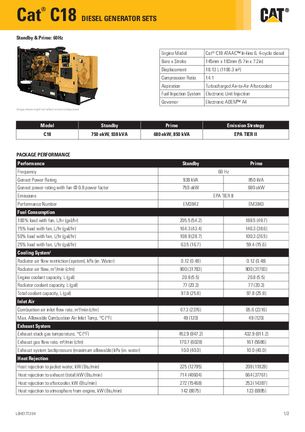
Cat C18 � DIESEL GENERATOR SETS

Standby & Prime: 60Hz

Image shown might not reflect actual configuration

Model C18

Standby 750 ekW, 938 kVA

Engine Model

Cat� C18 ATAACTM In-line 6, 4-cycle diesel

Bore x Stroke

145mm x 183mm (5.7in x 7.2in)

Displacement

18.13 L (1106.3 in�)

Compression Ratio 14:1

Aspiration

Turbocharged Air-to-Air Aftercooled

Fuel Injection System Electronic Unit Injection

Governor

Electronic ADEMTM A4

Prime 680 ekW, 850 kVA

Emission Strategy EPA TIER II

PACKAGE PERFORMANCE Performance Frequency Genset Power Rating Genset power rating with fan @ 0.8 power factor Emissions Performance Number Fuel Consumption 100% load with fan, L/hr (gal/hr) 75% load with fan, L/hr (gal/hr) 50% load with fan, L/hr (gal/hr) 25% load with fan, L/hr (gal/hr) Cooling System1 Radiator air flow restriction (system), kPa (in. Water) Radiator air flow, m3/min (cfm) Engine coolant capacity, L (gal) Radiator coolant capacity, L (gal) Total coolant capacity, L (gal) Inlet Air Combustion air inlet flow rate, m�/min (cfm) Max. Allowable Combustion Air Inlet Temp, �C (�F) Exhaust System Exhaust stack gas temperature, �C (�F) Exhaust gas flow rate, m�/min (cfm) Exhaust system backpressure (maximum allowable) kPa (in. water) Heat Rejection Heat rejection to jacket water, kW (Btu/min) Heat rejection to exhaust (total) kW (Btu/min) Heat rejection to aftercooler, kW (Btu/min) Heat rejection to atmosphere from engine, kW (Btu/min)

Standby
938 kVA 750 ekW
EM3842

60 Hz EPA TIER II

Prime
850 kVA 680 ekW
EM3843

205.5 (54.2) 164.3 (43.4) 108.9 (28.7) 63.5 (16.7)

188.5 (49.7) 146.3 (38.6) 100.3 (26.5) 59.4 (15.6)

0.12 (0.48) 900 (31783) 20.8 (5.5)
77 (20.3) 97.8 (25.8)

0.12 (0.48) 900 (31783) 20.8 (5.5)
77 (20.3) 97.8 (25.8)

67.3 (2376) 49 (120)

65.6 (2316) 49 (120)

452.9 (847.2) 170.7 (6028) 10.0 (40.0)

432.9 (811.2) 161 (5686) 10.0 (40.0)

225 (12795) 714 (40604) 272 (15468) 142 (8075)

208 (11828) 664 (37761) 253 (14387) 123 (6995)

LEHE1772-04

1/2

Cat C18 � DIESEL GENERATOR SETS

Emissions (Nominal)2 NOx, mg/Nm� (g/hp-hr) CO, mg/Nm� (g/hp-hr) HC, mg/Nm� (g/hp-hr) PM, mg/Nm� (g/hp-hr) Alternator3 Voltages Motor starting capability @ 30% Voltage Dip Current Frame Size Excitation Temperature Rise

Standby 2468 (5.42) 100.1 (0.22) 23.5 (0.06) 11.7 (0.03)

Prime 2213 (4.91) 75.6 (0.17) 24.1 (0.06) 10.6 (0.03)

208V 1917 skVA 2602.2 amps LC7224N
AREP 130 �C

220V 2129 skVA 2460.3 amps LC7224L
AREP 130 �C

240V 2501 skVA 2512 amps LC7224L
AREP 130 �C

480V 2512 skVA 1127.6 amps LC7224L
AREP 105 �C

600V 2512 skVA 902.1 amps LC7224L
AREP 130 �C

WEIGHTS & DIMENSIONS

C

Dim "A" mm (in) 3512 (138)

A Dim "B" mm (in)
1746 (69)

APPLICABLE CODES AND STANDARDS:
AS1359, CSA C22.2 No100-04, UL142, UL489, UL869, UL2200, NFPA37, NFPA70, NFPA99, NFPA110, IBC, IEC60034-1, ISO3046, ISO8528, NEMA MG1-22, NEMA MG1-33, 2006/95/EC, 2006/42/EC, 2004/108/EC. Note: Codes may not be available in all model configurations. Please consult your local Cat Dealer representative for availability.
STANDBY: Output available with varying load for the duration of the interruption of the normal source power. Average power output is 70% of the standby power rating. Typical operation is 200 hours per year, with maximum expected usage of 500 hours per year.
PRIME: Output available with varying load for an unlimited time. Average power output is 70% of the prime power rating. Typical peak demand is 100% of prime rated ekW with 10% overload capability for emergency use for a maximum of 1 hour in 12. Overload operation cannot exceed 25 hours per year
RATINGS: Ratings are based on SAE J1349 standard conditions. These ratings also apply at ISO3046 standard conditions.

B Dim "C" mm (in)
2322 (92)

Dry Weight kg (lb) 4863 (10721)

DEFINITIONS AND CONDITIONS
1 For ambient and altitude capabilities consult your Cat dealer. Air flow restriction (system) is added to existing restriction from factory.
2 Emissions data measurement procedures are consistent with those described in EPA CFR 40 Part 89, Subpart D & E and ISO8178-1 for measuring HC, CO, PM, NOx. Data shown is based on steady state operating conditions of 77� F, 28.42 in HG and number 2 diesel fuel with 35� API and LHV of 18,390 BTU/lb. The nominal emissions data shown is subject to instrumentation, measurement, facility and engine to engine variations. Emissions data is based on 100% load and thus cannot be used to compare to EPA regulations which use values based on a weighted cycle.
3 UL 2200 Listed packages may have oversized generators with a different temperature rise and motor starting characteristics. Generator temperature rise is based on a 40� C ambient per NEMA MG1-32.

LEHE1772-04 (05/20)

www.Cat.com/electricpower All rights reserved.
Materials and specifications are subject to change without notice.The International System of Units (SI) is used in this publication. � 2020 Caterpillar. All Rights Reserved. CAT, CATERPILLAR, LET'S DO THE WORK, their respective logos, "Caterpillar Corporate Yellow", the "Power Edge" and
Cat "Modern Hex" trade dress as well as corporate and product identity used herein, are trademarks of Caterpillar and may not be used without permission
2/2

Attachment

Pi cture shown may not reflect actual configuration
Full range of attachments
� Wide range of system expansion attachments, designed specifically to work with the EMCP 4
� Flexible packaging options for easy and cost effective installation
World wide product support
� Cat dealers provide extensive pre and post sale support
� Cat dealers have over 1,600 dealer branch stores operating in 200 countries
Features � A 33 x 132 pixel, 3.8 inch, white backlit graphical
display denotes text alarm/event descriptions, set points, engine and generator monitoring, and is visible in all lighting conditions. � Textual display with support for 26 languages
� Advanced engine monitoring is available on systems with an ADEMTM controller.
� Integration with the CDVR and IVR provides enhanced system performance
� Fully featured power metering, protective relaying, engine and generator parameter viewing, and expanded AC metering are all integrated into this controller.
� Real-time clock allows for date and time stamping of diagnostics and events in the control's logs as well as service maintenance reminders based on engine operating hours or calendar days. Up to 40 diagnostic events are stored in the non-volatile memory

EMCP 4.2B GENERATOR SET CONTROLLER
The Cat� EMCP 4.2B offers fully featured power metering, protective relaying and engine and generator control and monitoring. Engine and generator controls, diagnostics, and operating information are accessible via the control panel keypads; diagnostics from the EMCP 4 optional modules can be viewed and reset through the EMCP 4.2B.
Features � Ability to view and reset diagnostics on EMCP
4 optional modules via the control panel removes the need for a separate service tool for troubleshooting
� Set points and software stored in non-volatile memory, preventing loss during a power outage
� Five levels of security allow for configurable operator privileges
� Programmable security levels for groups of setpoints.
� Programmable kW Relays (3) � Programmable weekly exerciser timer � Dealer configurable resistive maps � Default overview screen � Real (kW) Load histogram � Auto mains failure � Programmable logic functionality � Selectable units
o Temperature: �C or �F o Pressure: psi, kPa, bar o Fuel Consumption: Liter/hr or Gal/hr
(U.S. or U.K.)

LEHE1208-01

1

Attachment

Standard Features
� Voltage (L-L, L-N) � Current (Phase) � Average Volt, Amp, Frequency � kW, kVAr, kVA (Average, Phase, %) � Power Factor (Average, Phase) � kW-hr, kVAr-hr (total) � Excitation voltage and current (with
CDVR) � Desired Voltage, Excitation Command,
Operating Mode (with IVR) � Generator stator and bearing temp (with
optional module) � kW load histogram
Generator Protection
� Generator phase sequence � Over/Under voltage (27/59) � Over/Under frequency (81 O/U) � Reverse Power (kW) (32) � Reverse Reactive Power (kVAr) (32RV) � Overcurrent (50/51) � Thermal Damage Curve
Engine Monitoring
� Coolant temperature � Oil pressure � Engine speed (RPM) � Battery voltage � Run hours � Crank attempt and successful start counter � Enhanced engine monitoring (with electronic
engines)
Engine Protection
� Control switch not in auto (alarm) � High coolant temp (alarm and shutdown) � Low coolant temp (alarm) � Low coolant level (alarm) � High engine oil temp (alarm and
shutdown) � Low, high, and weak battery voltage � Overspeed � Overcrank � Low Oil Pressure

Control
� Run / Auto / Stop control � Speed and voltage adjust � Local and remote emergency stop � Remote start/stop � Cycle crank
Inputs & Outputs
� Two dedicated digital inputs � Three analog inputs � Six programmable digital inputs � Eight relay out � Two programmable digital outputs
Communications
� Primary and accessory CAN data links � RS-485 annunciator data link � Modbus RTU (RS-485 Half duplex)
Language Support
Arabic, Bulgarian, Czech, Chinese, Danish, Dutch, English, Estonian, Finnish, French, German, Greek, Hungarian, Italian, Icelandic, Japanese, Latvian, Lithuanian, Norwegian, Polish, Portuguese, Romanian, Russian, Spanish, Swedish, Turkish
Environmental
� Control module operating temperature: -40�C to 70�C
� Display operating temperature: -20�C to 70�C � Humidity: 100% condensing 30�C to 60�C � Storage temperature: -40�C to 85�C � Vibration: Random profile, 24-1000 Hz, 4.3G rms
Standards � UL Recognized � CSA C22.2 No.100,14, 94 � Complies with all necessary standards for CE
Certification o 98/37/EC Machinery Directive o BS EN 60204-1 Safety of Machinery 89/336/EEC EMC Directive o BS EN 50081-1 Emissions Standard o BS EN 50082-2 Immunity Standard 73/23/EEC Low Voltage Directive o EN 50178 LVD Standard
� IEC529, IEC60034-5, IEC61131-3 � MIL STND 461

LEHE1208-01

2

ATTACHMENTS

ULCERT UL 2200 LISTING

INCLUDES THE FOLLOWING:
ALTERNATOR Alternator insulation system is UL Recognized (UL 1446). PMG and AREP alternators are available. Automatic voltage regulators are UL Recognized.
WIRE HARNESS AC, DC, and power harnesses are made with UL Listed wire and UL Listed terminals.
CONTROL PANEL Control panels are comprised of UL Listed and UL Recognized components. EMCP is UL Recognized.
CIRCUIT BREAKER Output circuit breaker is 100% rated and UL Listed.
TESTING All UL Listed sets are designed and rigorously tested in accordance with UL Standard for Safety, UL 2200.
LABELING Labeling meets UL requirements.
MECHANICAL OPTIONS Mechanical options do not require UL Listing and, therefore, are not affected. The exceptions to this are:

ELECTRICAL OPTIONS
The table below shows electrical options that meet UL requirements:

EBH EOS WCA1 WSS1 AH1H WHH GOVE5 FSS1 FSS2
FSS5 PBC5UL PBC10NU

Battery Heater Lube Oil Sump Heater Low Coolant Level Shutdown Low Coolant Temperature Alarm Anti-Condensation Heater Coolant Heater Electronic Governor (Fully Adjustable) Critical Low Fuel Level Shutdown Low Fuel Level Alarm
Critical High Fuel Alarm UL Listed Battery Charger NFPA Battery Charger, UL Listed

UL Listing is available on all diesel fuelled generator sets up to 175 kW at 60 Hz, 600 vac maximum.

FUEL TANKS
If a fuel tank is ordered with the unit, it must be UL Listed. Two versions are available: 24 hour integral (FCUL2) and 24/48 hour sub-base (FSBT)

ENCLOSURES
Factory installed enclosures meet UL requirements. Weatherproof and sound attenuated versions are available.

Materials and specifications are subject to change without notice.

CAT, CATERPILLAR, their respective logos, "Caterpillar Yellow," the "Power Edge" trade dress as well as corporate

and product identity used herein, are trademarks of Caterpillar and may not be used without permission.

www.Cat-ElectricPower.com

�2013 Caterpillar

LLEEHHEE0X41X0X-X00XX(0(10/113/1)3)

All Rights Reserved Printed in U.S.A.

Enclosures

C13/C15/C18 SOUND ATTENUATED ENCLOSURES
US Sourced Diesel Generator Set 350 - 750 ekW 60 Hz

Picture shown may not reflect actual configuration

Features
Robust/Highly Corrosion Resistant Construction � F actory installed on skid base � Environmentally friendly, polyester powder baked paint � 14 gauge steel � Interior zinc plated fasteners � Exterior stainless steel fasteners � Internally mounted exhaust silencing system � D esigned and tested to comply with UL 2200 Listed generator set
package � Compression door latches providing solid door seal
Excellent Access � Large cable entry area for installation ease � Accommodates side mounted single or multiple breakers � Three doors on both sides � V ertically hinged allow 180� opening rotation and retention with
door stays � L ube oil and coolant drains piped to the exterior of the enclosure
base � Radiator fill cover
Security and Safety � L ockable access doors which give full access to control panel and
breaker � Cooling fan and battery charging alternator fully guarded � Fuel fill, oil fill and battery can only be reached via lockable access � Externally mounted emergency stop button � Designed for spreader bar lifting to ensure safety � Stub-up area is rodent proof

Transportability These enclosures are of extremely rugged construction to withstand outdoor exposure and rough handling common on many construction sites.
Options � E nclosure constructed with 14 gauge steel � Enclosure constructed with 12 gauge aluminum (5052 grade) � Caterpillar yellow or white paint � Control panel viewing window � U L Listed integral fuel tank with 670, 400, and 300 gallon
capacities � U L Listed sub base fuel tank with 660, 1000, 1900, and 2200
gallon capacities. � S eismic certification per applicable building codes: IBC 2000, IBC
2003, IBC 2006, IBC 2009, IBC 2012, IBC 2015 CBC 2007, CBC 2010 � IBC Certification for 150 mph wind loading � AC/DC lighting package � 5 kW Canopy space heater to facilitate compliance with NFPA 110 � Motorized louvers and gravity discharge damper � 125A Load Center � GFCI outlets
*Not available with aluminum enclosures.

LEHE0465-09

1/7

Enclosures

Level 1 Sound Attenuated Enclosure (Steel) Sound Levels

Model C13 C15
C18

Standby eKW
350 400 350 400 450 500 550 600 650 700 750

Cooling Air Flow Rate

m3/s

cfm

8.5

18010

8.5

18010

10.4

22072

10.4

22072

10.4

22072

12.5

26415

8.1

17234

8.1

17234

12.7

26909

12.7

26909

12.7

26909

Ambient Capability*

�C

�F

57

135

56

133

59

138

51

124

46

115

48

118

45

113

43

109

51

123

48

118

48

118

Sound Attenuated Enclosure (Aluminum) Sound Levels

Model C13 C15
C18

Standby eKW
350 400 350 400 450 500 550 600 650 700 750

Cooling Air Flow Rate

m3/s

cfm

8.5

-

8.5

-

10.4

22072

10.4

22072

10.4

22072

12.5

26415

8.1

17234

8.1

17234

12.7

26909

12.7

26909

12.7

26909

Ambient Capability*

�C

�F

57

135

56

133

59

138

51

124

46

115

48

118

45

113

43

109

51

123

48

118

48

118

Sound Pressure Levels (dBA) at 7m (23 ft) 100% Load 74 75 73 73 74 75 75 75 75 75 75
Sound Pressure Levels (dBA) at 7m (23 ft) 100% Load 75 75 72 73 74 75 76 76 76 76 76

LEHE0465-09

2/7

Enclosures

Level 2 Sound Attenuated Enclosure (Steel) Sound Levels

Model

Standby eKW

Cooling Air Flow Rate

m3/s

cfm

Ambient Capability*

�C

�F

Sound Pressure Levels (dBA) at 7m (23 ft)
100% Load

350

7.2

15256

50

122

70

C13

400

7.2

15256

50

122

70

350

10.4

22071

50

122

72

400

10.4

22071

50

122

72

C15

450

10.4

22071

50

122

72

500

12.5

26415

50

122

72

*Cooling system performance at sea level. Consult your Cat� dealer for site specific ambient and altitude capabilities. Note: Sound level measurements are subject to instrumentation, installation and manufacturing variability, as well as ambient site conditions.

Component Weights to Calculate Package Weight

Model C13 C15
C18

Standby eKW
350 400 350 400 450 500 550 600 650 700 750

Narrow Skid Base

kg

lb

253

578

273

602

301

664

286

630

Wide Skid Base

kg

lb

579

1276

465

1025

466

1027

637

1404

Sound Attenuated Enclosure (Steel)

kg

lb

1245

2745

Sound Attenuated Enclosure (Aluminum)

kg

lb

765

1687

1245

2745

765

1687

1301

2868

817

1801

1393

3071

887

1955

Sound Attenuated Enclosure on Skid Base

Model C13 C15
C18

Standby eKW
350 400 350 400 450 500 550 600 650 700 750

Length "L"

mm

in

4948

194.8

4948

194.8

5183

204.0

5230

205.9

LEHE0465-09

Width "W"

mm

in

2014

79.3

2014

79.3

2014

79.3

2315

91.1

Height "H"

mm

in

2320

91.3

2320

91.3

2262

89.0

2253

88.7

3/7

Enclosures
Sound Attenuated Enclosure on a UL Listed Integral Fuel Tank Base

Model C13 C15
C18

Standby eKW
350 400 350 400 450 500 550 600 650 700 750

Length "L"

mm

in

5461

215.0

4948

194.8

5187

204.2

6977

274.7

Width "W"

mm

in

2014

79.3

2014

79.3

2014

79.3

2315

91.1

Height "H"

mm

in

2743

108.0

2619

103.0

2561

101.0

2675

105.3

LEHE0465-09

4/7

ATTACHMENTS

C13 / C15 / C18 Integral and Sub-Base Fuel Tanks
US Sourced Diesel Generator Set 350 - 750 ekW 60 Hz

Picture shown may not represent actual package

Features
� UL Listed for United States (UL 142) and Canada (CAN/ULC S601) � Facilitates compliance with NFPA 30 code, NFPA 37 and 110 standards and CSA C282 code � Dual wall � Lockable fuel fill cap, 4" (101.6 mm) NPT � Low fuel level warning standard, customer configurable warning or shutdown � Primary tank leak detection switch in containment basin � Tank design provides capacity for thermal expansion of fuel � Fuel supply dip tube is positioned so as not to pick up fuel sediment � Fuel return and supply dip tube is separated by an internal baffle to prevent immediate re-supply of
heated return fuel � Pressure washed with an iron phosphate solution � Interior tank surfaces coated with a solvent-based thin-film rust preventative � Heavy gauge steel gussets with internal lifting rings � Primary and secondary tanks are leak tested at 20.7 kPa (3 psi) minimum � Compatible with open packages and enclosures � Gloss black polyester alkyd enamel exterior paint � Welded steel containment basin (minimum of 110% of primary tank capacity) � Direct reading fuel gauge with variable electrical output � Emergency vents on primary and secondary tanks are sized in accordance with NFPA 30

Sub Base
� The sub-base fuel tank mounts below the generator set wide base

Integral
� Integral diesel fuel tank is incorporated into the generator set base frame � Robust base design includes linear vibration isolators between tank base and engine generator

Options

� Audio/visual fuel level alarm panel � 5 gal (18.9 L) spill containment � 5 gal (18.9 L) spill containment with fuel fill drop tube with in 6" (152 mm) from bottom of tank � 5 gal (18.9 L) spill containment with overfill prevention valve and fuel fill drop tube with in 6" (152 mm)
from bottom of tank � ULC Listed 7.5 gal (28.4 L) spill containment with vent extensions, vent whistle, and drop tube facilitating
compliance with CSA 8139-09 � ULC Listed 7.5 gal (28.4 L) spill containment with overfill prevention valve, vent extensions, vent whistle

and drop tube facilitating compliance with CSA 8139-09

LEHE0467-08

Page 1 of 5

ATTACHMENTS

Integral & Sub-Base Fuel Tank Base Useable Capacities with Fuel Tank Dimensions & Weights
Integral - Width (W) 2014 mm (79.3 in)

Sub-base - Width (W) 2056 mm (81.0 in)

Integral* - Width(W) 2315 mm (91.2 in) Sub-base*-Width(W) 2357 mm (92.7in) Open Set & Weather Protective Enclosure

C13 Tank Design

Feature Code

Total Capacity

Useable Capacity

Dry Weight

Liter Gallon Liter Gallon kg

lb

Tank Only Height 'H' mm in

Length 'L' mm in

Overall Package Height with Tank

Open

Enclosure

mm in mm in

Integral FTDW013 2646 699 2540 671 1569 3450 762 30.0 5461 215 2552 100.5 2743 108.0

Sub-Base FTDW005 3941 1041 3876 1024 1659 3657 635 25.0 5550 218.5 2763 108.8 2955 116.3

Sub-Base FTDW006 6980 1844 6818 1801 2228 4483 889 35.0 6184 243.5 3017 118.8 3209 126.3

Sub-Base FTDW007 8339 2203 8244 2178 2150 5052 889 35.0 7074 278.5 2291 117.8 3789 149.2

Sub-Base FTDW011 2476 654 2435 643 1468 3236 635 25.0 3810 150.0 2763 108.8 2955 116.3

C15 Tank Design

Feature Code

Total Capacity

Useable Capacity

Dry Weight

Liter Gallon Liter Gallon kg

lb

Integral FTDW002 1283 339 1262 333 1015 2237

Sub-Base FTDW005 3941 1041 3876 1024 1659 3657

Sub-Base FTDW006 6980 1844 6818 1801 2228 4912

Sub-Base FTDW008 2476 654 2435 643 1468 3236

Tank Only Height 'H' mm in 635 25.0 635 25.0 889 35.0 635 25.0

Length 'L'

Overall Package Height with Tank

Open

Enclosure

mm in mm in mm in

3814 150.1 2426 95.5 2619 103.0

5550 218.5 2763 108.8 2955 116.3

6184 243.5 3017 118.8 3209 126.3

3810 150.0 2763 108.8 2955 116.3

C18 Tank Design

Feature Code

Total Capacity

Useable Capacity

Dry Weight

Liter Gallon Liter Gallon kg

lb

Tank Only Height 'H' mm in

Length 'L' mm in

Overall Package Height with Tank

Open

Enclosure

mm in mm in

Integral FTDW004 1446 382 1422 376 1015 2237 635 25.0 3814 150.1 2426 95.5 2560 100.8

Integral* FTDW030 2498 660 2377 628 1681 3703 762 30.0 4995 196.6 2670 105.1 2675 105.3

Integral* FTDW031 5175 1367 4997 1320 2046 4510 762 30.0 6737 265.3 2670 105.1 2675 105.3

Sub-Base FTDW005 3941 1041 3876 1024 1659 3657 635 25.0 5550 218.5 2763 108.8 2955 116.3

Sub-Base FTDW007 8339 2203 8244 2178 2150 4134 889 35.0 7074 278.5 2291 117.8 3159 124.4

Sub-Base FTDW008 2476 654 2435 643 1468 3236 635 25.0 3810 150.0 2739 107.9 2905 114.4

Sub-Base* FTDW032 10228 2702 10112 2640 2638 5816 889 35.0 7368 290 3127 123.1 3132 123.3

LEHE0467-08

Page 2 of 5

ATTACHMENTS

Integral & Sub-Base Fuel Tank Base Useable Capacities with Fuel Tank Dimensions & Weights

Integral - Width(W) 2014 mm (79.3 in)

Sub-base - Width(W) 2056 mm (81 in) Integral* - Width(W) 2315 mm (91.2 in)

Sub-base*-Width(W) 2357 mm (92.7in)

Sound Attenuated Enclosure

C13 Tank Design

Feature Code

Total Capacity

Useable Capacity

Dry Weight

Liter Gallon Liter Gallon kg

lb

Integral FTDW013 2646 699 2540 671 1569 3450

Tank Only Height 'H' mm in 762 30.0

Length 'L'

Overall Package Height with Tank

Open

Enclosure

mm in mm in mm in

5461 215.0 NA NA 2743 108.0

Sub-Base FTDW005 3941 1041 3876 1024 1659 3657 635 25.0 5550 218.5 NA NA 2955 116.3

Sub-Base FTDW006 6980 1844 6818 1801 2033 4483 889 35.0 6184 243.5 NA NA 3209 126.3

Sub-Base FTDW007 8339 2203 8244 2178 2292 5052 889 35.0 7074 278.5 NA NA 3209 126.3

Sub-Base FTDW011 2476 654 2435 643 1468 3236 635 25.0 3810 150.0 NA NA 2955 116.3

C15 Tank Design

Feature Code

Total Capacity

Useable Capacity

Dry Weight

Liter Gallon Liter Gallon kg

lb

Integral FTDW001 1283 339 1262 333 1015 2237

Tank Only Height 'H' mm in 639 25.0

Length 'L'

Overall Package Height with Tank

Open

Enclosure

mm in mm in mm in

4746 186.9 NA NA 2619 103.0

Sub-Base FTDW005 3941 1041 3876 1024 1659 3657 635 25.0 5550 218.5 NA NA 2955 116.3

Sub-Base FTDW006 6980 Sub-Base FTDW011 2476

1844 654

6818 2435

1801 2228 4912 643 1468 3236

889 35.0 6184 243.5 NA 635 25.0 3810 150.0 NA

NA 3209 126.3 NA 2955 116.3

C18 Tank Design

Feature Code

Total Capacity

Useable Capacity

Dry Weight

Liter Gallon Liter Gallon kg

lb

Tank Only Height 'H' mm in

Length 'L' mm in

Overall Package Height with Tank

Open

Enclosure

mm in mm in

Integral FTDW003 1446 382 1422 376 1015 2237 635 25.0 3814 150.1 NA NA 2560 100.8

Integral* Integral*

FTDW030 2498 FTDW031 5175

660 2381 1367 4997

629 1681 3703 762 30.0 4995 196.6 2670 105. 2675 105.3 1
1320 2046 4510 762 30.0 6737 265.3 NA NA 2675 105.3

Sub-Base FTDW005 3941 Sub-Base FTDW007 8339

1041 2203

3876 8244

1024 1659 3657 2178 2150 4134

635 25.0 5550 218.5 NA 889 35.0 7074 278.5 NA

NA 2905 114.3 NA 3209 126.3

Sub-Base FTDW011 2476 654 2435 643 1468 3236 635 25.0 3810 150.0 NA NA 2905 114.3

Sub-Base* FTDW032 10228 2702 9994 2640 2638 5816 889 35.0 7368 290

NA NA 3132 123.3

LEHE0467-08

Page 3 of 5

ATTACHMENTS

The heights listed above do not include lumber used during manufacturing and shipping.

Estimated Run Times (Hours) at 100% Load

C13 Tank Design Integral Sub-Base Sub-Base Sub-Base Sub-Base

Feature Code FTDW013 FTDW005 FTDW006 FTDW007 FTDW011

Standby Ratings (ekW)

400

350

�

�

24

27

-

-

36

41

-

-

65

72

-

-

77

87

-

-

23

25

-

-

Prime Ratings (ekW)

350

320

�

�

25

29

-

-

38

43

-

-

72

77

-

-

81

93

-

-

24

27

-

-

C15 Tank Design
Integral Sub-Base Sub-Base Sub-Base

Feature Code
FTDW001 / FTDW002 FTDW005 FTDW006 FTDW008 / FTDW011

C18 Tank Design Integral Integral* Integral* Sub-Base Sub-Base Sub-Base Sub-Base*

Feature Code FTDW003 / FTDW004 FTDW030 FTDW031 FTDW005 FTDW007 FTDW008 / FTDW011 FTDW032

Standby Ratings (ekW)

500

450

400

350

9

9

11

11

28

29

32

36

50

52

57

63

17

18

20

22

Standby Ratings (ekW)

750

700 650

600

550

-

-

-

8

9

11

12

13

-

-

24

25

27

-

-

-

-

-

24

25

-

-

-

51

54

-

-

-

15

16

49

51

54

-

-

Prime Ratings (ekW)

455

410

365

320

10

10

11

12

30

31

35

38

54

56

62

67

19

20

22

24

Prime Ratings (ekW)

680

635

600

545

500

-

-

-

9

10

12

13

14

-

-

26

27

29

33

36

-

-

-

25

27

-

-

-

54

59

-

-

-

16

17

53

55

58

-

-

LEHE0467-08

Page 4 of 5

ATTACHMENTS
Tanks with full electrical stub-up area include removable end channel. Tanks with RH stub-up include stubup area directly below the circuit breaker or power terminal strips. Dimensions include weather-protective enclosure exhaust system. Dual wall sub-base tanks are UL Listed and constructed in accordance with UL Standard for Safety UL 142, Steel Aboveground Tanks for Flammable and Combustible Liquids and Canada CAN/ULC S601, Standard for Shop Fabricated Steel Aboveground Horizontal Tanks for Flammable and Combustible Liquids. Fuel tanks and applicable options facilitate compliance with the following United States NF PA Code and Standards: NFPA 30: Flammable and Combustible Liquids Code NFPA 37: Standard for the Installation and Use of Stationary Combustion Engines and Gas Turbines NFPA 110: Standard for Emergency and Standby Power Systems
Fuel tanks and applicable options facilitate compliance with the following Canadian Standard and Code: CSA C282 - Emergency Electrical Power Supply for Buildings CSA B139-09 - Installation Code for Oil-Burning Equipment
The following sub-base fuel tanks meet Chicago code for containment and labelling: FTDW005 FTDW008 FTDW011

LEHE0467-08 (03/20)

www.cat.com/electricpower
�2020 Caterpillar All rights reserved.

Circuit Breakers

C9 ACERTTM, C13 ACERT, C15 ACERT, C18 ACERT Circuit Breakers

Manually Operated Circuit Breakers

Current

Number Interrupting Ratings (kA rms) Trip (Lugs) Cable Size

(A) Frame of Poles 240V 480V 600V Units Range / Phase

Auxiliary Options

250 T4N

3

65

25

18

(1) 6 AWG � 350

kcmil

1 Form C + 1 Bell Alarm

400 T5N

3

65

25

18

Electronic

(2) 3/0 � 250 kcmil

250VAC/VDC

600 T6N

3

65

Construction robuste et durable

800 T6N

3

65

35 35

20

LS/I (S or I)
or

(3) 2/0 � 400 kcmil

Shunt Trip 24VDC

20

LSI

(3) 2/0 � 400 1 Form C + 1 Bell Alarm

kcmil

400VAC / 250VDC

1200 T7S

3

65

50

25

(4) 4/0 � 500 kcmil

Shunt Trip 24VDC

1600

R

3

65

35

18

BUS BAR

2000

R

3

65

35

18

Electronic LSI

BUS BAR

Form C (1NO + 1NC) Shunt Trip 24VDC

2500

R

3

65

35

18

BUS BAR

Electrically Operated Circuit Breakers

Current

Number Interrupting Ratings (kA rms) Trip (Lugs) Cable Size

(A) Frame of Poles 240V 480V 600V Units Range / Phase

800 T7M-S 3

65

50

25

Electronic

(4) 4/0 � 500 kcmil

1200 T7M-S 3

65

50

25

LSI

(4) 4/0 � 500

kcmil

Auxiliary Options
2 Form C + 1 Bell Alarm 24VDC
2 Form C + 1 Bell Alarm 24VDC

LEHE0942-01

Page 1 of 2

Circuit Breakers

Single Breaker Options (250 � 2500A)
Model C9 ACERTTM C9 ACERT C9 ACERT, C13 ACERT, C15 ACERT, C18 ACERT C9 ACERT, C13 ACERT, C15 ACERT, C18 ACERT C9 ACERT, C13 ACERT, C15 ACERT, C18 ACERT C13 ACERT, C15 ACERT, C18 ACERT C15 ACERT, C18 ACERT C18 ACERT

Current (A) 250 400 600 800 1200 1600 2000 2500

Operation Manually Operated Manually Operated Manually Operated Manually Operated or Electrically Operated Manually Operated or Electrically Operated Manually Operated Manually Operated Manually Operated

Multiple Breaker Options
Model C9 ACERT, C13 ACERT, C15 ACERT, C18 ACERT C9 ACERT, C13 ACERT, C15 ACERT, C18 ACERT C9 ACERT, C13 ACERT, C15 ACERT, C18 ACERT C9 ACERT, C13 ACERT, C15 ACERT, C18 ACERT C9 ACERT, C13 ACERT, C15 ACERT, C18 ACERT C13 ACERT, C15 ACERT, C18 ACERT C15 ACERT, C18 ACERT C18 ACERT

Main Breaker Box

Auxiliary Box

1st Breaker (Amps)

2nd Breaker (Amps)

Breaker (Amps)

Manually Operated
250

Manually Operated

Manually Operated

400

3rd Breaker:

600

250, 400, 600, 800, or 1200

250 or 400 (Not available if

800

1st & 2nd Breaker = 1200A)

1200

1600 2000 2500

Not Available

2nd Breaker: 250 or 400

LEHE0942-01 (04/16)

www.Cat-ElectricPower.com �2016 Caterpillar
All rights reserved.
Materials and specifications are subject to change without notice. CAT, CATERPILLAR, their respective logos, "Caterpillar Yellow", the "Power Edge" trade dress as well as corporate and product identity used herein, are trademarks of Caterpillar and may not be used without permission.

Battery Charger

Image Shown may not Reflect Actual Package.
Features
 Electronically current limited at 105% of rated output
 Alarm system  Digital display  Lightning and voltage transient protection  P rotection of connected equipment against
load dump protection  Constant voltage, current limited, 4-rate
automatic equalization  IP 20 housing  Temperature compensation  On board temperature sensor with remote port  Auto AC line compensation  Output regulated by sensed battery voltage

UL 10 Amp
Battery Charger
This battery charger offers accurate, automatic charging of lead-acid and nickel cadmium batteries. The output voltage automatically adjusts to changing input, load, battery and ambient conditions. This prevents battery over-charging and consequent loss of battery electrolyte.
Standard features include AC line compensation, precision voltage regulation, current limiting, automatic 2-rate charging, voltmeter and ammeter, temperature compensation and UL Listing.
The user interface is easy to understand with digital metering, NFPA 110 alarms and a battery fault alarm.
Standards
 C-UL listed to UL 1236  NFPA 70, NFPA 110  CSA 22.2 No 107 certified  CE DOC to EN 60335  IBC Seismic Certification

LEHE0141-05

Page 1 of 2

Battery Charger

Specifications

Input supply AC and DC fuses

110 � 120 V 208 � 240 V 2 input and 2 output)

Output voltage

24V

Output amps

10

Frequency

50 / 60 Hz

Operating temperature

-20�C ( -4�F) to +60�C (140�F)

Housing constructed of rustproof anodized Aluminum

Dimensions Width
195 mm (7.66 in)

Depth 165 mm (6.5 in)

Height 318 mm (12.5 in)

Weight 10.4 kg (23 lb)

NFPA 110 alarm package as follows:

 AC on

Green led (indication)

 AC fail

Red led and form C contact (2A)

 Float mode

LED

 Fast charge

LED

 Temp comp active LED

 Low battery volts Red led and Form C conta

 High Battery Volts Red led and Form C conta

 Charger fail

Red led and Form C conta

 Battery fault

Red led and Form C conta

 Battery disconnected

 Battery polarity reversed

 Mismatched charger battery voltage

 Open or high resistance charger to battery connection

 Open battery cell or excessive internal resistance

Feature Codes: BTC1024 BTC1028 BTC1035 BTC1025 BTC1032

Information contained in this publication may be considered confidential. Discretion is recommended when distributing. Materials and specifications are subject to change without notice.
CAT, CATERPILLAR, LET'S DO THE WORK, their respective logos, "Caterpillar Yellow," the "Power Edge" and Cat "Modern Hex" trade dress as well as corporate and product identity used herein, are trademarks of Caterpillar and may not be used without permission.

LEHE0141-05 (02/19)

www.cat,com/electricpower �2019 Caterpillar
All rights reserved.

ATTACHMENTS
Image Shown may not Reflect Actual Package

C15 and C18 Jacket Water x Remote pilot thermostat located on the engine for C15 and C18 Jacket Water optimized power cycle efficiency is factory set to Heater 100� F (37.8�C Heater x Automatically disconnected when the engine is . runnune control panel
Factory installed jacket water heater for increased cold-starting capability. The system includes a tankstyle metal heater with an integral high limit Fathcetormryoisntsattaallendd jaacrekemtowteateenrghienaetemrofuonr tiendcrceoansterdolcoldsttahretirnmgocsatapta,bdiluitrya.bTlehesislicyostneemhionscelusdaensdahteaantke-rsctyolentrol mreetlaalyhweairteedr twoitah caonminmteognraclohningehcltiimonit pthoeinrmt inostthaet and a rsceiolcomimcopoontmintmteroeoinzelhenpcodgaosinnefnoenserle.ammcTntoahidouxenhinmhetpeeauodatmientcertcorcionnaootnntrlhoadtrelnottthchl feoreleornrmlwmtaryoooaslswntptadaiarttenh,ldoeedcalut.aotrTiatnaihobgenleis hepaotwereranedffitchieenrmcyo.stat location is optimized for maximum coolant flow and heating power efficiency.

FEATURES
FACTORY INSTALLED
x Complete with silicone hoses x Isolated tank heater vibration and shock tested to
extreme limits to guarantee durability x Optimized location of the heater on the genset base
for maximum coolant flow x Remote pilot thermostat located on the engine for
optimized power cycle efficiency is factory set to 100� F (37.8�C) x Automatically disconnected when engine is running via a dedicated heater relay located in the control panel. x Supplied with UL recognized components x Compatible with Cat� ELC and all chemicals x All parts are serviceable and field replaceable x Incoloy heater element for longer service life

SPECIFICATIONS

Rating Frequency Phase Amps
Feature Code

Unit Specifications

Design Voltage

208

220

240

2250

2520

3000

50/60 Hz 50/60 Hz 50/60 Hz

1

1

1

10.82

11.45

12.5

JWH0058 JWH0059 JWHD032

LEHE0297-01

ATTACHMENTS
WIRING DIAGRAMS
Wiring diagram reference for 240V Line to Neutral power connection

Wiring diagram reference for 240V or 208V Line to Line and 120V Line to Neutral power connection (Note: Including Optional Space Heater and Battery Charger)

LEHE0297-01

2

ATTACHMENTS
HEATER DETAIL

HEATER OPERATION
The heater uses compliant components to UL and CSA, and is both CSA and UL approved.
When the generator set is not running, the heater is automatically connected to the AC supply through a power relay mounted in the control panel. Upon receiving a start signal, the AC supply is automatically disconnected by the power relay and automatically reconnected when the start signal is removed and the engine has stopped.
Pilot thermostat located on the engine precisely monitors and controls the engine coolant temperature and is wired to energize and de-energize heater power cycles.
A high-limit thermostat is built into the heater to regulate the output temperature to within safe limits.

Materials and specifications are subject to change without notice. CAT, CATERPILLAR, their respective logos, "Caterpillar Yellow," the "Power Edge" trade dress as well as corporate
and product identity used herein, are trademarks of Caterpillar and may not be used without permission.

www.Cat-ElectricPower.com

LEHE0297-01 (05/13) LEHE0297-01

�2013 Caterpillar All Rights Reserved.
Printed in U.S.A.
3

GENERATORS

GENERATOR ANTI-CONDENSATION HEATER AH1H
Appropriate when the generator set is to be sited in a low ambient and/or high humidity environment, the heater maintains the AC generator at a suitable temperature to prevent winding corrosion due to condensation.
The heater itself is powered by a 110/120 volt (VAC 120) or 208/240 volt (VAC 240) AC auxiliary supply protected by a fuse inside the main control panel. When the generator set is not running the heater is automatically connected to the AC supply through a power relay mounted in the control panel. Upon receiving a start signal the AC supply is automatically disconnected by the power relay and automatically reconnected when the start signal is removed and the engine has stopped.

Market: N. America LEHE4017 (01-05)

Information contained in this publication may be considered confidential. Discretion is recommended when distributing.
Materials and specifications are subject to change without notice.

www.cat-ElectricPower.com
� 2005 Caterpillar All Rights Reserved.
Printed in U.S.A.

Effective with sales to the first user on or after August 1, 2016

CATERPILLAR LIMITED WARRANTY

Industrial, Petroleum, Locomotive, and Agriculture Engine Products and Electric Power

Generation Products

Caterpillar Inc. or any of its subsidiaries ("Caterpillar") warrants new and remanufactured engines and new and rebuild electric power generation products sold by it (including any products of other manufacturers packaged and sold by Caterpillar), to be free from defects in material and workmanship.
This warranty does not apply engines sold for use in on-highway vehicle or marine applications; engines in machines manufactured by or for Caterpillar; C175, 3500 and 3600 series engines used in locomotive applications; 3000 Family engines, C0.5 through C4.4 and ACERTTM (C6.6, C7, C7.1, C9, C9.3, C11, C13, C15, C18, C27, and C32) engines used in industrial, mobile agriculture and locomotive applications; or Cat� batteries; or Electric Power Generation Products manufactured or assembled in India. These products are covered by other Caterpillar warranties.
This warranty is subject to the following:
Warranty Period
� For industrial engines, engines in a petroleum applications or Petroleum Power Systems (excluding petroleum fire pump application), or engines in a Locomotive application, or Uninterruptible Power Supply (UPS) systems, the warranty period is 12 months after date of delivery to the first user.
� For engines used in petroleum fire pump and mobile agriculture applications the warranty period is 24 months after date of delivery to the first user.
� For controls only (EPIC), configurable and custom switchgear products, and automatic transfer switch products, the warranty period is 24 months after date of delivery to the first user.
� For new CG132, CG170 and CG260 series power generation products the warranty period is 24 months/16,000 hours, whichever comes first, after date of delivery to first user.
� For electric power generation products other than CG132, CG170 and CG260 series in prime or continuous applications the warranty period is 12 months. For standby applications the warranty period is 24 months/1000 hours. For emergency standby applications the warranty period is 24 months/400 hours. All terms begin after date of delivery to the first user.
� For Caterpillar rebuild electric power generation products the warranty period is 12 months, but not to exceed 24 months from shipment of rebuilt electric power generation product from Caterpillar.
� For all other applications the warranty period is 12 months after date of delivery to the first user.

Worldwide
Caterpillar Responsibilities
If a defect in material or workmanship is found during the warranty period, Caterpillar will, during normal working hours and at a place of business of a Cat dealer or other source approved by Caterpillar:
� Provide (at Caterpillar's choice) new, Remanufactured, or Caterpillar approved repaired parts or assembled components needed to correct the defect.
Note: New, remanufactured, or Caterpillar approved repaired parts or assembled components provided under the terms of this warranty are warranted for the remainder of the warranty period applicable to the product in which installed as if such parts were original components of that product. Items replaced under this warranty become the property of Caterpillar.
� Replace lubricating oil, filters, coolant, and other service items made unusable by the defect.
� Provide reasonable and customary labor needed to correct the defect, including labor to disconnect the product from and reconnect the product to its attached equipment, mounting, and support systems, if required.
For new 3114, 3116, and 3126 engines and, new and Caterpillar rebuild electric power generation products (which includes the following: any new products of other manufacturers packaged and sold by Caterpillar)
� Provide travel labor, up to four hours round trip, if in the opinion of Caterpillar, the product cannot reasonably be transported to a place of business of a Cat dealer or other source approved by Caterpillar (travel labor in excess of four hours round trip, and any meals, mileage, lodging, etc. is the user's responsibility).
For all other products:
� Provide reasonable travel expenses for authorized mechanics, including meals, mileage, and lodging, when Caterpillar chooses to make the repair on-site.
User Responsibilities
The user is responsible for:
� Providing proof of the delivery date to the first user.
� Labor costs, except as stated under "Caterpillar Responsibilities," including costs beyond those required to disconnect the product from and reconnect the product to its attached equipment, mounting, and support systems.

� Travel or transporting costs, except as stated under "Caterpillar Responsibilities."
� Premium or overtime labor costs. � Parts shipping charges in excess of those that are usual and
customary. � Local taxes, if applicable. � Costs to investigate complaints, unless the problem is caused by a
defect in Caterpillar material or workmanship. � Giving timely notice of a warrantable failure and promptly making
the product available for repair. � Performance of the required maintenance (including use of proper
fuel, oil, lubricants, and coolant) and items replaced due to normal wear and tear. � Allowing Caterpillar access to all electronically stored data. Limitations Caterpillar is not responsible for: � Failures resulting from any use or installation that Caterpillar judges improper. � Failures resulting from attachments, accessory items, and parts not sold or approved by Caterpillar. � Failures resulting from abuse, neglect, and/or improper repair. � Failures resulting from user's delay in making the product available after being notified of a potential product problem. � Failures resulting from unauthorized repairs or adjustments, and unauthorized fuel setting changes. � Damage to parts, fixtures, housings, attachments, and accessory items that are not part of the engine, Cat Selective Catalytic Reduction System or electric power generation product (including any products of other manufacturers packaged and sold by Caterpillar). � Repair of components sold by Caterpillar that is warranted directly to the user by their respective manufacturer. Depending on type of application, certain exclusions may apply. Consult your Cat dealer for more information.
(Continued on reverse side...)

SELF5709

This warranty covers every major component of the products. Claims under this warranty should be submitted to a place of business of a Cat dealer or other source approved by Caterpillar. For further information concerning either the location to submit claims or Caterpillar as the issuer of this warranty, write Caterpillar Inc., 100 N. E. Adams St., Peoria, IL USA 61629.
Caterpillar's obligations under this Limited Warranty are subject to, and shall not apply in contravention of, the laws, rules, regulations, directives, ordinances, orders, or statutes of the United States, or of any other applicable jurisdiction, without recourse or liability with respect to Caterpillar.
A) For products operating outside of Australia, Fiji, Nauru, New Caledonia, New Zealand, Papua New Guinea, the Solomon Islands and Tahiti, the following is applicable:
NEITHER THE FOREGOING EXPRESS WARRANTY NOR ANY OTHER WARRANTY BY CATERPILLAR, EXPRESS OR IMPLIED, IS APPLICABLE TO ANY ITEM CATERPILLAR SELLS THAT IS WARRANTED DIRECTLY TO THE USER BY ITS MANUFACTURER.
THIS WARRANTY IS EXPRESSLY IN LIEU OF ANY OTHER WARRANTIES, EXPRESS OR IMPLIED, INCLUDING ANY WARRANTY OF MERCHANTABILITY OR FITNESS FOR A PARTICULAR PURPOSE, EXCEPT CATERPILLAR EMISSION-RELATED COMPONENTS WARRANTIES FOR NEW ENGINES, WHERE APPLICABLE. REMEDIES UNDER THIS WARRANTY ARE LIMITED TO THE PROVISION OF MATERIAL AND SERVICES, AS SPECIFIED HEREIN.
CATERPILLAR IS NOT RESPONSIBLE FOR INCIDENTAL OR CONSEQUENTIAL DAMAGES.
CATERPILLAR EXCLUDES ALL LIABILITY FOR OR ARISING FROM ANY NEGLIGENCE ON ITS PART OR ON THE PART OF ANY OF ITS EMPLOYEES, AGENTS OR REPRESENTATIVES IN RESPECT OF THE MANUFACTURE OR SUPPLY OF GOODS OR THE PROVISION OF SERVICES RELATING TO THE GOODS.
IF OTHERWISE APPLICABLE, THE VIENNA CONVENTION ON CONTRACTS FOR THE INTERNATIONAL SALE OF GOODS IS EXCLUDED IN ITS ENTIRETY.
For personal or family use engines or electric power generation products, operating in the USA, its territories and possessions, some states do not allow limitations on how long an implied warranty may last nor allow the exclusion or limitation of incidental or consequential damages. Therefore, the previously expressed exclusion may not apply to you. This warranty gives you specific legal rights and you may also have other rights, which vary by jurisdiction. To find the location of the nearest Cat dealer or other authorized repair facility, call (800) 447-4986. If you have questions concerning this warranty or its applications, call or write:
In USA and Canada: Caterpillar Inc., Engine Division, P. O. Box 610, Mossville, IL 61552-0610, Attention: Customer Service Manager, Telephone (800) 447-4986. Outside the USA and Canada: Contact your Cat dealer.
B) For products operating in Australia, Fiji, Nauru, New Caledonia, New Zealand, Papua New Guinea, the Solomon Islands and Tahiti, the following is applicable:
THIS WARRANTY IS IN ADDITION TO WARRANTIES AND CONDITIONS IMPLIED BY STATUTE AND OTHER STATUTORY RIGHTS AND OBLIGATIONS THAT BY ANY APPLICABLE LAW CANNOT BE EXCLUDED, RESTRICTED OR MODIFIED ("MANDATORY RIGHTS"). ALL OTHER WARRANTIES OR CONDITIONS, EXPRESS OR IMPLIED (BY STATUTE OR OTHERWISE), ARE EXCLUDED. WITHOUT LIMITING THE FOREGOING PROVISIONS OF THIS PARAGRAPH, WHERE A PRODUCT IS SUPPLIED FOR BUSINESS PURPOSES, THE CONSUMER GUARANTEES UNDER THE CONSUMER GUARANTEES ACT 1993 (NZ) WILL NOT APPLY.
NEITHER THIS WARRANTY NOR ANY OTHER CONDITION OR WARRANTY BY CATERPILLAR, EXPRESS OR IMPLIED (SUBJECT ONLY TO THE MANDATORY RIGHTS), IS APPLICABLE TO ANY ITEM CATERPILLAR SELLS THAT IS WARRANTED DIRECTLY TO THE USER BY ITS MANUFACTURER.
IF THE MANDATORY RIGHTS MAKE CATERPILLAR LIABLE IN CONNECTION WITH SERVICES OR GOODS, THEN TO THE EXTENT PERMITTED UNDER THE MANDATORY RIGHTS, THAT LIABILITY SHALL BE LIMITED AT CATERPILLAR'S OPTION TO (a) IN THE CASE OF SERVICES, THE SUPPLY OF THE SERVICES AGAIN OR THE PAYMENT OF THE COST OF HAVING THE SERVICES SUPPLIED AGAIN AND (b) IN THE CASE OF GOODS, THE REPAIR OR REPLACEMENT OF THE GOODS, THE SUPPLY OF EQUIVALENT GOODS, THE PAYMENT OF THE COST OF SUCH REPAIR OR REPLACEMENT OR THE ACQUISITION OF EQUIVALENT GOODS.

CATERPILLAR EXCLUDES ALL LIABILITY FOR OR ARISING FROM ANY NEGLIGENCE ON ITS PART OR ON THE PART OF ANY OF ITS EMPLOYEES, AGENTS OR REPRESENTATIVES IN RESPECT OF THE MANUFACTURE OR SUPPLY OF GOODS OR THE PROVISION OF SERVICES RELATING TO THE GOODS.
CATERPILLAR IS NOT LIABLE FOR INCIDENTAL OR CONSEQUENTIAL DAMAGES UNLESS IMPOSED UNDER MANDATORY RIGHTS.
IF OTHERWISE APPLICABLE, THE VIENNA CONVENTION ON CONTRACTS FOR THE INTERNATIONAL SALE OF GOODS IS EXCLUDED IN ITS ENTIRETY.
C) For products supplied in Australia:
IF THE PRODUCTS TO WHICH THIS WARRANTY APPLIES ARE:
I. PRODUCTS OF A KIND ORDINARILY ACQUIRED FOR PERSONAL, DOMESTIC OR HOUSEHOLD USE OR CONSUMPTION; OR
II. PRODUCTS THAT COST AUD 40,000 OR LESS,
WHERE THOSE PRODUCTS WERE NOT ACQUIRED FOR THE PURPOSE OF RE-SUPPLY OR FOR THE PURPOSE OF USING THEM UP OR TRANSFORMING THEM IN THE COURSE OF PRODUCTION OR MANUFACTURE OR IN THE COURSE OF REPAIRING OTHER GOODS OR FIXTURES, THEN THIS SECTION C APPLIES.
THE FOLLOWING MANDATORY TEXT IS INCLUDED PURSUANT TO THE AUSTRALIAN CONSUMER LAW AND INCLUDES REFERENCES TO RIGHTS THE USER MAY HAVE AGAINST THE DIRECT SUPPLIER OF THE PRODUCTS: OUR GOODS COME WITH GUARANTEES THAT CANNOT BE EXCLUDED UNDER THE AUSTRALIAN CONSUMER LAW. YOU ARE ENTITLED TO A REPLACEMENT OR REFUND FOR A MAJOR FAILURE AND COMPENSATION FOR ANY OTHER REASONABLY FORESEEABLE LOSS OR DAMAGE. YOU ARE ALSO ENTITLED TO HAVE THE GOODS REPAIRED OR REPLACED IF THE GOODS FAIL TO BE OF ACCEPTABLE QUALITY AND THE FAILURE DOES NOT AMOUNT TO A MAJOR FAILURE. THE INCLUSION OF THIS TEXT DOES NOT CONSTITUTE ANY REPRESENTATION OR ACCEPTANCE BY CATERPILLAR OF LIABILITY TO THE USER OR ANY OTHER PERSON IN ADDITION TO THAT WHICH CATERPILLAR MAY HAVE UNDER THE AUSTRALIAN CONSUMER LAW.
TO THE EXTENT THE PRODUCTS FALL WITHIN THIS SECTION C BUT ARE NOT OF A KIND ORDINARILY ACQUIRED FOR PERSONAL, DOMESTIC OR HOUSEHOLD USE OR CONSUMPTION, CATERPILLAR LIMITS ITS LIABILITY TO THE EXTENT IT IS PERMITTED TO DO SO UNDER THE AUSTRALIAN CONSUMER LAW TO, AT ITS OPTION, THE REPAIR OR REPLACEMENT OF THE PRODUCTS, THE SUPPLY OF EQUIVALENT PRODUCTS, OR THE PAYMENT OF THE COST OF SUCH REPAIR OR REPLACEMENT OR THE ACQUISITION OF EQUIVALENT PRODUCTS.
THE WARRANTY SET OUT IN THIS DOCUMENT IS GIVEN BY CATERPILLAR INC. OR ANY OF ITS SUBSIDIARIES, 100 N. E. ADAMS ST, PEORIA, IL USA 61629, TELEPHONE 1 309 675 1000, THE USER IS RESPONSIBLE FOR ALL COSTS ASSOCIATED WITH MAKING A CLAIM UNDER THE WARRANTY SET OUT IN THIS DOCUMENT, EXCEPT AS EXPRESSLY STATED OTHERWISE IN THIS DOCUMENT, AND THE USER IS REFERRED TO THE BALANCE OF THE DOCUMENT TERMS CONCERNING CLAIM PROCEDURES, CATERPILLAR RESPONSIBILITIES AND USER RESPONSIBILITIES.
TO THE EXTENT PERMISSIBLE BY LAW, THE TERMS SET OUT IN THE REMAINDER OF THIS WARRANTY DOCUMENT (INCLUDING SECTION B) CONTINUE TO APPLY TO PRODUCTS TO WHICH THIS SECTION C APPLIES.
�2016 Caterpillar All Rights Reserved. CAT, CATERPILLAR, their respective logos, "Caterpillar Yellow" the "Power Edge" trade dress as well as corporate and product identity used herein, are trademarks of Caterpillar and may not be used without permission.

SELF5709