Introducing your Xc1004 controller
Atlas Copco
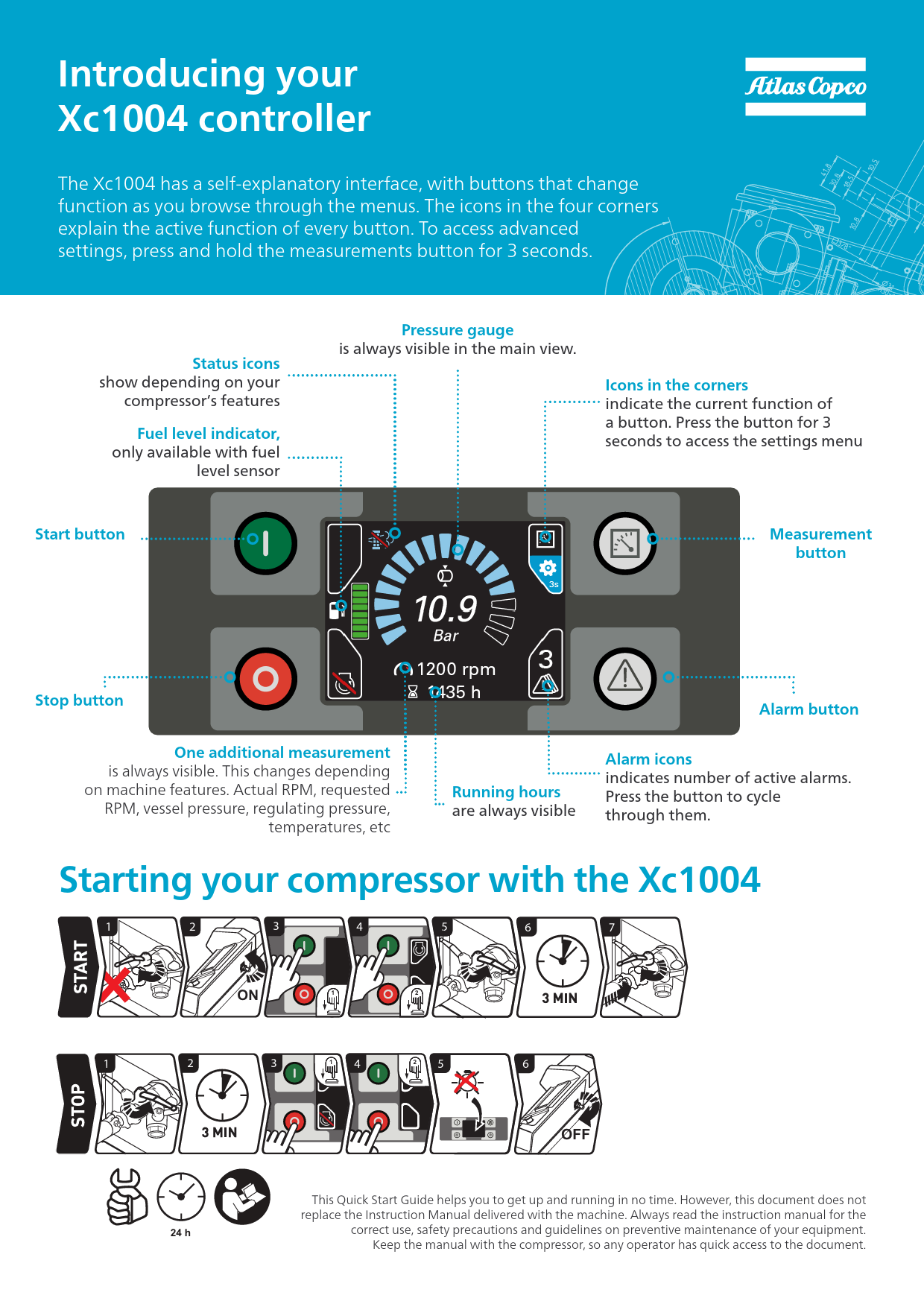
Introducing your Xc1004 controller
The Xc1004 features a self-explanatory interface with buttons that change function as you browse through the menus. The icons in the four corners explain the active function of every button. To access advanced settings, press and hold the measurements button for 3 seconds.
Controller Interface Overview
Status icons show depending on your compressor's features.
Fuel level indicator, only available with fuel level sensor.
Start button
Stop button
Pressure gauge is always visible in the main view.
Icons in the corners indicate the current function of a button. Press the button for 3 seconds to access the settings menu.
Measurement button
Alarm button
One additional measurement is always visible. This changes depending on machine features. Examples include Actual RPM, requested RPM, vessel pressure, regulating pressure, and temperatures.
Running hours are always visible.
Alarm icons indicate the number of active alarms. Press the button to cycle through them.
Controller Display Description: The central display shows '10.9 Bar' for pressure and '1200 rpm' with '435 h' for running hours. A large circular gauge with a needle indicates the current pressure. A smaller gauge shows engine speed. A battery symbol with a charge level is visible. A fuel level indicator is present, showing a nearly full tank. Three small icons are arranged vertically on the left: a green circle with a white 'I' [Status Active], a red circle with a white 'O' [Status Off], and a grey circle with a white '3' [Menu Option]. On the right, a circular icon with a white triangle inside a grey circle [Measurement Button Function] and a circular icon with a white bell inside a grey circle [Alarm Button Function] are shown. In the top corners of the display, small icons represent status indicators, such as a wrench for service interval, a warning triangle, and a battery symbol.
Starting your compressor with the Xc1004
START Sequence:
- [Step 1]: Press the [Start Button].
- [Step 2]: Controller display shows [ON].
- [Step 3]: A [3 MIN] delay is indicated.
- [Step 4]: A [24 h] indicator is shown.
- [Step 5]: Compressor starts.
- [Step 6]: Compressor running.
- [Step 7]: Compressor running.
STOP Sequence:
- [Step 1]: Press the [Stop Button].
- [Step 2]: A [3 MIN] delay is indicated.
- [Step 3]: Controller display shows [OFF].
- [Step 4]: A [24 h] indicator is shown.
- [Step 5]: Compressor stopped.
- [Step 6]: Compressor stopped.
This Quick Start Guide helps you get up and running quickly. However, this document does not replace the Instruction Manual delivered with the machine. Always read the instruction manual for correct use, safety precautions, and guidelines on preventive maintenance of your equipment. Keep the manual with the compressor so any operator has quick access to the document.
List of Most Common Alarm Codes
In case of an alarm or fault, your Xc1004 will display a orange or red banner with an alarm code and icon. A red banner indicates a shut-down, meaning the machine has stopped to protect the operator or the compressor. An orange banner indicates a warning.
This list shows the most common alarm codes and their meanings. If you encounter another code or have doubts, Atlas Copco service technicians are available to help.
This screen warns the operator of an issue with the engine coolant temperature.
| Icon | Number | Alarms | Icon | Number | Alarms |
|---|---|---|---|---|---|
| ⚠️ | General alarm icon | ⚠️ | 4050/4060 | Engine coolant temperature alarm | |
| ⚙️ | 1500/1521/1522 | Service interval | ⚠️ | 4070 | Engine coolant temperature sensor circuit |
| ⚠️ | 2000 | Emergency stop | ⚠️ | 4990 | VDO sensor circuit |
| ⚠️ | 2010 | Coolant temperature alarm | ⚠️ | 6309 | Engine preheat failure |
| ⚠️ | 2020 | Engine oil pressure alarm | ⚠️ | 6327 | Start failure |
| ⚠️ | 2030 | Engine coolant level | ⚠️ | 6420 | Stop failure |
| ⚠️ | 2040 | Compressor element temperature | ⚠️ | 6427 | Run failure |
| ⚠️ | 3000/3010 | Fuel level alarm | ⚠️ | 7000 | ECU communication error |
| ⚠️ | 3050/3060 | High vessel pressure alarm | ⚠️ | 7006 | Mall function indicator lamp |
| ⚠️ | 3080 | Vessel pressure sensor circuit | ⚠️ | 7007/7008/7009 | ECU red/amber/protect lamp |
| ⚠️ | 3130 | Regulating pressure sensor circuit | ⚠️ | 7020 | Engine Speed alarm |
| ⚠️ | 3450/3460 | Battery low/high alarm | ⚠️ | 7030 | ECU engine coolant temperature alarm |
| ⚠️ | 4000/4010/4020 | LP Element temperature alarm | ⚠️ | 7040 | ECU engine oil pressure alarm |
| ⚠️ | 4040 | LP Element temperature sensor circuit | ⚠️ | 7150/7160 | DEF tank level 1/level 2 |


