APX™ 8500 All-band P25 Mobile Radio - Motorola Solutions Asia Pacific
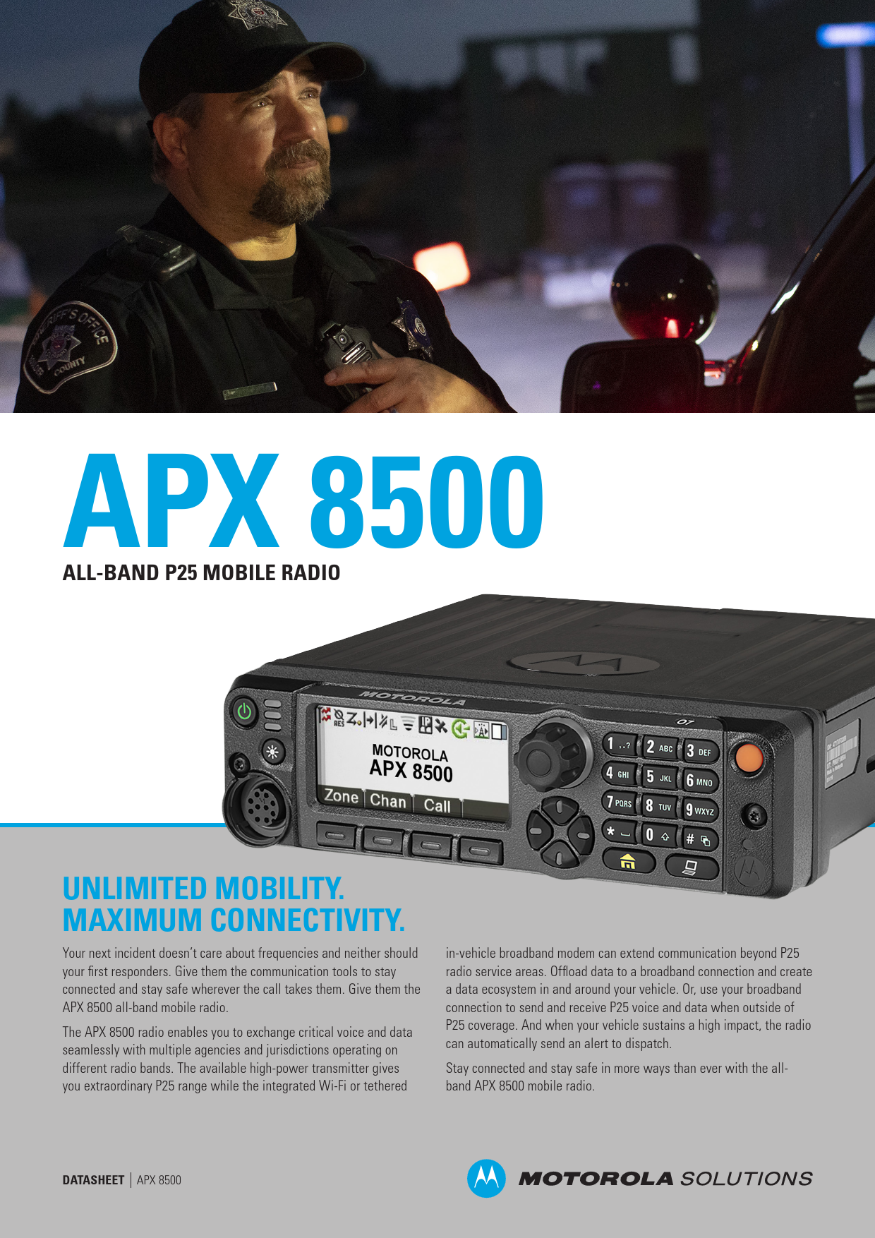
APX 8500 ALL-BAND P25 MOBILE RADIO UNLIMITED MOBILITY. MAXIMUM CONNECTIVITY. Your next incident doesn't care about frequencies and neither should your first responders. Give them the communication tools to stay connected and stay safe wherever the call takes them. Give them the APX 8500 all-band mobile radio. The APX 8500 radio enables you to exchange critical voice and data seamlessly with multiple agencies and jurisdictions operating on different radio bands. The available high-power transmitter gives you extraordinary P25 range while the integrated Wi-Fi or tethered in-vehicle broadband modem can extend communication beyond P25 radio service areas. Offload data to a broadband connection and create a data ecosystem in and around your vehicle. Or, use your broadband connection to send and receive P25 voice and data when outside of P25 coverage. And when your vehicle sustains a high impact, the radio can automatically send an alert to dispatch. Stay connected and stay safe in more ways than ever with the allband APX 8500 mobile radio. DATASHEET APX 8500 ALL-BAND CONNECTIVITY ALL BANDS. NO BOUNDARIES. With a 4-in-1 mobile radio and an all-band antenna, you now have the ability to stay connected and expand communications across multiple agencies with one device. Extend your reach further with an available high-power transmitter and communicate with widely dispersed teams across different bands. BUILT-IN Wi-Fi VOICE AND DATA, ALL AT ONCE Packed with all the connections you need, the APX 8500 keeps your team in touch and within reach of over-the-air updates. Receive new codeplugs, firmware updates and software features at the speed of Wi-Fi-- without interruptions to voice communications. RF antenna port GPS Wi-Fi Accessory connector DC power DESIGNED TO SECURE AND PROTECT KEEP VOICE AND DATA PROTECTED The APX 8500 secures voice and data using multiple hardware encryption algorithms and the ability to rekey over the air, so it's protected from scanners and eavesdroppers. What's more, P25 Radio Authentication ensures only valid users can access the system while the available two-factor authentication secures database logins. DEVICE MANAGEMENT SERVICES ALL THE SUPPORT YOU NEED Motorola Solutions offers three levels of service plans Essential, Advanced and Premier. From simple support for technical troubleshooting to a complete transfer of optimization and maintenance services to Motorola Solutions, you choose the level of support that suits you best. DATASHEET APX 8500 PAGE 2 O2 CONTROL HEAD EXTREME USABILITY The O2 control head provides rugged simplicity for efficient and confident communication. Extreme controls with easy to read color display and a built-in 7.5 watt speaker provides clear visual and audible user experiences. Available in high impact green or black. Exaggerated design and rugged housing for extreme environments Full color display with night mode and intelligent lighting Integrated high density speaker for loud, clear audio Programmable buttons all around Programmable multi-select buttons Enlarged multifunction channel / volume knob O3 HANDHELD CONTROL HEAD HANDHELD FLEXIBILITY The O3 corded control head fits all your mobile controls in your hand. With the O3 your radio controls are never out of reach. Full color display with intelligent lighting Programmable menu buttons Dedicated volume and channel rockers Fully integrated DTMF keypad Integrated control head and microphone design APX 8500 CONTROL HEADS1 Dedicated volume and channel knobs for quick control Easy to read, anti-reflective color display Full color display with night mode and intelligent lighting Multi-function channel / volume knob Programmable menu buttons E5 CONTROL HEAD UNMATCHED READABILTY. OPTIMIZED USABILITY. A bright color display and intelligent lighting makes the E5 easy to read under any condition while the optimized tactility and button placement reduces inadvertent actuations. DATASHEET APX 8500 Programmable multi-select buttons Integrated controls for siren and lights, PA and gunlock or DTMF keypad O7 CONTROL HEAD INTEGRATED MULTI-FUNCTIONALITY The O7 is a sophisticated control head with a color display and built-in keypad. It can integrate your radio vehicle control into a single ergonomic interface and supports dual radio installations. 1 Compatible O9 control head not shown. PAGE 3 FEATURES OPERATION MODES Digital Trunking: 9600 Baud APCO P25 Phase 1 FDMA and Phase 2 TDMA Digital Conventional: APCO 25 Analog Trunking: 3600 Baud SmartNet, SmartZone, Omnilink Analog Conventional: MDC 1200 ASTRO® 25 Integrated Voice and Data SmartConnect Multi-net Connectivity2 FREQUENCY BANDS All-band: Simultaneous Operation in VHF, UHF Range 1, UHF Range 2, 700 and 800 MHz Bands 100 Watt High-Power available in VHF and UHF Range 1 bands (High-Power model only) Up to 3,000 Channels ADDITIONAL CONNECTIVITY Wi-Fi 802.11 b/g/n2 Data Modem Tethering2 MANAGEMENT Radio Management Customer Programming Software LOCATION-TRACKING Integrated GPS/GLONASS for Outdoor Location Tracking Mission-Critical Geofence2 SECURITY 265-bit AES, ADP, DES, DVP2 FIPS 140-2 Level 3, FIPS 197 P25 Authentication2 Multikey for 128 keys and Multi-algorithm2 Over-The-Air-Rekeying (OTAR)2 USER INTERFACE O7 Multi Functional Control Head E5 Enhanced Control Head O3 Handheld Control Head O2 Extreme Usability Control Head Supports the discontinued O9 Control Head and the O5 Control Head OTHER FEATURES Intelligent Priority Scan Instant Recall Impact Detection2 Intelligent Lighting Tactical Inhibit2 Digital Tone Signaling2 12 Character RFID Asset Tracking2 ViQi Virtual Partner2 2Optional Feature DATASHEET APX 8500 PAGE 4 DIMENSIONS AND WEIGHT O7 Control Head - Remote Mount E5 Control Head - Remote Mount O2 Control Head - Remote Mount Mid Power Radio Transceiver and O7 Control Head - Dash Mount Mid Power Radio Transceiver and E5 Control Head - Dash Mount Mid Power Radio Transceiver and O5 Control Head - Dash Mount Mid Power Radio Transceiver and O2 Control Head - Dash Mount Mid Power Radio Transceiver and Remote Mount High Power Radio Transceiver and Remote Mount Dimensions (H x W x D) 51 x 178 x 81mm (2.0 x 7.0 x 3.2 in) 51 x 178 x 79 mm (2.0 x 7.0 x 3.1 in) 68 x 206 x 96 mm (2.7 x 8.1 x 3.8 in) 51 x 178 x 256 mm (2.0 x 7.0 x 10.1 in) 51 x 178 x 255 mm (2.0 x 7.0 x 10.0 in) 51 x 178 x 250 mm (2.0 x 7.0 x 9.8 in) 68 x 206 x 271 mm (2.7 x 8.1 x 10.7 in) 51 x 178 x 232 mm (2.0 x 7.0 x 9.1 in) 88 x 248 x 320 mm (3.4 x 9.7 x 12.6 in) Weight - 3.1 kg (6.8 lbs) 3.1 kg (6.8 lbs) 3.1 kg (6.8 lbs) 3.3 kg (7.23 lbs) 2.9 kg (6.4 lbs) 8.0 kg (17.6 lbs) 248mm APX 8500 High-Power Model Shown 88mm DATASHEET APX 8500 320mm 248mm PAGE 5 PERFORMANCE AND REGULATORY TRANSMITTER- TYPICAL PERFORMANCE SPECIFICATIONS VHF Frequency Range Band Splits 136-174 MHz Channel Spacing Maximum Frequency Separation 30/25/12.5 kHz Full Bandsplit Rated RF Output Power3 (Adjustable) 1-50 W (Mid Power) 1-100 W (High Power) Frequency Stability3 (-30°C to +85°C; +25°C Ref.) ±0.8 PPM Modulation Limiting ±5/±2.5 kHz Modulation Fidelity (C4FM) 12.5 kHz Digital Channel Emissions3 Audio Response3 FM Hum & Noise3 (25 kHz / 12.5 kHz) Audio Distortion3 (25 & 20 kHz / 12.5 kHz) 1.10% Conducted Radiated -85 dBc -20 dBm +1, -3 dB (EIA) 53 dB/ 52 dB 0.50% / 0.50% UHF R1 380-470 MHz 25/20/12.5 kHz Full Bandsplit 1-40 W (Mid Power) 1-100 W (High Power) ±0.8 PPM ±5/±2.5 kHz 1.10% Conducted Radiated -85 dBc -20 dBm +1, -3 dB (EIA) 53 dB/ 50 dB 0.50% / 0.50% UHF R2 450-520 MHz 25/20/12.5 kHz Full Bandsplit 1-45 W (450-485 MHz) 1-40 W (485-512 MHz) 1-25 W (512-520 MHz) ±0.8 PPM ±5/±2.5 kHz 1.10% Conducted Radiated -85 dBc -20 dBm +1, -3 dB (EIA) 53 dB/ 50 dB 0.50% / 0.50% 700 MHz 764-776, 794-806 MHz 806-825, 851-870 MHz 25/20/12.5 kHz Full Bandsplit 800 MHz 764-776, 794-806 MHz 806-825, 851-870 MHz 25/20/12.5 kHz Full Bandsplit 1-30 W 1-35 W ±0.8 PPM ±0.8 PPM ±5/±2.5 kHz ±5/±4 (NPSPAC) /±2.5 kHz 1.10% 1.10% Conducted Radiated -75/-85 dBc -20/-40 dBm +1, -3 dB (EIA) 50 dB/ 48 dB 0.50% / 0.50% Conducted Radiated -75 dBc -20 dBm +1, -3 dB (EIA) 50 dB/ 48 dB 0.50% / 0.50% RECEIVER - TYPICAL PERFORMANCE SPECIFICATIONS VHF Frequency Range Band Splits 136-174 MHz Channel Spacing Minimum Frequency Separation Audio Output Power 3% distortion, 8/3.2 Ohm speakers Frequency Stability1 (-30 °C to +85 °C; +25 °C Ref.) Analog Sensitivity3 (12 dB SINAD) Digital Sensitivity (5% BER) Intermodulation Rejection (12.5 kHz / 25 kHz) Spurious Rejection Audio Response3 Audio Distortion at rated3 Selectivity3 (12.5 kHz / 25 kHz / 30 kHz) 30/20/12.5 kHz Full Bandsplit 7.5 W/15 W ±0.8 PPM Pre-Amp -123 dBm (0.158 V) Standard -119 dBm (0.251 V) -123 dBm (0.158 V) -119 dBm (0.251 V) Pre-Amp 84 dB / 85 dB Standard 86 dB / 96 dB 90 dB +1, -3 dB (EIA) 1.20% 76 dB 87 dB 90 dB UHF R1 380-470 MHz 25/20/12.5 kHz Full Bandsplit 7.5 W/15 W ±0.8 PPM Pre-Amp -123 dBm (0.158 V) Standard -119 dBm (0.251 V) -123 dBm -119 dBm (0.158 V) (0.251 V) Pre-Amp 82 dB / 83 dB Standard 86 dB / 86 dB 90 dB +1, -3 dB (EIA) 1.20% 76 dB 82 dB - UHF R2 450-520 MHz 25/20/12.5 kHz Full Bandsplit 7.5 W/15 W ±0.8 PPM Pre-Amp -123 dBm (0.158 V) Standard -119 dBm (0.251 V) -123 dBm -119 dBm (0.158 V) (0.251 V) Pre-Amp 82 dB / 83 dB Standard 86 dB / 86 dB 90 dB +1, -3 dB (EIA) 1.20% 76 dB 82 dB - 700 MHz 764-776 MHz 799-806 MHz 25/20/12.5 kHz Full Bandsplit 7.5 W/15 W 800 MHz 851-870 MHz 25/20/12.5 kHz Full Bandsplit 7.5 W/15 W ±0.8 PPM ±0.8 PPM -121 dBm (0.199 V) -123 dBm (0.158 V) -120 dBm (0.224 V) -121 dBm (0.199 V) -120 dBm -121.5 dBm (0.188 (0.224 V) V) 85 dB / 85 dB 85 dB / 85 d 100 dB +1, -3 dB (EIA) 1.20% 72 dB 82.5 dB - 100 dB +1, -3 dB (EIA) 1.20% 72 dB 82.5 dB - POWER AND BATTERY DRAIN Frequency Range Band Splits VHF 136-174 MHz UHF R1 380-470 MHz RF Power Output 1-50 W (mid-power) 1-100 W (high-power) 10-40 W (mid-power) 1-100 W (high-power) Operation Standby at 13.8 V Receive Current at Radio Audio at 13.8 V Transmit Current at Rated Power (mid-power) Transmit Current at Rated Power (high-power) 13.8 V DC ±20% Negative Ground 1.4 A 3.2 A 8 A @ 15 W 15 A @ 50W 8 A @ 15 W 30 A @ 40 W 13.8 V DC ±20% Negative Ground 1.4 A 3.2 A 8 A @ 15 W 15 A @ 40W 8 A @ 15 W 30 A @ 45 W 3 Measured in the analog mode per TIA / EIA 603 single-tone method under nominal conditions. UHF R2 450-520 MHz 700 MHz 764-775, 794-806 MHz 1-45 W (450-485 MHz) 1-40 W (485-512 MHz) 1-25 W (512-520 MHz) 13.8 V DC ±20% Negative Ground 1.4 A 3.2 A 8 A @ 15 W 13 A @ 45W 1-35 W 13.8 V DC ±20% Negative Ground 1.4 A 3.2 A 8 A @ 15 W 15 A @ 50W - - 800 MHz 806-825, 851-870 MHz 1-35 W 13.8 V DC ±20% Negative Ground 1.4 A 3.2 A 8 A @ 15 W 13 A @ 50W - DATASHEET APX 8500 PAGE 6 LOCATION - TRACKING Channels Tracking Sensitivity Accuracy4 Cold Start Hot Start Mode of Operation FCC/IC TYPE ACCEPTANCE FCC/IC ID FCC ID: AZ492FT7089 IC ID: 109U-92FT7089 FCC ID: AZ492FT7118 IC: N/A 12 -164 dBm <5 meters (95%) <60 seconds (95%) <5 seconds (95%) Autonomous (Non-Assisted) GNSS or SBAS Band and Power Level 764-776 MHz (10-30 W) 794-806 MHz (10-30 W) 806-824 MHz (10-35 W) 851-870 MHz (10-35 W) 136-174 MHz (10-50 W) 380-470 MHz (10-40 W) 450-485 MHz (10-45 W) 485-512 MHz (10-40 W) 512-520 MHz (10-25 W) 136-174 MHz (1-100 W) 380-470 MHz (1-100 W) ENCRYPTION Supported Encryption Algorithms Encryption Algorithm Capacity Encryption Keys per Radio Encryption Frame Re-sync Interval Encryption Keying Synchronization Vector Generator Encryption Type Key Storage Key Erasure Standards 256-bit AES, ADP, DES, DES-XL,DES-OFB, DVP-XL 8 Module capable of storing 1024 keys. Programmable for 128 Common Key Reference (CKR) or 16 Physical Identifier (PID) P25 CAI 300 mSec Key Loader XL Counter Addressing OFB Output Feedback National Institute of Standards and Technology (NIST) approved random number generator Digital Tamper protected volatile or non-volatile memory Keyboard command and tamper detection FIPS 140-2 Level 3, FIPS 197 ENVIRONMENTAL SPECIFICATIONS Operating Temperature Storage Temperature Humidity ESD Water & Dust Intrusion -30ºC/+60ºC -40ºC/+85ºC Per MIL-STD IEC 801-2 KV IP56 RADIO MODEL NUMBERS APX 8500 All Band Mobile APX 8500 All Band Mid Power High Power M37TSS9PW1AN M37TXS9PW1AN 4 Measured conductivity with >6 satellites visible at a nominal -130 dBm signal strength. DATASHEET APX 8500 PAGE 7 MOBILE MILITARY STANDARDS 810, C, D, E, F & G MIL-STD 810C MIL-STD 810D Method Proc./Cat. Method Proc./Cat. Low Pressure 500.1 I 500.2 II High Temperature 501.1 I, II 501.2 I/A1, II/A1 Low Temperature 502.1 I 502.2 I/C3, II/C1 Temperature Shock 503.1 I Proc 503.2 1/A1C3 Solar Radiation 505.1 II 505.2 I Rain 506.1 I, II 506.2 I, II Humidity 507.1 II 507.2 II Salt Fog 509.1 I Proc 509.2 I Proc Blowing Dust 510.1 I 510.2 I, II Vibration 514.2 VIII/F, Curve-W 514.3 I/10, II/3 Shock 516.2 I, III, V 516.3 I, V, VI MIL-STD 810E Method Proc./Cat. 500.3 II 501.3 I/A1, II/A1 502.3 I/C3, II/C1 503.3 1/A1C3 505.3 506.3 507.3 509.3 510.3 514.4 516.4 I I, II II I Proc I, II I/10, II/3 I, V, VI MIL-STD 810F Method Proc./Cat. 500.4 I/II 501.4 I/Hot, II/Hot 502.4 I/C3, II/C1 503.4 I 505.4 506.4 507.4 509.4 510.4 514.5 516.5 I I, III I Proc I Proc I, II I/24 I, V, VI MIL-STD 810G Method Proc./Cat. 500.5 II 501.5 I/A1, II/A1 502.5 I/C3, II/C1 503.5 I/C 505.5 506.5 507.5 509.5 510.5 514.6 516.6 I/A1 I, III II/Aggravated I Proc I, II I/24 I, V, VI For more information, please visit us on the web at: www.motorolasolutions.com/APX Motorola Solutions Ltd. Nova South, 160 Victoria Street, London, SW1E 5LB, United Kingdom. MOTOROLA, MOTO, MOTOROLA SOLUTIONS and the Stylized M Logo are trademarks or registered trademarks of Motorola Trademark Holdings, LLC and are used under license. All other trademarks are the property of their respective owners. © 2020 Motorola Solutions, Inc. All rights reserved. (09-20)Adobe PDF Library 15.0