Extron SSP 200 Setup Guide
The Extron SSP 200 is a high-performance surround sound processor that automatically decodes Dolby®, DTS®, and PCM formats from digital input sources to discrete audio outputs. Providing up to ten built-in balanced analog outputs, the SSP 200 offers flexibility for pro A/V applications in corporate, commercial, and education environments. It supports immersive formats like Dolby Atmos and DTS:X, as well as legacy Dolby and DTS formats. An upmix function synthesizes exceptional multichannel audio from stereo content. The SSP 200 features an HDMI input with loop through, coaxial and optical digital inputs, and an analog stereo input. It is designed for integration into pro A/V installations, featuring a compact, half-rack metal enclosure, RS-232 serial and LAN control, and balanced line level outputs.
This guide provides instructions for an experienced user to set up and configure the SSP 200. It covers connecting other devices and performing basic operations using rear panel connections and front panel controls. For full operation and configuration through Extron Product Configuration Software (PCS), internal web pages, and Simple Instruction Set (SIS™) commands, refer to the SSP 200 User Guide.
NOTE: For information while using PCS, see the SSP 200 PCS Help File.
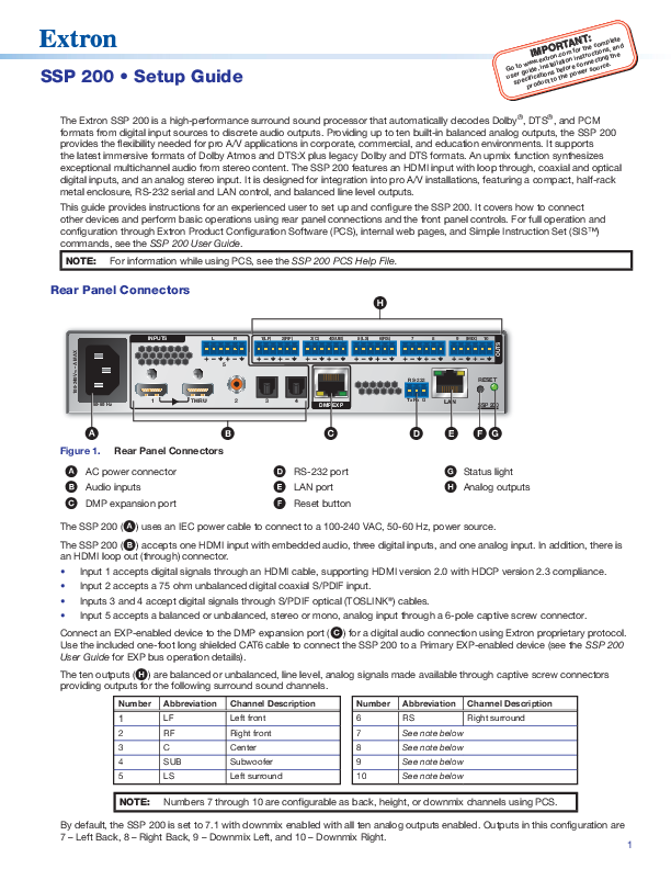
Rear Panel Connectors
Figure 1 illustrates the rear panel connectors. Key components include:
- A AC power connector
- B Audio inputs
- C DMP expansion port
- D RS-232 port
- E LAN port
- F Reset button
- G Status light
- H Analog outputs
The SSP 200 (A) uses an IEC power cable to connect to a 100-240 VAC, 50-60 Hz power source.
The SSP 200 (B) accepts one HDMI input with embedded audio, three digital inputs, and one analog input. It also features an HDMI loop out (through) connector.
- Input 1 accepts digital signals through an HDMI cable, supporting HDMI version 2.0 with HDCP version 2.3 compliance.
- Input 2 accepts a 75 ohm unbalanced digital coaxial S/PDIF input.
- Inputs 3 and 4 accept digital signals through S/PDIF optical (TOSLINK®) cables.
- Input 5 accepts a balanced or unbalanced, stereo or mono, analog input through a 6-pole captive screw connector.
Connect an EXP-enabled device to the DMP expansion port (C) for a digital audio connection using Extron proprietary protocol. Use the included one-foot long shielded CAT6 cable to connect the SSP 200 to a Primary EXP-enabled device (see the SSP 200 User Guide for EXP bus operation details).
The ten outputs (H) are balanced or unbalanced, line level, analog signals made available through captive screw connectors, providing outputs for the following surround sound channels:
| Number | Abbreviation | Channel Description | Number | Abbreviation | Channel Description |
|---|---|---|---|---|---|
| 1 | LF | Left front | 6 | RS | Right surround |
| 2 | RF | Right front | 7 | See note below | |
| 3 | C | Center | 8 | See note below | |
| 4 | SUB | Subwoofer | 9 | See note below | |
| 5 | LS | Left surround | 10 | See note below |
NOTE: Numbers 7 through 10 are configurable as back, height, or downmix channels using PCS. By default, the SSP 200 is set to 7.1 with downmix enabled, with all ten analog outputs enabled. Outputs in this configuration are 7 - Left Back, 8 - Right Back, 9 – Downmix Left, and 10 – Downmix Right.
Mounting and Cabling
Step 1: Mount the device
a. Turn off or disconnect all equipment power sources.
b. Mount the SSP 200 using optional rack and under-furniture mounting kits (available at www.extron.com), or place on a table using the provided rubber feet. The SSP 200 is housed in a 1U-high, 8.5 inch deep, half-rack wide enclosure.
Step 2: Connect inputs
Make the following input connections as needed (see Figure 1, B):
- Connect digital sources to Inputs 1 through 4 depending on connector type.
- Connect balanced or unbalanced analog audio sources to Input 5 through the 6-pole input connector.
Step 3: Connect outputs
Make the following output connections as needed:
- Connect balanced or unbalanced analog audio output devices to the captive screw output connector (H). Refer to Audio Wiring for more information.
Figure 2 illustrates a typical application diagram for a 5.1.4 speaker setup, showing the SSP 200 connected to Extron power amplifiers (XPA U 1004, XPA 4002, XPA U 1002) and various Extron speakers (SF 10C SUB, SF 26CT, SM 28, SM 26), driven by an HDMI source.
Step 4: Connect control devices
- To control the SSP 200 through Ethernet, connect a LAN or WAN to the LAN connector (E).
- For serial RS-232 control, connect a host device to the 3-pole captive screw connector (D). The default baud rate is 9600.
- For control through USB, connect a host device to the front panel USB mini-B port.
Step 6: Connect power
Connect a 100 to 240 VAC, 50-60 Hz power source to the AC power connector (Figure 1, A).
Audio Wiring
Wire the audio input and output connectors as shown. Use the supplied tie wrap to strap the audio cable to the extended tail of the connector.
NOTE: The length of exposed wires is important. The ideal length is 3/16 inch (5 mm).
Diagrams show wiring for 3-pole and 6-pole audio inputs and outputs, detailing balanced and unbalanced connections using Tip, Ring, and Sleeve configurations.
RS-232 Port Wiring
To transmit and receive IR signals, connect a control device to the three-pole RS-232 connector (D) as shown. The diagram illustrates Tx (Transmit), Rx (Receive), and G (Ground) connections.
RS-232 protocol defaults:
- 9600 baud
- no parity
- 8 data bits
- no flow control
- 1 stop bit
Ethernet Connection
The Ethernet cable can be terminated as a straight-through cable or a crossover cable, depending on the application:
- Crossover cable: For direct connection between a computer and the SSP.
- Patch (straight) cable: For connecting the SSP to an Ethernet LAN.
Tables detail the pin assignments for T568A and T568B standards for both crossover and straight-through Ethernet cables.
Front Panel Features
Figure 3 shows the front panel features:
- A Status LED: Indicates current power and boot status. Lights solid green when operational and solid amber during bootup and reset.
- B Configuration port: USB mini-B port for configuration via PCS, SIS commands, and firmware updates.
- C Input Source format indicators: A bank of eight LEDs identify the format of the audio input.
- D Input selection buttons: Push buttons to select between the five audio inputs. The button lights green when active. For digital inputs 1 through 4, the button turns amber when selected and the digital clock signal has not been detected.
- E Volume adjustment knob and LED bar: Use the rotary encoder to adjust output volume from 0 to 100. The default setting is 80.
Configuration and Operation
Extron PCS
To configure and operate the SSP 200 using PCS, install the software (available at www.extron.com) to a PC connected via Ethernet or the front panel USB configuration port. Refer to the SSP 200 User Guide for detailed instructions.
Toolbelt Software
To manage the SSP 200 using Toolbelt, install the software (available at www.extron.com) to a PC connected via Ethernet. Use Device Discovery to locate and select the desired device. Refer to Toolbelt Help for instructions.
Internal Web Pages
Configure the SSP 200 using its internal web pages via a web browser. Connect the LAN connector to a LAN or WAN. The default IP address is 192.168.254.254. Limited configuration is available; see the SSP 200 User Guide.
SIS Commands
Configure the SSP 200 with SIS commands via RS-232, USB, or Ethernet connection using the Extron DataViewer utility or a control system. Refer to the SSP 200 User Guide for SIS commands and variables.
Firmware Updates
Download firmware updates from www.extron.com to a local computer and upload them via the internal web pages or PCS. See the SSP 200 User Guide for details.
For information on safety guidelines, regulatory compliances, EMI/EMF compatibility, accessibility, and related topics, see the Extron Safety and Regulatory Compliance Guide on the Extron website.
© 2020 Extron. All rights reserved. www.extron.com
All trademarks mentioned are the property of their respective owners.
Worldwide Headquarters: Extron USA West, 1025 E. Ball Road, Anaheim, CA 92805, 800.633.9876
