DF Sensor Faucet Manual Updated
File info: application/pdf · 12 pages · 7.30MB
DF Sensor Faucet Manual Updated
DF Sensor Faucet Manual Updated - images.thdstatic.com
Sensor Faucet Manual Models: HF1H21-ORB (Sylvan), HF1H21-CHR (Trinidad) HF1H22-CHR (Heath), HF1H22-BN (Lawa) HF1H23-CHR (Nelson), HF1H23-BN (Peace), (HF1H23-ORB) Snake - Thoroughly read all instructions before installin…
Extracted Text
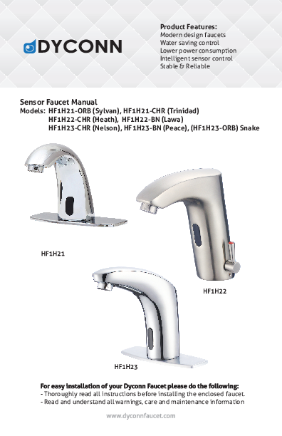
Product Features: Modern design faucets Water saving control Lower power consumption Intelligent sensor control Stable & Reliable Sensor Faucet Manual Models: HF1H21-ORB (Sylvan), HF1H21-CHR (Trinidad) HF1H22-CHR (Heath), HF1H22-BN (Lawa) HF1H23-CHR (Nelson), HF1H23-BN (Peace), (HF1H23-ORB) Snake
For easy installation of your Dyconn Faucet please do the following: - Thoroughly read all instructions before installing the enclosed faucet. - Read and understand all warnings, care and maintenance information

Product Description & Information

OPERATION AND MAINTENANCE.
CAREFULLY READ THIS INSTRUCTION MANUAL BEFORE INSTALLING AND USING
PLEASE KEEP THIS INSTRUCTION MANUAL FOR FUTURE REFERENCE FOR PRODUCT
Do not place or install the product directly under the sun or long exposure of sunlight
Do not place any catoptric items such as mirror to the opposite wall of the inductive window. Do not use contaminated water with the device. Do not soak the device in water, this will cause permanent damage.
Product Description & Information
Features: Water saving control - sensor responds to object approach in 0.5s and stops once object leave sensor range. Sanitation - automatic sensor keeps hand free of touching faucet Intelligent sensor - Faucet will automatically stop if water flows over 1 minute. Sensor resets in 10s. Faucet stops working if water supply or power is out to minimize water leakage. Low power consumption - 4 AA batteries can be consumed for 2 years 300 cycles a day. Stable & Reliable - all facuets are manufacured under harsh moisture and humidity testing.
Specification: Power Voltage: AC110 (60Hz) and Dc (4 x AA batteries) Detection range: 12-18cm Water pressure: 0.05 - 0.6 MPa Water Temperature: 0 - 80�C

Tools you will need:

Plumber's putty

Pipe tape

Phillips Screwdriver

Pliers

Adjustable Wrench

Product Diagram and Parts
Single inlet faucet Models:
Hot & cold inlet faucet Models:

Product Diagram and Parts
Single inlet faucet Models:

1. Sensor faucet body 2. Braided hose 3. Self-tapping screw 4. Plastic sleeve

5. Rubber gasket 6. Stainless steel gasket 7. Nut 8. Control box

Battery installation 1. When the battery is out, the light sensor will flash in every 2 to 3 sec. 2. Replace the battery by taking off the cover and replace new battery.
*** Main control unit can be powered by AC or battery alone.

Control Box
Single inlet control box

Single inlet control box
Clean filter : 1. Disconnect the power plug. 2. Turn off waterway. 3. Take out filter screen with
a plier. 4. Clean filter screen gently with
running water and replace the screen. Connect the power.

Terminal port

Power plugs

outlet

*** Hot/cold water mixing valve can be purchased.

in-flow

Sensor control box

hot supply

BDM Variation (Below Deck Mechnical)
Mixing Valve
cold supply

Sensor control box
Connection of Electric
*Hot & Cold hoses connect directly to water supply.

Power plugs

Installation - Single inlet faucet
Single inlet faucet
1. Connect with water inlet hose.
2. Put the hoses into basin sink hole
3. Fix the sensor faucet body with filler pieces and nut.
4. Hang the control box on the wall fixture a. Drill two wall holes, and insert the plastic expansion sleeve and screws.

5. Connect faucet hose to outlet part on control box. Connect inlet port on control box to pretempered water supply. Connect faucet sensor power cord to control box. Make sure everything is secured then connect control box power cord to power outlet.
6. ***Optional: hot/cold water mixing valve can be purchased. See control box figure (pg.4) . Please test the water temperature before installation, hot water may cause serious burn.

Installation - Hot & Cold faucet
Hot & cold inlet faucet Models:
1
1. Connect with water inlet hose.
2. Put the hoses into basin sink hole.
3. Fix the sensor faucet body with filler pieces and nut.

4. Connect the hot and cold flexible hoses to water supply valves.

4
4a. Connect electric wire A-B ; C-D

4a

Hang the batteries box on the

fixed nut. Make sure everything is

secured then connect control box

power cord to power outlet.

5. Do not connect wires A-D directly.
5

Sensor Adjustment & Troubleshooting
Sensor Adjustment 1. Turn off the water circuit and remove the faucet from the counter sink . 2. Use a clamp pliers to pick off the sponge which is at the back of the
sensor display. 3. Take the controller out, along the potentiometer and adjust lightly.
Turning clockwise will increase the inductive distance, turning anti-clockwise will decrease the inductive distance.
Troubleshooting