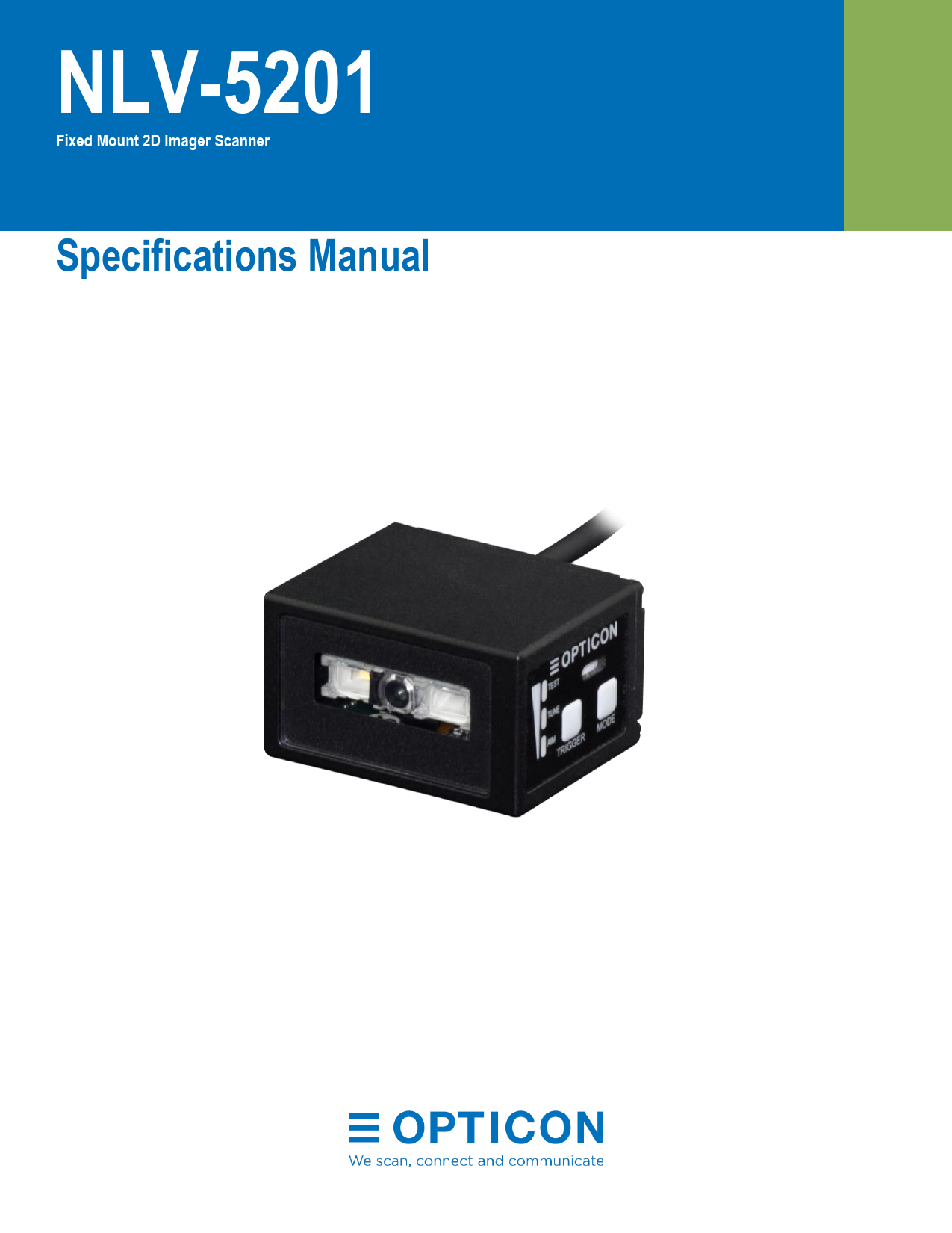
Warranty. Unless otherwise agreed in a written contract, all Opticon products are warrantied against defects in materials and workmanship for two years ...
NLV-5201 Specifications Manual iii Revision History Product Name: NLV-5201 Specification Number: SS17137 (Original Specification Number: SS17136)
NLV-5201 Fixed Mount 2D Imager Scanner Specifications Manual NLV-5201 Specifications Manual The information in this document is subject to change without notice. © 2020 Opticon. All rights reserved. This manual may not, in whole or in part, be copied, photocopied, reproduced, translated, or converted to any electronic or machine-readable form without prior written consent from Opticon. Limited Warranty and Disclaimers Please read this manual carefully before installing or using the product. Serial Number A serial number appears on all Opticon products. This official registration number is directly related to the device purchased. Do not remove the serial number from your Opticon device. Removing the serial number voids the warranty. Warranty Unless otherwise agreed in a written contract, all Opticon products are warrantied against defects in materials and workmanship for two years after purchase excluding batteries. Opticon will repair or, at its option, replace products that are defective in materials or workmanship subject to proper use of the Opticon product during the warranty period. Opticon is not liable for damages caused by modifications made by a customer. In such cases, standard repair charges may apply. If a product is returned under warranty and no defect is found, standard repair charges will apply. Opticon assumes no liability for any direct, indirect, consequential, or incidental damages arising out of use or inability to use both the hardware and software, even if Opticon has been informed about the possibility of such damages. Root cause analysis report services to troubleshoot defects or application issues are not covered under this limited warranty. Packaging The packing materials are recyclable. Damage caused by improper packaging during shipment is not covered by the warranty. Trademarks Trademarks used are the property of their respective owners. Opticon Inc. and Opticon Sensors Europe B.V. are wholly owned subsidiaries of OPTOELECTRONICS Co., Ltd., 12-17, Tsukagoshi 4-chome, Warabi-shi, Saitama, Japan 3350002. TEL +81-(0) 48-446-1183; FAX +81-(0) 48-446-1184 Support USA Phone: 800-636-0090 Email: support@opticonusa.com Web: www.opticonusa.com Europe Phone: +31235692728 Email: support@opticon.com Web: www.opticon.com ii NLV-5201 Specifications Manual Revision History Product Name: NLV-5201 Specification Number: SS17137 (Original Specification Number: SS17136) Edition Date 2nd May 22, 2020 Page - 1st September 17, 2018 - Section - - Description of Changes Applied new template. Rewrote text for clarity. Initial release. iii NLV-5201 Specifications Manual iv NLV-5201 Specifications Manual Contents 1 Overview ............................................................................................................................ 1 2 About the NLV-5201 2D Imager Scanner ........................................................................... 1 2.1 Model Details.............................................................................................................. 1 2.2 Standard Product Description ..................................................................................... 2 3 Physical Features............................................................................................................... 2 4 Detailed View ..................................................................................................................... 3 5 Basic Operation Mode ........................................................................................................ 4 5.1 Exposure Control........................................................................................................ 5 5.1.1 Automatic Adjustment Exposure Control................................................................. 5 5.1.2 Tuning Exposure Control ........................................................................................ 5 5.2 Operation Modes and Status ...................................................................................... 6 5.3 Control Panel Operation Specifications ...................................................................... 7 5.4 LED Indicator Specifications ....................................................................................... 8 6 Electrical Specifications...................................................................................................... 9 7 Power Specifications .......................................................................................................... 9 8 Interface Specification .......................................................................................................10 8.1 RS-232C Interface .....................................................................................................10 8.1.1 Initial RS-232C Communication Settings ...............................................................10 8.1.2 Interface Signals ....................................................................................................10 8.1.3 Signal Level ...........................................................................................................11 8.1.4 RS-232C Interface Circuit ......................................................................................11 8.1.5 RS-232C Interface Cable .......................................................................................12 8.2 USB Interface ............................................................................................................12 8.2.1 USB Interface Specifications..................................................................................13 8.2.2 USB Connector......................................................................................................13 8.2.3 USB Interface Circuit .............................................................................................13 8.2.4 USB Interface Cable ..............................................................................................14 9 Optical Specifications ........................................................................................................14 9.1 Basic Optical Specifications.......................................................................................14 9.2 Aiming Pattern ...........................................................................................................15 9.3 Image Range .............................................................................................................15 v NLV-5201 Specifications Manual 10 Technical Specifications ....................................................................................................15 10.1 Barcode Test Labels..................................................................................................17 10.1.1 1D Barcode Test Labels.....................................................................................17 10.1.2 GS1 DataBar/Composite....................................................................................17 10.1.3 2D Barcode Test Labels.....................................................................................17 10.2 Scan Area and Depth of Field ....................................................................................18 10.3 Printed Contrast Signal (PCS) ...................................................................................23 10.4 Minimum Resolution ..................................................................................................24 10.5 Barcode Width ...........................................................................................................25 10.6 Pitch, Skew and Tilt ...................................................................................................26 10.7 Curvature...................................................................................................................27 10.8 Motion Tolerance.......................................................................................................28 10.9 Scan Speed ...............................................................................................................29 10.10 Auto Trigger ...........................................................................................................30 10.11 Indicator Specifications ..........................................................................................31 10.12 Imager Specifications.............................................................................................31 11 Environmental Specifications ............................................................................................31 11.1 Temperature ..............................................................................................................31 11.2 Humidity ....................................................................................................................31 11.3 Ambient Light Immunity .............................................................................................32 11.4 Environmental Durability (IP) .....................................................................................32 11.5 Key Durability ............................................................................................................32 11.6 Cable Strength...........................................................................................................33 11.7 Cable Bending Strength.............................................................................................33 11.8 Vibration Resistance..................................................................................................33 11.8.1 Vibration Resistance of the Imager Scanner ......................................................33 11.8.2 Vibration Resistance of the Imager Scanner in Packaging .................................33 11.9 Drop Impact Resistance ............................................................................................34 11.9.1 Drop Impact Resistance of the Imager Scanner .................................................34 11.9.2 Drop Impact Resistance of the Imager Scanner in Packaging............................34 11.10 Electrostatic Discharge Immunity ...........................................................................34 11.11 Radio Frequency Electromagnetic Field Amplitude Modulation..............................35 11.12 Power Frequency Magnetic Field...........................................................................35 vi NLV-5201 Specifications Manual 12 Regulatory Compliance .....................................................................................................35 12.1 LED Safety ................................................................................................................35 12.2 EMC ..........................................................................................................................35 13 RoHS ................................................................................................................................36 14 Reliability...........................................................................................................................36 15 Precautions .......................................................................................................................36 16 Cleaning NLV-5201 ...........................................................................................................37 17 Product Labels ..................................................................................................................38 17.1 Serial Number Label ..................................................................................................38 17.2 Address Label............................................................................................................38 18 Packaging Specifications...................................................................................................39 18.1 Individual Packaging Specification.............................................................................39 18.2 Collective Packaging Specification ............................................................................40 19 Mechanical Drawing ..........................................................................................................41 20 Default Factory Settings ....................................................................................................42 20.1 Barcode Default Settings ...........................................................................................42 20.1.1 1D Barcode Default Settings ..............................................................................42 20.1.2 Postal Code Default Settings .............................................................................43 20.1.3 GS1 DataBar Default Settings............................................................................43 20.1.4 Composite GS1 Default Settings........................................................................44 20.1.5 2D Barcode Default Settings ..............................................................................45 20.1.6 OCR Font Default Settings.................................................................................45 20.2 Read, Trigger, and Buzzer Default Settings ...............................................................46 20.3 Interface Communication Default Settings .................................................................46 20.3.1 RS-232C Default Settings ..................................................................................46 20.3.2 USB Default Settings .........................................................................................46 vii NLV-5201 Specifications Manual Table of Figures Figure 1: Detailed View of NLV-5201............................................................................................................ 3 Figure 2: Automatic Adjustment Exposure Control ....................................................................................... 5 Figure 3: Tuning Exposure Control ............................................................................................................... 5 Figure 4: Electrical Configuration Diagram ................................................................................................... 9 Figure 5: Interface Circuit (RS-232C) ......................................................................................................... 11 Figure 6: RS-232C Loose End Interface Cable .......................................................................................... 12 Figure 7: USB Plug (A) Pin Assignment ..................................................................................................... 13 Figure 8: Interface Circuit (USB) ................................................................................................................. 13 Figure 9: USB Interface Cable .................................................................................................................... 14 Figure 10: Aiming Pattern and Image Range.............................................................................................. 15 Figure 11: Test Condition for Depth of Field ............................................................................................... 16 Figure 12: Scan Area and Depth of Field.................................................................................................... 18 Figure 13: Barcode Width ........................................................................................................................... 25 Figure 14: Pitch, Skew, and Tilt .................................................................................................................. 26 Figure 15: Curvature ................................................................................................................................... 27 Figure 16: Motion Tolerance ....................................................................................................................... 28 Figure 17: Scan Speed ............................................................................................................................... 29 Figure 18: Auto Trigger ............................................................................................................................... 30 Figure 19: Ambient Light Immunity ............................................................................................................. 32 Figure 20: Key Durability ............................................................................................................................. 32 Figure 21: Cable Bending Strength............................................................................................................. 33 Figure 22: Drop Impact Strength................................................................................................................. 34 Figure 23: Cleaning NLV-5201 ................................................................................................................... 37 Figure 24: Serial Number Label .................................................................................................................. 38 Figure 25: Serial Number Label Affixed to the NLV-5201........................................................................... 38 Figure 26: Address Label ............................................................................................................................ 38 Figure 27: Address Label Affixed to the NLV-5201 .................................................................................... 38 Figure 28: Individual Packaging (USB) ....................................................................................................... 39 Figure 29: Collective Packaging ................................................................................................................. 40 Figure 30: Mechanical Drawing................................................................................................................... 41 viii NLV-5201 Specifications Manual 1 Overview This manual provides specifications for the NLV-5201, a fixed-mount 2D imager scanner that includes these focus ranges: · Standard range (SR) · High-density (HD) · Ultra high-density (UD) Use these specifications to smoothly integrate the NLV-5201 2D imager scanner with your product and maximize performance of the imager scanner. The NLV-5201 contains these features. Unless otherwise noted, all features apply to all models: · High-speed reading: The high-speed CMOS sensor and CPU ensure efficient scanning and fast response, even in environments with movement (vibration) and poor lighting. · Integrated Tune function: The Tune function computes settings based on the target environment, which allows for the fastest possible decodes. To enable tuning, you press the mode key and monitor the 3-color indicators. For more information, see the NLV5201 User's Manual. · Motion tolerance: Capable of accurately scanning moving barcodes. · Data Edit Programming: Capable of batch reading 1D barcodes (up to 16 barcodes), 2D barcodes, and OCR. The combined output is highly configurable using regular expressions. Also supports GS1 data conversion and code coordinate output. · Green LED aiming and Warm-White LED Illumination: A well-defined, single line of green LED light and efficient warm-white LED illumination makes it easy to aim while providing safety and long life. · RoHS compliance: The 2D imager scanner is a RoHS compliant product, as declared by Optoelectronics Co., Ltd. 2 About the NLV-5201 2D Imager Scanner Before configuring or using the NLV-5201 2D imager scanner, make sure that you are familiar with its physical details and specifications. 2.1 Model Details The 2D imager scanner model is a combination of the model name, focus, interface, cable length, and optional AC adapter. 2D Imager Scanner Model Details Model Name NLV-5201 NLV-5201 Focus SR, HD, UD SR, HD, UD Interface RS232C(LE), USB, USB-COM, RS232C(9P) RS232C (+PS optional AC adapter) 1 NLV-5201 Specifications Manual Focus Description Symbol Description None Standard Range (113 mm) -HD High-Density (63 mm) -UD Ultra High-Density (43 mm) Interface Cable Description Symbol -RS232C(LE) -USB -USB-COM -RS232C(9P) -RS232C Description RS-232C loose-end cable USB cable, USB-HID is the default interface setting USB cable, USB-COM is the default interface setting RS-232C cable, power supply input is connected to D-sub 9 pin 9 RS-232C cable, external AC adapter power supply specification is used Cable Length Description Symbol Description None 1.5 mm is the standard cable length Optional AC Adapter Description Symbol Description None AC adapter not included +PS AC adapter for the RS-232C power supply is included 2.2 Standard Product Description The standard 2D imager scanner has these configurations. Additional configurations are available by special order. For help, contact your Opticon Sales Representative. Configuration NLV-5201-RS232C(LE) NLV-5201-USB Description Standard focus, RS-232C loose-end cable Standard focus, USB-HID 3 Physical Features This section describes the physical features of the NLV-5201. Feature Dimensions Weight Housing material Description W: 41.1 mm × D: 33.0 mm × H: 24.0 mm Approximately 125 g Zinc alloy diecasting Notes Excludes the protruding part of the 2D imager scanner. Excludes the cable. 2 4 Detailed View NLV-5201 Specifications Manual 1. Scan Window 2. Mounting Holes X X X X X X 3. Control Panel 4. Buzzer Holes 5. Status LED 6. Trigger Key 7. Mode Key Figure 1: Detailed View of NLV-5201 3 NLV-5201 Specifications Manual NLV-5201 Components Callout Name 1 Scan Window 2 Mounting Holes 3 Control Panel 4 Buzzer Holes 5 Status LED 6 Trigger Key 7 Mode Key Description Light paths of the imager scanner, LED illumination, and aiming. Make sure that the lens is free from dust and dirt before scanning. For more information, see "Cleaning the NLV-5201" on page 37. Screw holes (two on the bottom and two on the side) that you can use to mount the imager scanner. 2 holes on the bottom and side. For the mounting hole dimensions, see "Mechanical Drawing" on page 41. Use the control panel to run Test mode, Tune mode, and Aim mode. You can also select the bank. For more information, see "Control Panel Operation Specifications" on page 7. Sound from a built-in buzzer comes out through these holes. When the holes are covered, the buzzer sound is diminished. The sound varies depending on the settings. You can configure the frequency, loudness, and duration of the buzzer. Indicates status with 3-color LEDs: red, orange, and green. For more information, see "LED Indicator Specifications" on page 8. The default key is the trigger key. When you select a mode from the control panel, the trigger key operates as an execution key. Use the mode key to select and cancel the mode. Press and hold the mode key to return to saved settings bank select mode. 5 Basic Operation Mode Make sure you understand the symbols used to indicate the states of the status LED indicator. Symbol Description OFF Blinking ON 4 NLV-5201 Specifications Manual 5.1 Exposure Control Exposure Control determines shutter speed and illumination parameters. Exposure Control can be set to: · Automatic Adjustment · Tuning 5.1.1 Automatic Adjustment Exposure Control By default, Exposure Control is set to Automatic Adjustment. Exposure is automatically adjusted when the reading distance and the barcode to read is not fixed. Example of use: Holding a product to read the barcode. Figure 2: Automatic Adjustment Exposure Control 5.1.2 Tuning Exposure Control When the reading distance and the barcode to read is fixed, barcode reading is optimized by setting the exposure parameters. Example of use: Product barcodes moving along a factory line. Figure 3: Tuning Exposure Control 5 NLV-5201 Specifications Manual 5.2 Operation Modes and Status Mode Mark Description Normal - When the imager scanner is in a read mode, these conditions are used to trigger barcode reading: · Command trigger by serial communication (USB-COM/RS-232C) · External trigger signal (RS-232C) · Auto trigger · Trigger key Test mode TEST Test mode is used to test the read rate. The read rate is displayed on the LED indicator every 10 successful reads. Tune mode TUNE Used to determine and set the optimum exposure. When tuning is finished, the barcode limits, exposure setting, etc. are saved to the current saved settings bank. The read rate is also displayed on the LED indicator. Saved settings bank The bank is the area to save the exposure (from 1 to 7, default = 1) adjusted in tune mode. Aim AIM mode Aim mode controls the aiming LED and indicates whether the barcode is close to the center coordinate of the image sensor to LED indicator. 6 NLV-5201 Specifications Manual 5.3 Control Panel Operation Specifications This section describes the operation of the control panel on the side of housing. Mode LED Indicator Key Trigger Key Operation Operation Description Mode Trigger Key for reading Normal Normal operation status. Press once (within 2 sec) Press twice (within 2 sec) Mode transition by pressing once Mode transition by pressing once Test Tune Press 3 times (within 2 sec) Press 4 times (within 2 sec) Press for 2 seconds or more (Press again to select) Mode transition by pressing once Mode transition by pressing once Aim Bank selection Press both keys at the same time for 5 seconds to enter "initialization standby." Press the trigger key again to initialize. Initialize Used when testing the read rate. Automatically finds the optimum exposure settings based on the current barcode reading environment. When tuning is finished, the barcode symbology type is limited, and the exposure settings are saved to the current saved settings bank. The read rate is also displayed on the LED indicator. Controls the aiming LED and indicates whether the barcode is close to the center of the image sensor view. To display the currently used saved settings bank on the LED, press and hold the mode key for more than 2 seconds. To cycle through the saved settings banks, in order, press the mode key again. To select and use the currently displayed saved settings bank, press the trigger key. To enter initialization standby, press the mode key and trigger key at the same time and hold for 5 seconds. To initialize, press the trigger key. To cancel initialization standby, press the mode key. 7 NLV-5201 Specifications Manual 5.4 LED Indicator Specifications The status LED's indicate the read result and USB communication status. In read rate mode, the reading success rate is indicated by these three 3-color LED's. Normal Mode Status LED Indication Status LED Indication Reading Success Waiting for USB Communication Communication/ Reading Error "Test mode", "Tune mode" and "Aim mode" LED Indication Test and tuning display the read rate 10 times. Read Rate Central Coordinate LED Indication 0 - 40 % Far from the center 50 - 70 % 80 - 90% 100% Close to the center "Saved Settings Bank No." LED Indication The number of the currently used saved settings bank blinks when you press the mode key for more than 2 seconds. Values (from 1 to 7) are in binary. Bank No. LED Indication No. 1 No. 2 No. 3 No. 4 No. 5 No. 6 No. 7 8 NLV-5201 Specifications Manual 6 Electrical Specifications The NLV-5201 consists of these components: · Decoder Section: Decodes 1D and 2D barcodes and OCR fonts from an image scanned by the CMOS sensor camera module. · Communication Control Section: Communicates with a host device. · SUB Board: Electrical distribution board for the main power supply conversion. The RS-232C interface model requires an external DC 5.0 V power supply. The USB interface model is powered through the USB cable, so no external power supply is needed. Imaging Lens Power Supply Circuit CMOS Image Sensor Power Supply Circuit Power Supply Circuit 3.3V5.0V RS-232C / +5V USB Host I/F (RS-232C/USB) Host Illumination Warm White LED(1) Aiming Green LED (1) Camera Section MCU Illumination Drive Circuit LED (1) CPU FPC FROM/ LPDDR2 Decoder Section Figure 4: Electrical Configuration Diagram Indicator Control Circuit FFC Status LEDx3 Trigger Key Mode Key Buzzer FPC SUB Board 7 Power Specifications Reference temperature for current consumption is 25° C. Power Specifications Specification Range of Operating Voltage Current Consumption Value 4.5 V to 5.5 V Maximum: 450 mA Reading: 265 mA (Typ.) Auto trigger standby: 190 mA (Typ.) Standby: 40 mA (Typ.) 9 NLV-5201 Specifications Manual 8 Interface Specification The NLV-5201 uses these interfaces: · RS-232C · USB (COM/HID) 8.1 RS-232C Interface This section describes RS-232C serial communications between the imager scanner and a host computer. If the host COM port is not open, the imager scanner cannot send data and will emit an error sound. Note: With the RS-232C interface, the imager scanner can transfer images. 8.1.1 RS-232C Communication Settings Base Communication Settings Setting Value Baud rate 300 to 115200 bps Data length 7 bits, 8 bits Parity bits Stop bits None, Even, Odd 1 bit, 2 bits Default 9600 bps 8 bits None 1 bit 8.1.2 Interface Signals Signal names are based on signals transmitted from the imager scanner to the host. Interface Signals Name VCC Trigger OK NG S-GND RTS CTS TxD RxD Shield GND Cable Color Red Brown Yellow Orange Black Gray Blue Green White (Black) Notes Power-supply voltage 4.5 V to 5.5 V (Typ. 5 V) External trigger input terminal External OK output terminal External NG output terminal Heat shrink tube 10 NLV-5201 Specifications Manual 8.1.3 Signal Level Signal names are based on signals transmitted from the imager scanner to the host. Signal Levels Name TxD RxD RTS CTS IN/Out OUT IN OUT IN Mark -5 to -15 -3 to -15 -5 to -15 -3 to -15 Voltage (V) Space +5 to +15 +3 to +15 +5 to +15 +3 to +15 Signal Level Sequencer Signal (Loose End, Only) Name IN/Out L Level Trigger IN -0.3 V - 0.6 V OK OUT 0.3 V/10 mA NG OUT 0.3 V/10 mA Trigger IN -0.3 V - 0.6 V Voltage (V) Space/ON 3 V - Vcc+0.3 V Vcc Vcc 3 V - Vcc+0.3 V 8.1.4 RS-232C Interface Circuit NLV-5201 VCC TxD RxD RTS CTS OK / NG Barcode reader main circuit Trigger S-GND F-GND External device DC 5V + + RxD TxD CTS RTS Load MAX DC 24V Figure 5: Interface Circuit (RS-232C) 11 NLV-5201 Specifications Manual 8.1.5 RS-232C Interface Cable RS-232C Interface Cable Specifications Parameter Specification Cable length 1500 mm Exposed wire length 70 mm Wire conductor diameter AWG28 Insulator outer diameter 0.58 mm Exposed conductor length 7 mm Cable diameter 3.8 mm Weight Approx. 45 g Cable material PVC 3.8 1500±50 7±2 60±5 Figure 6: RS-232C Loose End Interface Cable [Unit: mm] 8.2 USB Interface The NLV-5201 can use either USB interface: · Human Interface Device Class (HID) · Communication Device Class (COM) The COM interface allows bidirectional serial communication, which supports transmitting commands from the host computer to the imager scanner, as well as receiving barcode data. To use USB-COM, you need to install the latest version of the Opticon USB-COM driver on your host device. If the host COM post is not open, the imager scanner cannot send data and will emit an error sound. Note: With the USB-COM interface, the imager scanner can transfer images. 12 NLV-5201 Specifications Manual 8.2.1 USB Interface Specifications The USB interface model is bus powered. No external power supply is needed. Caution: If you are using USB-HID to transmit barcode data, using the host keyboard may cause data to be lost. USB-COM Interface Specifications Setting Bus-power class Speed Interface Transfer Speed Vendor ID Product ID (HID) Product ID (COM) Description Use only a high-power (500 mA) USB port. Full Speed (12 Mbps) HID/COM (Virtual COM Port) USB2.0 Full Speed 065A A001 A002 8.2.2 USB Connector Pin No. Name 1 VCC 2 -DATA 3 +DATA 4 GND Figure 7: USB Plug (A) Pin Assignment 8.2.3 USB Interface Circuit +3.3V Full Speed USB Transceiver Buffers Figure 8: Interface Circuit (USB) 1 2 Front View 3 4 USB A Connector Pin No. Signal VBUS 2 -D 3 +D 4 GND Shell FG 13 NLV-5201 Specifications Manual 8.2.4 USB Interface Cable USB Interface Cable Specifications Parameter Specification Cable length 1500 mm Cable diameter 3.8 mm Weight Approx. 70 g Cable material PVC 3.8 #1 #4 1500±50 Figure 9: USB Interface Cable [Unit: mm] 9 Optical Specifications 9.1 Basic Optical Specifications Parameter Description Scanning method Monochrome CMOS area sensor Number of effective pixels (Column) × (Row) Image capture speed (fastest speed at which an image is captured) Frame rate Sensor shutter speed Minimum shutter speed Focal distance Distance from the front edge of the imager scanner View angle Reading light source (LED × 1) Aiming light source (LED × 1) Scan window Horizontal Vertical Diagonal White LED Color Green LED Wavelength Material Specification N/A 640 × 480 dots (0.30 million pixels) 100 fps 30s 113 mm (SR models) 63 mm (HD models) 43 mm (UD models) Approx. 38.0° Approx. 28.9° Approx. 46.4° Warm white 2600 - 3700 K Single line 525 nm PMMA 14 NLV-5201 Specifications Manual 9.2 Aiming Pattern Aiming indicates the appropriate reading distance by projecting a bar of green LED light: · The optical axis of the imaging field of view and the center of the horizontal aiming bar coincide at a distance of L=148±20 mm from the front edge of the imager scanner. · The width of the aiming bar at a distance of L=148 mm is 90%±10% of the width of the horizontal field of view. · The sharpest aiming bar distance is 113 ± 10 mm (SR models), 63 ± 10 mm (HD models), or 43 ± 10 mm (UD models). Horizontal FOV Distance: L Aiming Width Vertical FOV Figure 10: Aiming Pattern and Image Range 9.3 Image Range The image range is the imaging field of view (not the scan area). Image Range for SR Models L: Distance from the Front Edge of the Imager Scanner (mm) 80 100 120 140 160 180 Horizontal Field of View (FOV) 57.1 70.9 98.5 98.5 112.3 126.0 Vertical Field of View (FOV) Note: The range is ±5% from these values. 42.7 53.0 63.3 73.6 83.9 94.2 Image Range for HD Models L: Distance from the Front Edge of the Imager Scanner (mm) 40 60 80 100 120 140 Horizontal Field of View (FOV) 29.6 43.4 57.1 70.9 98.5 98.5 Vertical Field of View (FOV) 22.1 32.4 42.7 53.0 63.3 73.6 Note: The range is ±5% from these values. 15 NLV-5201 Specifications Manual Image Range for UD Models L: Distance from the Front Edge of the Imager Scanner (mm) 30 40 50 60 80 100 Horizontal Field of View (FOV) Vertical Field of View (FOV) Note: The range is ±5% from these values. 22.7 29.6 36.5 43.4 57.1 70.9 17.0 22.1 27.3 32.4 42.7 53.0 10 Technical Specifications The conditions for technical specifications are as follows, unless otherwise specified in each section. Technical Specification Conditions Specification Condition Ambient Temperature and Humidity Room temperature and room humidity Ambient Light 100 to 500 lux Pitch Angle = 0° Skew Angle = 15° Tilt Angle = 0° Code Position Near the center of the image Curvature R = Power Supply Voltage 5.0 V PCS (1D and 2D) 0.9 or higher Scanning Test Accept the performance with 90% or more success rate for 10 scan attempts. One reading should be 2 seconds. Barcode Test Sample (1D and 2D) Specified in "Barcode Test Labels" on page 17. Note: For 1D barcodes, use OPTOELECTRONICS test samples. For GS1 DataBar, stacked barcodes, and 2D barcodes, use barcodes from a dedicated barcode printer. Near center of the image 15° Figure 11: Test Condition for Depth of Field 16 NLV-5201 Specifications Manual 10.1 Barcode Test Labels This section describes the barcode labels used when the depth of field was measured. 10.1.1 1D Barcode Test Labels Code 39 Resolution PCS (MRD) 0.10 mm (3.9 mil) 0.9 (80) 0.127 mm (5 mil) 0.20 mm (7.9 mil) 0.254 mm (10 mil) 0.508 mm (20 mil) Size (mm) 26 × 10 11 × 10 100 × 10 32.5 × 12 36 × 25 No. of Digits 16 4 31 7 4 Code 128 Resolution 0.20 mm (7.9 mil) PCS (MRD) 0.9 (80) Size (mm) 42 × 10 No. of Digits 16 UPC/EAN Resolution 0.33 mm (13 mil) PCS (MRD) 0.9/0.3 (80/23) Size (mm) 31.5 × 25.0 No. of Digits 12/13 10.1.2 GS1 DataBar/Composite GS1-DataBar Limited Resolution 0.169 mm (6.7 mil) 0.169 mm (6.7 mil) Symbology Limited Limited-Composite PCS (MRD) 0.9 (80) Size (mm) 12 × 1.5 12 × 3.0 No. of Digits 14 26 10.1.3 2D Barcode Test Labels PDF417 Resolution Error Correction 0.169 mm (6.7 mil) Level-3 0.254 mm (10 mil) PCS (MRD) 0.9 (80) Size (mm) 23 x 10 35 x 15 QR Code: Model-2 Resolution 0.169 mm (6.7 mil) 0.381 mm (15 mil) Error Correction M PCS (MRD) 0.9 (80) Size (mm) 5 x 5 11 x 11 Data Matrix Resolution Error Correction PCS (MRD) Size (mm) 0.169 mm (6.7 mil) ECC200 0.9 (80) 4 x 4 0.254 mm (10 mil) 6 x 6 Note: Size is measured using the outline dimensions excluding the quiet zone. No. of Characters 58 No. of Characters 44 No. of Characters 40 17 NLV-5201 Specifications Manual 10.2 Scan Area and Depth of Field The scan area is measured from the front edge of the imager scanner. The depth of field depends on the view angle and symbol length. Depth of field values provided are the typical values measured by tilting the test chart 15° from the optical axis. The focal point of the camera, and therefore the depth of field, is different for the SR, HD, and UD models. This section describes the depths of field for all three models. 10.2.1 Scan Area and Depth of Field for SR Models 100 75 50 25 0 25 50 75 100 0 50 100 150 200 250 300 Code 39 Code 128 0.127mm (5mil) 53 126 52 69 62 0.254mm (10mil) 0.508mm (20mil) 0.20mm (7.9mil) 191 237 [Unit: mm] 433 EAN/UPC 50 0.33mm (13mil) 291 PDF417 0.169mm (6.7mil) 49 146 0.254mm (10mil) 42 QR Code 0.169mm (6.7mil) 60 111 22 0.381mm (15mil) Data Matrix 0.169mm (6.7mil) 62 116 0.254mm (10mil) 43 173 Figure 12: Scan Area and Depth of Field for SR Models 211 250 18 NLV-5201 Specifications Manual Depth of Field for SR Models Resolution Symbology PCS Type (MRD) Guaranteed Value Near Far TA = 25°C Typical Value Near Far 0.127 mm (5 mil) Code 39 0.9 (0.8) 64 mm (2.5) 110 mm (4.3) 53 mm (2.1) 126 mm (5.0) 0.254 mm (10 mil) Code 39 0.9 (0.8) 62 mm (2.4) 209 mm (8.2) 52 mm (2.0) 237 mm (9.3) 0.508 mm (20 mil) Code 39 0.9 (0.8) 84 mm (3.3) 371 mm (14.6) 69 mm (2.7) 433 mm (17.0) 0.20 mm (7.9 mil) Code 128 0.9 (0.8) 77 mm (3.0) 165 mm (6.5) 62 mm (2.5) 191 mm (7.5) 0.33 mm (13 mil) UPC/EAN 0.9 (0.8) 62 mm (2.4) 248 mm (9.8) 50 mm (2.0) 291 mm (11.5) 0.169 mm (6.7 mil) QR Code 0.9 (0.8) 73 mm (2.9) 97 mm (3.8) 60 mm (2.4) 111 mm (4.4) 0.381 mm (15 mil) QR Code 0.9 (0.8) 27 mm (1.1) 214 mm (8.4) 22 mm (0.9) 250 mm (9.8) 0.169 mm (6.7 mil) Data Matrix 0.9 (0.8) 75 mm (3.0) 101 mm (4.0) 62 mm (2.4) 116 mm (4.6) 0.254 mm Data Matrix 0.9 (0.8) 55 mm 149 mm 43 mm 173 mm (10 mil) (2.2) (5.9) (1.7) (6.8) Note: The depth of field was determined using OPTOELECTRONICS test chart PCS 0.9, without specular reflection and at room temperature and room humidity. 19 NLV-5201 Specifications Manual 10.2.2 Scan Area and Depth of Field for HD Models 0 50 100 150 200 75 50 25 0 25 50 75 Code 39 Code 128 EAN/UPC 0.076mm (3mil) 45 72 0.127mm (5mil) 35 119 55 68 0.254mm (10mil) 0.20mm (7.9mil) 0.33mm (13mil) 48 179 159 200 PDF417 QR Code 0.127mm (5mil) 39 109 0.254mm (10mil) 46 0.127mm (5mil) 43 91 0.381mm (15mil) 24 154 182 0.127mm (5.0mil) 48 78 Data Matrix 0.254mm (10mil) 28 139 Figure 13: Scan Area and Depth of Field for HD Models [Unit: mm] 20 NLV-5201 Specifications Manual Depth of Field for HD Models Resolution Symbology PCS Type (MRD) Guaranteed Value Near Far TA = 25°C Typical Value Near Far 0.127 mm (5 mil) Code 39 0.9 (0.8) 53 mm (2.1) 63 mm (2.5) 45 mm (1.8) 72 mm (2.8) 0.254 mm (10 mil) Code 39 0.9 (0.8) 43 mm (1.7) 102 mm (4.0) 35 mm (1.4) 119 mm (4.7) .508 mm (20 mil) Code 39 0.9 (0.8) 62 mm (2.4) 155 mm (6.1) 55 mm (2.2) 179 mm (7.0) 0.2 mm (7.9 mil) Code 128 0.9 (0.8) 77 mm (3.0) 138 mm (5.4) 68 mm (2.7) 159 mm (6.3) 0.33 mm (13 mil) UPC/EAN 0.9 (0.8) 62 mm (2.4) 171 mm (6.7) 48 mm (1.9) 200 mm (7.9) 0.169 mm (6.7 mil) PDF417 0.9 (0.8) 46 mm (1.8) 95 mm (3.7) 39 mm (1.5) 109 mm (4.3) 0.254 mm (10 mil) PDF417 0.9 (0.8) 51 mm (2.0) 135 mm (5.3) 46 mm (1.8) 154 mm (6.1) 0.169 mm (6.7 mil) QR Code 0.9 (0.8) 49 mm (1.9) 79 mm (3.1) 43 mm (1.7) 91 mm (3.6) 0.381 mm (15 mil) QR Code 0.9 (0.8) 31 mm (1.2) 153 mm (6.0) 24 mm (0.9) 180 mm (7.1) 0.169 mm (6.7 mil) Data Matrix 0.9 (0.8) 55 mm (2.2) 63 mm (2.5) 48 mm (1.9) 78 mm (3.1) 0.254 mm Data Matrix 0.9 (0.8) 35 mm 120 mm 28 mm 139 mm (10 mil) (1.4) (4.7) (1.1) (5.5) Note: The depth of field was determined using OPTOELECTRONICS test chart PCS 0.9, without specular reflection and at room temperature and room humidity. 21 NLV-5201 Specifications Manual 10.2.3 Scan Area and Depth of Field for UD Models 0 25 50 75 100 125 50 25 0 25 Code 39 EAN/UPC QR Code 0.076mm (3mil) 28 65 50 [mm] 0.127mm (5mil) 23 82 53 50 0.254 (10mil) 108 0.33mm (13mil) 120 0.084mm (3.3mil) 33 55 0.381mm (15mil) 22 109 Data Matrix 0.084mm (3.3mil) 35 55 0.254mm (10mil) 22 Figure 14: Scan Area and Depth of Field for UD Models 86 [Unit: mm] 22 NLV-5201 Specifications Manual Depth of Field for UD Models Resolution Symbology PCS Type (MRD) Guaranteed Value Near Far TA = 25°C Typical Value Near Far 0.076 mm (3 mil) Code 39 0.9 (0.8) 35 mm (1.4) 56 mm (2.2) 28 mm (1.1) 65 mm (2.6) 0.127 mm (5 mil) Code 39 0.9 (0.8) 35 mm (1.4) 68 mm (2.7) 23 mm (0.9) 82 mm (3.2) 0.254 mm (10 mil) Code 39 0.9 (0.8) 64 mm (2.5) 93 mm (3.7) 53 mm (2.1) 108 mm (4.3) 0.33 mm (13 mil) UPC/EAN 0.9 (0.8) 66 mm (2.6) 102 mm (4.0) 50 mm (2.0) 120 mm (4.7) 0.084 mm (3.3 mil) QR Code 0.9 (0.8) 42 mm (1.7) 45 mm (1.8) 33 mm (1.3) 55 mm (2.2) 0.381 mm (15 mil) QR Code 0.9 (0.8) 29 mm (1.1) 92 mm (3.6) 22 mm (0.87) 109 mm (4.3) 0.084 mm (3.3 mil) Data Matrix 0.9 (0.8) 43 mm (1.7) 48 mm (1.9) 35 mm (1.4) 55 mm (2.2) 0.254 mm Data Matrix 0.9 (0.8) 33 mm 72 mm 22 mm 86 mm (10 mil) (1.3) (2.8) (0.87) (3.4) Note: The depth of field was determined using OPTOELECTRONICS test chart PCS 0.9, without specular reflection and at room temperature and room humidity. 10.3 Printed Contrast Signal (PCS) PCS: 0.3 or higher PCS Conditions Condition MRD Barcode Sample Description 23% ( 80% reflectivity of space and quiet zone) UPC specified in "Barcode Test Labels" on page 17. (Resolution: 0.33 mm, PCS: 0.3) MRD = Minimum reflectance of white space - Maximum reflectance of black bar Reflectance of white space - Reflectance of black bar PCS = Reflectance of white space Note: Make sure that the optical window is clean and free from scratches. A dirty or damaged optical window may decrease reading performance. 23 NLV-5201 Specifications Manual 10.4 Minimum Resolution 10.4.1 Minimum Resolution for SR Models For details, see "Barcode Test Labels" on page 17. Minimum Resolution Barcodes Barcode Type Barcode Symbology 1D Barcode Code 39 GS1 DataBar GS1 DataBar Limited Stacked Barcode PDF417, GS1 DataBar Limited Composite 2D Barcode QR Code, Data Matrix Minimum Resolution 0.1 mm 0.169 mm 0.169 mm 0.169 mm Minimum Resolution Conditions Condition Description Distance 83 mm from the front edge of the imager scanner Angle = 0°, =+15°, = 0° Curvature R = 10.4.2 Minimum Resolution for HD Models For details, see "Barcode Test Labels" on page 17. Minimum Resolution Barcodes Barcode Type Barcode Symbology 1D Barcode Code 39 GS1 DataBar GS1 DataBar Limited Stacked Barcode PDF417, GS1 DataBar Limited Composite 2D Barcode QR Code, Data Matrix Minimum Resolution 0.076 mm 0.127 mm 0.127 mm 0.127 mm Minimum Resolution Conditions Condition Description Distance 58 mm from the front edge of the imager scanner Angle = 0°, =+15°, = 0° Curvature R = 10.4.3 Minimum Resolution for UD Models For details, see "Barcode Test Labels" on page 17. Minimum Resolution Barcodes Barcode Type Barcode Symbology 1D Barcode Code 39 2D Barcode QR Code, Data Matrix Minimum Resolution 0.051 mm 0.084 mm 24 NLV-5201 Specifications Manual Minimum Resolution Conditions Condition Description Distance 43 mm from the front edge of the imager scanner Angle = 0°, =+15°, = 0° Curvature R = 10.5 Barcode Width Barcode width: 100 mm Barcode Width Conditions Condition Description Barcode Sample Code 39, 0.20 mm/PCS 0.9. For details, see "Barcode Test Labels" on page 17. Distance 168 mm from the front edge of the imager scanner (SR models) 138 mm from the front edge of the imager scanner (HD models) 73 mm from the front edge of the imager scanner (UD models) Angle = 0°, =+15°, = 0° Curvature R = Figure 15: Barcode Width 25 NLV-5201 Specifications Manual 10.6 Pitch, Skew, and Tilt Pitch, Skew, and Tilt Orientation Description Pitch = ±65° (SR models) = ±60° (HD models) = ±50° (UD models) Skew = ±65° (SR and HD models) = ±50° (UD models) Tilt = 360° Pitch, Skew, and Tilt Conditions Condition Description Barcode Sample Code 39, 0.508 mm. For details, see "Barcode Test Labels" on page 17. Distance 128 mm from the front edge of the imager scanner (SR models) 98 mm from the front edge of the imager scanner (HD models) 48 mm from the front edge of the imager scanner (UD models) Curvature R = Angle Pitch: = +15°, = 0° Skew, Dead Zone: = 0°, = 0° Tilt: = 0°, = +15° - -+ + + - Figure 16: Pitch, Skew, and Tilt 26 NLV-5201 Specifications Manual 10.7 Curvature 0.33 mm 12-digit UPC R 20 mm (SR and HD models) R 25 mm (UD models) Note: Decoding may fail due to specular reflection. Curvature Conditions Condition Barcode Sample Distance Angle Description UPC, 0.33 mm. For details, see "Barcode Test Labels" on page 17. 113 mm from the front edge of the imager scanner (SR models) 98 mm from the front edge of the imager scanner (HD models) 78 mm from the front edge of the imager scanner (UD models) = 0°, =+15°, = 0° R Figure 17: Curvature 27 NLV-5201 Specifications Manual 10.8 Motion Tolerance 2.54 m/s (UPC 100%) (SR models) 1.0 m/s (QR Code) (HD models) Motion Tolerance Conditions Condition Description Ambient Temperature and Humidity Room temperature and room humidity Ambient Light 500 lux to 1000 lux (on the surface of the barcode) Distance 128 mm from the front edge of the imager scanner (SR models) 118 mm from the front edge of the imager scanner (HD models) PCS (1D and 2D) 0.9 or higher Barcode Sample 0.33 mm UPC (SR models) 0.381 mm QR Code (HD models) For details, see "Barcode Test Labels" on page 17. Note: Successful reading at the indicated speed cannot be guaranteed. If the surface is highly reflective, the illumination LED may be reflected and cause scanning to fail. Figure 18: Motion Tolerance 28 NLV-5201 Specifications Manual 10.9 Scan Speed Scan speed only applies to SR and HD models. Number of scans per second: · 1D Barcode: 40 scans/sec. · 2D Barcode: 25 scans/sec. Scan Speed Conditions Condition Description Ambient Temperature and Humidity Room temperature and Room humidity Ambient Light 500 lux to 1000 lux (on the surface of a barcode) Distance 113 mm from the front edge of the imager scanner engine (SR models) 98 mm from the front edge of the imager scanner engine (HD models) Scan Mode Continuous scan Angle = 0°, =+15°, = 0° Curvature R = Code Position Center of the image PCS (1D and 2D) 0.9 or higher 1D Barcode 0.33 mm UPC/EAN. For details, see "Barcode Test Labels" on page 17. 2D Barcode 0.254 mm Data Matrix. For details, see "Barcode Test Labels" on page 17. Note: Performance is not guaranteed in other conditions. Center of the image Figure 19: Scan Speed 29 NLV-5201 Specifications Manual 10.10 Auto Trigger In auto trigger mode, the imager scanner detects an abrupt change in brightness in the scan area and automatically starts scanning. Auto trigger is activated when a black sheet of paper is placed in front of a gray sheet of paper. You can configure auto trigger. Auto Trigger Conditions Condition Paper Ambient light Moving speed of detected paper Ambient temperature and humidity Description Black paper: Black 010010016, from Glory paper company Gray paper: Silver-gray 010010016, from Glory paper company 500 lux to 1000 lux (on the surface of a barcode) Less than 2 m/s Room temperature and room humidity Background Paper Figure 20: Auto Trigger 30 NLV-5201 Specifications Manual 10.11 Indicator Specifications Indicator Description Status LED Upper panel, 3 color LED: red, orange, and green Buzzer Adjustable volume and tone 10.12 Imager Specifications Specification Description Image data format Windows Bitmap, JPEG Shades of gray 1024, 256, 16, 2 Range of output image Select top/bottom (column) and left/right (row) Resolution of output image Full, 1/2, 1/4 Interface of output image RS-232C, USB-COM Baud rate (full resolution) USB-COM, full speed (approx. 3 sec.) RS-232C, 115200 kbps (approx. 40 sec.) 11 Environmental Specifications Unless otherwise noted, these conditions apply to all environmental specifications where applicable. Environmental Specification Conditions Condition Description Barcode Sample 0.33 mm UPC specified in "Barcode Test Labels" on page 17. Distance 128 mm from the front edge of the imager scanner (SR models) 118 mm from the front edge of the imager scanner (HD models) 78 mm from the front edge of the imager scanner (UD models) Angle = 0°, =+15°, = 0° Curvature R = Scanning Test Read at intervals of 300 ms Power Supply Voltage 5.0 V 11.1 Temperature Operating Temperature: 0 to 50 °C Storage Temperature: -20 to 60 °C 11.2 Humidity Operating Humidity Storage Humidity 20 to 85%RH (no condensation, no frost) 20 to 90%RH (no condensation, no frost) 31 NLV-5201 Specifications Manual 11.3 Ambient Light Immunity Scanning performance is optimal when the illumination on the surface of a barcode is between zero and these values: Incandescent Light: Fluorescent Light: Sunlight: 10,000 lux 10,000 lux 100,000 lux Note: To achieve the best scanning performance, make sure that direct ambient light and specular reflection do not enter the light receiving section of the imager scanner. Illuminance measuring surface 15° Figure 21: Ambient Light Immunity 11.4 Environmental Durability (IP) IEC IP65 equivalent 11.5 Scanner Key Durability The imager scanner key is designed to withstand the conditions of the following key durability test. Key Durability Test: Position the imager scanner as shown in the next illustration. Use a push rod with a 10 mm diameter to press and release the key with a force of 9.8 N (1 kgf). Press and release the key 50,000 times. Figure 22: Scan Key Durability Test 32 NLV-5201 Specifications Manual 11.6 Cable Strength The cable is designed to withstand the conditions of the following cable strength test. Cable Strength Test: Attach the scanner to a stationary object. Pull the cable with a force of 25 N (2.5 kgf, static loading) for 60 seconds. 11.7 Cable Bending Strength The cable is designed to withstand the conditions of the following cable bending strength test. Cable Bending Strength Test: Add a load of 4.9 N (500 gf) to the cable. Flex the cable 60° in both directions 700 times. 60° 60° Figure 23: Cable Bending Strength 11.8 Vibration Tolerance 11.8.1 Vibration Tolerance of the Imager Scanner The imager scanner is designed to withstand the conditions of the following vibration test. Vibration Test: Turn off the imager scanner. Increase the frequency of the vibration from 10 Hz to 100 Hz at a maximum acceleration of 19.6 m/s2 (2.0 g) for 30 minutes. Repeat the process 2 times in the X-direction, Y-direction, and Z-direction. 11.8.2 Vibration Tolerance of the Imager Scanner in Packaging The individually packaged imager scanner is designed to withstand the conditions of the following vibration test. Vibration Test: Make sure the imager scanner is individually packaged. Increase the frequency of the vibration from 10 Hz to 100 Hz at a maximum acceleration of 19.6 m/s2 (2.0 g) for 30 minutes. Repeat the process 2 times in the X-direction, Y-direction, and Z-direction. 33 NLV-5201 Specifications Manual 11.9 Drop Impact Tolerance 11.9.1 Drop Impact Tolerance of the Imager Scanner The imager scanner is designed to withstand the conditions of the following drop test. Drop test: Drop the imager scanner a total of 15 times (3 times for each position shown in the next illustration) from a height of 75 cm onto a concrete floor. 75cm Concrete floor Figure 24: Drop Impact Resistance 11.9.2 Drop Impact Tolerance of the Imager Scanner in Packaging The individually packaged imager scanner is designed to withstand the conditions of the following drop test. Drop test: Drop an individually packaged imager scanner a total of 10 times (on any 1 corner, 3 edges, and 6 faces) from a height of 100 cm onto a concrete floor. 11.10 Electrostatic Discharge Immunity The Electrostatic Discharge Immunity Test method is compliant with IEC-61000-4-2. (150 pf, 330 ohm). The imager scanner meets the electromagnetic immunity requirements for electronic equipment and can withstand these conditions: No damage: ±15 kV (air discharge, direct) No malfunction: ±8 kV (air discharge, direct) ±6 kV (contact discharge, direct / indirect) 34 NLV-5201 Specifications Manual 11.11 Radio Frequency Electromagnetic Field Amplitude Modulation The Radio Frequency Electromagnetic Field Amplitude Modulation Test is compliant with IEC61000-4-3. Radio Frequency Electromagnetic Field Amplitude Modulation Condition Frequency Level AM Description 80 to 1000 MHz 3 V/m 80% (AM) 11.12 Power Frequency Magnetic Field The Power Frequency Magnetic Field Test is compliant with IEC-61000-4-8. Power Frequency Magnetic Field Condition Frequency Level Description 50 and 60 Hz 3 A/m 12 Regulatory Compliance 12.1 LED Safety For warm white LED and green LED: IEC 62471:2006 Exempt Risk Group 12.2 EMC EN55032 EN55024 Class B FCC Part 15 Subpart B Class B This device complies with part 15 of the FCC Rules. Operation is subject to the following two conditions: ( 1 ) this device may not cause harmful Interference, and ( 2 ) this device must accept any interference received, including interference that may cause undesired operation. VCCI-CISPR 32:2016 Class B This is a Class B product, to be used in a domestic environment, based on the Technical Requirement of the Voluntary Control Council for Interference from Information Technology Equipment (VCCI). If this is used near a radio or television receiver in a domestic environment, it may cause radio interference. European Conformity: CE Marking 35 NLV-5201 Specifications Manual 13 RoHS The NLV-5201 is compliant with RoHS. RoHS Directive The restriction of the use of certain hazardous substances in electrical and electronic equipment, 2011/65/EU. 14 Reliability The imager scanner will perform reliably if it is operated under normal operating conditions in the range of advised operating temperature and humidity without excessive electrical or mechanical shock. MTBF (Mean Time Between Failures): 50,000 hours 15 Precautions Caution: Make sure you understand these precautions before you install and use the imager scanner. Incorrect handling may cause the imager scanner to malfunction, overheat, create smoke, catch fire, create an electric shock, or cause injury. General Cautions · Do not disassemble this product. · Do not stare into the LED light from the scan window. The LED may damage your eyes. · Do not expose this product to edible or industrial fat and chemicals. · Do not let children use this product. · Be aware that this product may be affected by a momentary voltage fluctuation caused by lightning. Electrical Handling · If the product is faulty or stops working, unplug the cable and contact the dealer. Failure to unplug the cable may cause the product to malfunction, overheat, create smoke, or catch fire. · Do not use this product at a voltage outside the specified range. The product may overheat, create smoke, or catch fire. · For the RS-232C model, do not plug or unplug the connectors while power is supplied. · Read the specification manual carefully and make sure you correctly connect the cable. Excessive Shock or Stress · Do not drop this product. · Do not push or place this product under or between heavy items. · Do not swing the product by the cable. This action may damage the product or cause injury. 36 NLV-5201 Specifications Manual Cable Handling · If the cable sheath breaks or becomes damaged, the core wire may be exposed or break. The wire may also become exposed if there is damage at the base of the cable. If any of these conditions occur, unplug the cable and contact the dealer. Using the product with exposed or broken wires may cause the product to malfunction, overheat, create smoke, or catch fire. · Do not wrap the cable around a host device, such as a PC. This action may damage the cable sheath and the core wire which may cause the product to malfunction, overheat, create smoke, or catch fire. · Do not place the cable under or between heavy items. · Do not bend the cable at extremely low temperatures. Operating Environment · Do not use this product at temperatures outside the specified range. · Do not use this product near combustible materials (such as gas or gunpowder). · Do not immerse this product in water or any other liquid. · If condensation forms on the product, do not use the product. The product may malfunction. Wait until the moisture has evaporated. · Do not store this product in dusty environments or in extremely high humidity. · Do not store this product in extremely cold or hot environments. · Avoid exposing this product to direct sunlight for long periods of time. · Avoid static electricity. Do not put this product close to a radio or a TV. Excessive static electricity may cause the product to malfunction. · Do not place this product in an unstable location. · Keep this product away from fire and flames. · Do not touch the imager scanner housing in direct sunlight. The housing may be hot and cause burns. · Do not touch the imager scanner housing if the imager scanner has been in use for an extended period of time. 16 Cleaning the NLV-5201 Dust and dirt on the scan window may affect reading performance. To maintain optimum performance, you should clean the scan window and housing on a regular basis. To clean the scan window and housing, rub gently with either a soft dry cloth or a damp cloth with mild detergent. Figure 25: Cleaning the NLV-5201 37 NLV-5201 Specifications Manual 17 Product Labels 17.1 Serial Number Label This serial number label is affixed to the NLV-5201. The serial number consists of 6 digits in the box labeled "SN". Figure 26: Serial Number Label X X X X X X Figure 27: Serial Number Label Affixed to the NLV-5201 17.2 Address Label Per European EMC directive 2014/30/EU, this address label is affixed to the NLV-5201. Figure 28: Address Label Figure 29: Address Label Affixed to the NLV-5201 38 NLV-5201 Specifications Manual 18 Packaging Specifications Note: The "RO" mark labelled on the package tray or package box guarantees that the applicable product has passed our test of RoHS restrictions compliance (the restriction of the use of certain hazardous substances in electrical and electronic equipment, 2002/95 EC). However, this mark does not have any legal weight in the European Union. 18.1 Individual Packaging Specification These packaging specifications only apply to the USB model. Outer dimensions are approximately W: 240 mm, D: 110 mm, H: 37 mm Weight is approximately: 185 g Fold Fold NLV-5201 Put NLV-5201 into packing bag. Fold both sides and tape it to prevent it from moving inside. PACKING BAG QUICK START GUIDE BOX NLV-5201 Wrapped in packing bag Put NLV-5201 into the box. Place QUICK START GUIDE on top. And then close the box. BARCODE LABEL for BOX Figure 30: Individual Packaging (USB Model, Only) 39 NLV-5201 Specifications Manual 18.2 Collective Packaging Specification Carton box: 50 pieces, NLV-5201 Assembled package size is approximately W: 575 mm × D: 505 mm × H: 200 mm Weight is approximately: 10 kg Put the box to the carton box in this direction. 1 step 10 sets x 5 steps (50 sets) CARTON BOX *Seal the bottom and top with "H" taping. Figure 31: Collective Packaging 40 Missing Serial Label x 2 Stick the labels on both front and back side of the carton box. Barcode Serial Label x 2 Stick the labels on both front and back side of the carton box. 19 Mechanical Drawing Imaging Lens Aiming Lens NLV-5201 Specifications Manual 13.11 15 Illumination LED Lens Plastic Mask Status LED Mounting Holes M3 Depth 3.5 41.1 18.8 2.6 35.9 33 11 Trigger Key Mode Key Buzzer Holes 8 X X X X X X Mounting Holes M3 Depth 3.5 12 24 10.9 Figure 32: Mechanical Drawing [Unit: mm] 41 NLV-5201 Specifications Manual 20 Default Factory Settings 20.1 Barcode Default Settings 20.1.1 1D Barcode Default Settings Only positive image 1D barcodes can be decoded. These suffix values are supported: · USB-HID: "ENTER" · USB-COM/RS-232C: "CR" 1D Barcode Default Settings Symbology Enabled Tuning UPC* UPC-A UPC-E EAN/JAN* EAN/JAN-13 EAN/JAN-8 Code 39 Codabar (NW-7) Industrial 2 of 5 Interleaved 2 of 5 S-Code Code 128 Code 93 IATA MSI/Plessey UK/Plessey Telepen Code 11 Matrix 2 of 5 * By default, the add-on setting is not supported. Minimum Digits N/A N/A N/A N/A N/A N/A 1 2 5 6 5 1 1 5 3 2 1 1 5 Start/Stop Transmission N/A N/A N/A N/A N/A N/A N/A N/A N/A N/A N/A N/A N/A N/A N/A N/A N/A Check Digit N/A N/A 42 20.1.2 Postal Code Default Settings These suffix values are supported: · USB-HID: "ENTER" · USB-COM/RS-232C: "CR" Postal Code Default Settings Symbology Chinese Post Matrix 2 of 5 Korean Postal Authority Intelligent Mail Barcode POSTNET PLANET Japan Postal Netherland KIX Code UK Postal (Royal mail) Australian Postal Code 20.1.3 GS1 DataBar Default Settings These suffix values are supported: · USB-HID: "ENTER" · USB-COM/RS-232C: "CR" GS1 DataBar Default Settings Symbology [GS1 DataBar] GS1 DataBar Omnidirectional GS1 DataBar Truncated GS1 DataBar Stacked GS1 DataBar Stacked Omnidirectional [GS1 DataBar Limited] GS1 DataBar Limited [GS1 DataBar Expanded] GS1 DataBar Expanded GS1 DataBar Expanded Stacked Enabled NLV-5201 Specifications Manual Minimum Digits N/A N/A N/A N/A N/A N/A N/A N/A N/A Enabled 43 NLV-5201 Specifications Manual 20.1.4 Composite GS1 Default Settings These suffix values are supported: · USB-HID: "ENTER" · USB-COM/RS-232C: "CR" Composite GS1 Default Settings Symbology [Composite GS1 DataBar] CC-A CC-B Limited CC-A Limited CC-B Expanded CC-A Expanded CC-B [Composite GS1-128] CC-A CC-B CC-C [Composite EAN] EAN-13 CC-A EAN-13 CC-B EAN-8 CC-A EAN-8 CC-B [Composite UPC] UPC-A CC-A UPC-A CC-B UPC-E CC-A UPC-E CC-B Enabled 44 NLV-5201 Specifications Manual 20.1.5 2D Barcode Default Settings These suffix values are supported: · USB-HID: "ENTER" · USB-COM/RS-232C: "CR" 2D Barcode Default Settings Symbology PDF417 Micro PDF417 Codablock F* QR code Enabled Tuning N/A Micro QR code Data Matrix (ECC 200) Aztec Code N/A Aztec Runes N/A Chinese-sensible N/A code Maxi Code N/A * If you enable Codablock F, disable Code 128. Positive/Negative Image Positive Positive N/A Positive and Negative Positive and Negative Positive and Negative N/A N/A N/A N/A Mirroring N/A N/A N/A N/A N/A N/A N/A 20.1.6 OCR Font Default Settings Optical Character Recognition (OCR) fonts are used for International Civil Aviation Organization (ICAO) travel documents. Because the format is fixed, ICAO travel documents can be read regardless of the image direction. These suffix values are supported: · USB-HID: "ENTER" · USB-COM/RS-232C: "CR" OCR Font Document Default Settings Document Machine readable Passports Machine readable Visa-A Machine readable Visa-B Official Travel Documents 1 Official Travel Documents 2 Enabled 45 NLV-5201 Specifications Manual 20.2 Read, Trigger, and Buzzer Default Settings Parameter Default Setting Read Mode Single read Read Effective Time Trigger synchronized Buzzer Duration 100 ms Good Read Buzzer Tone 3000 Hz Start-Up Buzzer Enable Buzzer Loudness Maximum Buzzer Timing Before data transmission Good Read Indicator Color Green Good Read LED Indicator Duration 200 ms Data Buffering* Buffered mode * Data buffering transfers the next piece of data that is read during the read data transfering process. Depending on the host system, output data may be lost. 20.3 Interface Communication Default Settings 20.3.1 RS-232C Default Settings Parameter Baud Rate Parity Bits Data Bits Stop Bits Handshaking ACK/NAK CTS Time Out ACK/NAK Time Out Command Header Command Terminator Response to Commands Default Setting 9600 bps No parity 8 bits 1 bit No handshake Disabled Indefinitely 1 second ESC or STX CR or ETX Disabled 20.3.2 USB Default Settings Parameter Default Setting Keyboard Language USA (USB-HID) Send "new line key "after data Enabled Send "TAB key" after data Disabled Send " key" after data Disabled Other CDC-ACM compliant (USB-COM)* * To use USB-COM, you need to install the latest version of the Opticon USB-COM driver on your host device. 46Microsoft Word 2016