MPC5775B/E low-cost development boards – Quick Start Guide
MPC5775B/E low-cost development boards – Quick Start Guide
MPC5775B/E-EVB, MPC5775B-EVB, MPC5775E-EVB, battery management system, BMS, inverter
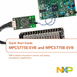
Quick Start Guide MPC5775E-EVB and MPC5775B-EVB
STEP-BY-STEP INSTRUCTIONS CONTINUED 5Connect the Power Supply Connect power supply to power socket and micro USB cable to micro USB port on the development board. Make sure the status LEDs D14, D15, D16 and D32 for volt…
MPC5775E RM MPC5775E/MPC5775B Reference Manual NXP website MPC5775E DS MPC5775E/MPC5775B Data Sheet NXP website AN12875 Getting Started with MPC5775E-EVB and MPC5775B-EVB NXP website OpenSDA OpenSDA User’s Guide NXP web…
Full PDF Document

If the inline viewer fails, it will open the original document in compatibility mode automatically. You can also open the file directly.
Extracted Text
Quick Start Guide
MPC5775E-EVB and MPC5775B-EVB
NXP evaluation boards for inverter and battery management applications.

Quick Start Guide GET TO KNOW THE MPC5775E-EVB BOARD

Motor Control Edge
Connector Analog Inputs
SDA Boot OpenSDA
UART JTAG
Ethernet TJA1100
2

RESET User LED

DSPI MC33FS6520

Figure 1: Front side of MPC5775E-EVB

eTPU/IO eMIOS/IO Power LED CAN
LIN
CAN 12 V Power In

www.nxp.com GET TO KNOW THE MPC5775B-EVB BOARD

Motor Control Edge
Connector
Analog Inputs
SDA Boot OpenSDA
UART JTAG
Ethernet
TJA1100

RESET User LED

DSPI MC33FS6520

Figure 2: Front side of MPC5775B-EVB

eTPU/IO eMIOS/IO Power LED CAN
LIN CAN 12 V Power In
3

Quick Start Guide

FEATURES OF THE MPC5775E-EVB AND MPC5775B-EVB BOARDS

� SPC5775B (MPC5775B-EVB) or SPC5775E (MPC5775E-EVB) silicon
� Requires 12 V external DC power supply (included in kit)
� MC33FS6520LAE system basis chip (SBC) for the board power supply
� SBC CAN physical interface (selectable [J48/J50] between FlexCAND/ MCAN1 [GPIO246 and GPIO247] or FLEXCANC [GPIO87 and GPIO88])
� Option to select CAN termination (J49)
� SBC LIN physical interface connected to RXDC/TXDC (J51/J54 connected by default).
� Master or slave mode supported (J52 VSUP connection)
� TJA1145T/CAN FD physical interface (selectable between FlexCANA/ MCAN0 GPIO83 and GPIO84] and FlexCANB [GPIO85 and GPIO86])
� TJA1100 automotive Ethernet PHY (physical interface)

� Debug selectable between external debug connection via JTAG or onboard OpenSDA (JTAG to USB interface)
� eMIOS header pins, ADC header pins and DSPI header pins
� MPC5775B-EVB only: MC33664 battery management system (BMS) interface
� MPC5775E-EVB only: eTPU header pins and motor control connector (x PCIe� style edge connector)

4

HARDWARE INCLUDED IN THE PACKAGE
1. One MPC5775E-EVB or MPC5775B-EVB

www.nxp.com

2. One 12 V Power supply 3. One micro USB cable 4. Standoffs
5

Quick Start Guide

STEP-BY-STEP INSTRUCTIONS FOR OUT OF BOX EXPERIENCE

1 Download Software
Download installation software and documentation under "Jump Start Your Design" at nxp.com/MPC5775E-EVB nxp.com/MPC5775B-EVB
2 Connect the USB Serial Cable
Connect the micro USB cable to J116 micro USB port.
Install the driver, if necessary, in order to make the COM port available as an OpenSDA port, which can be checked under "COM & LPT Ports" in Device Manager.
If the driver is available, user will be able to see the "OpenSDA � CDC Serial Port." Go to step 4.

Driver download link: http://www. pemicro.com/opensda/
3 To Install OpenSDA Driver Manually
Go to the Device Manager and rightclick the COM port detected and select Update Driver Software. Select Browse My Computer for driver software and select the OpenSDA driver that has been downloaded.
Driver download link: http://www. pemicro.com/opensda/
4 Setup Tera Term Console
Open Tera Term on Windows� PC. Select the serial port to which the micro USB of the development board is connected and click OK. Go to Setup>Serial Port and select 19200 as the baud rate.

6

www.nxp.com

STEP-BY-STEP INSTRUCTIONS CONTINUED

5 Connect the Power Supply
Connect power supply to power socket and micro USB cable to micro USB port on the development board. Make sure the status LEDs D14, D15, D16 and D32 for voltage levels 3.3 V, 5 V, 1.25 V and 12 V supply respectively are glowing green on the board.

6 Reset the Board
After resetting the board by pressing the Reset button (SW1), user will be able to see the following welcome message on the terminal.

7 Run Your First Example Project
Refer to the next slides.
7

Quick Start Guide SOFTWARE AND TOOL SUPPORT Software tools available:
� S32 Design studio for PowerPC from NXP � Download and install the NXP S32 Design Studio IDE � Built-in example codes available for many NXP power architecture products
Debug tools available:
� Onboard Open-SDA using micro USB (default) � Support Lauterbach, GHS and PE micro tools via JTAG interface Note: To use JTAG, user need to change the jumper configuration of J119
8

www.nxp.com

HOW TO RUN YOUR FIRST HELLO WORLD PROGRAM

Board configuration for the project
Connect J125-pin 2 to user LED header JP6-pin 2 with jumper wire.

LED header JP6

PIN

DESCRIPTION

1

5 V

2

LED D20

3

LED D21

4

LED D22

5

LED D23

6

GND

9

Quick Start Guide HOW TO RUN YOUR FIRST HELLO WORLD PROGRAM CONTINUED
1. Run Design Studio for Power Architecture�. 2. Make or select a workspace then Click "OK".
3. Start a "New" -> "S32DS Project from Example" from the File menu.
10

www.nxp.com HOW TO RUN YOUR FIRST HELLO WORLD PROGRAM CONTINUED
4. Scroll down to the "SDK PARTM v3.0.0 Example Projects," select "MPC5777C" and then select "Hello_world_mpc5777c". Then click "Finish."
11

Quick Start Guide HOW TO RUN YOUR FIRST HELLO WORLD PROGRAM CONTINUED
5. Click on the "Generate Processor Expert Code" icon.
12

www.nxp.com HOW TO RUN YOUR FIRST HELLO WORLD PROGRAM CONTINUED
6. Click on "Run -> Debug Configuration..." 7. Select "Debugger" tab 8. Select the "OpenSDA Embedded Debug � USB Port" interface
13

Quick Start Guide HOW TO RUN YOUR FIRST HELLO WORLD PROGRAM CONTINUED
After selecting the "OpenSDA Embedded Debug" interface, if the EVB is connected to the computer, the "Port" should automatically be selected. 9. Click "Apply." 10. Click "Debug." 11. Click "Yes."
14

www.nxp.com HOW TO RUN YOUR FIRST HELLO WORLD PROGRAM CONTINUED
12. Finally, click the "Resume" icon as shown below. Then user able to observe the blinking LED D20.
13. Click "Terminate" icon to terminate the program execution. 14. Click "C/C++" prospective view to back to program window.
15

Quick Start Guide

APPLICATION-SPECIFIC CONNECTIONS

� MPC5775B-EVB: Targeted for the Battery management system application evaluation
� MPC5775E-EVB: Targeted for the Inverter application evaluation
� Refer to the AN12875 application note for detailed information on the MPC5775BEVB and MPC5775E-EVB boards

APPLICATION SPECIFIC ITEM Motor control edge connector Battery management connector

MPC5775B-EVB Not supported
J118

MPC5775E-EVB J114
Not supported

16

www.nxp.com

REFERENCES

For further information on the EVBs, please refer to the following references.

DOCUMENT MPC5775E RM MPC5775E DS AN12875 OpenSDA S32DS
MC33FS6520LAE
FS65SBC-SDK-SW TJA1100 TJA1145 MC33664_SDS
MC33664 MC33771C RD33771CDSTEVB
BATT-14CEMULATOR HM2102NL HM2103NL

DESCRIPTION
MPC5775E/MPC5775B Reference Manual MPC5775E/MPC5775B Data Sheet
Getting Started with MPC5775E-EVB and MPC5775BEVB
OpenSDA User's Guide S32 Design Studio for Power Architecture v2.1 -
Windows/Linux MC33FS6520 System Basis Chip (Power Supply and
Drivers) Data Sheet FS6500/FS4500 Generic Embedded Software Driver
(Software Development Kit) TJA1100 100BASE-T1 PHY For Automotive Ethernet High-speed CAN transceiver for Partial Networking Isolated Network High-Speed Tranceiver Short Data
Sheet Isolated Network High-Speed Tranceiver Full Data
Sheet Battery Cell Controller Full Data Sheet Evaluation Board for MC33771C BCC with Isolated
Daisy Chain Communication 14-Cell Battery Pack Emulator to Supply MC33771C
BCC EVBs Pulse Electronics Dual BMS Transformer Pulse Electronics Single BMS Transformer

LOCATION NXP website NXP website NXP website NXP website NXP website
NXP website
NXP website NXP website NXP website NXP website
NXP website NXP website NXP website
NXP website Pulse Electronics Pulse Electronics
17

SUPPORT
Visit www.nxp.com/support for a list of phone numbers within your region.
WARRANTY
Visit www.nxp.com/warranty for complete warranty information.
AUTOMOTIVE COMMUNITY
Visit https://community.nxp.com/ community/s32
PRODUCT COMMUNITY
Visit https://community.nxp.com/ community/s32/MPC5xxx

Get Started
Download installation software and documentation under "Jump Start Your Design" at nxp.com/MPC5775E-EVB nxp.com/MPC5775B-EVB

nxp.com/MPC5775E-EVB nxp.com/MPC5775B-EVB
NXP and the NXP logo are trademarks of NXP B.V. All other product or service names are the property of their respective owners. Power Architecture is a trademark of International Business Machines Corporation, registered in many jurisdictions worldwide. � 2020 NXP B.V.
Document Number: MPC5775BEEVBQSG REV 0