722966 - PI-TRV
File info: application/pdf · 9 pages · 1.98MB
722966 - PI-TRV
Product Specification for PI-TRV
EWA1xxC-PO Configuration and Setup Instructions
EWA1xxC-PO Configuration and Setup Instructions 1 Introduction EWA1xxC-PO are a range of clip on modules for EW110 and EW171 Series water meters.
Extracted Text
EWA1xxC-PO Configuration and Setup Instructions
1 Introduction
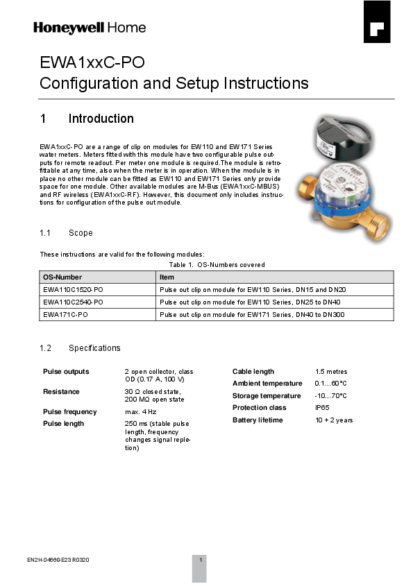
EWA1xxC-PO are a range of clip on modules for EW110 and EW171 Series water meters. Meters fitted with this module have two configurable pulse outputs for remote readout. Per meter one module is required.The module is retrofittable at any time, also when the meter is in operation. When the module is in place no other module can be fitted as EW110 and EW171 Series only provide space for one module. Other available modules are M-Bus (EWA1xxC-MBUS) and RF wireless (EWA1xxC-RF). However, this document only includes instructions for configuration of the pulse out module.
1.1 Scope
These instructions are valid for the following modules: Table 1. OS-Numbers covered
OS-Number
Item
EWA110C1520-PO
Pulse out clip on module for EW110 Series, DN15 and DN20
EWA110C2540-PO
Pulse out clip on module for EW110 Series, DN25 to DN40
EWA171C-PO
Pulse out clip on module for EW171 Series, DN40 to DN300
1.2 Specifications
Pulse outputs Resistance Pulse frequency Pulse length
2 open collector, class OD (0.17 A, 100 V)
30 closed state, 200 M open state
max. 4 Hz
250 ms (stable pulse length, frequency changes signal repletion)
Cable length Ambient temperature Storage temperature Protection class Battery lifetime
1.5 metres 0.1...60�C -10...70�C IP65 10 + 2 years
EN2H-0466GE23 R0320
1
GB 1.3 How to identify EWA1xxC-PO modules
1.4 Connection Diagram
2
EN2H-0466GE23 R0320
GB
2 Preparation
2.1 Required Parts
The following parts are required to change the configuration of the module: Table 3. Required parts
Part
Function
Programming interface Interface between PC (OS-No. EWA3001797) and module
USB cable
Connect programming interface to PC
Socket terminals (2)
Connect programming interface to module
Configuration software EWASET-PO
Readout current state values from module and program new values into module
Downloadable free of charge from https://homecomfort.resideo.com/sites/Europe/en-gb/Solu-
tions/Metering/Pages/Metering.aspx
EN2H-0466GE23 R0320
3
GB 2.2 Wiring to PC
Wiring between PC and module is done by a USB cable and programming interface EWA3001797.
Figure 1. Connection of programming interface
The cables are connected as follows:
Function Ground
Data
Table 4. Cable colours Wire colour pulse out module
Green Yellow
Wire colour interface Black
Black and red
To wire the module into the programmer normal strip terminals can be used. If a number of modules have to be programmed consider reusable socket terminals, for example Wago type 222 as in above example.
4
EN2H-0466GE23 R0320
GB 2.3 Installation of Programming Interface
When the programming interface is connected with the PC the driver is automatically installed and displayed as "Silicon Labs CP210x USB to UART Bridge". The COM port used can be checked in the device manager of the PC. In below example it is COM6.
Figure 2. Device manager When the software EWASET-PO has been installed and the module connected it can be parametrised. Parametrisation is not mandatory, if the module is not parametrised standard values are applied (see Chapter 1.5 Standard Values above). The parametrisation software is available for free download in the download area of the RESIDEO metering website under https://homecomfort.resideo.com/sites/Europe/en-gb/Solutions/Metering/Pages/Metering.aspx.
EN2H-0466GE23 R0320
5
GB
3 Programming
3.1 Wake up
NOTE: This chapter applies only to modules produced before August 2015. After production the module is put into sleep mode to save battery life. Before programming or installation briefly place a magnet near the reed switch of the module. By this the module is woken up from sleep mode.
Figure 3. Position of reed switch in module EWA110C1520-PO and EWA110C2540-PO
Figure 4. Position of reed switch in module EWA171C-PO
Figure 5. Briefly place magnet near reed switch
3.2 Software
The pulse out module configuration software is a simple tool with only few functions:
Figure 6. Screenshot of parametrisation program
6
EN2H-0466GE23 R0320
3.2.1 Fields
Field No. 1 2 3 4 5 6 7
Field name Watermeter Range Outputs Read configuration COM port setting Units Perform
GB
Table 5. Overview of fields
Field type
Function
Pulldown
Defines meter connected to module
Pulldown
Selection of pulse value
Pulldown
Selection of pulse output 1 and 2
Execute button
Read and display configuration of module
Pulldown
Selection of COM port
Radio buttons
Selection of unit for pulse value
Execute button
Write data into module
3.2.2 Field Description 3.2.2.1 Watermeter Required to select type of water meter connected and in that way define range limits.
Figure 7. Pulldown of field "Watermeter"
3.2.2.2 Range and Unit
Allows selection of pulse value within a given range based on meter size (see field Watermeter above). Acceptable ranges are:
Table 6. Pulse value ranges and increments
OS-No.
For DN sizes
Pulse value range
Increment
EWA110C1520-PO
15...20
1...255 litres
1 litre
EWA110C2540-PO
25...40
100...25 500 litres
100 litres
EWA171C-PO
40...125
100...25 500 litres
100 litres
EWA171C-PO
150...300
1...255 m�
1 m�
The unit can be selected independently by pressing the radio button for "Litres per pulse" or cubic metres per pulse ("m� / pulse").
EN2H-0466GE23 R0320
7
GB
3.2.2.3 Standard Values
OS-No. EWA110C1520-PO EWA110C2540-PO
EWA171C-PO EWA171C-PO
For DN sizes 15...20 25...40 40...125
150...300
Table 2. Standard values Pulse value 1 litre 100 litres 100 litres 1 m�
Output 1 IB IB IB IB
Output 2 PR PR PR PR
NOTE: Meaning of output types is explained in chapter 3.2.2.3 on page 8.
3.2.2.4 Output 1 and Output 2
Defines type of output for pulse output 1 and pulse output 2. Both pulse outputs can be programmed with any value. Available values are:
Table 7. Output pulse types
Value
Function
IB � Balance impulse
Only forward flow pulses are sent. Backward flow pulses are compensated by suspending forward flow pulses of same value.
WP � Forward flow impulse
Only forward flow pulses are sent.
WS � Backward flow impulse
Only backward flow pulses are sent.
PR � Flow impulse
Any flow pulse is sent, regardless of direction.
PT � Forward and backward flow impulse
Only backward flow pulses are sent. Forward flow pulses are compensated by suspending backward flow pulses of same value.
SK � direction state
A pulse is sent at change of flow direction.
AW � failure state
A pulse is sent when a failure is detected.
8
EN2H-0466GE23 R0320
GB
3.2.2.5 Read configuration Current configuration of the pulse out module is read and shown on the display in a separate window.
Figure 8. Window with configuration information It may take several retries until the configuration window appears. The reason is that the module only checks once per minute if it is connected to a programming interface. Retries are done automatically, standard value is 20 retries, with 5 000 ms time between each retry. 3.2.2.6 COM Port Allows to select the COM port to which the programmer is connected. (Also see chapter 0 above.) Press "Refresh COM" button in case COM port used is not shown in drop down list. 3.2.2.7 Perform When all inputs have been done the data is written onto the module by pressing the "Perform" button.
Manufactured for and on behalf of Pittway Sarl, Z.A., La Pi�ce 4, 1180 Rolle, Switzerland by its authorised representitive Ademco 1 GmbH
�2020 Resideo Technologies, Inc. All rights reserved.
For more information homecomfort.resideo.com/europe Ademco 1 GmbH, Hardhofweg 40, 74821 MOSBACH, GERMANY Phone: +49 6261 810 Fax: +49 6261 81039
Subject to change. EN2H-0466GE23 R0320