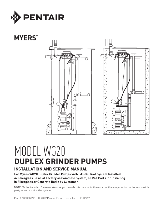
Pentair Myers WG20 Duplex Grinder Pumps
Installation and Service Manual
This manual provides comprehensive instructions for the installation and service of Pentair Myers WG20 Duplex Grinder Pumps equipped with a Lift-Out Rail System. This system is designed for installation in fiberglass basins (as a complete factory-installed system) or for installation in fiberglass or concrete basins using provided rail parts.
Note to the Installer: Please ensure this manual is provided to the equipment owner or the responsible party maintaining the system.
System Components and Preparation
Complete packaged systems, including fiberglass basins, typically have all parts mounted except for the pump and level controls. Piping and guide plates for pumps are shipped separately and must be ordered specifically for duplex systems (two packages required).
Level controls must be ordered separately and mounted in the basin. Controls are specified at the time of order, with appropriate brackets pre-mounted for support. For mercury float controls, three are required. An optional alarm control must also be specified at the time of order for bracket mounting.
Control boxes and pumps are selected based on voltage, phase, and whether NEMA 3R enclosure is required.
CALIFORNIA PROPOSITION 65 WARNING:
WARNING: This product and related accessories contain chemicals known to the State of California to cause cancer, birth defects, or other reproductive harm.
Steps to Install Rail System in Fiberglass or Concrete Basin
- Unpack all parts and verify against the parts list. Use the provided full-size paper template to accurately locate bolting for discharge castings and establish vertical center lines for flanges. Drop a plumb line from the basin rim cover holes to locate base castings.
- Thoroughly clean the basin bottom before placing the paper template. For concrete basins, chip away any protruding rocks. Punch through the paper template to mark bolt hole locations. Drop a plumb line from the top of the basin to mark center lines on the basin wall with chalk. For fiberglass basins, ensure they are mounted on a level surface with plumb walls before marking. All parts should be installed in a fiberglass basin before placing it in the ground.
- For concrete basins, drill holes in the basin bottom and side walls for mounting parts. Use 1-1/2" long, 3/8" size machine bolt expansion sleeves and a 5/8" carbide drill bit. For fiberglass basins, rubber seal washers are provided for hold-down bolts.
- Cut holes through the concrete wall or fiberglass basin wall to accommodate discharge and support flanges. Pipes can be cemented directly into the wall if flanges are not used.
- Bolt discharge cases to the basin bottom. Use provided seal washers for fiberglass basins to seal bolt heads where bolts pass through the basin bottom. Secure all flanges, but do not fully tighten bolts at this stage to allow for adjustment when rails are placed.
- Install discharge piping from the base casting to the discharge flange. Ensure vertical piping is plumb to avoid interference with rail guide pipes. Use a slip coupling to join pipes.
- Install 1" galvanized pipe rails. Stainless steel or other corrosion-resistant pipe of the same outside diameter (1.315") may be used. To mount the rail support bracket, place the yoke in the rails, push the support nipple through the yoke, and screw into the mounting flange. Loosen flange bolts for alignment if necessary. If pipe is cemented in, ensure all piping is in place, plumbed, and blocked before final cementing.
- Align the 1" rails vertically using a level in both directions. Adjust the rail support yoke as needed. Once rails are properly aligned, tighten all bolts in base castings and flanges.
- Mount level control support brackets and install level controls on the brackets. Set SM25NO controls at the appropriate levels.
- If the basin cover is used for mounting the control box directly, attach the aluminum connection box to the 2" elbow supplied with the cover before mounting the cover to the basin.
- Place the cover on the basin and bolt it in place. For concrete basins, ensure expansion sleeves are installed at the correct bolt locations.
- Mount the inlet flange at the depth required for gravity flow into the basin. Flanges are available for 4", 6", or 8" pipes, and multiple inlets can be used. The inlet hole is cut and the flange is mounted in the field.
Cubic feet of concrete poured around basin to prevent flotation:
| BASIN DIA. | CUBIC FEET OF CONCRETE REQUIRED PER FOOT OF BASIN DEPTH |
|---|---|
| 24" | 2 |
| 30" | 3.5 |
| 36" | 5 |
| 48" | 8.5 |
Example: A 24" diameter basin, 8 ft. deep requires 2 x 8 = 16 cu. ft. of concrete to prevent flotation. If the basin is installed in dry ground without surface water, 1/3 of the above values may be used.
Assembling Piping to Pump
Pump grinder plate and pump discharge piping are supplied with other rail parts.
- Attach the guide plate and piping to the pump. Ensure piping is plumb and tighten all set screws. Attach the lifting chain to the lifting eye using the supplied clevis. Pumps can now be lowered into position using the lifting chain. Retain power and control cords at the surface as the pump is lowered.
- When pumps are in place, attach cords to the connection box. Remove slack from wires to prevent tangling and ensure they hang vertically.
- Connect level control cords to the connection box as shown in the wiring diagrams.
- Install the control box on the cover and connect it to the cover using a 2" conduit.
- Run wires to the control box and connect them to the incoming cords. Mark or trace each incoming wire for correct connection.
- Do not pour sealing compound into the fitting until the pumps have been run and all connections are confirmed correct.
Note: If the control box is to be installed off-set from the basin, the CF-200 conduit flange must be installed in the basin, and the connection box connected to the flange before installing the cover.
- Install hold-down guides and 1/2" galvanized hold-down pipe. Screw the pipe into the lower guide. Secure upper guides to the rails and the hold-down pipe with set screws. The hold-down pipe is essential to prevent hydraulic pressure from lifting the pump from the base seal casting. This hydraulic pressure keeps the pumps suspended during operation, reducing side load on the rails and facilitating easier removal when needed.
- Connect the valve adapter and shut-off handles using 1/2" galvanized pipe, secured with set screws. These shut-off stems are installed in 1-1/2" plastic pipe guides attached to the valves.
Starting System
- Open the 1-1/4" bronze gate valves by turning them counter-clockwise.
- Set pump switches to the 'Auto' position and add water to the sump until the level controls activate one pump. Allow the pump to operate until the sump level drops and the pump stops.
IMPORTANT: The lower level control or weight should be set so that the sump level drops to within 1" or 2" from the bottom of the pump before it stops.
- Turn both pump switches to 'Off'. Fill the sump until the level overrides the control, then turn both pump switches to 'Auto'. Both pumps should activate and operate until the sump level drops to the 'Off' position.
- Leave both pump switches in the 'Auto' position. The system is now ready for automatic operation.
Troubleshooting
Pumps will run but not deliver water:
- Air Lock: Try starting and stopping the pump several times. If the issue persists, turn both pumps 'Off', add 6" to 12" more water to the sump. If air still doesn't clear, it may be necessary to raise the hold-down pipe and lift the pump so the lower seal fitting is out of the discharge case to release trapped air.
- Ensure the shut-off valve in the discharge line is open.
- For 3-phase pumps, verify correct rotation. The grinder impeller must rotate counter-clockwise when viewed from the pump inlet. Keep fingers away from the grinder impeller.
Pump seal fitting does not hold tight:
- Check for a cut or broken O-ring and replace if necessary. Debris may be caught in the seal flange. Lift the pump, open the shut-off valve, and backflush the discharge casting.
- If the discharge line is not filled upon installation, lift the pump until the seal flange is out of the discharge case, then run the pump to flush the casting.
For all other pump or control box issues, refer to the specific instructions included with those components.
CAUTION: Always turn off power before working on pumps or controls. If the pump is remotely located from the control box, disconnect the pump wires to ensure power cannot be accidentally turned on. Never place fingers near the grinder impeller when the pump cord is connected.
Diagrams and Illustrations
Detailed diagrams illustrating the Myers Duplex Lift-Out Rail System in 36" or 48" concrete and fiberglass basins are provided, showing component placement, dimensions, and connections. These diagrams include:
- Top and side views of the system in various basin types.
- Detailed views of rail support flanges, yokes, guide plates, and discharge castings.
- Wiring diagrams for duplex grinder systems with ALC switch and FLC alarm controls, and FLCW 4 ball control.
- A parts list for RWG & RWGX 125 Rail System for 2HP Grinder Pumps, detailing each component with reference numbers and part numbers.
Standard Limited Warranty
Pentair Myers warrants its products against defects in material and workmanship for a period of 12 months from the date of shipment or 18 months from the manufacturing date, whichever occurs first. This warranty is valid only when products are used in compliance with Pentair Myers' technical manuals for pumping non-abrasive, non-corrosive liquids.
During the warranty period, Pentair Myers will, at its discretion, repair or replace defective parts. Pentair Myers reserves the right to change product designs without obligation to provide such changes for previously sold units.
Warranty claims may require start-up reports and electrical schematics, submitted via the Pentair Myers website. The warranty is void if Pentair Myers authorized control panels are not used, or if seal fail and heat sensing devices are not functional and monitored. Pentair Myers covers only the lower seal and associated labor for dual seal pumps. Costs for field labor, travel, rented equipment, removal/reinstallation, or freight are not covered.
The limited warranty does not apply to defects or malfunctions resulting from:
- Failure to properly install, operate, or maintain the unit per instructions.
- Abuse, accident, or negligence.
- Normal maintenance services or parts.
- Installation not in accordance with applicable local codes or good trade practices.
- Moving the unit from its original installation location.
- Using the unit for purposes other than its designed application.
- Repairs or alterations by unauthorized personnel or use of non-factory specified parts.
Pentair Myers expressly disclaims all warranties, express or implied, including the implied warranties of MERCHANTABILITY and FITNESS FOR ANY PARTICULAR PURPOSE.
Pentair Myers shall not be liable for consequential, incidental, or special damages, including personal injury or property damage resulting from improper installation. Pentair Myers recommends professional installation.
Some states may not allow limitations on incidental or consequential damages, so these limitations may not apply to all users.
Contact Information
Pentair Myers
1101 Myers Parkway
Ashland, Ohio, USA 44805
419-289-1144
www.femyers.com
490 Pinebush Road, Unit #4
Cambridge, Ontario, Canada N1T 0A5
800-363-PUMP
Related Documents
 |
Pentair Myers RG-10 Grinder Pump Installation and Service Manual Installation and service manual for the Pentair Myers RG-10 1 HP Grinder Pump for Residential Applications. Includes usage, safety warnings, component descriptions, power supply information, troubleshooting guide, and limited warranty. |
 |
Pentair Myers D25-8 and D40-8 Industrial Pumps: Instructions and Service Manual This comprehensive manual provides detailed instructions and service information for Pentair Myers D25-8 and D40-8 industrial pumps. It covers installation, operation, maintenance, troubleshooting, and parts lists to ensure optimal performance and longevity of these pumps. |
 |
Pentair Myers Model E-10 1.0 HP Effluent Pump Installation and Service Manual Detailed installation, service, and troubleshooting guide for the Pentair Myers Model E-10 1.0 HP submersible wastewater effluent pump. Covers product usage, safety, power, maintenance, troubleshooting steps, parts list, and warranty information. |
 |
Pentair Myers Reciprocating Pumps Repair Kits and Parts Guide Comprehensive guide to Pentair Myers reciprocating pump repair kits and parts, detailing components and ordering information for various pump series including BXM, CX, C25/35/40, D35/50/60/65, E54/70/80/110, CXP, CPM, and DP. |
 |
Pentair Myers DP Series Industrial Plunger Pump Installation and Service Manual Comprehensive guide for installing, operating, maintaining, and troubleshooting Pentair Myers DP Series industrial plunger pumps. Includes detailed instructions, maintenance schedules, parts lists, troubleshooting charts, and warranty information. |
 |
Pentair Myers PA-1 and PA-2 Alarm Panels Installation and Service Manual Installation and service manual for Pentair Myers PA-1 (115V) and PA-2 (230V) alarm panels. Covers application, enclosure, components, wiring diagrams, and standard limited warranty. |
 |
Pentair Myers Pumps & Accessories Price List Comprehensive price list for Pentair Myers pumps and accessories, including sump pumps, utility pumps, specialty pumps, effluent pumps, sewage pumps, and solids handling pumps. Details specifications like HP, voltage, cord length, discharge size, and solids handling capacity. |