Read these instructions carefully. Failure to follow them could damage the product or cause a hazardous condition. 2. Check the ratings given in the instructions and on the product to make sure the product is suitable for your application. 3. Installer must be a trained, experienced service technician. 4.
25 nov 2020 — Read these instructions carefully. Failure to follow them could damage the product or cause a hazardous condition. 2. Check the ratings given in the ...
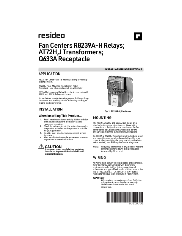
Fan Centers R8239A-H Relays; AT72H,J Transformers; Q633A Receptacle

APPLICATION
R8239 Fan Center--use for heating, cooling or heatingcooling system. AT72H,J Plate-Mounted Transformer-Relay Receptacle--use when cooling will be added later. Q633A Plate-mounted Relay Receptacle--use to install R8222 and R8228 Relays on J boxes. Above devices provide low voltage control of line voltage fan motors and auxiliary circuits in heating, cooling, or heating-cooling systems.

INSTALLATION INSTRUCTIONS

INSTALL ATION
When Installing This Product...
1. Read these instructions carefully. Failure to follow them could damage the product or cause a hazardous condition.
2. Check the ratings given in the instructions and on the product to make sure the product is suitable for your application.
3. Installer must be a trained, experienced service technician.
4. After installation is complete, check out operation as provided in these instructions.
CAUTION
Disconnect power supply before beginning installation to prevent electrical shock and equipment damage.

Fig. 1. R8239A-H, Fan Center.
MOUNTING
The R8239, AT72H,J and Q633A1007 mount on a standard 4 inch square junction box. Make wiring connections in the junction box, then fasten the fan center to the box, placing the junction box screws through notches in the fan center mounting plate. On Q633A or AT72H,J Receptacles without relays, select and mount the appropriate relay and attach the relay cover. A label identifying the relay used (furnished with select models) should be applied to the relay cover. NOTE: Relay may be mounted in any position. With the
terminals pointing down, pickup voltage is increased by 12 percent.
WIRING
All wiring must comply with local codes and ordinances. Refer to information furnished with the system equipment or refer to Figs. 2-6 showing internal schematics and typical hookups for the fan centers. See Fig. 5--R8239F; Fig. 7--Q633A1007; Fig. 9--typical hookup for R8239D in an intermittent Pilot system. IMPORTANT
When making external connections to the line voltage leadwires of this device, use only Underwriters Laboratories Inc. listed connectors.

60-1190-01

FAN CENTERS R8239A-H RELAYS; AT72H,J TRANSFORMERS; Q633A RECEPTACLE

R8239 Replacement

Componentsa Relay Relay

Fan Transformer and Horse

Center

Receptacle

power

Table 1. R8239 Model Description.

Switching

Pole

Leadwire color

R8239A AT72H/R8222B 3/4

SPDT

Black--common

--

Red--N.O. contact

Brown--N.C. contact

R8239B AT72J/R8222D 3/4

DPDT

Pole 1 Pole 2

Black--common Red--N.O. contact Brown--N.C. contact Violet--common Red/Yellow--N.O. contact Yellow--N.C. contact

R8239C AT72H/R8222A 3/4

SPST, N.O.

--

Both leadwires black--N.O.contact

R8239D AT72J/R8222U

DPST, 1 N.O. power

Pole 1 (power pole)

Both leadwires black--N.O.contact

3/4

contact, 1 N.O. pilot duty
contact

Pole 2 (pilot duty pole)

Both leadwires red--N.O.contact

R8239E AT72J/R8222F 3/4 DPST 1 N.O., 1 N.C.

Pole 1 Pole 2

Both leadwires black--N.O.contact Both leadwires red--N.C.contact

R8239F AT72J/R8228C 3/4

DPST Both N.C.

Pole 1 Pole 2

Both leadwires black--N.O.contact Both leadwires red--N.O.contact

R8239G AT72H/R8228A

1b SPST, N.O. contact

--

Both leadwires black--N.O.contact

R8239H AT72H/R8228B

1b

SPDT

Black--common

--

Red--N.O. contact

Brown--N.C. contact

a At72H,J and appropriate relay can be ordered separately. b 1 hp at 120 Vac; 2 hp at 240 Vac.

See Wiring Diagram Fig. 2
Fig. 3
Fig. 4 Figs. 5,9
Fig. 6 Fig. 5 Fig. 4 Fig. 2

PLENUM SWITCH OR OTHER SWITCHING DEVICE
BROWN
RED
,
I I I I

ISOLATION RELAY

I
,

1

I

HEATING CONTROL
T

T87F THERMOSTAT

TWO-SPEED FAN MOTOR

1 PROVIDE DISCONNECT MEANS AND OVERLOAD PROTECTION AS REQUIRED
2 USE OPTIONAL HOOKUP WITH ISOLATING RELAY (DASHED LINE) IF HEATING CONTROL HAS A SEPARATE POWER SUPPLY. ISOLATION OF THE POWER SUPPLIES MAY ALSO BE ACCOMPLISHED BY USING SPECIAL THERMOSTAT SUBBASE COMBINATIONS WITH ISOLATED CIRCUITS (SUCH AS T87F-Q539A1147, T834A-Q634A1039, T822A-Q611A1037). REFER TO SPECIFICATION SHEETS FOR DETAILS 4648A
Fig. 2. R8239A,H typical hookup with 2-speed fan in heating-cooling system.

HUMIDISTAT

OR
COMPRESSOR cONTROL

1 PROVIDE DISCONNECT MEANS AND OVERLOAD PROTECTION AS REQUIRED

2 USE OPTIONAL HOOKUP WITH ISOLATING RELAY (DASHED LINE) IF HEATING CONTROL HAS A SEPARATE POWER SUPPLY. ISOLATION OF THE POWER SUPPLIES MAY ALSO BE ACCOMPLISHED BY USING SPECIAL THERMOSTAT SUBBASE COMBINATIONS WITH ISOLATED CIRCUITS (SUCH AS T87F-Q539A1147, T834A-Q634A1039, T822A-Q611A1037).
Fig. 3. R8239B typical hookup with 2-speed fan. "TOTAL COMFORT" application provided with electronic air cleaner, humidifier and blower motor.

60-1190--01

2

FAN CENTERS R8239A-H RELAYS; AT72H,J TRANSFORMERS; Q633A RECEPTACLE
RELAY
FAN MOTOR

1 PROVIDE DISCONNECT MEANS AND OVERLOAD PROTECTION AS REQUIRED

2 USE OPTIONAL HOOKUP WITH ISOLATING RELAY (DASHED LINE) IF HEATING CONTROL HAS A SEPARATE POWER SUPPLY. ISOLATION OF

THE POWER SUPPLIES MAY ALSO BE ACCOMPLISHED BY USING

SPECIAL THERMOSTAT SUBBASE COMBINATIONS WITH ISOLATED

CIRCUITS (SUCH AS T87F-Q539A1147, T834A-Q634A1039, T822A-Q611A1037).

REFER TO SPECIFICATION SHEETS FOR DETAILS

4650A

Fig. 4. R8239C,G typical hookup with 1-speed fan in heating-cooling system.

TO AUXILIARY

RELAY

FAN AND LIMIT CONTROLLER

OR COMPRESSOR CONTROL PANEL

1 PROVIDE DISCONNECT MEANS AND OVERLOAD PROTECTION AS REQUIRED

2 USE OPTIONAL HOOKUP WITH ISOLATING RELAY (DASHED LINE) IF HEATING CONTROL HAS A SEPARATE POWER SUPPLY. ISOLATION OF THE POWER SUPPLIES MAY ALSO BE ACCOMPLISHED BY USING SPECIAL THERMOSTAT SUBBASE COMBINATIONS WITH ISOLATED CIRCUITS (SUCH AS T87F-Q539A1147, T834A-Q634A1039, T822A-Q611A1037). REFER TO SPECIFICATION SHEETS FOR DETAILS

Fig. 6. R8239E typical hookup with 2-speed fan and limit controller in heating-cooling system.

On Q633A1007 Plate-mounted Relay Receptacle, leadwires are provided for additional relay pole positions. Insert the `required leadwires in the relay receptacle as follows.

Determine the leadwire colors required for the relay and application desired (Fig. 7). Push the leadwire terminal into the receptacle plate from the side stamped with the color code (Fig. 8). When inserting the leadwire, the tang on the quick-connect terminal must align with the small clearance slot in the terminal opening.

Press the terminal in until it locks in place.

CHECKOUT

1 PROVIDE DISCONNECT MEANS AND OVERLOAD PROTECTION AS REQUIRED

2 USE OPTIONAL HOOKUP WITH ISOLATING RELAY (DASHED LINE) IF HEATING CONTROL HAS A SEPARATE POWER SUPPLY. ISOLATION OF THE POWER SUPPLIES MAY ALSO BE ACCOMPLISHED BY USING SPECIAL THERMOSTAT SUBBASE COMBINATIONS WITH ISOLATED CIRCUITS (SUCH AS T87F-Q539A1147, T834A-Q634A1039, T822A-Q611A1037). REFER TO SPECIFICATION SHEETS FOR DETAILS

3 TO AUXILIARY CIRCUIT. MAYBE USED AS A LCOKOUT CONTACT TO PREVENT AN ELECTRIC STRIP HEATER FROM OPERATING UNLESS THE FAN MOTOR IS OPERATING, OR AS CONDENSING UNIT SWITCHING MEANS.

4651

Fig. 5. Typical hookup R8239D with 1-speed fan in heating-cooling system and pilot duty contacts to power
auxiliary circuit. R8239F is similar, but has 2 normally open power rated contacts.

Always conduct a thorough checkout when installation is complete. Place the system into operation. Operate the system through at least one complete cycle to make sure that the system equipment and the fan center operates as intended.
SERVICE
CAUTION
Disconnect the power supply to prevent electrical shock and equipment damage. The relay in the R8239 is field replaceable. See Table 1 on page 2 section for appropriate relay. To replace the relay use the following procedure: 1. Remove the 2 relay cover screws and remove the cover. 2. Remove the plug-in relay from the receptacle, and replace with new relay. 3. Replace the cover and 2 screws removed in step 1.

3

60-1190--01

FAN CENTERS R8239A-H RELAYS; AT72H,J TRANSFORMERS; Q633A RECEPTACLE

GENERAL PURPOSE

TYPICAL HOOKUP WITH FAN

SPEED

COM. TO

FAN MOTOR

RED

LO

cOIL

TO 24V TERM ON

GENERAL PURPOSE RELAY

TYPICAL HOOKUP WITH 2 SPEED FAN

BLK

FAN

H I RED

MOTOR

LO BRN

cOIL

TO 24V TERM. ON THERM-

GENERAL PURPOSE RELAY

GENERAL PuRPOSE RELAY

TYPICAL HOOKUP WITH 2 SPEED FAN

BLK

FAN

HI RED

MOTOR

COIL

TO TERM. ON THERM-

COM. TO
HI RED
MOTOR LO

2

COIL

TO TERM.
C-G ON THERM.

AUX. LOAD

RED YE YEL

NOTE: DO NOT INTERCONNECT WITH OTHER LOW VOLTAGE POWER SUPPLIES. IF HEATING CONTROL HAS AN INTEGRAL POWER SUPPLY REFER TO WIRING INSTRUCTION. 6472
Fig. 7. Q633A1OO7 receptacle plate wiring hookups with typical relays.

RED LEADWIRE
BLACK LEADWIRE

TRANSFORMER MOUNTING HOLE COVER

VIOLET LEADWIRE

BLUE LEADWIRES

TANG

RECEPTACLE CLEARANCE SLOT

QUICK CONONN ECT TERMINAL ON LEADWIRE

6473

Fig. 8. R8239E typical hookup with 2-speed fan and limit controller in heating-cooling system.

Fig. 9. Typical hookup for R8239D used as isolating relay in an intermittent pilot system.

www.resideo.com

Resideo Technologies, Inc. 1985 Douglas Drive North, Golden Valley, MN 55422 1-800-468-1502 60-1190--01 M.S. Rev. 06-20 | Printed in United States

© 2020 Resideo Technologies, Inc. All rights reserved. This product is manufactured by Resideo Technologies, Inc. and its affiliates.