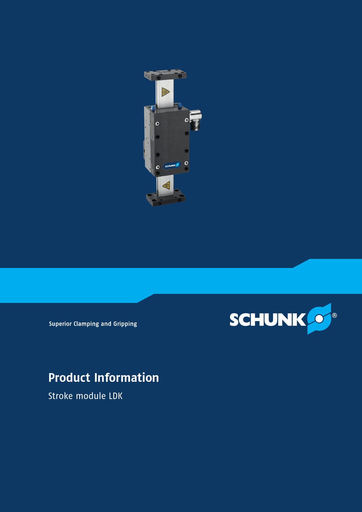
SCHUNK LDK Stroke Module: Product Information
Superior Clamping and Gripping
Flexible. Reliable. Fast.
Stroke module LDK
Compact short stroke axis with linear motor and roller guidance
Field of application
For use in clean and slightly polluted environments. Suitable for faster and precise moving or controlled press-in operation of workpieces in high-speed assembly, measurement and testing technology, microelectronics, or medical technology.
Advantages – Your benefits ?
- Almost no wear parts: For long service life and reliability of the system.
- No mechanical play: Between the drive components for flexible response behavior and high positioning accuracy.
- Low oscillations and high holding force: For the shortest positioning times and process stability.
- Integrated motor and measuring system: In the axis minimizes interfering contours and space requirements.
- Absolute stroke measuring system: Less programming effort and time saving during commissioning and operation.
- High dynamics: For shorter cycle times, leading to high productivity.
- Many different variants: Possible, e.g., long slides for special optimization for specific applications.
- Optional pneumatic holding brake: Acts as a rod lock for process reliability during system downtime.
- Optional certified safety devices: According to SIL2/PLd with HIPERFACE® and DRIVE-CLiQ interfaces for applications with high standards in machine safety.
Key Specifications:
- Sizes: 1 Quantity
- Max. stroke: 200 mm
- Max. driving force: 250..500 N
- Repeat accuracy: ±0.01 mm
- Max. speed: 4 m/s
Functional description
The electric drive consists of a primary part (motor coil) and a secondary part (permanent magnets). The controller manages the phase and amplitude of the applied electric current to set the profile, fitted with magnets, in motion.
- 1 Pneumatic holding brake: For maintaining position during downtime.
- 2 High precision, hardened and ground steel guide rails: For optimal guidance properties and speeds.
- 3 Integrated secondary parts: With high power magnets.
- 4 Compact primary part slide: With mounting surfaces, scope-free adjusted rollers, and integrated measuring system.
- 5 End plates: For mounting sensors, shock absorbers, and additional attachments.
- 6 Motor plug: Position right/left can be selected.
Detailed functional description
Design of the linear direct axis
The linear direct axes of the LDx product series (illustration corresponds to linear module LDN) comprise a motor slide with an integrated primary part and measuring system. The secondary part consists of permanent magnets and is integrated into the axis profile of the linear axis.
- 1 Axis profile: (e.g., steel guide rail or aluminum profile)
- 2 Permanent magnets with dirt cover
Modular transducer system
The linear module (similar to illustration) is available with four different stroke measuring systems. The incremental stroke measuring system has a 1Vss interface. Absolute path measuring systems are optionally available with HIPERFACE®, SSI, or DRIVE-CLiQ interfaces.
- 1 Measuring system reading head: Fixed on the motor slide
- 2 Measuring system tape measure: Fixed on the aluminum profile
Pneumatic holding brake
Optionally, the linear module (similar to illustration) is equipped with a pneumatically actuated holding brake. Its function is activated in a non-ventilated state and is used to maintain the position of the linear axis in a currentless state.
- 1 Holding brake: Operated pneumatically
Drag chain
Matching cable tracks are available as accessories for the linear axes (similar to illustration). These are adapted to the respective effective stroke, supplied with mounting material, and if necessary, pre-assembled.
- 1 Drag chain
Ordering example
Example: LDK - EL - 0100 - 270 - 0500 - 1 - LXBV - 111A - SB03 - 0132
Axis version:
- LDH: linear direct drive with narrow short-stroke profile
- LDK: linear direct drive with short-stroke profile
- LDN: linear motor drive with single X profile
- LDM: Linear direct drive with double X-profile
- LDT: Linear direct drive with triple X-profile
- LDL: Linear direct drive with flat profile
Guidance and motor versions:
- E: non-supported version
- U: supported version
Slide length:
- S: standard slide
- L: Long slide
Size, Nominal stroke, Overall length, Number of active slides: (Refer to specific model codes)
Option group 1:
- Number 1: Motor option
- Number 2: Additional passive slides option
- Number 3: On option holding brake in active slide
- Number 4: On option valve
Option group 2:
- Number 1: Reference switch option
- Number 2: Limit switch option
- Number 3: On option drag chain
- Number 4: On option wipers
Option group 3:
- Number 1: Shock absorbers option
- Numbers 2 - 4: Mounting strips
Option group 4 Measuring system:
- Number 1: stroke measuring system
- Number 2: Position measurement system
- Number 3: Cable length
- Number 4: Controller interface
General notes about the series
Drive: Linear direct drive based on a 3-phase, electronically commutated and permanently excited AC synchronous liner motor.
Stroke measuring system: Contactless, magnetic measuring system with incremental and absolute variants; with HIPERFACE®, SSI, 1Vss and DRIVE-CLiQ interfaces.
Profile: Width of steel guide rail.
Slide: Aluminum slide, primary part and measuring system reading head directly integrated.
Scope of delivery: Accessory pack with centering sleeves and assembly and operating manual with declaration of incorporation.
Drive controller: Bosch Rexroth IndraDrive and Siemens SINAMICS drive control units supported as standard; matching parameters supplied on DVD, other manufacturers available on request.
Warranty: 24 months.
Repeat accuracy: Defined as the spread of the target position after 100 consecutive positioning cycles under constant conditions.
Ambient conditions: The modules are mainly designed for use in clean ambient conditions. Life time may shorten in harsh ambient conditions, and SCHUNK cannot assume liability in such cases. Contact SCHUNK for assistance.
Layout or control calculation: Verifying the sizing of the selected unit is necessary to avoid overloading. Contact SCHUNK for assistance.
Application example
Linear gripper rotary unit for dynamic movement of small components.
- 1 2-finger parallel gripper MPG-plus
- 2 Miniature rotary module ERD
- 3 Stroke module LDK
- 4 Universal linear module LDN
- 5 Universal linear module LDT
SCHUNK offers more ...
The following components make the product LDK even more productive – providing suitable additions for the highest functionality, flexibility, reliability, and controlled production.
- Gripper for small components
- Universal gripper
- Rotation unit
- Rotary gripper module
- Power and encoder cables
- Drive controller
- Drag chain
- Pillar assembly system
For more information on these products, visit schunk.com or contact the SCHUNK technical hotline at +49-7133-103-2696.
Options and special information
Modular transducer system: The linear module is available with four different stroke measuring systems. Incremental systems use a 1Vss interface. Absolute path systems are optionally available with HIPERFACE®, SSI, or DRIVE-CLiQ interfaces.
Pneumatic holding brake: An optional holding brake, pneumatically actuated, maintains the linear axis position in a currentless state.
Supported axis version: The axis profile can receive additional support for high payloads, minimizing bending and providing an alternative mounting option.
Certified encoder system: Encoder systems with HIPERFACE® (optional) and DRIVE-CLiQ interfaces are certified according to SIL2/PLd, suitable for demanding applications with high machine safety requirements. Contact SCHUNK for further information.
Dimensions and maximum loads
Diagram shows a schematic of the linear axis with force vectors (Fx, Fy, Fz) and torque vectors (Mx, My, Mz) and key dimensions (Xmax, Z, X+H).
For values, see technical data table. The forces and torques shown are maximum values for static loading.
Technical data
| Description | LDK-ES-0100 | LDK-EL-0200 |
|---|---|---|
| Drive concept | Linear direct drive | Linear direct drive |
| Max. stroke H [mm] | 200 | 200 |
| Max. driving force [N] | 250 | 500 |
| Nominal force [N] | 115 | 185 |
| Max. useful load (vertical) [kg] | 3 | 6 |
| Repeat accuracy [mm] | ±0.01 | ±0.01 |
| Max. speed [m/s] | 4 | 4 |
| Max. acceleration [m/s²] | 40 | 40 |
| Max. current [A] | 7.5 | 15 |
| Max. standstill current [A] | 1.98 | 3.19 |
| Min./max. ambient temperature [°C] | 5/40 | 5/40 |
| Dead weight of base including slide and motor [kg] | 3.16 | 5.06 |
| Additional mass per 100 mm stroke [kg] | 0.34 | 0.34 |
| Dead weight of slide/motor [kg] | 0.8/1.62 | 1.18/2.8 |
| Dimensions X x Y x Z [mm] | 212 x 85 x 89.5 | 312 x 85 x 89.5 |
| Moments Mx max./My max./Mz max. [Nm] | 47/37/37 | 62/125/125 |
| Forces Fy max./Fz max./Fz max./-Fz max. [N] | 1310/1310/1312/1310 | 1700/1700/1700/1700 |
Options and their characteristics
| Supported version | LDK-US-0100 | LDK-UL-0200 |
|---|---|---|
| Max. stroke [mm] | 200 | 200 |
| Dead weight of base including slide and motor [kg] | 3.49 | 5.52 |
| Additional mass per 100 mm stroke [kg] | 0.47 | 0.47 |
| Dead weight of slide/motor [kg] | 0.8/1.62 | 1.18/2.8 |
Main view
The linear module can be fastened to the base body or the slide. The structure can also optionally be fastened to either the slide or the base body. This view shows the mounting of the module to the base body and the mounting of the structure to the slide.
Key Labels:
- 1 Connection linear unit
- 2 Attachment connection
- 9 Nominal stroke
- 31 Motor plug
- 32 Pneumatic connection for holding brake
- 33 Cable for position measuring system
- 72 Fit for centering sleeves
- 80 Depth of the centering sleeve hole in the counter part
- 81 Not included in the scope of delivery
- 90 Applies to all centering sleeves
| Description | A [mm] | L [mm] | L1 [mm] | L2 [mm] |
|---|---|---|---|---|
| LDK-ES-0100 | 150 | 212 | 188 | 106 |
| LDK-EL-0200 | 250 | 312 | 288 | 156 |
Configuration Options
Version with long slide
The side view shows the dimensional changes when using a long slide.
Supported version
The support reduces bending and permits an additional type of mounting.
Limit and reference switch
Key Labels:
- 12 Mechanical limit switches
- 22 Inductive reference switch
- BT With long slide plate
- GL Fit for centering sleeves
The limit and reference switches are not mandatory for operating the linear module.
Drag chain
Matching cable tracks are available as accessories for the linear axes. These are adapted to the respective effective stroke, supplied with mounting material, and if necessary, pre-assembled.
Power cable
Connection cables such as power cables and encoder cables are specifically designed for connecting SCHUNK products with drive control units. SCHUNK offers assistance in selecting the right connection cables.
Key Labels:
- 6 Connection module side
- 15 Socket
- 90 Prefabricated to connect to the higher-level components
Power cable for LDx 100-300 at BOSCH IndraDrive A/B
| Description | ID | L1 [m] | D1 [mm] | L2 [mm] | D2 [mm] | D3 |
|---|---|---|---|---|---|---|
| KA GLT2306-LK-00500-X | 0349564 | 5 | 10 | 78.5 | 27 | M23 |
| KA GLT2306-LK-01000-X | 0349565 | 10 | 10 | 78.5 | 27 | M23 |
| KA GLT2306-LK-01500-X | 0349566 | 15 | 10 | 78.5 | 27 | M23 |
| KA GLT2306-LK-02000-X | 0349567 | 20 | 10 | 78.5 | 27 | M23 |
Power cable for LDx 100-300 at BOSCH IndraDrive CS
| Description | ID | L1 [m] | D1 [mm] | L2 [mm] | D2 [mm] | D3 |
|---|---|---|---|---|---|---|
| KA GLT2306-LK-00500-2 | 0349515 | 5 | 10 | 78.5 | 27 | M23 |
| KA GLT2306-LK-01000-2 | 0349516 | 10 | 10 | 78.5 | 27 | M23 |
| KA GLT2306-LK-01500-2 | 0349517 | 15 | 10 | 78.5 | 27 | M23 |
| KA GLT2306-LK-02000-2 | 0349518 | 20 | 10 | 78.5 | 27 | M23 |
Power cable for LDx 100-300 on Siemens SINAMICS
| Description | ID | L1 [m] | D1 [mm] | L2 [mm] | D2 [mm] | D3 |
|---|---|---|---|---|---|---|
| KA GGT2306-LK-00100-4 | 0349111 | 1 | 10 | 78.5 | 27 | M23 |
| KA GGT2306-LK-00200-4 | 0349112 | 2 | 10 | 78.5 | 27 | M23 |
| KA GGT2306-LK-00300-4 | 0349113 | 3 | 10 | 78.5 | 27 | M23 |
Power cable for LDx 100-300 on Siemens SINAMICS with DRIVE-CLiQ - cable track compatible
| Description | ID | L1 [m] | D1 [mm] | L2 [mm] | D2 [mm] | D3 |
|---|---|---|---|---|---|---|
| LDx100-300 DQ 05m | 1315917 | 5 | 10 | 78.5 | 27 | M23 |
| LDx100-300 DQ 10m | 1002467 | 10 | 10 | 78.5 | 27 | M23 |
| LDx100-300 DQ 15m | 30702114 | 15 | 10 | 78.5 | 27 | M23 |
| LDx100-300 DQ 20m | 1342496 | 20 | 10 | 78.5 | 27 | M23 |
Please observe the min. bending radius for cable track-compatible cables or the max. torsion angle for torsion-compatible cables. These are generally 10 times the cable diameter or +/- 180°/m.
Encoder cable
Connection cables such as power cables and encoder cables are specifically designed for connecting SCHUNK products with drive control units. SCHUNK offers assistance in selecting the right connection cables.
Key Labels:
- 6 Connection module side
- 15 Socket
- 90 Prefabricated for connection to the drive controller
Encoder cable for BOSCH IndraDrive A/B/Cs and HIPERFACE® encoder interface - drag chain compatible
| Description | ID | L1 [m] | D1 [mm] | L2 [mm] | D2 [mm] | L3 | D3 |
|---|---|---|---|---|---|---|---|
| KA WWN1208-GK-00500-K | 0349544 | 5 | 6 | 37.5 | 14.9 | 30.8 | M12 |
| KA WWN1208-GK-01000-K | 0349545 | 10 | 6 | 37.5 | 14.9 | 30.8 | M12 |
| KA WWN1208-GK-01500-K | 0349546 | 15 | 6 | 37.5 | 14.9 | 30.8 | M12 |
| KA WWN1208-GK-02000-K | 0349547 | 20 | 6 | 37.5 | 14.9 | 30.8 | M12 |
Encoder cable for BOSCH IndraDrive A/B and 1Vss encoder interface
| Description | ID | L1 [m] | D1 [mm] | L2 [mm] | D2 [mm] | L3 | D3 |
|---|---|---|---|---|---|---|---|
| KA WWN1208-GK-00500-X | 0349150 | 5 | 7.3 | 37.5 | 14.65 | 30.8 | M12 |
| KA WWN1208-GK-01000-X | 0349151 | 10 | 7.3 | 37.5 | 14.65 | 30.8 | M12 |
| KA WWN1208-GK-01500-X | 0349152 | 15 | 7.3 | 37.5 | 14.65 | 30.8 | M12 |
| KA WWN1208-GK-02000-X | 0349153 | 20 | 7.3 | 37.5 | 14.65 | 30.8 | M12 |
Encoder cable for BOSCH IndraDrive Cs and 1Vss encoder interface
| Description | ID | L1 [m] | D1 [mm] | L2 [mm] | D2 [mm] | L3 | D3 |
|---|---|---|---|---|---|---|---|
| KA WWN1208-GK-00500-Y | 0349142 | 5 | 7.3 | 37.5 | 14.56 | 30.8 | M12 |
| KA WWN1208-GK-01000-Y | 0349143 | 10 | 7.3 | 37.5 | 14.56 | 30.8 | M12 |
| KA WWN1208-GK-01500-Y | 0349144 | 15 | 7.3 | 37.5 | 14.56 | 30.8 | M12 |
| KA WWN1208-GK-02000-Y | 0349145 | 20 | 7.3 | 37.5 | 14.56 | 30.8 | M12 |
Encoder cable for SIEMENS Sinamcis and 1Vss encoder interface
| Description | ID | L1 [m] | D1 [mm] | L2 [mm] | D2 [mm] | L3 | D3 |
|---|---|---|---|---|---|---|---|
| KA WGN1208-GK-00100-Z | 0349604 | 1 | 7.3 | 37.5 | 14.65 | 30.8 | M12 |
| KA WGN1208-GK-00200-Z | 0349605 | 2 | 7.3 | 37.5 | 14.65 | 30.8 | M12 |
| KA WGN1208-GK-00300-Z | 0349606 | 3 | 7.3 | 37.5 | 14.65 | 30.8 | M12 |
Emcoder able for SIEMENS Sinamcis and SSI encoder interface
| Description | ID | L1 [m] | D1 [mm] | L2 [mm] | D2 [mm] | L3 | D3 |
|---|---|---|---|---|---|---|---|
| KA WGN1210-GK-00100-0 | 0349155 | 1 | 6 | 46 | 14.65 | 28.9 | M12 |
| KA WGN1210-GK-00200-0 | 0349156 | 2 | 6 | 46 | 14.65 | 28.9 | M12 |
| KA WGN1210-GK-00300-0 | 0349157 | 3 | 6 | 46 | 14.65 | 28.9 | M12 |
Sensor cable for Siemens SINAMICS and encoder interface DRIVE-CLiQ - cable track compatible
| Description | ID | L1 [m] | D1 [mm] | L2 [mm] | D2 [mm] | L3 | D3 |
|---|---|---|---|---|---|---|---|
| LDx - DQ 05m | 1311273 | 5 | 6 | 37.5 | 14.9 | 30.8 | M12 |
| LDx - DQ 10m | 1002466 | 10 | 6 | 37.5 | 14.9 | 30.8 | M12 |
| LDx - DQ 15m | 30702180 | 15 | 6 | 37.5 | 14.9 | 30.8 | M12 |
| LDx - DQ 20m | 1327972 | 20 | 6 | 37.5 | 14.9 | 30.8 | M12 |
Please observe the min. bending radius for cable track-compatible cables or the max. torsion angle for torsion-compatible cables. These are generally 10 times the cable diameter or +/- 180°/m.
Bosch Rexroth IndraDrive Cs controller
Key Labels:
- 90 Controller
- 91 Rotary module ERS/ERT, electric
- 92 ERD Rotary unit
- 93 Compact linear module ELB
The controller can be used to operate rotary modules ERS, ERT, and ERD, as well as SCHUNK linear motor axes. It is available with PROFIBUS or Multi-Ethernet (Sercos III, PROFINET, EtherCAT, EtherNet/IP) communication interfaces.
| Description | Nominal current [A] | Maximum current [A] |
|---|---|---|
| Controller HCS01.1E-W0008 | 2.7 | 8 |
SCHUNK can assist with selecting the right controller.
Contact Information
SCHUNK GmbH & Co. KG
Spann- und Greiftechnik
Bahnhofstr. 106 - 134
D-74348 Lauffen/Neckar
Tel. +49-7133-103-0
Fax +49-7133-103-2399
info@de.schunk.com
schunk.com
Follow us: [Facebook icon] [Twitter icon] [Instagram icon] [YouTube icon] [LinkedIn icon]
Jens Lehmann, German goalkeeper legend, SCHUNK brand ambassador since 2012 for safe, precise gripping and holding. schunk.com/Lehmann