38 System acknowledge. (0-9). = 3. 10. Add new card. 39 Remote access. 0= disable. 1=enable (default). 11. Delete card. 40 DTMF relay 1 (0-9).
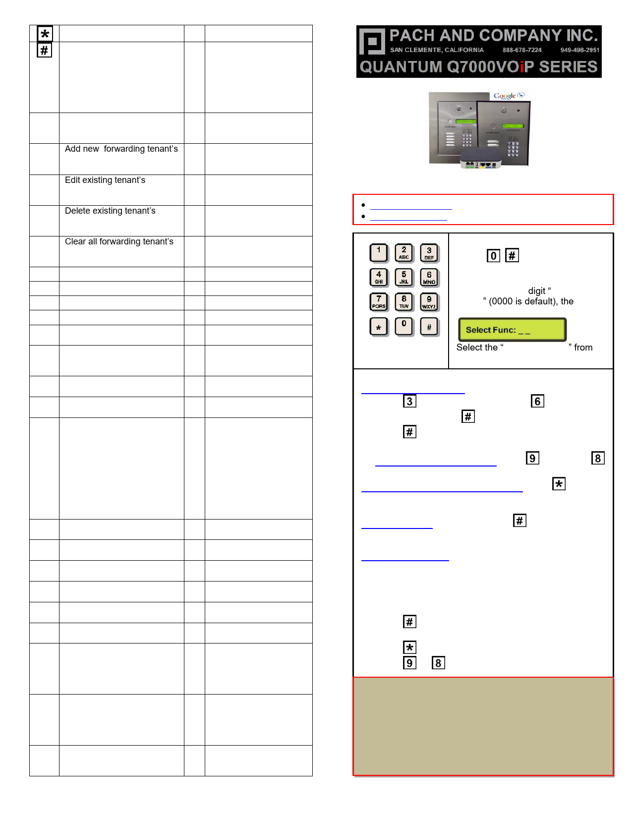
Exit program, cancel call

23 Lock-out Count

Save program

24 Alarm

0= disable

1= local beep for 60

seconds

2= disable system for 60

seconds with no beep

3= call directory (0-9)

00 Change master code (0000 25 Keypad beep

is default)

0= disable (default)

1=enable

01 Add new forwarding tenant's 26 Door beep

directory

0= disable

1= enable (default)

02 Edit existing tenant's

27 Talk time (060-240

directory

second). Default=60

second

03 Delete existing tenant's

28 Unlock relay1 time

directory

(12-99 second).

Default= 12 second

04 Clear all forwarding tenant's 29 Unlock relay2 time

directory

(12-99 second).

Default= 12 second

05 Enable/Disable Call

33 Temporary code

06 New access code

34 Special code

07 Delete access code

35 Temporary card

08 Clear all access code

36 Special card

09 Access code digit (4-8 digit). 38 System acknowledge

Default is 4-digit

(0-9). Default= 3

10 Add new card

39 Remote access

0= disable

1=enable (default)

11 Delete card

40 DTMF relay 1 (0-9).

Default=9

12 Clear all card

41 DTMF relay 2 (0-9).

Default=8

13 Set time

42 Relay 2 Mode

1= door control (default)

2= relay 2 trigger

simultaneously as relay

1

3= enable if function

code 24 is enable

4= turn relay 2 on and

off

On=7, Off=6

14 Set date

43 DND: do not disturb time

zone (0-9)

15 Initializing event recording

44 Disable Time zone relay

1, 2 or both

16 AUS= auto unlock schedule 45 Relay 1 and 2 unlock

(0-9 schedule)

timer

17 TMZ= time zone. 20 TMZ,

46 Firmware version

00-20.

18 HLD= holiday zone. 20 HLD, 48 PBX enable. Default=

1-20

disable

19 Directory digit (2-4 digit).

49 Edit Access code

Default is 2-digit

20 AUXIN1

50 Erase the memory to

0= disable (default)

factory default

1= enable control by relay 1

open interval

2= relay 1 control by AuxIn2

21 AUXIN2

51 Welcome screen

0= disable (default)

1= enable control by relay 2

open interval

2= relay 2 control by AuxIn2

22 Do not disturb

0= disable (default),

1= enable

Google Logo is registered trademarks of Google Inc.

· 24 Months warranty for complete system · 6 Months warranty for Printed Circuit Board

Log on to programming:

Press

simultaneously then

release, the welcome message will

stop scrolling (repeat if screen still

scrolling) enter 4-digit "MASTER

CODE" (0000 is default), the screen

will show as below:

Select the "Function Code" from the table

OPERATION Two ways to call tenant

1. Press to scroll name from A-Z or to scroll name

from Z-A then press to call name selected.

2. Press wait for dial tone then press the directory number

Opening the door remotely press (relay 2)

(relay 1) or

Open the door with the access code press (display screen will stop scrolling) then press a valid 4-digit access code.

Extend talk time tenant must press after the time out warning beep.

from the phone

Call into the system: 1. Enable function code 39 and function code 38 must be
set 1-9 2. Call the system phone number, hear one beep if the
system answering the call.

3. Press beep

then 4-digit master code, hear one short

4. Press to establish two way communication

5. Press or to release the door. . QWCM iP BROWSER DEFAULT IP IP: 192.168.1.230 SUBNET: 255.255.255.0 GATEWAY: 192.168.1.1 DNS: 192.168.1.1 USERNAME: Administrator PASSWORD: 8888 / pach

1. INPUT POWER 12VAC 40VA SUPPLIED (voltage measurement must be (12.5-14.0 VAC) OR 12VDC 2A adjustable power supply (voltage measurement must be 13.5-14.0 VDC)

2. 12 VDC 4Ahr BATTERY BACK-UP (OPTIONAL) WARNING: THIS IS NOT INPUT POWER

3. DOOR 2 DRY CONTACT RELAY, MUST USE SEPARATE POWER FOR DOOR STRIKE

4. DOOR 1 DRY CONTACT RELAY, MUST USE SEPARATE POWER FOR DOOR STRIKE

5. TELEPHONE OUT LOOP TO NEXT QC SYSTEM, IF TELEPHONE LINE IS SHARED

6. TELEPHONE INPUT ANALOG DIAL TONE "ONLY"

7. AUX 1 AND AUX 2 FOR EXIT SWITCH, LOOP DETECTOR OR ANY INPUT DEVICE WITH DRY CONTACT OUTPUT.

8. DOORS1 AND DOORS 2 SENSOR. WARNING: THESE ARE NOT DOOR CONTACTS

9. RS-485 PORT, CONNECT TO SLAVE UNITS (USCR, UCRM, USKP AND USKPR) UP TO 8 UNITS

10. 26-WIEGAND INPUT. PROPRIETARY CARD READER IS BUILT-IN ON THE QC SERIES. DISCONNECT THE BUILT-IN READER IF YOU ARE USING YOUR OWN CARD READER.

11. FACTORY USE "ONLY" TO POWER THE QWCM IP MODULE AND FAN. WARNING: "DO NOT USE THE +12VDC POWER TO POWER ANY OTHER DEVICES".

12. QATA2 INPUT POWER 12 VDC (SUPPLIED)

Technical Support is available Monday-Friday 7:00 am-4:00 pm PST at 1-888-678-7224

13. QATA2 INTERNET CONNECT TO ROUTER OR SWITCH

Technical Info and complete manual are available online

14. QATA2 LAN CONNECT TO QWCM (#17)

www.pach-co.com

15. QATA2 PHONE 1 ANALOG DIAL TONE (FREE ACTIVATION IS REQUIRED) CONNECT TO (#6)

16. QWCM POWER AND COMMUNICATION CONNECT TO (#11 12VDC POWER) AND (#18 RS-232). DO NOT UPLUG THIS CONNECTOR WITH POWER ON FACTORY PREWIRED

17. QWCM ETHERNET PORT CONECT TO (#14 on QATA2)

QATA2 GOOGLE VOICE ACTIVATION CALL 1-888-678-7224

18. RS-232 CONNECT TO (#16 ON QWCM) FACTORY PREWIRED

GOOGLE VOICE SERVICE IS FREE WITHIN USA AND CANADA
Microsoft Word for Microsoft 365