HOLTEN 807249 Laminair Elevation Stand 2010 Cabinet Instruction Manual
File info: application/pdf · 15 pages · 870.17KB
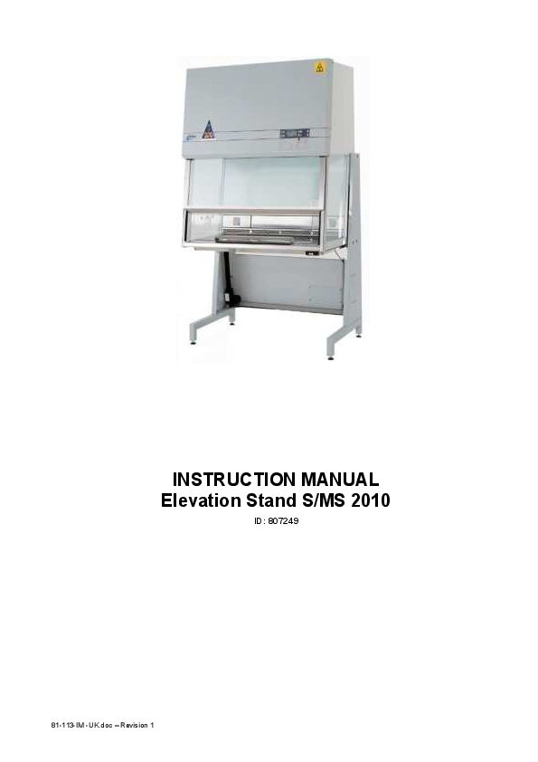
INSTRUCTION MANUAL Elevation Stand S/MS 2010 - Frank's ...
The warranty included in the conditions of delivery is valid only if the product has been installed and used in accordance with the instructions supplied by Jouan.
Extracted Text
INSTRUCTION MANUAL Elevation Stand S/MS 2010
ID: 807249
81-113-IM -UK.doc � Revision 1

Side 2 / 14

INSTRUCTION MANUAL

Elevation Stand S/MS 2010

Important user information
Please read this entire manual to fully understand the safe and effective use of this product.
In case you have any comments about this manual we will appreciate receiving them at the address below.

Warranty and Liability
Jouan Nordic A/S guaranties that the product delivered has been thoroughly tested to ensure that it meets its published specifications. The warranty included in the conditions of delivery is valid only if the product has been installed and used in accordance with the instructions supplied by Jouan Nordic A/S.
Jouan Nordic A/S shall in no event be liable for incidental or consequential damages, including without limitation, lost profits, loss of income, loss of business opportunities, loss of use, and other related exposures, caused by e.g. incorrect use of the product.

Symbols used in this manual

WARNING Used in case of danger of a serious accident or when documentation needs to be consulted.

.

NOTE Used to direct attention to a special item.

� Copyright 2003

Jouan Nordic A/S Gydevang 17-19 DK-3450 Aller�d Denmark

Telephone +45 48 16 62 00

Fax

+45 48 16 62 97

e-mail

info@jouannordic.com

Home page: http://www.jouannordic.com

81-113-IM -UK.doc

Elevation Stand S/MS 2010

INSTRUCTION MANUAL
Table of contents

Side 3 / 14

1. 2. 3. 3.1. 3.2. 3.3. 4. 4.1. 4.1.1. 4.1.2. 4.1.3. 4.1.4. 4.1.5. 4.1.6. 4.1.7. 4.2. 4.2.1. 4.2.2. 4.3. 5. 6. 6.1. 7.

Introduction ...................................................................................................4 Safety precautions ........................................................................................4 Description and technical specifications.....................................................4 Design .............................................................................................................4 Property of materials .......................................................................................5 Technical specifications...................................................................................6 Installation .....................................................................................................7 Assembling ...................................................................................................... 7 Assembling gable stands on the cabinet..........................................................7 Assembling the actuators ................................................................................8 Assembling the strengthening plates ...............................................................9 Assembling the lock sheet ...............................................................................9 Dismounting securing screws (important) ......................................................10 Assembling the rear plate ..............................................................................11 Assembling control panel and wires ..............................................................11 Transport through passage narrower than 900 mm .......................................12 Safe 2010......................................................................................................12 Maxi Safe 2010 .............................................................................................12 Preparations before use ................................................................................12 Control panel ...............................................................................................13 Maintenance................................................................................................. 13 Replacement of actuators..............................................................................13 Spare parts...................................................................................................14

Enclosure: Declaration of conformity

81-113-IM -UK.doc

Side 4 / 14

INSTRUCTION MANUAL

Elevation Stand S/MS 2010

1. Introduction
You are now in possession of a high quality Elevation Stand S/MS 2010, which is an option for the Holten Safe 2010 / Maxi Safe 2010 cabinets. The Elevation Stand S/MS 2010 applies the Safe and Maxi Safe cabinets as well, the only variations is the length of the rear plate.

The Elevation Stand complies with the General requirements stipulated in The Safety of machinery (EN 60204-1:1999), the Low voltage directive and the Electromagnetic comparability directive, and consequently CE-labelled. Furthermore the Elevation Stand meets the requirements stated in EN 12469:2000.

The Elevation Stand guarantees an accurate and individual working height in an working environment with more users, and at the same time each individual has the opportunity to alternate working posture between sitting or standing at the bench.
2. Safety precautions

� To avoid improper and unintended operation of the Elevation Stand it is recommended that
the user read this manual thoroughly.

� Also please pay attention to the Instruction manual for the cabinet.

WARNING The 120 kg maximum allowable weight in the cabinet must not be exceeded.

WARNING Newer place objects above or under the cabinet, otherwise there is danger of squeezing the object or tilting the cabinet.
WARNING When the elevation stand is activated the user shall pay attention to the fact that no person keep their hands or other parts of the body in the near of the movable cabinet.
3. Description and technical specifications

3.1. Design The Elevation Stand for the Holten SAFE 2010/MAXI SAFE 2010 Class II cabinets consists of:
� High technical electric linear actuator system with control box and control panel. � Quality linear control. � A pair of gable stands, which harmonise with the rest of the cabinet design. � Rear plate and strengthening plates, which help to secure stability.

81-113-IM -UK.doc

Elevation Stand S/MS 2010
3.2. Property of materials
Units Telescopic rail
Gable Rear plate
Foot Actuator � piston rod
Actuator � cabinet

INSTRUCTION MANUAL
Material Ball-bearing steel Electroplated steel DC 01 AM / EN 10130 DC 01 AM / EN 10130
Stainless steel Glass fibre

Side 5 / 14
Treatment Polyester coated Polyester coated Polyester coated

700 mm
Safe 1.2 showing the Elevation Stand in floor position. Table height 700 mm � 20 mm.

81-113-IM -UK.doc

Side 6 / 14

INSTRUCTION MANUAL

Elevation Stand S/MS 2010

1000 mm

Safe 1.2 Elevation Stand in top position. Table height 1000 mm � 20 mm.

3.3. Technical specifications
Elevation stand for SAFE/MAXI SAFE 2010
Width Depth Minimum table height Maximum table height Maximum cabinet height with out additional exhaust equipment Maximum ceiling height Migration Weight Maximum load of the table top Rate/velocity Supply Voltage/frequency Maximum Power consumption Maximum Current consumption Required fusing
Life time

Model 0.9 1036 mm
-

Model 1.2

Model 1.5

1336 mm

1636 mm

795 mm

700 � 20 mm

1000 � 20 mm

2250 mm

2500 mm

300 mm

-

-

120 kg

5.0 � 9.0 mm/s

230 V AC � 10 %, 50 Hz

700 W

3 A

10 A

10000 cycles

Model 1.8 1936 mm
-

81-113-IM -UK.doc

Elevation Stand S/MS 2010
4. Installation

INSTRUCTION MANUAL

Side 7 / 14

4.1. Assembling
When buying the Elevation Stand separately as an option for a domestic bench, the mounting instructions in this manual has to be followed. If buying a new cabinet, the new cabinet comes with the Elevation Stand.
4.1.1. Assembling gable stands on the cabinet
1. The gable stands are mounted with three countersunk M8 screws on each side og te bench.
2. To cover the screw hole stands fit the holes on each side of the cabinet with three black stoppers.

81-113-IM -UK.doc

Side 8 / 14

INSTRUCTION MANUAL

4.1.2. Assembling the actuators

Elevation Stand S/MS 2010

1. Connect the table switch to the control box.
� The actuators are connected to the control box to port one and two respectively. � The control box is connected to the power switch.

2. Keep the strengthening plates to the gable stands in each side.

3. Install the actuators in the rail on the gable stands.

4. Tilt the actuators forward, both pointing 5. Run the actuators backward in order to

towards the rail on the carrying plates.

secure parallel operation and

subsequently forward, until they are

placed in the rail on the carrying plates.

Avoid that the spindles revolve.

81-113-IM -UK.doc

Elevation Stand S/MS 2010

INSTRUCTION MANUAL

4.1.3. Assembling the strengthening plates

Side 9 / 14

1. Pull the strengthening plates in both 2. Mount two M6-cheese head screws with

sides of the bench backwards.

washers in both sides of the bench.

4.1.4. Assembling the lock sheet

1. Push the striking plates in between the actuators and the carrying plates. 2. The two striking plates are griped with two M6-cheese head screws and washers.
81-113-IM -UK.doc

Side 10 / 14

INSTRUCTION MANUAL

4.1.5. Dismounting securing screws (important)

Elevation Stand S/MS 2010

1. Dismount the securing screws with 2. Place the securing screws with washers in

washers from the oval hole in the carrying

the hole at the rear side of the gable

plates.

stands.

3. Before assembling the securing screws, see that the cabinet is placed correctly in the right height so that the thread hole appears behind the oval hole in the carrying plates.
81-113-IM -UK.doc

Elevation Stand S/MS 2010

INSTRUCTION MANUAL

4.1.6. Assembling the rear plate

Side 11 / 14

1. The rear plate is installed on the gable stands with five M4 pan head machine screws on each side.
2. Secure the strengthening plates, each plate with two M5 pan head machine screws with not, by means of which the long cable rail is installed as well (see section 4.1.7).
4.1.7. Assembling control panel and wires

1. Run the wire for the table switch following the edge on the trough and fasten the wire with strips so that the wire don't incur damage or squeezing when the Elevation Stand is running up/down.
2. The sustain-plate is fastening with two M4 pan head machine screws and subsequently the table switch is installed on the sustain-plate with two M3 pan head machine screws.
81-113-IM -UK.doc

Side 12 / 14

INSTRUCTION MANUAL

Elevation Stand S/MS 2010

3. As shown cable rails hide the wires. The long cable rail is installed on the four pan head machine screws, which keep the strengthening plates to the rear plate. The short cable rail is pasted on the rear plate.
4.2. Transport through passage narrower than 900 mm
When buying the Elevation Stand together with a new cabinet, it can be necessary to tilt the cabinet 10 � if the cabinet has to be transported through a passageway that is narrower than 900 mm. 4.2.1.Safe 2010
In terms of a Safe 2010 cabinet and a passageway < 900 mm the instructions in section 4.1.1 to 4.1.6 in this manual has to be followed in reversed order. Hereafter refers to section 6.1 in the Instruction manual for Safe / Maxi Safe 2010.
4.2.2.Maxi Safe 2010
When tilting a Maxi Safe 2010 with Elevation Stand, the actuators has to be dismounted at the top connection while the securing screws are mounted as described in section 4.1.5. When the actuators are dismounted they have to be lowered in order to give space for the cabinet to tilt. Tilt the Safe 2010 following section 6.1 in the Instruction manual for Safe 2010/Maxi Safe 2010.
4.3. Preparations before use Checking list
WARNING Before applications make sure that the securing screws from the transport of the cabinet is removed.
� Connect the Elevation Stand to the socket (~ 230 V).
� Pull down the cabinet until bottom position in order to make sure that the actuators run
parallel.
81-113-IM -UK.doc

Elevation Stand S/MS 2010

INSTRUCTION MANUAL

Side 13 / 14

� Make sure that the bench is stable on all four feet and that the cabinet is in level.

� Check that all external connections are flexible.

� Inspect that no mains wire or other connections to the cabinet are being stretched.

� Run the cabinet to top position in order to make sure that the cabinet can run freely from
bottom to top position. Minimum height to the ceiling is 2.5 m counting for a cabinet without extra equipment mounted on top.
5. Control panel

Operation Keep pushing the arrow button to the wanted altitude has been reached.
Keys:
 Moving up  Moving down 6. Maintenance

6.1. Replacement of actuators
The actuator carries a 10000 strokes guarantee. The system with one actuator in each side of the bench will prevent it from collapsing in case one actuator gets worn out. The user will in case of abrasion have the possibility to run the cabinet downward at the bottom-position.

.

NOTE Avoid if possible to run the cabinet right down to the floor, it will easier the replacement of the actuators. The mounting of the actuators is carried out in reverse order.

The actuators are replaced by following the instructions for dismounting the old actuators in the mounting guidance in section 4.1.6 to 4.1.2. Installation of the new actuators is done in reverse order.

.

NOTE If the cabinet is in floor position it is not possible to mount the regulating screws and furthermore the actuators can not run free of the carrying plates. Therefore the steps are as follows:

1. The bench is lifted up 50 mm, by adjusting the regulating screws on the stand feet.
81-113-IM -UK.doc

Side 14 / 14

INSTRUCTION MANUAL

Elevation Stand S/MS 2010

2. Support the cabinet in this position.

3. Loosen and free the actuators by using the regulating screws at the stand to lower gable stands.

4. Mount the new actuators in reverse order.

7. Spare parts
Components Electric actuator Controller box for actuator Keyboard for actuator

Jouan Nordic No. 86004514 86004515 86004516

81-113-IM -UK.doc