For all two-way radio enthusiasts

Jan

AMATEUR RADIO: UK Ham Radio and Two-Way radio periodical

Amateur-Radio-1985-01
JANUARY 1985 99p
For all two-way radio enthusiasts
toe
batOed Weed lbeieete oiNtsb09 toes ea tectiettes
%tee On test: 13cm equipment

R WITHERS
COMMUNICATIONS

le AUTH'OR[I-SYED YAESU w

584 HAGLEY ROAD WEST, OLDBURY, WARLEY B68 OBS (QUINTON, BIRMINGHAM) WEST MIDS.' Tel: 021-421 8201/2 ( 24 HR ANSWERPHONE

A ·s
RWC SPECIAL OFFER

PLEASE ASK ABOUT THE RWC CREDITCARD AVAILABLE NOW VIA LOMBARD TRICITY

R.W.C.'S BARGAIN WINDOWS ONCE ONLY OFFERS

RWC NEW 1985 RANGE OF LINEAR AMPS FOR UHF &
VHF SEND SAE
FOR FULL INFO

YAESU FT29OR FREE · HB9CV £299 · VARTA
NI- CADS ·CHARGER ·LISTEN ON INPUT
WHILE STOCKS
LAST
10 MTR MOD KIT FOR DNT 40FM AND LCL2740
INC 2x-TALS
RWC lx-TALFILTER BEST 2CAPACITORS
SELLER £12.95

SPECIAL
'8 VARTA C SIZE NI-CADS
1200MaH ONLY
£17.50

4e!STANDARD VHF FM MAR BATTERY OR 12V. 4- CH 140-172MHZ WITH CIRCUIT 9 ONLY C65

YAESU FT708R
FREE HBOCV
411I-CADS *CASE clog *CHARGER 10 ONLY*POST Bic LAST FIVE AT THIS PRICE

AM+ FM

'R.W.C. Special' Revco RS 2000 Ext Coverage 60-179 & 380-520MHz

£219.00

THIS PRICE *70 MEMORIES
"AC-DC SUPPLY *AUTO SEARCH *LOCK PRIORITY

LCL 1011Tre MOBILE LAST
*TEN '6W '40CM ·INC BRAC-
KET £47.50

Professional 4channel 27MHz hand helds inc case & batteries. Superb quality easily

CENTURY 21D

wrop PRESS ... STOP PRESS ... STOP PRESS...

RWC MOD KIT FOR LC 71367 CHIPS ( IE MOST CB RIGS) WILL

LAST

FREE G5 RV MULTIBAND ANT '500Kc's-30 MHZ

BE AVAILABLE FROM THE 1ST DECEMBER 1984. IT WILL MODIFY ANY CB RADIO WITH THE ABOVE PLL CHIP UP TO AND BEYOND 30MHz. IN 400KHz, 40 CHANNEL STEPS. THE

THREE

·BARLOWWADLEY LOOP

UNIT HAS BUILT IN 10 METRE REPEATER OFFSET AND HAS

£198 · POST FREE
AM+ SS3

·LED DISPLAY ·HEADPHONE JACK

ONLY EIGHT WIRES TO SOLDER INTO THE EXISTING RADIO WITH READJUSTMENTS ON VCO, RX, RF AND TX RF. PRICE PROVISIONALLY f22.50 FOR BUILT AND TESTED PCB AND FULL INSTRUCTIONS

HITACHI 9" SECONDHAND
MONITORS. SEVERAL TYPES TO CHOOSE FROM
ONLY £45 ea.

convts to 10 Mtrs. Fantastic value only £34.95

FARRELL 10 AMP OK ON 218TU
PSU REGULATED AND FULLY PROTECTED SWITCH ( LIST £185) MODE LAST FEW £39.50

AKD WAVE METER. A MUST
FOR ALL VHF STATIONS
£24.95 inc p

TURN THAT BEAM KOPEK ROTATORS
50KG LOADING
FULL 1YEAR WARRANTY ACCURATE TO 1° £37

RWC'S HB9CV 2Mtrs £6.99. 70Cms £5.99
post & pck £1.00.

e POWER

e

MODULES FOR FDK

firgi YAESU

ICOM TRIO

ETC. EG 25W 2MTRE

WRITE FOR

FULL LIST,

FROM £35.00

BARGAIN
ONE ONLY
COMPUTOR ROTATOR CT1000
1/2 PRICE £299

SUN TRIPLE eita BASE ANTENNA
144-148MHZ
7.2DB1 QUALITY
CONSTRUCTION LOW VSWR
SAVE £es £29.95

3 0"

HOXIN DC GROUND

1/2 WAVE MOBILE

INC ANT

PL259

+CO- AX £9.50

TO CLEAR ·

TRAVELLING EM
2M 70CMS INC LEAD 2M £7.95 + PL259 70CM £6.95

R.W.C. BARGAIN

PACK

be!

BNC KIT SILVER + NICKEL

PLATED

ELBOWS WORTH VIO PLUGS ETC ONLY £5.99

POUCE BAND 1/4 WAVE
FINE ON 2MTRE

LAST FEW INC WITTE BASE SILLY PRICE £4.50

USA MADE

PUSH ON PL259

LAST
300 TO CLEAR

uFOR UR67 UR43

99p FOR THREE ,

SUN HIGH QUALITY
GUTTER MOUNT KITS INC 4Mtrs CO-AX AND
PL 259 ANODISED

l ie

BLACK FINISH
ONLY £9.95

SILVER PLATED 'N' TYPE

TWO WAY

2KW CO-AX SWITCH LESS THAN 1dB LOSS 14 ONLY
£13.50

STOP PRESS LOW PASS TVI

13.5RV HF MULTI- BAND" DIPOLE ANTENNA

FILTER BY TELCO LIST £39.95

FULL - 1/ 2 SIZE SIZE £ 12.95 £14.95

12 ONLY £12.50

MADE IN USA

POST 8. PACKIG FREE!

aHF AERIAL TRAPS W3OZZ TYPE HIGH

CCTV LENS 4110 39MM JAP

QUALITY 7.1MHZ

'C' TYPE FIXING

£8.05 PAIR POST FREE

TOKINA QUALITY WERE £30 FEW ONLY £7.50

FT102 AM FILTERS
0XF 455 CPI BY YAESU ALSO A FEW CW FILTERS
£19.50

RF TRANSISTORS OVER 20,000W IN STOCK FOR ALL
HFNHF/UHF RADIOS
EG.
2SC 1947 £7.50 2SC 2290 là £24.00

VERY HEAVY CHROME PLATE
MORSE KEY
BLOCK SUIT
HK705 ETC. WITH FREE 1/4"
JACK + LEAD £6.95

MINI HEADPHONES
3.5MM - 1/e,JACKS

MONO

f STEREO

SUPER .QUALITY

LIGHTWEIGHT DESIGN

£3.95 INC P&P

quip KENWOOD TRIO
NOISE CANCELLING DMIYKNEAMIC

SUPER

QUALITY

LAST

£12.50

FIVE

HEAVY DUTY

MAGNETIC MOUNT

S0239 MOUNT

3M COAX +

PL259 SPECIAL

:11111111P

PRICE £8.95

All offers subject to availability on afirst come first served basis. Prices subject to change without notice, all correct at time of going to press, E&OE. TERMS: No COD. Barclaycard and Access accepted. Post free over £50, under £50 add £2 post and handling, unless stated. Please send SAE with all enquiries and for latest secondhand list.

6 Letters Your opinions on topics of interest
8Straight and Level All the latest news, comment and developments on the amateur radio scene

50 Back to basics This month Bill Mantovani G4ZVB looks at semiconductors
54 Aerials and propagation How to maximise an aerial's performance

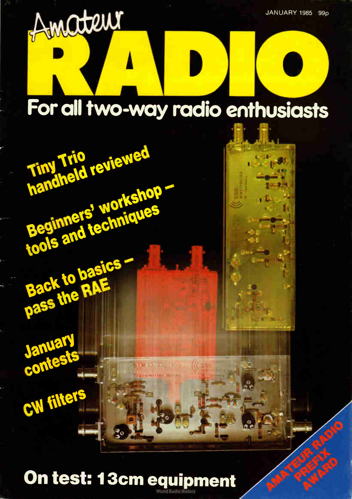
Editor: Jim Chalmers Editorial Assistant: Anita Ley Advertisement Manager Anne Brady Subscriptions: 01-684 3157 Accounts: Clare Brinkman Publisher: Peter Williams General Manager: Alan Golbourn On sale: Fourth Thursday of the month preceding cover date Next issue: Cover date February 1985 on sale 24 January 1985 Published by: Amateur Radio Magazines, Sovereign House, Brentwood, Essex CM14 4SE, England (0277 219876) Printed: In England ISSN: 0264-2557 News Trade Sales by: Argus Press Sales & Distribution Ltd, 12-18 Paul Street, London EC2A 4JS. 01-247 8233 Front COVer SSB Products 13cm equipment reviewed this month ( p15). Photo by Jay Moss- Powell G6X1B
Whilst every care is taken when accepting advertisements we cannot accept responsibility for unsatisfactory transactions. We will, however, thoroughly investigate any complaints. The views expressed by contributors are not necessarily those of the publishers. Every care is also taken to ensure that the contents of Amateur Radio are accurate, we assume no responsibility for any effect from errors or omissions.
Audit Bureau of Circulations membership applied for © Copyright 1984
Amateur Radio Magazines

12 DX Diary Don Field G3XTT with this month's DX news
15 Angus McKenzie tests This month G3OSS looks at getting started on 13cm and the new Trio TH -21E handheld
24 January contests Nigel Cawthorne G3TXF looks at the contests open to operators in January, along with news from France
27 Beginners' workshop Rev George Dobbs G3RJV commences aseries of articles for the would-be constructor
3211154/R1155 Another look at this wartime installation
37 SWL Trevor Morgan GW4OXB looks at the contents of his mail box, and if you think that's all, read on ...
40 CW reception Peter Dodson with two technical aids for the home constructor who wants to go ' beep'
44 On the beam Glen Ross G8MWR with all the latest news from VHF, UHF and microwaves
46 CB conversions A look at the MC145106 chip and modifications for ten metre amateur use

56 Coming next month What's in store for you
58 Among my souvenirs: Old Ham looks at the Marconi V2A that was rescued from adusty loft 60 Secondhand Hugh Allison G3XSE shares his knowledge in repairing radiorelated equipment 62 Free Classified Ads The market for buying and selling
SERVICES
36 Amateurs Handbook order form 42 Newsagents order form 61 Subscription order form 63 Free Classified Ad form 65 Radio and Electronics World
subscription order form 66 Advertisers Index 66 Advertising rates and information

JANUARY 1985

please mention AMATEUR RADIO when replying to any advertisement

3

LOWE SHOPS
Whenever you enter a LOWE ELECTRONICS' shop, be it Glasgow, Darlington, Cambridge, Cardiff, London or here at Matlock, then you can be certain that, along with acourteous welcome, you will receive straightforward advice. Advice given, not with the intention of " making" asale, but the sort which is given freely by one radio amateur to another. Of course, if you decide to purchase then you have the knowledge that LOWE ELECTRONICS are the company that set the standard for amateur radio shops and after- sales service. The shops are open Tuesday to Friday from 9.00 to 5.30 p.m., Saturday from 9.00 to 5.00 p.m. and close for lunch each day from 12.30 till 1.30 p.m.
In Glasgow the LOWE ELECTRONICS' shop ( the telephone number is 041-945 2626) is managed by Sim GM 3SAN. Its address is 4/5 Queen Margaret's Road, off Queen Margaret's Drive. That's the right turn off Great Western Road at the Botanical Gardens' traffic lights. Street parking is available outside the shop and afterwards the Botanical gardens are well worth avisit.
In the North East the LOWE ELECTRONICS' shop is found in the delightful market town of Darlington (the telephone number is 0325 486121) and is managed by Don G3GEA. The shop's address is 56 North Road, Darlington. That is on the A167 Durham road out of town. A huge free car park across the road, a large supermarket and bistro restaurant combine to make avisit to Darlington apleasure for the whole family.
Cambridge, not only a University town but the location of a LOWE ELECTRONICS' shop managed by Tony G4NBS. The address is 162 High Street, Chesterton, Cambridge the telephone number is 0223 311230). From the A45 just to the north of Cambridge turn off into the town on the A1039, past the science park and turn left at the first roundabout, signposted Chesterton. After passing achildren's playground on your left turn left again ( between the shops) into Green End Road. Very quickly, and without you noticing it, Green End Road becomes High Street. Easy and free street parking is available outside the Shop.
For South Wales, the LOWE ELECTRONICS' shop is located in Cardiff. Managed by Richard GW4NAD, who hails from Penarth, the shop ( the telephone number is 0222 464154) is located within the premises (on the first floor) of South Wales Carpets, Clifton Street, Cardiff. Clifton Street is easily found, being a left turn off Newport Road just before the Infirmary. Once in Clifton Street, South Wales Carpets is the modern red brick building at the end of the street on the right hand side. Enter the shop, follow the arrows past the carpets, up the stairs and the " Emporium" awaits you. Free street parking is available outside the shop.
LOWE ELECTRONICS' London shop is located at 223/225 Field End Road, Eastcote, Middlesex ( the telephone number is 01-429 3256). The shop, managed by Andy G4DHQ is easily found, being part of Eastcote tube station buildings and as such being on the Metropolitan and Piccadilly lines ( approximately 30 minutes from Baker Street main junction). For the motorist, we are only about 10 minutes' driving time from the M40, A40, North Circular Road at Hangar Lane) and the new M25 junction at Denham. Immediately behind the shop is a large car park where you can currently park for the day for 2. There is also free street parking outside the shop.
Although not ashop there is on the South Coast asource of good advice and equipment -- John G 3JYG. His address is 16 Harvard Road, Ringmer, Lewes, Sussex. ( telephone 0273 812071). An evening or weekend telephone call will put you in touch with John.
Finally, here in Matlock, David G4KFN is in charge. Located in an area of scenic beauty avisit to the shop can combine amateur radio with an outing for the whole family. May Isuggest ameal in one of the town's inexpensive restaurants or apicnic on the hill tops followed by aspell of portable operation.

For many years
Ihave found much pleasure in slowly tuning areceiver across the short wave bands. Iremember discovering that the new wireless, just purchased by my Grandfather, had on it ashort wave section. So, after the family had listened to " The Archers" and set about the evening's activities, Iwas left with the set to myself, able to tune around and listen to the world. Iam certain that the thing that fascinated me then is still the same today; the fact that transmissions from such exotic places so far away could be heard in my own surroundings. Perhaps Iam aromantic at heart but to imagine the sights and sounds of the countries originating the transmissions was special. Ifind it difficult to describe the feeling. I have since spoken to many people who have shared the same experience, they too find it difficult to explain.
Since those days
things have changed and many receivers have come and gone. When compared with the large pieces of surplus equipment once used by the short wave listener in his shed at the bottom of the garden, today's equipment looks " very HI- Fl". Most of the receivers carry the description "general coverage" meaning that it will tune without gaps frequencies from around 100 kHz to 30 MHz. Such wide coverage means that not only can you listen to amateurs and short wave broadcast stations worldwide, you can also hear Radios 1, 2, 3and 4and Laser on 588 kHz. To the short wave listener this is agreat advantage over rigs which only have selected bands. It is usually the band you particularly want that the manufacturer had decided you could do without. The receivers which Inow describe are all "general coverage", and lmight add are each capable of giving you the satisfaction which Idescribe above.
the R600
At the start of the range is the TRIO R600 which costs £85.26 Including VAT. This is the receiver for the beginner, the person of limited means or the cynic who does not really believe my enthuse. The R600 is abasic receiver covering from 150 kHz to 30 MHz and having switched upper and lower sidebands, wide and narrow am and cw. It has a 20 dB attenuator and anoise blanker fitted as standard. Operation is simple, select the mode of operation, turn the MHz dial to the correct band and, by using the VFO knob, tune to the desired frequency. The clear digital readout makes station selection simple. The TRIO R600 is an ideal receiver for shack, bedroom or lounge.

LOWE ELECTRONICS
Chesterfield Road, Matlock, Derbyshire. DE4 5LE. Telephone 0629 2817, 2430,4057, 4995. Telex 377482.

4

please mention AMATEUR RADIO when replying to any advertisement

JANUARY 1985

the R2000
Moving upward from the R600 we find the TRIO R2000. The receiver covers frequencies from 100 kHz to 30 MHz and has, in addition to the facilities found on the R600, aten channel memory to hold for quick access your favourite stations. Memory operation is versatile, each memory retaining not only the frequency but the mode of operation. Each memory can be also used as aseparate VFO. In addition to AM, USB, LSB and CW the R2000 is fitted with FM which, when used

There are amongst us adiscerning few for whom only the best is good enough. For them there is only one receiver: this is the NRD 515 manufactured by the JAPAN RADIO COMPANY. The receiver is built to professional standards and is designed to give its owner the ultimate in listening pleasure. Covering 100 kHz to 30 MHz the NRD 515 has pass band tuning, slow and fast AGC and apreselector covering the broadcast bands from 600 kHz to 1.6 MHz. Optional
accessories include a 96 channel memory unit ( NDH 518 £264,00 inc VAT), a remote frequency controller giving keyboard frequency entry, plus an additional four memories (NCM 515 £ 169.75 inc VAT) and a matching speaker (NVA515 £ 45.41 inc VAT). The NRD515 short wave monitor receiver costs £ 965.00 inc VAT.
and the AR2001....

It is rare to use apiece of equipment so refreshingly new as to
be devastating. Although it has been my pleasure to use numerous receivers over the past years nothing has so captured my attention as has the AR 2001 from the company
AOR. Authority On Radio, AOR, sums them up exactly. In the past there have been several receivers covering parts of
the HF/VHF/UHF spectrum but never before a receiver
with the VC10 internal vhf converter, enables the amateur 2 metre band to be fully listened to. Another advantage over the R600 is that the R2000 tunes continuously up the band and not in 1MHz sections. Three rates of tuning are provided enabling the band to be either searched diligently or quickly "scanned". With the optional VC10 fitted the R2000 adds to its frequency range the VHF section from 118 to 174 MHz and, of course, operates on AM, FM, USB, LSB and CW. Fast or slow AGC can also be easily selected using a front panel switch. Altogether afine receiver and ideal for today's listener. The TRIO R2000 costs £456.63 including VAT. The optional VC10 costs £ 122.26 including VAT and is easily fitted inside the receiver.

from JRC,

the NRD515

tuning continuously from 25 MHz to 550 MHz. Never before areceiver having AM, narrow band FM and wide band FM.
Never one that could be afforded by all enthusiastic listeners. The AR2001 is the new concept in receiver design
combining user friendly controls to aid listening with a carefully designed receiver that actually works. The receiver with its continuous coverage between 25 and 550 MHz enables its owner to listen to a multitude of transmission sources. The provision of three modes, AM, narrow band FM
and wide band FM are essential when one considers the variety of information that can be received. AM for the VHF/UHF airband channels, narrow band FM for amateur radio, CB and business radio and finally wide band FM for broadcast and TV sound. Digital frequency readout is
combined with visual reminders of receiver state and for night time listening the panel is illuminated. Scanning, memories, memory scan, programmable band scan are all
part of the receiver and to aid operating the memory not only remembers the frequency but the mode of operation. The AR2001 receiver costs £365.00 Inc. VAT.

LOWE ELECTRONICS
Chesterfield Road, Matlock, Derbyshire. DE4 5LE. Telephone 0629 2817, 2430, 4057, 4995. Telex 377482.

JANUARY 1985

please mention AMATEUR RADIO when replying to any advertisement

5

LETTERS

YOUNG HAM! Ihave been reading Amateur Radio since early 1983, and Imust congratulate you on an excellent magazine, which is well worth the money every month. Ibegan attending RAE lessons in September 1983, taking the twenty week course in preparation for the May RAE. Icelebrated my fourteenth birthday on the 21st ofJune this year and in August Ireceived my pass slip. Iam now licensed, but have no equipment as yet. Are there any other young hams out there? Iwould like to know if there is any software available for the Sinclair ZX81 which can transmit and receive messages ( not RTTY), using the simple interface described by Trever Morgan in the November issue. If there is not any software for this, could anyone write any for me? Iwould not know where to begin! Could someone also send me conversion details for converting the Microsoft Basic Maidenhead programme for the ZX81. John Flowers G1 HYZ, Lincolnshire
THANKS
Some time ago Iwrote to you asking for acopy of reviews on rigs such as the Yaesu 7700 standard ( and modified), Kenwood R2000 and the Icom ICR71E. The reviews have certainly helped me decide which of the above rigs not to purchase.
Ibelieve however that despite the licking' given to the Icorn by your reviewer this eventually will be the rig to be purchased. AHeinis, Melbourne
RSGB DEMOCRACY
Iread the letter RSGB Democracyfrom G3DRN with amixture of interest and amazement. The fact of the matter is that whilst the RSGB is theoretically ademocratic organization, in practice it is quite the reverse. Ihope the following will illustrate the point.
1. In any form of democratic election candidates can

publish amanifesto so that voters can decide which candidate will best represent their interests. However, the RSGB Council deny
candidates any opportunity to tell members what their views
are since only biographical details are allowed. What this
means is that, although in theory anyone who has been a member for three or more years may stand for election to the Council, there is a distinct bias in favour of
candidates who have been elected previously since these can quote all their past RSGB posts. To put it bluntly the system sone of self perpetuity. New members are not encouraged to stand for election.
2. Although the situation with the Council is bad enough the position of the
committees is much worse. The appointment of members of the committees is done by the Council who normally follow the recommendation of the committee chairman! If anyone offers to serve on any of the committees they are
inevitably vetted to see if their views are in accord with the existing committee's views. If not they are not invited to join. Note that membership is by invitation not election. A clear case of self perpetuating autocracy!
Up to three years ago the RSGB represented approximately 80% of the
amateurs in the UK. Despite the soothing tone of this year's annual report from the
General Manager as to the growth of membership, the RSGB now represents only
52% of the current licensees! In my opinion the RSGB is in
big trouble and an injection of new blood and ideas is essential if the Society is to thrive. The existing ' Old
Guard' however, strenuously resists any change with every
means at their disposal.
Ibelieve that the survival of the RSGB is vital to the amateur movement in this country. Ialso believe that it must change in order to survive. Whatever anyone may think about the current
state of amateur radio in this country, the RSGB should
represent the views of the majority; at the moment it represents the views of those

living in the past. Remember what happened to the dinosaurs who couldn't adapt to change! PL Crosland Gt3JNS, Worcester
MISLEADING
Ihave never before written this sort of letter to a magazine and Iexpect that after reading this you will just destroy it rather than printing it. However, there are Ifeel certain things that should be pointed out for the benefit of the prospective RAE candidates among us.
On the whole your magazine is informative and very readable, avery refreshing alternative to the stuffy approach of Short Wave Magazine and Practical Wireless.
But now to the rub, some of the articles that appear in your pages are, to say the least, misleading, and as a result could spoil the chances of an RAE candidate joining us on the bands.
Icall your attention to the articles of Mr Peter Dodson who, although agood writer, seems to be totally misinformed on some aspects of radio theory, and as such should not be allowed to mislead the novice.
In the November issue he has penned ablatant copy of several RSGB diagrams etc and then connected them with afew interesting observations, including the now expected slight on CB operators that many writers in the amateur radio press seem obliged to fall back on for laughs.
Mr Dodson then proceeds to expound achunk of CB folklore himself. Irefer to the old cherry that an SWR meter indicates output power, or the lack of it, which is of course a load of nonsense.
Iam not surprised at this because Mr Dodson seems very confused about the whole subject of aerials, SWR, ATUs and power. In fact in the September issue he tells us that ' ahigh SWR reading indicates lack of radiation, whilst areading as near as possible to 11 indicates the maximum transference of power'. More nonsense.

One can only assumethat Mr Dodson's technical library consists of asingle volume, 'The Big Dummies Guide to CB', as he goes on to tell us
that ' getting the aerial to resonate exactly as required
is the job of an aerial tuning unit' ( ATU). Yet more
nonsense. The next little gem is:
'beware, failure to renew an amateur licence ( cost £ 12) requires the retaking of the
entire examination'. More
nonsense still. He also informs us that the Morse test costs£18, when in fact the correct figure is£15.
Please let me put the record straight. Once passed, the RAE is like any other City & Guilds of London examination, being a qualification for life! If aB
licence holder lets his licence lapse then he has only
to re- apply and he will get his old callsign re- allocated.
If an A licence holder lets his licence lapse then he will
have to retake the Morse test, unless for some reason he
took it lessthan twelve months prior to his application.
Also, ahigh SWR in itself does not indicate lack of radiation, it only indicates an impedance mismatch between the meter and the ether, which may well have nothing to do with the aerial
but could have everything to do with an incorrect impedance of feeder. For example, a50S/ transmitter output into a501/SWR meter into some 751, 300e or 600S2
feeder and then into aperfect
SOS/ aerial would cause ahigh SWR, but the aerial could be itself aperfect match for the transmitter. However, this would not effect the actual radiation of the transmitter and aerial combination because if 100W reaches the aerial then 100W will be radiated; where else could the 100W go? The answer is of
course, nowhere. The purpose of an ATU
(better called atransmatch, because that is in fact what it
does) is to match the impedance of the aerial and
feeder combination to the
requirements of the transmitter; its sole purpose isto act as avariable
impedance transformer.

6

please mention AMATEUR RADIO when replying to any advertisement

JANUARY 1985

AMATEUR RADIO EQUIPMENT BOUGHT, SOLD 8. EXCHANGED For the best deal - Personally Guaranteed. Ring 04TNY ELECTRONICS Dave, on 025 587 663 or 040 24 57722 anytime!
Or write: 132 Albany Road, Hornchurch, Essex RM12 4AO
Is my North Essex Office NEARER you? Send SAE for our latest Ilst MAIL ORDER -- A SPECIALITY!
Used Equipment Centre
Buying or selling? Contact the Used Equipment Centre for the best deal. 25 years of amateur radio experience, friendly advice, full no quibble guarantee on all equipment. Heard about our exchange plan, buy & try? Why not contact me, David Cole G3RCO Hornchurch 55733, evenings/weekends or send SAE for full details & current list of equipment. G3RCO 65, Cecil Avenue, Hornchurch, Essex. Urgent daytime enquiries 01 -594-3495.

Q8L Cards
Printed on white or colour gloss cards, printed to
your own design. Please send SAE for sample to:
Caswell Press 21 Hornethorpe Ave, RedhIII, Surrey
Tel: ( RedhIII) 71023

EUIROLJEC VIDEO SERVICES

Tie 01 Mie11611

Telex: 893810 Eurlece

is

Add ress eàzoiguicz, i ezîu;,,,y,......,

N1700 LMrerg Cemsetlee

Studio colour cameras - please

New unused, some opened and enquire erasedwithlibrary labels removed JVC UHF urnatic tuners, new

LVC120C1OLVC913 C7.50 LVC601:5 £76.00 IsseranebweeLvecaseestas ZEIMART 3port telecine unit with

LVC9df8 50

LVC60f6 50 electronic dichroic filter unit

1600= Caneettee £E00.00

riled

2Ikegarni 3e studio cameras MO

VC60f6

VC45f5 each. complete but no decoders

VC30f4

VC15f2.50 Sony DXC 1200P. studio colour

Second used

camera with 6-1 20301 lens 6

Edit equipment currentlyavarlable. viewfo nderf.1711. VAT

* nVyh2eeatia d.,u.C editsuite .... f3,500 NTSC - PAL Transfers, phone for

MOOD

details

Sony2850suite . El.950(plusVAT)

VATReg No 335709645

0 V/ MORSE KEYS
4 Owen Close, Rhyl, Clwyd Wales Lila 2LO

TIM OW MOM KEY A ley to use and to look at, this key is made from solid brass polished and mounted on a slate base here in OW land ( net JA)
Mounting the key on slate stops all movement Of the key when in use £34 50 pp £200 ea.

24 IS LCD CLOCK Clear 1/2"high lcd readout repeat alarm clock. battery powered ( 2 AA pencells). No R/F problems known. Complete with batteries

£9 50 per £050 ea

OR

PRODUCTS

The full range of Gwhips always in stock for quick and prompt

delivery or collection.

NEW
NEW NEW

NEW EA« STATION ANTENNA FROM
OWNIP PRODUCTS AVAILABLE SOON

NEW
NEW NEW

Fer WM Mennen« end price Ilet pewee bend SAE
EMUS CALI. PLATE Your callsign engraved on abrass plate for fixing to the OW morse key or any of your radio equipment Cl 00 only
NO POST à PACIONO CHARGE FOR ORDERS OVEN £ 30.00

ALPHA KEYS
Precision engineered keys for the connoisseur. Twin or single paddle keys individually made to be one of the smoothest and lightest movements ever. For the fast operator.
CAVITY wavErria One wavemeter to cover 144MHz to over 2500MHz. Can measure RF as low as 50 Milliwatts with suitable meter. Also now short version to cover 430MHz to over 2500MHz.
10011x WAVEMETEFI KIT
A pre machined cavity to make a 10GHz wavemeter using your micrometer. Can be fixed direct to your wave guide.
COAXIAL RELAY KITS The cavity block is pre machined to take your BNC or N type sockets.
Send large SAE for full information to:
PAUL SERGENT G4ONF 6 GURNEY CLOSE COSTESSEY NORWICH NR5 CHB
Tel: (0603) 747782

A

Armstrong Kirkwood Developments

10 Willow Green Grahame Park Estate London NW9 Tel 01 205 4704

VHF/UHF ABSORPTION WAVEMETER

Covers 120-450 MHz Extremely sensitive Low- profile Re

quires PP3 battery

124.95

HIGH PERFORMANCE RF FILTERS

SLIMLINE ATTRACTIVE APPEARANCE

Us.dbyB riliahlel.c ore,Thore-EMI,ITt,T efafssioe,Gr seada etc

Standard range ternsnated in Belling Lee plug/socket

175ohms) - others to order

Model INF2 Tuned Notch Filters IBraid & Inner) for 2, 10, 15,

20 Metres & CB Istate which)

ET 50

The TNF2 range have avery low insertion loss and very high reiection over the band for which they are supplied They are the best possible answer for aerial borne interference horn a single known frequency or frequency band

Model RBFI-70cms Notch Filter Ironer only)

£6.32

Model BEll Braid Breaker £6.32 Also available. 3High Pass models and a "Radar Blip" filter for

VCRs Please send A4 or C4 stamped addressed envelope for

filters data sheet and price list

All items are manufactured by AID in UK and carry atwo year

guarantee plus 14 day money back promise no reason required)

Items usually despatched within two days from receipt of

order Pores include VAT, postage & packing

(Prop.) J.W ARMSTRONG

ALSO AVAILABLE FROM MOST LEADING AMATEUR RADIO DEALERS

THE PERFECT COMPLEMENT TO AMATEUR RADIO

Packed with construction projects and the latest technology plus pages of readers' classified ads

Take out aPOST. FREE (UK) sub while otter lasts · Delivery to your door by
publication date each month · Inflation proof - price guaranteed
for 12 months

On sale NOW at your newsagent and at equipment dealers

RADIO & ELECTRONICS WORLD SUBSCRIPTION ORDER FORM -1

To: Subscription Department · Radio & Electronics

World · 513 London Road · Thornton Heath ·

Surrey · CR4 6AR.

Tel: 01-684 3157

NAME ADDRESS

Postcode

PLEASE SUPPLY: (tick box) for 12 Issues, all rates Include P L P

Inland £11 80

World-Surface

Europe-Alr

E £ 13 10

E £19.20

World-Air

E £25.90

El

PAYMENT

······

ENCLOSED:

Cheques should be made payable to Radio & Electronics World Overseas payment by International Money Order, or
credit card

CREDIT CARD PAYMENT
I Signature

AR0185

JANUARY 1985

please mention AMATEUR RADIO when replying to any advertisement

65

LETTERS

This little box of tricks has no effect on the resonance of the aerial, how can it? It is usually some 20 to 80ft away from the aerial and only connected by alength of
fixed impedance feeder. The only way to correctly
resonate an aerial is to do what Mr Dodson tells us the CB type does ( obviously they are not that worthy of scorn); that is to make the aerial slightly oversize and trim the elements into resonance.
Surely this is the procedure
that amateurs have been using for generations? The only difference being that the ham of yesteryear would have probably used agrid dip oscillator ( GDO) rather than an SWR meter, and su prise suprise, you still can today. It's just that an SWR meter is,
for most of the time, alot more convenient.
The real reason for the upsurge in the use of SWR meters is because the solid state or transistorised transmitter of today is alot more load or output
impedance conscious than the valve output rigs of yesteryear. Most solid-state rigs today have inbuilt SWR protection, shutting down the power output when badly mismatched into ahigh SWR load which differs greatly from the designed output
impedance. Some rigs are better than others and can stand ashort circuit or open circuit for up to approx 5 minutes, but there is apenalty to be paid for such good protection.
When arig is treated to such amismatch it has to dissipate
all the power as heat, so on alot of well protected transmitters we find that an SWR of 1.5:1 will cut the output by 25 to 50%.
This is probably where the fallacy about high SWR meaning loss of power
originated. As we can see there is only just agrain of
truth in it, the rest is down to ignorance.
Still not convinced? Well, let us take an example, a transistorised 28M Hz rig running into a14MHz dipole,
ie transmitter impedance 50i),
coax impedance 50f1, dipole impedance many hundreds of
ohms, and yet the 14MHz half wave dipole is in fact

resonant at 28MHz as afull wave dipole. Result: very high SWR, the Tx shuts down and eventually blows up!
We could insert an SWR
meter at the Tx end of the feeder and trim the aerial into
resonance but the dipole would then be useless at 14MHz, so what can we do? Simple, insert atransmatch in between the SWR meter and the feeder. Then, by tuning the transmatch up we present the transmitter with aperfect 50f1 load, resulting in
maximum power output. There is still every high SWR on the feeder, but this will not
affect the radiated power. There is just one problem, a
high SWR on acoaxial feeder will be likely to cause TVI as a
coaxial cable is unbalanced and will radiate when
mismatched. The answer to this is not to use abalun transformer at the aerial feedpoint because there would still be ahigh SWR on the feeder, and it would still radiate. To prevent feeder radiation at all SWR levels
just use atransformer coupled transmatch with balanced feeder; there will then be no actual dc connection between the rig and the aerial and any length of dipole can be used on any band provided the transmatch is able to cope with the mismatch.
Result? Maximum power, plus no TVI and yet apossible high SWR. Ihope that this will clear up the matter for the RAE hopefuls, and anyone else who has in the past been confused by the folklore of the magic SWR meter.
Why don't you print Peter Dodson's callsign? Or hasn't
he got one? If he has not then how is he qualified to write on the subject of amateur radio? Perhaps he is a telecommunications engineer? But then again perhaps not.
It might be agood policy to
only print the work of licensed amateurs who will let you quote their callsigns, and also the work of people who are professionally qualified in the field of radio transmission and reception.
Many thanks for an
otherwise dynamic magazine.
Lance Whitelegg G1DJV, Bristol

Peter Dodson replies: First let me respond to the
criticisms on my article in the November issue dealing with test circuits.
There was never the slightest intention of
presenting my choice as original-- in fact the editorial staff went to considerable lengths to obtain permission to reprint the circuits in the magazine.
If Mr Whitelegg would look
again at the article he will see that Ihave use the words 0773'reproduced courtesy of the RSGB from whose publications they have been blatently filched!' Their reproduction was intended, along with those of other
authors, to offer aselection of useful tools to the amateur radio fraternity.
Furthermore, Ido not consider my remarks about 'breakers' to be in the slightest way offensive and I suspect that it was my reference to CB that touched anerve. CB is more
elementary and (for want of a better word) casual than
amateur radio, it is inadequate by comparison and many breakers have
transferred their allegiance to amateur radio: so who's laughing!
With regard to Mr White/egg's criticism of my
remarks about SWR meters, I would say this. Within the
framework of 2000 words I attempted to cover the entire spectrum of 'getting started', asubject which, covered in
every detail, would fill avery large book.
Iam fully aware of the
functions of SWR meters and ATUs and maintain that, within the context of the article, as abasic guide the generalisation that 'ahigh SWR reading indicates lack of radiation etc' is correct. For that matter Ifailed to mention that a13 amp fuse is necessary in the mains plug!
Similarly, the use of an ATU is primarily directed towards correct resonation of the antenna system-- without launching into the heavy theory which would have
been out of place in an article of this nature. Idismiss his remarks about my reading matter as childish.
With regard to the cost of

the amateur Morse test this, in fact, was atyping error on my part and was intended to read as £ 15. As it happens, we are both wrong, as the correct charge as provided by the City & Guilds head office on Tuesday November2Oth 1984 is £ 16.90!
But credit where it is due, the ever vigilant Mr Whitelegg is correct in saying that failure to renew the 'A' licence does not mean a retake of the examination. My statement resulted from a misunderstanding during a conversation with someone in Chesterfield with regard to 'A' and 'B' licenses.
With such obviously alert watchdogs about, Imust double check my information in future! On the other hand, if to err is human, perhaps Mr Whitelegg will find it divine to forgive!
Ifeel sure that the Editor, Jim Chalmers, would welcome Mr Whitelegg 's contributions and, hopefully, he would be able to pen around 20,000 words in a series as Ihave without making more than one undisputed mistake! Despite every effort towards accuracy journalists are fallible and, by the very nature of their work, set themselves up for public criticism. Whatever profession Mr Whitelegg may follow, it is to be hoped that he is either not open to such widespread-- not to say harsh --scrutiny, or that he is always right!
If he insists on talking qualifications, lama professional, Mr Whitelegg is an amateur, also hope that he is nota Public Relations Officer!
PLEA FOR HELP
Ihave just been given an RNB28 receiver, but unfortunately do not have the appropriate manual or instruction book. Iam having problems with the gain control and wondered whether any readers of your excellent magazine could give me any information on this gear.
Please send any information to LA Endersby, 3 Glentrammon Gardens, Green Street Green, Orpington, Kent BR6 6JX.

JANUARY 1985

please mention AMATEUR RADIO when replying to any advertisement

7

STRAIGHT LEVEL
All the latest news, comment and developments on the amateur radio scene

USED EQUIPMENT AUCTION
G3RCQ Electronics, after many years of trading in secondhand amateur radio equipment, has launched another service to would-be buyers and sellers of secondhand equipment. The service is to operate alongside ' Lista-Rig' which is an advertising service. List- a- Rig is free to anyone who sends G3RCQ an sae. There is asmall charge to enter an ad.
The new service is to be called G3RCQ's Auctions. The auctions will be monthly and conducted in the first instance via post.
Potential sellers of equipment will send details together with a small fee which is returned if the equipment is not sold.
Each month there will be a list of equipment placed in
DEVASTADNG
A burglary can be a devastating experience to the victim, but everyone believes that it won't happen to them. In view of this we felt that the following might encourage you all to be more security conscious:
'I recently spent a most enjoyable day helping a friend re- erect his weather battered antenna system. Radio is my second favourite pastime and when this job was completed Ispent the 25 mile trip back home in anticipation of a pleasant evening's DX. Ifind that my XYL's saturation point of irritation with my hobby peaks after about five hours and so Ihad no fears of retribution in excess of that which I had already let myself in for. But, as is often said, ' The Lord moves in _ mysterious ways'. My anticipated DX did not take place that evening nor will it for some many weeks.
'As I walked through my front door Iheard emanating

the amateur radio press.
Further information can be obtained from: David Cole G3RCQ, 65 Cecil Avenue, Hornchurch, Essex.
`MEDIA MONITOR' A new publication entitled the 'Media Monitor' commenced publication on 9th November 1984. The eight page newsletter concentrates on short wave radio but it will also include reports on other aspects of electronic media. The annual subscription is £25 for orders received before 31st December 1984 and single copies cost 50p. For further information contact: Roger Tidy, 3 Kingsdown Road, London N19. Tel 01-263 1035.
from the rear of the house shrieks of anguish from my 16 year old daughter and cries of disbelief from my wife. Rushing through the house, and praying that there had not been an accident, I was greeted with the spectacle of a hysterical daughter and a very pale faced XYL.
'The door of my shack was wide open, my lovely blue carpet covered with muddy footprints and facing me a large empty space usually occupied by my radio equipment. Ireally couldn't believe it was all gone. This sort of thing only happens to other people. The cold fury Ifelt towards the perpetrators of this crime can be only appreciated by someone who has had the experience of such an occurrence. My immediate thoughts were 'thank heaven Iam insured'.
'The police were called, particulars recorded and the following day the fingerprint chap came along. The chances of recovery are prob-

ably nil.
'My station, my pride and joy, had been a nice set-up
comprising of the lcom 740, AT 100, PS15, Microwave Modules 2 metre transverter and
linear amp, Daiwa 620 SWR meter and a 24 amp power supply. The thieves left my portable cassette recorder and TV but included in their
haul 2 copies of Amateur Radio. Ihave little doubt that
the thieves were very familiar with radio equipment and it galls me to think that one day I could be in OSO with my own gear.
'The theft took place at dusk between 6 and 8pm in a converted garage which is
usually padlocked at the rear and just afew feet away from
my kitchen door. The house was occupied during the entire day. Make no mistake, there are clever theives around who have an interest
in clearing out your shack as soon as the opportunity presents itself. Out of my own
experience I offer you the following advice.
1. Get insured by aspecialist company, Iuse the scheme offered to RSGB members and advertised in their magazine by Cornhill Insurance Ltd. At the moment I am
optimistically awaiting the

outcome of my claim. 2. If you have means of security, don't keep it for decoration, use it all the time. 3. Keep all your bills and serial numbers in asafe place and don't throw them out when the guarantees expire. 4. Get your local police to come and engrave your gear with a security number. This service is now offered free at your request. 5. If your shack is an outhouse get it fitted with a burglar alarm system. Ihave now, and yes Ido know about bolting horses.
'It is difficult to hide aradio station if you use a large antenna and Iam looking for ideas on mounting my three element tribander underground! BCNU I hope. 73 G4XEW.·
NEW YAESU TRANSCEIVERS FT270OR
Practically two transceivers in one case, the FT270OR is designed to be the ultimate in convenience for FM mobile and base operation on the 2m and 70cm bands. Utilising Yaesu's new one piece diecast aluminium chassis concept for optimum circuit shielding and efficient heat dissipation, this is the first

roe-

8

please mention AMATEUR RADIO when replying to any advertisement

JANUARY 1985

STRAIGHT & LEVEL

transceiver of its size designed to easily handle 25 watts continuous power out-
put in full- duplex crossband operation ( of course 3 watt
low power operation is also switch selectable).
Two 4- bit CPUs provide simple and convenient control of 10 memory channels,
dual VFOs and two calling frequencies, with lithium cell backup. Dual independent receiver front ends, local
synthesizers, IFs and transmitter RF stages make this the first mobile transceiver of its kind, capable of true fullduplex ( bi-directional) com-
munication when using both bands.
Convenient tuning and scanning features include Yaesu's ' PMS' ( programmable memory scan) system,
which permits scanning ( or skip- scanning) between two memory channels in the same band, a MHz stepping switch linking both bands, and priority channel checking while operating on another band or frequency.
Independently programmable transmit and receive frequencies ( as well as auto-
matically programmable stan-
dard shifts) plus one- touch reverse allow the operator
total freedom in all kinds of repeater operation. A burst tone generator is built-in, and when the optional FTS8 tone squelch unit is installed, any
of 37 standard CTCSS ( subaudible) tone frequencies can be displayed, selected
and programmed into the
memory channels for either silent monitoring or encodeonly operation.
A deluxe scanning microphone is supplied with the FT2700 R.

FT270R/RH

The

FT270R/RH's

ex-

tremely rugged construction

includes a unique diecast

aluminium duct- flow heat

sink, which serves as the main

chassis for the transceiver.

This innovative design tech-

nique results in a 45 watt

transceiver smaller than com-

peting designs of much lower

power capability.

The FT27OR provides 25W

RF output, while the RH

version provides 45W in the

high power mode. The ' Low'

switch on the front panel

allows reduced output power,

3W or 5W, respectively.

The FT270R/RH utilises an

easy- to- read backlit LCD that

indicates

frequency

or

CTCSS tone information in

large 5mm digits for quick

recognition. The latest wide-

angle LCD and green

illumination for the display

assure good readability.

The voice synthesizer pro-

vides an easy- to- understand

aural indication of frequency,

memory channel number,

VFO selection, and CTCSS

tone ( FTS8 option required).

Ideal also for the visually impaired, the FVS1 may be

turned on and off via abottom

panel switch as required.

The optional FTS8 CTCSS

module allows independent

tone frequency and mode

programming for each chan-

nel. The CTCSS tone plus

encode- only

or

encode/decode selection are

easily programmed from the

front panel.

South Midlands Com-

munications Ltd, S M House,

Rumbridge Street, Totton,

Southampton SO4 4DP.

1985 RANGE

R Withers Communications

will shortly be marketing a

modification kit to convert

any current FM CB trans-

ceiver which uses the Sanyo

LC137 IC to the amateur ten metre band. The kit uses six

chips and five wires and will retail at approximately £ 15.

RWC have also released

details of their 1985 range of

VHF/UHF

power

amps

designed to match handheld

or portable, two metre or

70cm transceivers.

All units feature Mitsubishi

or Toshiba RF power modules

and

have

RF

relay

changeover,

switchable

SSB/FM hang time and status

indication using LEDs.

Input is factory adjustable

from 100mW to SW: the units are set up for input of 1 /2 W but

other drive levels can be set

to order.

At present the range avail-

able covers eight models with

prices from £39.50 and all the amplifiers carry a twelve

month guarantee.

For further information

contact: R Withers Com-

munications, 584 Hagley Road

West, Oldbury, Warley B68

OBS. Tel: (021) 421 8201/2.

'PROFESSIONAL

AMATEURS'

An interesting proposal has

come in from Martyn Thomp-

son

G1KIA

concerning

mobile operation:

Monday 11th March 1985 and

'I personally spend agood if you are interested in joining

deal of my time on the road, the club they can be con-

and encounter a large number of amateurs who are, like
myself, HGV drivers or other-

tacted through the PO Box used for direct QSLs to club members.

wise employed in service or

For further information

sales related fields. 'The idea of forming some

please write to: Antrim District Amateur Radio Club, PO

kind of association was not, I Box 3, Antrim, Northern Ire-

must admit, wholly my own. It land.

started some weeks ago when

in QS° with a small group of

mainly HGV drivers through

BROMSGROVE ARS

the Motherwell repeater GB3CS. Another station sug-

Formed in May 1983, the Bromsgrove Amateur Radio

gested that we form our own Society ( G4TUI) meets at

club for ' Truckers', not aterm 8.00pm on the second and

Irelish, but it started the seed of an idea.
'A few weeks later when in

fourth Tuesdays of the month

at the British Legion Club,

Birmingham

Road,

QS0 through the Barnsley Bromsgrove, Worcs.

repeater GB3NA, again with a group of mostly HGV drivers, the idea of a giant repeater for HGVs was joked about. I

In addition to normal club activities, the society special-
ises in outdoor demonstrations and special event sta-

promptly passed on the idea of our own association.

tions generally promoting the further interests of amateur

'The idea was received with radio in the area.

an enthusiasm I did not

The current membership,

expect, the only change to the now standing at about twenty-

original idea being the inclusion of ' all' professional driv-

five members, sports awealth of interests across the broad

ers, ie anyone who spends spectrum of amateur radio,

his, or her, working hours at the wheel.

with activities including RTTY, ATV and microwave.

'The outcome of this discussion is this letter, in order to

New members and visitors are, of course, welcome and

feel the ground as it were. must usually be ' sponsored'

Although it is not intended to by an existing member if

be too formal in structure any wishing to join the society.

ideas etc from any amateurs interested in such an association would be most welcome.

A monthly newsletter, 'QRV', is published by the society to which members

Initially write c/o: PO Box 122, Earls Barton, North-

may contribute written articles which they feel may be of

ampton, NN6 ODE ( please enclose sae).

interest to other members. A 'Sales and Wants' section is

'Lastly Iwould like to thank also included.

some of the stations involved in the various discussions on

At the time of writing afull itinerary of events is being

this subject over the air: prepared for 1985 and will be

G6VYC John, G1EPP Peter, G1EAN Alf, G4XQV Terry, G6LLM Keith, GM1FHF Archie, with apologies to any I forgot'.

published at a later date. For further information on
society activities and forthcoming events contact: The Secretary, John Rowlands

G40JS, 70 Braces Lane,

ANTRIM DISTRICT ARC

Marlbrook,

Bromsgrove,

Worcs. Tel: (021) 445 3207.

The

Antrim

District

Amateur Radio Club is invit-

ing all radio amateurs and

CORRECTION

short wave listeners in the area to join.

In last month's Amateur Radio the article entitled

The club holds a licence 'Building Loaded Vertical

(callsign GI4S1W) and in 1984 whips using CAD' contained

operated several special an error in the program

event stations under the callsign GB2AAD ( Antrim and District).

printed on page 31. Line 390 should read:
PRINT " CENTRE LOADING

They have arranged anum- COIL ="; LB; " OH"

ber of interesting lectures and not; " CB;" as printed. We

and presentations in the past hope this has not caused you

and are looking for fresh any

inconvenience

and

ideas. The next AGM is on apologise for the mistake.

JANUARY 1985

please mention AMATEUR RADIO when replying to any advertisement

9

NEW FOR 1985

-*Ammo

prefixAtuarà

-

Yor thr outstanffing arhirtirmrnt main

in rrrriaing a total of

amatrur robin

errfixre

RADIO

101.1rtfix_Awarù Yor thr uotstanètna arhtrurmrnt inaùr

in rerrioing atotal of

amatrur rabio

ihrt-txrs

AMATEUR RADIO HF PREFIX AWARD (TWO-WAY AND SWL)
To qualify for an award you have to have worked/heard and logged:
250 prefixes for the Bronze award 500 prefixes for the Silver award 1000 prefixes for the Gold award
The opening date is 1January 1985 and further details are available in SWL (page 37)

AMATEUR RADIO MICROWAVE AWARD

To qualify for an award on one of these bands you have to fulfil each category

144M Hz Bronze Silver Gold

Countries 7 14 21

Counties 20 35 50

Squares 20 40 60

Distance 500 Km 800 Km 1200 Km

432 MHz

Bronze

5

15

15

400 Km

Silver

10

25

30

600 Km

Gold

15

40

45

900 Km

1296M Hz

Bronze

3

10

10

300 Km

Silver

6

15

20

500 Km

Gold

9

20

30

700 Km

The opening date is 1January 1985 and further details are available in On the Beam (page 44)
KEEP IN TUNE WITH AMATEUR RADIO AND THE AMATEUR RADIO AWARDS
Start working towards your chosen award now! All winners will receive free certificates -- and find their names in Amateur Radio Magazine
(worth it for that alone). All entries or queries should be sent to: Trevor Morgan GW4OXB, Glen Ross G8MWR or Amateur Radio.

10

please mention AMATEUR RADIO when replying to any advertisement

JANUARY 1985

ARROW ELECTRONICS LIMITED 5 The Street, Hatfield Peverel, Essex Tel: Chelmsford ( 0245) 381626/381673 Telex: 995801 ( Ref A5)
SPECIAL OFFERS - PRE- XMAS SALE AT ARROW
The following " CASH 8- CARRY" special offers are available by mail order or to callers at our Chelmsford or Glasgow shops. Orders may also be placed through our agents. Payment may be made by cheque or in cash. If ordering by mail please allow 4/5 working days for delivery. All units carry 12 months parts and labour warranty.
AIIiliIMOiit...
f-75EN -77z;. 04·1.W

Most major makes of Amateur Radio equipment were increased on November 1st by asubstantial amount. ARROW have saved you ££ £' sby buying large stocks in advance.

FT29OR ( rrp now £ 309) £279 -- we will hold our price until stocks sold.

FT79OR ( rrp now £ 299) f299 -- with FREE nicads and charger. FRG 7700 ( rrp £ 385) £325 -- few pieces only.

IC271E ( rrp now £ 6991 £699 -- fitted with FREE PS25 ( rrp. value £ 96).

OR IC271E ( rrp now £ 6991 £699 -- fitted with FREE Mutek RPCB27lub Front-end.

IC745 ( rrp now £ 8981 AN ASTOUNDING £799 (microphone included).

TW4CC(1A ( rrp £ 488.70) £449 -- full UK specification shifts.

FT726fi ( rrp now £ 839) £799 -- fitted 2metres with microphone and FREE Mutek SLNA 144s RF switched Preamp.

R2C00 ( now £ 456.63) £435 or £545 with VHF converter VC 10

ICO2E ( rrp now £ 259) £239 while stocks last.

IC2E _Cup now £ 199) £ 179 only, this fine 2M handy.

R71 ( rrp now £ 699) £6101COM's finest receiver yet.

Iwish to order (tick box) and enclose payment £

Please send goods to: --

Name:

IF WE DON'T LIST YOUR CHOICE OF RIG WHY NOT CALL ANY OF OUR NUMBERS FOR A COMPETITIVE PRICE

Address.

ARROW ELECTRONICS LTD 5THE STREET HATFIELD PEVEREL CHELMSFORD ESSEX
TEL: 0245 381673 381626

ARROW ELECTRONICS (SCOTLAND)
51 HYNDLAND STREET PARTICK GLASGOW SCOTLAND
TEL: 041-339 6445

MIDLANDS REPRESENTATIVE: ALAN FAINT 33 THE FAIRWAY MARKET HARBOROUGH LEICS.
TEL: 0858 62827

CHOICE, SERVICE Er KEEN PRICES

JANUARY 1985

please mention AMATEUR RADIO when replying to any advertisement

11

D
News for HF operators compiled by Don Field G3X-11"

····

When writing acolumn such

as this, it is difficult to know

the level at which to pitch the

information Iprovide. On the

one hand Ilike to keep you

informed about the latest

DXpeditions to remote spots.

On the other hand I am

conscious from letters I

receive personally and from

others I see in the letters

page that many readers are

still struggling to work, for

instance, their first Japanese

or Australian station.

In view of this Iwould like,

for part of this month's col-

umn, to address the relative

beginners to HF operating.

These may include those of

you who have come into the

hobby from CB, or others who

have been licensed for some

time but active only on the

VHF bands. Either way, the

freedom of the HF bands can

be both stimulating and

frightening.

Stimulating

because it opens up the

possibility of worldwide con-

tacts almost around the clock,

but frightening because

there is so much to learn

about propagation, foreign

callsigns, band planning and

so on.

Indeed, it never ceases to

amaze me that dealers seem

to prosper through the sale of

HF transceivers, and yet there

are relatively few UK

amateurs to be heard on the

bands, especially in the even-

ings.

Antennae Iam sure that all would-be
HF operators recognise the importance of an effective antenna, although they do not always understand which qualities they should be look-

ing for. Obviously HF antennae are of such asize that an HF version of your 16 element 2 metre beam is out of the question. This need not be a cause for alarm. Iworked my 5 band DXCC and my first 200 countries from a tiny suburban garden and achieved great satisfaction in doing so.
Specific Interests If, however, you are short of
space then it is essential that you use it to the best advantage. This means thinking long and hard about exactly what your interests are and maximising your antenna system to suit those interests.
As an example, suppose your interest was in achieving the Worked All Britain Award. Your attention would need to be concentrated on the low frequency bands ( probably 40 and 80 metres) and you would be aiming to maximise the high- angle radiation from your antenna on those bands (the steeper the angle at which the radiation leaves your antenna, the less distance it will have travelled before its reflection returns to earth). For such an application alow dipole ( half- wave or G5RV) will probably suit admirably.
Real DX If, however, your aim is to
work over long distances, regardless of band, some different factors come into play. At the peak of the sunspot cycle Iwould recommend 10 or 15 metres for DX working. They are less crowded than 20 metres, and the wavelengths are short enough that a beam antenna

(perhaps one of the various mini- beams currently available) can be squeezed into all but the smallest gardens.
Unfortunately, we are now well past the peak of the sunspot cycle and propagation will be in the doldrums for the next 5 years or so. During this period 20 and 40 metres will be the most reliable bands for long distance working.
20 metre antennae Suppose, then, you set out
to work DX on 20 metres. Do you have room for adirectional antenna? If you want to work only to one part of the world ( eg to keep skeds with a friend in South Africa) then consider putting up a wire beam. If you have some suitably located trees plus perhaps a mast on the house such an antenna can be put up easily, will work effectively, and will be almost invisible except after a sharp frost. I have had considerable success with wire beams for both 20 and 40 metres cut to the dimensions which can be found in any reputable antenna handbook.
As far as rotary beams are concerned, my own experience is that the various minibeams are practically worthless on 20. They are far too small in respect of afull-sized antenna to be at all efficient, and a wire dipole will probably give much better results and do away with the need for a rotator.
As ageneral rule of thumb, any antenna less than twothirds of full size, whether we are talking about a beam, a vertical or whatever, is likely

to be very inefficient unless extreme care is taken in the way it is fed. Ihave long been convinced that there is a market demand for an inbetween size of beam, smaller than full size, but still large enough to be reasonably eff icient. Designers and manufacturers of 40 metre beams have long since taken this on board, but although designs for acompact 20 metre beam have appeared in some of the US journals, I have not yet seen a commercial product which fits the bill.
Roll your own Having said my piece, per-
haps Ishould add that, on the whole, I believe amateurs should make their own antennae. Tuned traps, such as those found on tri -band beams or on the commercial multi- band verticals, are hard for the home- brewer to make effectively. This is where the decision to stick to one or two bands can help.
A single- band beam can be put together quite easily using suitable lengths of aluminium tubing bought from the local dealer. So can a simple vertical antenna. What is more, on the band concerned it will probably outperform the commercial multi- band competitors. This is because, firstly, it can be optimised for the band concerned and, secondly, that even the best- made traps are
lossy to some extent. When planning your aerial
farm there are plenty of other antenna configurations you could use. In the 20 metre example, for instance, those not wishing to go to the

12

please mention AMATEUR RADIO when replying to any advertisement

JANUARY 1985

DX DIARY

trouble and expense of a mentioned the 4U1VIC sta-

rotatable antenna might find tion at the Vienna Internatio-

that avertical of some sort or nal Centre. At the time Isaid

'perhaps adelta loop would be that DXCC country status

worthy of consideration. I seemed very unlikely. News is

hope in future columns to now in that the Board of the

take this discussion further. I ARRL has ordered the DX have in mind discussion of the Advisory Committee to

principles which underlie the choice of antenna system for

review its decision on 4U1VIC by January 20th at the latest.

a particular location. If, This stems, it seems, from

however, it would be useful to political pressure being

readers to have design applied to the ARRL from

details of specific antennae, outside. We shall have to wait then please let me know and I and see what the outcome is,

will see what Ican do.

but a decision to make

Mellish Reef

4U1VIC anew ' country' could, conceivably, open the door

The October expedition to for country status for ahost of

Mellish Reef appeared on the bands on October 26th using

other UN sites around the world.

the callsign VK9MR. In five

days of operation the group 10MHz stateside

managed about ten thousand

Also from the USA comes

contacts, including a major
effort in the CQWW Contest. Unfortunately they had to leave the Reef rather earlier

news that the entire 10MHz band is now available to US
amateurs who were previously restricted from using

than expected, which meant the segment 10109-10115KHz.

that many amateurs ( includ- As far as the 18 and 24MHz

ing yours truly) failed to get bands

are

concerned,

them in the log. Despite this, however, it looks as though it

they were worked in the UK will be at least 1989 before

on 15, 20 and 40 metres.

these bands are released to

The reason for the early departure was that high tide

our American brethren.

was retreating day by day GB4DIS

until there was a real danger that the group would be

Early in 1985 the Royal Research Ship Discovery,

marooned on the reef for operated by the Natural

anything up to one month. This was something the group

Environment Research Council, will be in the Antarctic

had failed to appreciate when they selected their anchorage and operating location,

waters of the Scotia and
Weddell Seas to carry out geophysical research. For

and was all to do with the phases of the moon. The
Australian group who went to

part of the expedition the team will include three radio amateurs; Charlie ( GW4SBB),

so much trouble to put Dave ( GW4JAD) and John

VK9MR on the air realise that (GW3RNP).

there are many disappointed amateurs who failed to catch

They will join the ship at Punta Arenas ( Chile) at the

them and are already talking about apossible return to the Reef next autumn.
Mellish Reef lies about 350

beginning of February and have been allocated the callsign GB4DIS/MM to use until the ship returns to Monte-

miles out beyond the Great video on 12th April. It is

Barrier Reef and covers many hundreds of square miles of

conceivable that a brief operation may take place

ocean. Much of it is, however, from South Georgia, where submerged, which makes it a the ship will call between 7th

rather difficult area to sail and 9th March, in addition to

around because parts of it lie only just below the surface. In view of this we can sympath-

the / MM operation.
The operators will be using an FT102 transceiver, with

ise with the decision to leave dipole antennae. UK stations

early which the recent visitors made but I, for one, am

should look for them especially between 1800 and

certainly keeping my fingers 2000GMT on either 14023 or

crossed that they can make the return visit.

14123KHz. A special QSL card will be sent out for all con-

News from the USA

tacts. Those of you who are keen

One or two items fall under this heading. Firstly, you will

to improve your CW abilities might like to know that the

recall that in the July column I Royal Naval Amateur Radio

Society transmits a Morse proficiency test on the first

again proved to be the most interesting band of the con-

Tuesday of each month starting at 2000 hours local time.

test. During Saturday night I heard 44 countries and 11

The frequency used is zones, including such exotica

3520KHz, and the callsign is as FYOGA ( French Guiana),

either G3BZU or GB3RN. The HH2VP ( Haiti), SZ2COT ( spe-

test consists of three- minute passages of plain language

cial Greek prefix to celebrate the Chess Olympics at Thes-

text at speeds of 15, 20, 25, 30, saloniki, QSL to SV2SV) and

35 and 40 words per minute, YV3AGT ( Venezuela), as well

calculated on a basis of 5 as many US and Canadian

characters per word.

stations.

A certificate is available for

G3LCS is now operational

100% correct copy at 20wpm as A61AA and expects to be

and endorsements are avail- there for two years. He will,

able for the higher speeds. A however, be back in the UK

charge of 50p is made for the over the Christmas period.

basic certificate, endorse- His favourite spot seems to be

ments require only an sae. In around 21240KHz on Wednes-

each case apply to P Bowen days and Sundays.

G3TSL, 34 Jubilee Road,

Plans are now forming for a

Waterlooville, Hants P07 renewed attempt to put Clip-

7RD. These transmissions perton Island on the air. The

have been going now for many years and are a useful addition to the nationwide slow Morse transmissions programme run by the RSGB.

group expect to depart from
San Diego on March 27th and return on April 18th. There may be abrief operation from Revilla Gigedo ( XF4) en route.

Why not have ago?

It is anticipated that the cost

of the expedition will be

CAVAV CW

around 60,000 dollars.

Iam writing this column on

Finally, OH6PU reports that

the Sunday of the CQWW CW there is now adial- up electro-

Contest. Propagation seems nic mailbox in Finland for

to be on apar with that which DXers. The telephone num-

we had in the SSB event, with ber is: 358 41211562. The bit-

some of the best DX being found bn the LF bands. 40

rate is 300 baud, even parity, with one stop bit.

metres in particular has pro-

duced astounding signals Contests

from the Caribbean and

My personal favourite in

South America as well as a January is the CQWW 160 CW

nice bonus in the form of 5H3BH, a special contest activity by SMODJZ and

which starts at 2200GMT on Friday 25th January and runs to 1600GMT on the Sunday.

SMOAJU from Tanzania. I The French CW contest ( 80-10

worked this last one at metres) takes place over the

0216GMT.

same weekend, starting at

80 metres gave me contacts 0600GMT on the Saturday

last night with, once again, a (see G3TXF in this month's AR range of Caribbean stations for more details). A number of

including FG/K3VW/FS7 from French St Martin. Imagine sending that on CW! The
reason for such a strange

other interesting contests also take place in January including the RSGB's AFS, 40, 80 and 160 metre SSB events

callsign is that ITU rules organised by the American

currently recommend that reciprocal calls start with the

'73' Magazine, and the Hungarian DX Contest.

prefix of the host country

If contesting doesn't suit

followed by the home call.

you, then why not set some

In the case of St Martin, targets of your own for 1985?

however, the French author- How about aiming for a

ities consider the ' sland to be particular award, building a

part of the overseas depart- QRP transceiver, reaching

ment of Guadeloupe, and FS that 200 countries target?

is an unofficial prefix which Why not write and let me

has been used by amateurs know? After all, if you make

over the years to distinguish the target public you will have

what, for DXCC purposes, is a agreater incentive to achieve

separate

country.

Thus it!

FG/K3VW to satisfy the

My new address, with

authorities, followed by an immediate effect, is 105 Ship-

unofficial suffix to indicate lake Bottom, Peppard Com-

the DXCC country!

mon, Henley-on-Thames RG9

To my mind 160 metres once 5HJ.

JANUARY 1985

please mention AMATEUR RADIO when replying to any advertisement

13

All diodes at 10p or

less in this list 20 o f£ l.00
eepe

0A90

Op

N 60

Sp

N 541

Sp

N914

3p

N 2069a N 2070

10p 10p

N 4001

30

N 4002

Op

N 4003

4p

N 4004

40

N 4005

Op

N40067
N4148x 40e
N 4448 x40 N 4742 N 4722 N 4751 N 5235 N 5254 N 5349 N 5392 N 5393 N 59280

2: el 109 10p 10p 10p 100 100 100 10p 100

AV 30

10p

M 72255

10p

R 106a R 3051

200 100

S164 S 921 S 3011a S3072a S 5024e S 5030

100 10p 100 10p SOp 500

TT 210 TT 921 T1923 TT 1075 TT 2001 TT 2002 11 4150

10p 10p 10p 100 100 10p 109

ZE 1.5

10p

ZF 3 ZF 3.3 ZF 43 2F 10 ZF11 ZF 12 ZF 15 ZF 33 ZF 43 ZF47 ZF82

109 10p 10p 109 113p 10p 10p 10p 109 10p 10p

ZPD3.9 ZPD4.7 ZPD5.6 ZPD10 ZPD47 ZPV8v2 ZPY12 ZPY16 ZPY 24 ZPY 43 ZPY 47 ZPY 56

10p 113p 10p 109 10p 10p 10p 109 10p 10p 10p 10p

ZTE 2

10p

ZTK 22 ZTK 33 ZTK 33a.

10p 10p 10p

ZW 13 ZW 27 ZW 43 ZW 310 ZX 68 ZY 47 ZY 72

12p 10p 10p 109 30p 14:19 10p

AA 113 AA 119 AA 144

10p Op
10p

BA 102c BA 157 BA 159 BA 173 BA 182 BA 201 BA 202 BA 243 8A248 BA 316 6A318 BAV 10 BAV 21

10p OP OP OP OP OP Op Op Op Op Op
10p 10p

BAW 21

10p

BB 103 BB 105A x12 BB 105B x12 BB 105G x12 BB 121a

101) £1
Cl Cl 10p

BRC 83c13

10p

BZX 46c22 BZX 61 9.1 BZX 61c110 BZX 61c20 BZX 61c30 BZX 61c220 BZX 70c6v2 BZX 70c12 BZX 70c33 BZX 79c3v9. 407. 5v1. 5v6, 6v2. 6v8. 7v5, II, 12. 30,
BZX 83c4v3 5v6 8v2, 12 13, 24. 27, 33. BZX 84c6v8 x10 BZX 85c8v2 BZX 88c0v7, 3v9 4v3, 6v2 8v2 12 1A/1600V
CV 8617

lep Op OP
10p 10p 100
1111 20p
89
10p «KA
10p snob 309 each
10p
10p mach 109 100

Min 12 volt Relaya

700

Y 716 Y 729 Y 730 Y827 6.4/1KV
Y 860 Y 933 Y 969 Y 997
R 1038 R 1039 R 2009 R 2010b
R 2029 R 2210 R 2257 R 2265 R 2305 R 2306 R 2322/2323 R 2323 R 2396 R 2461 R 2030 R2443- BD124
R 2737 R 2738=TIP41 R 2775=TIP41c R3129=TIP47
S 2008b

10p 309 109 20p 309
Sp
50p 30p
40p 40p 60p
Cl 50p 60p 509 60p 50p 50p
pMr6Op 159
50p 60p 50p 40p 40p 30p
40p 40p 609

BU 105/04

BU 108

BU 124

BU 126

BU 180a

BU 204

BU 205

BU 206

BU 207

BU 208

BU 208 on heat sink

BU 208A

BeUu

2080 222

BU 326

BU 407

BU 426V

BU 500

BU 508A

BU 526

BU 807

BUX 84

BUW 84

BUY 71

130p Cl
50p 130p
1S5p 700
Cl
Cl Cl 1300 70p £1.10
90p £1 £1
6139
60p £1.10
£2 759
Cl 500 30p
Cl

TIC 106a TIC 116m TIC 116n/Y 1003 TIC 126N TIC 206m .... TIC 225S TIC 226E
TIC 226m TIC 236m
TICV 1060 (1092 case 2A/400V) TIP29 TIP 30
TIP 30A
TIP 306 TIP 30C
TIP 31 TIP 31A/RCA 16334 TIP 32 TIP 33B TIP 33C TIP34A TIP 348 TIP 34C TIP 35B
TIP 35C TIP 35D TIP36 TIP 36C
T1P 41B
TIP 410 TIP 42/BRC 6109
TIP 48 TIP 49 TIP 57 T1P 100 TIP 102 TIP 112 TIP 115 Tlp 117 TIP 120 TIP 125
TIP 130 TIP 131
T1P 136 . TIP 140
TIP 147 TIP640 TIP 2955 T6032 T6036 T6040
6047 T6049 T6051
T6052 T9004 T9005
ZTX 102c
ZTX 107 ZTX 108c
ZTX 109k ZTX 213 ZTX 341
ZTX 342

30p 40p 35p 40p 30p 409 409 30p 30p
100 20p 3Sp 359 409 4.5p 300 3Sp 2Sp 500 70p 500 600 709 50p 70p 800 SOp 709 40p 700 30p 40p 300 300 30p 30p 30p 50p 500 3Sp 3Sp 30p 25p 300 50p 50p SOp 359 30p 400 400 40p 40p 40p 40p 40p 409
109 10p 10p
5p
SP 10p 10p

SPECIAL OFFER CVC 21 Chassis complete £ 35 Computer Transformer 20v/2 25A, 20n/1 5A. 17.5A, 19/5A. 28/05A £ 3

Miineifef§§§§§a"

ZTX 384 ZTX 451 ZTX 550 MJ 2253 MJE 3040 MJE 2209 SP 8385
Venelle Oligutalors -5V/LJA78P05SC -5V/LM79M05CP -8V/79M08c ·6V/78M06c -10v/78LAIO LM 337 LM 342/18 LM 3407 5.0 -12V/MC 7912 --12V/LM 340T12 . -15V/78M15 -18V/MC78M18. -24V/78M24
MC 7824
T1S 91 TIS 92 TIS 93

10p 10p 10p 60p 80p 10p
SCip

CB Radio transistor 16119 2A/40v.50Meg
5for Cl.

U 19E05U3832 U3845 MR 508. MR 501

4419 lip .1110 10p 10p

BYF 1202 BYF 1204 BYF 3126 BYF 3214
BYX 10 BYX 36/600 BYX 38/300 BYX 55/350 BYX 55/600 03eadl BYX 71/350 BYX 71/600 BYX 72/300
BYV 95B BVY 95C BYV 96D BYZ 106 BPW 41
BYW 56 2A/1000v G1' BZY 93c75 BZV 15/18

lop 10p 4011 40p
tip
3.5p 2Sp 10p 10p 209 50p 209
10p 12p 10p 10p 15p
Op 5419 309

BZW 70c6v2 .. .

10p

BZX 79 3v

10p

Bush thyristor RCA 76122 CI

ITT computer bookset 2020

£2

G8 20 turn 100K pot

359

Transformer 240v/20v-

Viewdata torroldals .

CS

CVC 20 tube base £ 2

Mitsumi tape motor . 76p

Sankyo tape motor..

759

Swiss made 25Orpm/240V

motor very small........7 .....5 .... p

Mono scan coil 110

small neck

C1.50

Infra red led

LD57CA

159

Mono scan coil

£3

G8 transductor

CI

AT 4041/41 transductoi

C1

255 Lin pot with

40mm spindle

200

1982 Hitachi Ac Isolator 500

Mullard FM decoder 1401 CI

Philips service pack flat films

57 condensers 56nf-2 2uf £2

VHF 3Transistor rotary

tuner DX- TV

C1

151(.20 turn pots

20p

Thorn panel 6x100 pot -

changeover switch ( Irish) 00p

Battery converter TA 75 for

colour TV 12/240 Thorn

Thorn 3500 2A cut out

7Sp

Stereo GEC amp 20 watt

pre-amp with 4pots - mains

power unit with circuit

CO

SPECIAL OFFER Decca-TTT etc.
FE04/250AC/4
Mains filters (grey type) x 4
£1

BRIDGES

SKB 2/08 LOA

30p

KBL 005

300

KBL 02

30p

W005 . 20p

GEC remote panel. Main

transformer 3/ic SAA 1025/SN

74141/TBA 231

CS

AT 2076/55 GEC split

diode transformer £ 10

AT 2048/11 LOPTI

Mullard

£2.50

PHIUPS DIY HOME SECURITY ALARMS KITS
Send for details Prices C54 to £ 112

10 Mixed

TV & radio speakers

£5 C2 post

80 410 speakers

CI

4793/10vx 10

50p

68/16x 10

SOp

150/16 x10

50p

47/25 410

SOp

220/25 10 .

50p

1/2504 10

SOp

8000/30v..

50p

470/40v xIO

Cl

22/100v x10

Cl

100/350v

700

400/350v .

70p

47/500v

25p

1/600v

25p

022/110..

10p

Philips stereo magnetic cartridge Philips GP412 GP406 8GP 412-2 at £11.00
Philips GP422 4CH (£40 cost) CIS
Philips car radio speaker kit 12W speaker 8tweeter in cases pair £10.00 Stereo Dynamic Cartridge

12 Volt Aerial Changer

over Relays

Cl

02C 111tachi ViCap tuner alter 1979 Series 6Push Button Unit for GEC 2100 Series Replacement for Touch Button Unit

C13 C12

Mullard Broadband RF power modules BLW 60C £6.00 12.5 V175 MC-S45w
VHF.BGY33 £15 UHF.BGY22E
£5 PT4236C £5 PT9783 £5 PT8706C

Varlopa Isola and Accermorkes

Freeze Foam Cleaner.
Contact Cleaner Gil Neon Switch GPO Sway plug 12v screwdriver tester with lead - croc li p Mains limer 13 arnp- up to 2hours easy 10 - se s Sellotape PVC Electric Insu lai
25mm x20M Telescopic aerials (radio) UHF Radio Aenal. Xcelite pliers
Xcelite snips %Peine cutters GKN Supascrew kits VU meter Pull up large aerial
'V TV aerial . . Soldering iron 6v/23w. Weller solder con 15watt/25 eatt

PPohriltlaipbls esTniVpaserial

2way babyalarm/intercom with long leads

Phillips universel battery testericharger fuse o.

VolVohm test meters 1000 ohm/volt

Eisenmann NICAD CHARGERS 5V/150 ma

I2V Nicad pack ' AA Hitachi TP007 Battery pack 720,l .6A . .

Hitachi Silver Oxide Battery G13 UCC3571EC SR4, 5,

'AA11.25VNicad

'C'NiCad

ID' N'ad

Duracell PP3

Duracell C 70ML Silicone Sealer ( ciear,

3/4in xftzln microphoneispeaker Continental 2pin plug with 51 /2 ft mains lead ( black 8

7in Ferrite rod with LW/MW coes

Xcekute bin bent nose plier

De-solder pump - 2nozzels

Plastic box tori cswith anti- static pall Pan

k

Can of handy oil mobil

Flat Red LED

500gm 60/40 solder reel

Clearsveld glue pack

Dual vit( meter - 20- - 10db 15 service manuals. Thorn 3504 83448 etc

3xC90 Cassettes

Can Freezer . .

K30 thermistor 232266298009 Screwdriver klt 6dif ferent types small in box

£1.00 £1.00 C1.00 £1.00 £1.00
2Sp 250 £3.00
50p 5Ornm x20M 70p £1.00 500 £3.90 £5.00 £3.90 £2.50 4Sp 75p £1.00 £2.50 £5.00 75p
CS To Clefs £ 4
CS C2 £2.50 £7 80p Cl £2 £3 60p 50p Cl 50p J., 1 50p £3.50 £5.20 75p 40p 12p C7 30p LI £2.50 70p £1.75 7Sp £6.00

75F1/25 Watt.. . 18R/11 Watt 120R/17 Watt Front End Music Center VHF,M*LW x13in x31,51n
Output Stage for music center SONY 1400KV Chroma Panel SONY 1400KV Tuner unit . SONY 1400KV Touch button unit
Texas Viewdata Decoder VDP 12/80
Issue 3with all IC's ........... .............. ..

259 26p 209
£3 C5 CO £3.50 £3.50
£10.00

Cluaraly Sediretione BY204/4 87206 B0132/238 W005 bridge G11 touch button red.
BY298 3amp/fast/R ......
MR856
BU205
BF458 BDI36 BF224 0A90
50 High voltage ceramic cMoinxdeednsMeorusnting Kit for Power Transistors 300 Condensers 300 Resistors 150 Electrolytics 15 Bulbs

25 for £ 1.00 25 for £ 1.00
»for £2 20 for £ 2
6for £ 1 25 for £ 1.00 20 for C1.50 20 for £2.00 25 for C1.30 10 for £ 6.00 10 for £ 8.00 10 fa £ 6.00 10 for £8.00 10 for £ 1.00 10 for C1.25 20 for C1.40 40 for £ 1.00 100 for C4.00 10 for £ 7.50
£1.50
50p C1.50 CI . 60 £2.00
400

SENDZ COMPONENTS
63 Beshopeteigntoo, Shosburyness, Essax 553 8.AF SAME DAY SERVICE
All items 'traira to rrsilability. No Accounts No Chant Carda. Postal °Ha/Camus with coder
Add 15% VAT, thon Cl Postage. Add Postage for arasas
Canera: To abc" at 212 London Rd, Southend, 0702.332962
Pain el/2.304. GVAIT school «Vers accota« on official heachngs add 10% handling charge.

Video lamps

20 for CS, 200 for £25

Antistatic Chscloth 100 Diodes

510,0 C1.50

100 Fuses. 10OWNV Res

£2.00 £1.60

BF 199 BC 547

20forCI 100 fenil

10 x20 Turn 100k pots Rank

£2

Thtlell Cl volt power supply razukaled ... £3.00

20 for C.2

Metal BD 124

10 foc C8

20 Slider Knobs .............. .

70p

6Mixed UHF Aerial Isolating Sockets some with long leads. Fit ITT GEC.

Philips, Pye . ... -- ...... £ 1.00

Muid Packs T(366 12 Power Trans RCA 16182 NPN

Replacement for 80124 and Mounting

Kits .

£1.00

50 Mixed AC series Transistor

£4.50

15 Panel mount rocker switch

250V ,10A . 25 Panel Mount Bulbs 8Neons

£1.50 C1.50

10A

LISO

Mixed ribbon cables

£1.00

25 LED rediyello*green

C1.50

201/C Holders

C1.20

20 Large LED Red 20 Small LED Red

£1.00 £1.00

10x20Turn 100K Pots

CI.00

100 TransIstor

£2.50

20 Convergence Pots 100 Sticks ..

809 £1.00

10 Thermistors

50p

20 Slider Pots

£ 1.00

30 Presets. .

50p

15 VDR · thermistors degaussing

HT etc ..

£1.00

40 glass reed switch 10 press to make switch

Cl 70p

40 Pots . .

C1.60

10 Gun Switches

SOp

5Tube Bases

£1.00

1.000 Diodes. Condensers Resistors

on Bandolier Lucky Chp 600 gram

C3.00 £1.00

Jungle Bag 5Kg

£5.00

20 Knobs

£ 1.00

40 Pots. 1/4in - 6mm spindles

for audio TV. . . ..

£3

20mm Fuse Holders Chassis Mount

10for Cl

IN4001/6 100 mixed

£2.50

14

please mention AMATEUR RADIO when replying to any advertisement

JANUARY 1985

13cms: GETTING STARTED

Isuppose Ihave reacted in the past partly with jealousy and partly with fascination when Ihave listened on 70 or 23cm to crossband OSOs with 13cm from
other stations before I, myself, took the plunge to go on the band. It was always a little infuriating if some strong rare DX station disappeared from 23cm up to 13, not to reappear, resulting in my tearing my hair out as Ilost a rare square!
Unless you are a plumber or an aerial genius you may find it difficult to make a
13cm antenna for yourself which will compete well with the all too few commercially available products. As far
as construction goes Iam fairly useless with my fingers, and Chris Bartram of
muTek supplied me with a1.2m dish from Sweden covered at the back with
chicken wire and fitted with a superbly made dish feed and dipole.
Once you have purchased or made an
effective aerial, somewhat surprisingly, half the battle is over, the remainder being to convince one's bank manager and ' other half' that the expense of a transverter is well justified. Some are fortunate enough to have green fingers
and, whether by hunch or not, seem to be able to make their own transverters to give an output at 2320MHz without aggro.

Anc US Vc<enzie G3OSS

Transverter
Idecided to go the SSB Products' way and purchase the transverter, which is supplied in three separate parts: the transmit mixer and output stage, the local oscillator with outputs to feed the transmit and receive mixers, and the
receive converter. The intermediate
frequency is at 144MHz and this trans verts up to 2320MHz, the conversion being very broad- banded.
The local oscillator, type SL013, requires anominal 13-14.5V dc, and gives outputs simultaneously on two BNC sockets of the correct level to drive the
mixers. It is recommended that the oscillator is kept running all the time the
equipment is in use, and even on occasions when you are likely to want to
use the equipment. This keeps drift down to a minimum during periods of operation, as it does take many minutes to
stabilise. Let's have a look at each individual part of the transverter with its specifications.
The transmit converter, STM13, costing £98.90 inc VAT, has BNC sockets for 144MHz input and 2320MHz output. The input has a drive level potentiometer allowing a range of input levels to give full output of around 500-600mW. This allows input levels from 20mW up to
500mW to be catered for. The input impedance will vary between amaximum
of 100 ohms down to around 50 ohms
dependent on the position of the pot. The
slider feeds a transformer whose balanced output feeds directly into the double balanced mixer, two BFR91A NPNs being used here.
The 2176MHz local oscillator injection at a level of approximately 20mW after

amplification is fed to both bases in phase, and the outputs from the mixer
then feed through to the output amplifier which includes four devices, an S3030
dual gate FET driving an MGF1200 GaAsFET. The latter drives aBFQ34 NPN
which then drives the output PA which is another BFQ34. The transmit converter
also includes a 10dB gain FET to lift the
local oscillator input level from 2mW to 20mW, the device being another S3030 dual gate FET. 13-14.5V dc is all that you have to add to get the thing working.
The local oscillator, SL013, £58.30 inc VAT, starts with a 90.667MHz overtone crystal oscillator which uses a U310 low noise FET. This frequency is trebled up
to 272MHz, and then feeds through a series of doublers up to the output stage at 2176MHz. The two outputs are fed
separately from different sections of the tuned output line which is driven by a BFR91A NPN transistor. An integrated

circuit regulator is provided so as to get an extremely stable dc voltage on the crystal oscillator.
The receive converter SRM13, £58.30 inc VAT, takes the input RF at 2320MHz into an MGF1200 GaAsFET. The pre- amp output feeds into an active mixer employing the same device, via an interdigital filter which is present to cut out any image noise from the pre- amp and earlier masthead stages that may be added. The image frequency is at 2032MHz which is probably of no interest! The output from the mixer is taken directly to the 144MHz output socket, another BNC.
Gain The converter has just enough gain
without amasthead pre- amp for its noise to overcome the input noise of a reasonably good 2m rig RF input, and a Microwave Modules or SSB Products

JANUARY 1985

please mention AMATEUR RADIO when replying to any advertisement

15

G3OSS TESTS

converter would most certainly be good enough for the noise figure not to be degraded. In the remote chance of there being several strong stations on the
band, the fact that the converter has just
enough gain ( 20dB), will be an advantage in avoiding RF intermodulation products, but Ihave yet to hear more than two stations transmitting simultaneously on 13cm! The local oscillator input is at a level of around 1.25mW, which is afairly low level although it seems adequate. A supply of 13-14.5V dc is required by the receive converter.
Piper Communications, the importers of both SSB Products and EME Equipment, can supply avery high quality relay with N- sockets, which is energised with 13V. This can be fitted with two changeover contacts, which can switch the dc supply through to either the Tx or Rx converters. The other pole can be used to switch 13V separately to the solid-state linear, or this could be commoned with the Tx converter leaving the other pole free to change over avalve linear.
A few months ago SSB Products introduced a solid-state linear booster which was specified to give an output of 4W, SLA13, £ 135 inc VAT. The dc working
voltage is recommended to be in the range 13.8 to 14.5V dc. This amplifier uses an input device type BLU99 which drives two similar devices which form the PA output. Pre-sets are provided for setting
quiescent currents, driven from astabilised 5V supply, which is also in the linear. Input and output connections are on N type sockets. The linear is fitted with a healthy heatsink, and takes 2A under full output conditions, so you will have to bear resistive losses in mind on the dc
leads if you use it at masthead.
Subjective Mals I can well remember my very first
contact, having set up the system without the SLA13 amplifier. The 600mW output from the transverter, checked with an
EME UHF LVR power meter fed through the relay and via 25 metres of Pope coaxial cable to the 1.2m dish placed at
only 3m above ground level in my back garden. The 2m drive power was obtained from a 28/144MHz Microwave Modules transverter feeding through an attenuator to the transmit converter input. The 2m transverter was run at about 1W output PEP. For convenience, the receive signal was fed into an FT290
with the muTek front end. Itelephoned G3JXN, John Tindall, who
transmitted a very strong signal indeed at me, which, to my delight, Ireceived within amatter of seconds. He was well over S9, despite the Pope cable having an estimated loss of around 10dB, the SSB Products converter noise figure
being specified at 2.8dB with an overall gain of 20dB. We spent much time fiddling with the dish feed to obtain optimum gain and found that the dipole position was not too critical on the centre axis, a movement of around 1cm giving only avery small gain change.

John's 0TH in Ealing is around 13Km away and almost line of sight. Icould not

though one is promised shortly. Iam very much of the opinion that beacons are

have been putting more than around 50mW into the dish and my signals were

vitally necessary on microwave for amateurs to tune up their receivers, for

around 5and 8. This was most encourag- who can afford a signal generator at

ing and so afew days later, having found 2.3GHz? Many are the times when

aniche on the main aerial mast above the amateurs have spent hours trying to

house for the dish, Mike, G1DEW, put the readjust their receive converters on

dish up and connected it through with 23cm because they could not hear some

the Pope cable, in alunch-hour. We tried again in the evening and reports became '5 and 99+'. It was thus fascinating to see the remarkable difference between reports from 10ft and 40ft above ground

beacon or another, and too late have discovered through a desperate
telephone call that the relevant beacon
is off the air! The conditions on 13cm are absolutely

level.

fascinating, for whilst virtually all signals from stations within a radius of 30Km or

Low power Ihad many QS0s at this very low power
with stations around London; the best DX was G8TFI in Gloucestershire and one

so are likely to be incredibly strong, DX signals are subject to far greater and more frequent QSB than on lower
frequencies.

solitary PAO who only just heard me. The
next step was to add the SLA13. We built this into the plastic box containing the
transverter and relay which was, again, at the shack end.
Ifully appreciate that Iwould have achieved better results by putting the water- proofed box at the masthead but, as Iintended to add avalve linear and use much better coax, Idecided to plan for

There is no doubt that some propagation modes which are fairly significant on 23cm are much more so on 13cm, including bouncing off friendly jumbos,
troposcatter, and even reflections from clouds. It is very surprising how many 13cm DX contacts have been made in just enough time to capture an aircraft reflection, and this is all part of the fun. Of course, 13cm today is avery esoteric

the entire equipment to be at the shack band, but so was 70cm twenty years ago,

end. The solid-state linear, even running at
14.5V dc, would only give an absolute maximum of 3.5W, but with the loss of the

and 23cm is now becoming extremely
popular. The band allocation now runs from 2310
to 2450M Hz. the band being granted on a

relay and short cable, only around 3W was achieved into the aerial coax. Ithus reckoned that Icould not have been running more than around 300mW into the dish. This greatly improved reports

secondary user basis. Above 2400MHz we have been warned to expect interference from ISM ( Industrial, Scientific and
Medical) allocations including the
inevitable microwave ovens. Ihave even

though and Ibegan to see what the band
could do. The next step was to change the Pope
cable for Andrews LDF5-50, an amazingly low loss heliax which resembles an incredibly stiff hosepipe. After much

heard it suggested that you might try
coaxial cable drilled through the walls of
your oven to apick up loop and try it on the band with OW by turning the mains on
and off very slowly! Perhaps the main use for this non- recommendable system

pushing and shoving, my colleagues managed to get this through abug hutch

would be for cooking birds in passing for a cheep Sunday lunch!

cover in the shack roof provided for

cable entries and right up to the platform Danger

underneath the dish, connecting with a
very short length of UR67. The Andrews gives around 2dB loss and the UR67 length around 2.5dB with connectors, so I am now probably getting around 1W into

Of course this is a jest, but Iam very serious indeed about the danger of running ORO into a large dish facing slightly downwards towards aneighbour mowing the lawn. Isuppose it is one way

the dish.

of removing neighbours who are always complaining about TVI, but the next one

13cm DX DX contacts have been quite numer-

may be more awkward still! Don't forget that alarge dish can have a

ous and I have obtained quite good reports on SSB from G3AUS in Devon, who Ireckon Ican work virtually any time, G8TFI in Gloucestershire and G4KDH in Hockley, Essex.
During a contest afew months back I
worked GW and South Yorkshire, and yet
more PA0s, but my best DX so far was in the very remarkable north/south tropo
duct on Monday, October 15th when Iwas delighted to work G8PNN in Northumberland at 5and 1. On that evening I
first heard the Leicester Beacon and was amazed to receive it at 5/9.
Imust here declare my dismay that
there is still, at the time of writing, no 13cm beacon anywhere near London,

gain of at least 30dB, and so awhistle on an SSB transmitter giving 400W PEP into the dish ( this will need some linear!) would in fact be achieving perhaps
600KW EIRP which is a fair directional power! Don't forget that above 1GHz antenna radiated powers are normally quoted versus the gain of an isotropic source ( EIRP), whereas below 1GHz ERP
is conventionally quoted as power gain
reference that of adipole. I had hoped to be able to include
details and subjective trials of the EME 13cm valve linear, but as yet Ihave not got it properly working -- so more anon. The main problem is finding suitable valves which work satisfactorily in the

16

please mention AMATEUR RADIO when replying to any advertisement

JANUARY 1985

G3OSS TESTS

for the sample output line and also very high quality diodes.
The interconnecting lead between the head and the meter is 1.5m and is terminated into aspecial plug which has
to be screwed into the front panel of the meter. This meter has a three position switch which selects 70, 23 or 13cm. Another switch selects the power range or SWR. A spring- loaded push button is used for reading SWR and both a three position sensitivity switch and aten turn
POT are provided for very accurately setting FSD forward to allow an accurate
SWR reading to be indicated.
Power ranges of FSD 5W to 2KW are provided for 70cm, but on both 23 and 13cm these ranges become 0.5W, 5W, 50W and 200W FSD. The power range knob and meter have clear indications as to which of five scales on the meter should be used for the correct indica-
tion, the SWR scale being quite clear. The scales vary in length from 75mm on the 200/2KW range to 42mm on the SWR scale.
We first checked the power reading
accuracy of the meter on 433.475MHz using aTrio TW4000A transmitter on low and high power ranges. The EME power head was placed directly on the output of the Trio and on the output of the head we
placed 23dB of calibrated attenuation followed by a Racal 9303 power meter
which had been very carefully calibrated. To my astonishment, the power readings of 6W and 34W respectively coincided within the thickness of the needle on the EME!

EME cavity. The EME linear is claimed to give an output of 25W with a good valve
and 1200V dc on the plate. However, the manufacturers specify a 2C39BA which has alower inter- electrode capacitance
than the ubiquitous 3CX100A5/7289.
I have heard many stories about preferred valves for 13cm, but analysing all the comments it seems that one
station shows a strong preference for a particular type, whereas another will find an alternative valve giving much more welly. A valve which has a lower capacitance will obviously require a
larger cavity, and vice versa. If you start
pouring molten lead into your beautifully silvered cavity you may achieve better
resonance but the efficiency is likely to drop, so it is agood idea to use the right valve.
When trying a3CX100A5 in the EME we had to go for minimum capacity on the

tuning, which was still not low enough, and so this is probably why the machine was not working particularly well when I last had ago with it.
The EME UHF LVR power meter Ordinary power meters, including
Birds, just will not do on 13cm, and even
the SSB Products meter which I reviewed earlier this year is very inaccurate on the band, as it seems to over- read by around 3dB. Piper Communications market avery good meter by EME which covers 70,23 and 13cm. The coupling line is as described afew months ago, with Ntype sockets for the through connection
to the aerial or dummy load and take-off points both forward and reverse for feeding through to the meter, the head being very similar to the EME in- line directional coupler. Within the head though are the appropriate 50ohm loads

Gentle persuasion We persuaded the Trio to give the
higher power using a somewhat higher voltage than usual -- 14.5V for around 10 seconds at atime. On 23cm various tests revealed an accuracy that is almost certainly within 5%, but on 13cm Icannot quote better than 10% accuracy as my other measuring equipment is no better than this. All Ican say is that the actual readings obtained happened to coincide
within 5% on 13cm at power levels between 500mW and 3.3W.
The SWR indication gave an extremely good reading with virtually no reverse power into a normal microwave dummy load, but as Ido not possess a 75ohm calibrated microwave dummy load I
could not test the SWR reading accuracy
on 13cm, although on 70 and 23cm it seemed to be excellent. I certainly
strongly recommend the EME meter for use at frequencies up to 13cm. The importers claim that the meter is also useful on 9cm.
We decided to see how the EME would react to 144.8MHz. Several power levels were checked and readings on the 70cm
range ( there is no 2m range) under- read
by 9.5dB. In effect, this means that the instrument would seem to be perfectly
usable on 2m by multiplying the 70cm scale readings by 9. This is actually quite logical, for the output of the coupling line should give a voltage output proportional to frequency if one ignores

JANUARY 1985

please mention AMATEUR RADIO when replying to any advertisement

17

G3OSS TESTS

various additional losses which come in at microwave. Ican, therefore, see no reason why this meter cannot be per-
fectly satisfactorily used on 2m, although Ihave not checked the SWR readings on this band, which may be inaccurate.
This also raises the point that the EME UHF directional coupler rated for 70, 23 and 13cm can, of course, also be used on 2m, and instead of an average coupling loss of 29.5dB on 70cm, the loss will then be 39dB on 2m. The only snag using the EME meter on 2m will, of course, be that
the most sensitive range will become 45W full scale. Idread to think though of what the 2KW range represents, for Iam sure there will be agiant burn-up if you were able to put 18KW through on 145M Hz!
The dimensions of the meter are 122 x 182 x81mm excluding feet, and so it will sit neatly almost anywhere around the
shack. The pick-up head measures just 119 x 32 x 59mm excluding feet. The meter costs £ 185 inc VAT, and whilst this is expensive it is amost recommendable product which is easy to use and accurate.
Conclusions
Now that muTek have unfortunately ceased importing the superb Swedish dish, the only suppliers of 13cm antennae would seem to be G3ZUD ( L wave) and

G3JVL, the former supplying a1.2m dish with feed, and the latter supplying the appropriate version of his long loop yagi to special order. Ifeel that the antenna is
the main problem, but the next decision you will have to make is whether to lose the proverbial cost of an arm and leg by purchasing Andrews LDF5-50, or put the transverter and perhaps solid-state linear at the masthead and be content with around 3.5W maximum.
Dave Aram, of Piper Communications, informs me that SSB Products have had some difficulties obtaining output devices for the linear which meet the manufacturers specifications, but that in the New Year the SLA13 should be supplied with afull 4W output capability.
A 26dB gain dish would therefore give 1.6KW ERP or around 2.6KW EIRP which is just enough to stir up the pigeons slightly! This power at masthead is most certainly enough to work many countries
and a lot of DX.
Cable
If you do have everything down in your shack and use heliax up to near the dish you absolutely must have a much more pliable cable for the turning loop, and you will have to choose between a shorter length of UR67 or a much less lossy, but longer, length of pliable Andrews FSJ4-50. This will allow you to

build a valve linear and obtain around 25W in the shack and perhaps 15W at the dish, if you are lucky. With such astation you should be able to go far, and have a lot of fun.
Experiment
The band, of course, would be fabulous for all types of experimental data, PCM, and fast scan TV, and Ihave no doubt that we will see quite a lot going on on this band in the next few years. Ijust wonder how long it will be before 10GHz will become just as popular as 13 and 23 are now.
Summing up, I feel that the SSB Products transverter system and linear are a good buy, for they are well made, and seem very reliable. Many stations have come onto the band by purchasing the same set up that Ihave reviewed, and virtually everyone has achieved very encouraging results. Just afew stations regretted coming on the band ayear ago, but they now tell me that they no longer regret the expense, as activity is rising
steeply. It seems more usual, incidentally, for
70cm or even 2m to be used in duplex with 13cm, rather than 23. However, most of my 13cm contacts have been established by first contacting astation on 23, so it is advisable to have 23cm capability before considering 13.

TRIO TH21E 2m FM HANDHELD

THE FIRST EFFECTIVE POCKET- SIZED TALKMAN'

New models of walkie-talkie seem to be sprouting up like mushrooms from all directions, but this new Trio rig is very different indeed for it is the first that I feel I can take out with me virtually anywhere, and keep it in my pocket until I need to use it without any discomfort whatsoever. There are occasions, such as professional meetings that Ihave to attend, when Ido not wish to charge around with aheavier rig attached to me with abelt clip as if Iwere apoliceman.
The Trio TH -21E is no larger than a Sony Walkman, and only slightly larger in length and depth than apacket of twenty kingsize cigarettes. The dimensions are, in fact, 65.5mm wide by 127.5mm high by 32mm deep, and weight is 280gm, including battery and whip.
Comfort
Idecided to see exactly how comfortable the rig would be when positioned in various places. It was a little bulky for a trouser pocket, but reasonable in a jacket pocket. The whip had to be

unscrewed for comfort, and it was just a little too long to rest horizontally in my
jacket pocket; 1cm less would have been fine. It easily dropped into my inside breast pocket, even with the whip
attached. However, the best place for it in my case was actually in the outside breast pocket, with the whip unscrewed

and pushed down in the same pocket. It was not immediately obvious that I
was wearing' a walkie-talkie, and the
unobtrusiveness of this rig must be one of its big selling points. My XYL, Fiona, found that it easily went into her handbag, but for a while it seemed that the whip had disappeared forever

18

please mention AMATEUR RADIO when replying to any advertisement

JANUARY 1985

G3OSS TESTS

árIllA-WU711.111r11.11 ; 4·1111r1IMMIWIMMII .
41·11111·171W1111·1111» MMIIM11.111MINErIMIIMINI
«WW.111111k IMMIA111111

be no interference from very strong out of band signals, and so the rig seems eminently usable as a low power base station. However, you would find the dc/dc converter accessory almost a necessity for station use because of the battery life.
Ihave normally been somewhat prejudiced against thumbwheel tuning, but the ones used in this rig seemed easier to use than usual and, in the context of
real and not pseudo miniaturisation, they seem quite sensible. For the UK market the first number has to be either a4or 5, other numbers just causing the rig to
mute completely. Idare say, though, that
it would be fairly simple to fiddle internally and obtain wider coverage.

amongst the other contents! The rig covers the entire 2m band in
5KHz steps, frequency being selected with three thumb wheels and a5KHz-up button. On the back of the rig are two
switches: a3position one giving simplex, normal minus repeater and a true
reverse repeater position, whilst the second switch selects high and low power output. On the top of the rig is a beautifully finished phono type socket which has a thread around the base so that the miniature whip, when pushed into the socket, can be screwed home to make it an excellent fit. Two miniature rotaries are provided for on/off with audio gain and squelch. Ifound the latter a little difficult to adjust.
The thumb wheels are easier to use than many, and the 5KHz button presents
no problem. To its side is another button for selecting 1750Hz tone for repeater use, the usual burst coming on each time
the PTT is depressed ( on the left side cheek). By the side of the antenna socket are two miniature jacks for external mic
(3.5mm stereo jack giving audio and PTT) and a2.5mm jack for external speaker.
An optional miniature speaker mic type SMC30 is available, with a spring clip allowing it to clamp onto apocket or
belt. This microphone just has aPTT on it, which is easy to use, and interconnects
with the rig with adouble plug and acoily
cord which can extend to about 1.5m. An alternative option is ahead set which can

be vox operated ( HMC1), but this was not supplied for review.
A mains charger comes with the rig, which accepts the nicad pack type PB21,
but this has to be pulled off the rig for
charging. This takes around 8 hours to charge the battery fully.

Extras
Other options include a manganese battery case type BT2, abattery case for extended operation type EB2, a dc/dc power supply for mobile operation type
DC21, a soft carrying case SC8, an earphone HS8 and an antenna conversion plug to BNC type AJ3.
Unfortunately, it is not possible to recharge the rig with the battery in situ, and battery life is obviously somewhat
less than on larger walkie-talkies, but I found that Iobtained at least an hour of use without the battery failing.

Subjective Mals

Ihave used this rig for the last two

weeks or so to talk to many locals, all of

whom have been full of praise for the

excellent transmitted quality. Ireckon

that the received quality is above average and particularly clear, although

it is perhaps marginally less sensitive

than larger units. The miniature rubber

duck antenna is after all rather short,

165mm, and also very thin, 7.2mm, which

is of course less efficient than a larger

one. Iget the feeling that the unusual

phono plug with screw is in fact more

substantial than many aBNC socket, and it is simplicity itself to pop the aerial on and off when necessary.

Repeater

operation

worked

splendidly, and the toneburst accessed

repeaters without trouble. The reverse repeater facility is far more useful than

the + 1- one which is fitted to some other models. Itried the rig on my 8/8 vertically

polarised 2m beam, 17m above ground,

and much to my surprise there seemed to

Lab tests
The receiver input sensitivity proved to be quite reasonable in the context of such asmall unit, although it was around 1or 2dB less sensitive than the best of the competition. The receiver seemed to
tune right on frequency as there was no improvement to the sinad rating by offsetting the generator. RFIM was much better than usual for awalkie-talkie, and an intercept point of - 14dBm should
mean that under normal use you should not get any interference from strong local signals.

JANUARY 1985

please mention AMATEUR RADIO when replying to any advertisement

19

G3OSS TESTS

Trio TH-21E FM received audio response (750pS preemphasis) 16/11/84
ID
Indeed, on one occasion, Ihad connected the TH -21E to my 8/8 whilst running 400W PEP output on the bottom end of 2m and, during an over, Iremained transmitting on SSB whilst opening up the receiver on the FM channels and heard no interference at all on various repeaters. There are not many rigs that will allow this!
The IF selectivity is not particularly good, but quite acceptable for 25KHz spacing, although 12.5KHz spaced stations did break through slightly.
Audio distortion was quite acceptable at normal levels and the available output, whilst being quite low, was adequate for the purpose, although Idon't think there would be enough of it for serious use in the average car.
The FM capture ratio measured very well, showing that weaker unwanted stations would be swamped by wanted stronger ones on the same channel without any evidence of serious interference. FM limiting was achieved for RF levels well below the usable sensitivity point.
The received frequency response showed considerable bass cut below 500Hz, and HF cut was quite steep above 3KHz. This seems about ideal in the circumstances.
The current taken on receive when squelched was around 28mA, and 65mA unsquelched, whilst on Tx high power it reached 560mA, low power taking considerably less at 290mA. The nominal battery voltage is 7.2 at 180mA hours, whilst external voltages of 5.8 to 10V can be accommodated ( nb not 12V). There is no external volts socket on the normal rig, so you will have to add the optional dc/dc converter/lead for this. In the lab we had to use crock clip leads to interconnect an external 7.2V, and these did have a habit of falling off!
The maximum Tx output power was well above that specified, in fact virtually double, and low power was also double that specified, so presumably spec power is delivered until the battery is virtually exhausted. The transmitted frequency, when on simplex mode, was unfortunately 540Hz low, although on duplex it was only 30Hz low which was strange. No one moaned about the slight offset though, so the inaccuracy prob-

250

125

500

2k

with facilities which many users do not really need. It is thoroughly practical,
and very simple to operate, and it is easier to carry around than any other rig I have used. Ifeel it is the sort of rig which I would want to take with me on many occasions on which Iwould find virtually any other that I have tried rather a nuisance.
Its performance is surprisingly good for its size and it seems very reliable, although the toneburst button just occasionally did not pop up again properly and required one or two presses to disengage it. The PTT had a fairly light spring, as opposed to the vice
like grip that some rigs require!

Frwwermey Oh)
ably doesn't matter much and there are tweaks inside for setting it more accurately anyway. Maximum speech deviation was just over 5KHz whilst toneburst deviation was just under 5KHz, and its frequency was just 5Hz high, which should be within the specification of virtually every repeater.
We had a good look at the spectrum analyser when the rig was transmitting and could not see any harmonics at all, the noise level of the analyser this time being at around -60dB.
Conclusions Having used this little rig quite a lot, I
am of the opinion that it makes much of its competition look a little silly, for the TH -21E seems to have on it all the really important facilities that one needs in a handy- talkie without it being cluttered

Cost Sub- miniaturisation does seem to
increase cost alittle and Ifeel the price is slightly high. However, there are so many advantages in such asmall unit that Ifeel it will become extremely popular. In the market place, its closest competition is probably the IC2E, FT203 and the
Standard walkie-talkie. Perhaps Ineed say no more than that Iwould personally
go for the Trio every time rather than its direct competition, and once again my bank balance is going to be reduced somewhat as Iwill be purchasing the review sample.
Many thanks to Lowe Electronics for loaning the review sample, and to my
colleague, Jonathan Honeyball, and many local amateurs for all the help in preparing this review. The UK price is £179.50 inc VAT, which includes nicad, charger and whip.

TRIO TH -21 ELABORATORY TESTS

Recvelwar Teats Sensitivity ( 12dB sisad) 144 025MHz 144 950M Hz 145 975MHz
Selectivity, blank carriers off channel to degrade sinad by 3d0 4-12 .5KHz ·/-25.0KHz
RFIM performance: carriers off channel for 120B sisad product ( ref 12dB sinad) 50/100KHz spacing 100/200KHz spacing
Calculated intercept point
FM capture ratio
Audio quieting ( at 1248 sisad)
3dB limiting point
Maximum audio output ( 10% THD into 8ohms)
Audio distortion ( 125mW into 8ohms) 3KHz deviation 1KHz deviation
Tramulller Testa RF power output ( high/low) 144.5MHz 144 8MHz 1456MHz 145 8MHz
Tx 2nd and 3rd harmonics
Tx frequency error
Repeater shift
Tonebc -st deviation
Toneburst frequency
Typical deviation
Shout deviation

-120.5dBm -121 648m -120 2d8m
28.8/2608 50/43dB
71.18 690B -14dBm 42dB 1648 -125dBm 031W
2% 2%
2/0.35W 2/0 35W 2/0 35W 2/0 34W less than -60dB 540Hz low 30Hz low of true frequency 486KHz 1755Flz 4.7KHz 5.2KHz

20

please mention AMATEUR RADIO when replying to any advertisement

JANUARY 1985

IWOOD & DOUGLAS I·DzI HAPPY NEW YEAR to all our customers! Why not
start 1985 on a new band?
We can now offer the following packages for
24cms FMTV.

1. Receive Package ( VI DIF Kit- 1250DC50 Boxed) (VIDIF Ass- 1250DC50 Boxed)

£105.00 £120,00

2. Receive Package (VIDIF Kit- TVMOD1 Kit- 1250DC50 Boxed) £10,00 (VI DIF Ass - TVMOD1 Ass - 1250DC50 Boxed) .. £126,00

3. Transmit Package Kit (UFM01 - 70LIN3/LT - 70FM10 - WDV400/1200 Boxed

£30,00

Ass (As above)

£155.00

The above prices are inclusive of VAT but exclusive of £1.50 postage. Please allow maximum of 28 days delivery for boxed items. No additional discount available for the purchase of more than one package. Please contact our sales staff for further information.
* * *

The demand for boxes, connectors etc to make aprofessional finish on our pre-amp/
linear combinations has encouraged our release of the following hardware packs:

Typical Contents: Diecast Box, Heatsink, Switches, LED's, Cable etc

1.2M LINEAR/PRE-AMP 25W ( BNC Connectors) 2M LINEAR/PRE-AMP 25 W (S0239 Connectors)

£14,95 £14,25

22M LINEAR/PRE-AMP 10W ( BNC Connectors) 2M LINEAR/PRE-AMP 10W (S0239 Connectors)
3. 144LIN258 KIT (BNC Connectors) 144LI N25B KIT (S0239 Connectors)

£13.95 £13,25
£3.75 £12.80

4. 70LIN10 KIT (BNC Connectors) 70LIN10 KIT (S0239 Connectors)

£3.75 £12.80

For further details on these Hardware packages please contact our sales staff on the telephone number below. Prices are inclusive of VAT but exclusive of £1.50 carriage.

While every endeavour is being made to hold prices on our products. due to the fluctuating dollar/pound exchange rate we can not guarantee to hold some component prices. In particular RF Power components such as 'SD part numbers will be affected. Please check current prices with our sales staff before ordering replacement parts.

Further details on our product range will gladly be forwarded on receipt of alarge size SAE. Technical help is available by 'phone during normal office hours. Kits are usually available by return of
post but please allow 28 days for unforseen delays. Please add 75 pence to your total order for postage and handling. Credit card orders are gladly accepted, please give us acall.
ANYONE CAN SELL A KIT ... REPUTATION SELLS OURS

UNIT 13, YOUNGS INDUSTRIAL ESTATE

in ALDERMASTON, READING RG7 4PQ

VISA

Tel: 07356 71444 TX: 848702

COMMUNICATION RECEIVER
Linirour) MODEL CR-2021
A compact communications receiver with full professional specifications and facilities. C Full Frequency coverage of 150KHz to 29.999 MHz and 78
to 108 mHz. · Maximum sensitivity on AM/SSB/CW, also FM, with
Narow/Wide filter. C Memory for any 6 AM/SSB and 6 FM frequencies, plus
automatic scanning between any two frequencies. · Keyboard entry of frequency shown on LCD display. · External sockets for aerial, earth, headphones, and
loudspeaker. C Operation from internal batteries, 12VDC, or 240 VDC. C Only £ 189.75 inc VAT and P&P.
LECMAR ELECTRONICS Vectis Yard, Cowes, Isles of Wight Tel (0983) 293996 Dealer Enquiries Invited. Barclaycard. Access
OUR RADIO AMATEURS EXAM SUCCESS
Study at home - pass first time with
--RRC's Complete Home Tuition Service--
· Self-contained courses, regularly updated for The City & Guilds Radio Amateurs Exam · Fully inclusive fees · No costly, time consuming text books to buy
· Everything you need in booklet lecture form · Regular tests ensure you are fully prepared · Enrol at any time · Timetable to suit you · Continued tuition
at no extra cost if you don't pass first time
FREE RADIO AMATEURS PROSPECTUS BY RETURN
IWrite or ' phone today for full details, and aFREE copy of our prospectus, without obligation to:
2RO THE RAPID RESULTS COLLEGE
Dept JS5, Tuition House, London SW19 4DS Tel: 01-947 7272 ( 9am-5pm) --
or use our 24- hour Recordacall Service.: I 01-946 1102 quoting Dept JS5
Name BLOCK CAPITALS PLEASE)
IAddress
IPostcode THE RAPID RESULTS COLLEGE

JANUARY 1985

please mention AMATEUR RADIO when replying to any advertisement

21

CON IS OUT 01 THU WORLD.

ICOM can introduce you to awhole new world via the world communications satellite OSCAR. Did you know that you can Tx to
OSCAR on the 430-440MHz IC- 471 and Rx on the 2m. IC- 271. By making simple modifications, you can track the VFO's of the Rx and Tx either normally or reverse. This is unique to
these ICOM rigs and therefore very useful for OSCAR 10 communications. Digital A.F.C. can also be provided for UOSAT etc.
This will give automatic tracking of the receiver with digital readout of the doppler shift. The easy modifications needed to give you this unique communications opportunity are published in the December ' 84
issue of OSCAR NEWS. Back issues of OSCAR NEWS can be obtained from AMSAT (UK), LONDON, E12 5Ela

BIM ON THE OTHER HAND."

IC- 011 11C·0411,(70(en).
The new direct entry microprocessor controlled IC- 02E
is a2meter handheld jam packed with excellent features.
Some of these features include: scanning, 10 memories, duplex offset storage in memory and odd offsets also stored in memory. Internal Lithium battery backup and
repeater tone are of course included. Keyboard entry is made
through the 16 button pad allowing easy access to frequencies, duplex, memories, memory scan and priority.
The IC- 02E has an LCD readout indicating frequency, memory channel, signal strength, transmitter output and scanning functions. New HS- 10 Headset. with earphone and boom microphone, which operates with either of the following:- HS 10-SB Switch box with pre- amplifier giving
biased toggle on, off and continuous transmit. HS 10- SA Voice operated switch box, with pre- amplifier, mic gain, vox gain and
delay. The IC- 2E and 4E continue to be available.

i`e

b1 /4, I, I,

e

22

please mention AMATEUR RADIO when replying to any advertisement

JANUARY 1985

ICON PRICES ARE DOWN TO FART
(Please contact us or !our local Isom dealer for current prices)

The IC- 751 could be called the flagship of the ICOM range as it features 32 memory channels, full HF receive
capability, digital speech synthesizer, computer control and power- supply options. The 751 is fully compatible with ICOM
auto units such as the AT- 500 and IC-2KL The IC- 751 now has aremote push-button frequency selector pad
Standard features include aspeech processor, switchable choice of J-FET pre- amp or 20dB pin diode
attenuator and two VFO's, marker, 4variable tuning rates, pass band tuning, notch, variable noise blanker, monitor switch.
direct feed mixer in the front end, full break-in on CW and AMTOR compatibility
The first IF is 70.045 MHz. Any XIT and RIT adjustment is shown on the display. The transmitter features high reliability
2SC2904 transistors in alow IMD (- 32dB«, 100W) full 100% duty cycle For more detailed information on this excellent set. please get in touch with us

Special Offer as' from 15th January'84 IC- 290D reduced to £469 and the IC- 290E
to £399. Also 70cm version IC- 490E, £ 529. Take advantage of this money saving offer.

II(R190D
290D is the state of the art 2meter mobile, it has 5 memories and VFO's to store your favourite repeaters and a priority channel to check your most important frequency automatically. Programmable offsets are included for odd repeater splits, tuning is 5KHz or 1KHz.
The squelch on SSB silently scans for signals, while 2 VFO's with equalising capability mark your signal frequency with the touch of abutton. Other features include: RIT, 1KHz or 100Hz tuning/CW sidetone, AGC slow or fast in SSB and CW,Noise blanker to suppress pulse type noises on SSB/CW.
You can scan the whole band between VFO's/scan memories and VFO's. Adjustable scan rate 144 to 146 MHz, remote tuning with optional IC-HM1 microphone. Digital frequency display. Hi/Low power switch Optional Nicad battery system allows retention of memory
Agent Gordon G3LEO. or telephone Knutsford ( 0565) 4040 Please telephone first. anytime between 0900 - 2200 hrs Gordon also sells Yaesu products.

You can get what you want just by picking up the telephone Our mail-order dept offers you free, same- day despatch whenever possible, instant credit, interest- free H I- , telephone Barclaycard and Access facility and a24 hour answering service
Please note that we now have anew retail branch at 95. Mortimer Street, Herne Bay. Kent tel 69464 Give it avisit. BCNU
4e·

e 4

V s.

èt,

e e se, 4f.,ez,ve.N,ze,eçe,eeeseeeçorb%

JANUARY 1985

please mention AMATEUR RADIO when replying to any advertisement

23

JANUARY CONTESTS

by Nigel Cawthorne, G3TXF

AND NEWS

The last weekend of January will be a busy time for HF contest operators,
because there are two major HF contests running at the same time!
CO Worldwide 160m Contests
Top Band enthusiasts always find
plenty to work during the CQ Worldwide 160m Contests. The CW (SSS) event is on the last full weekend in January (February) each year. Worldwide activity on 160m has increased enormously over the past few years as more and more countries have been allowed to use the
band. The timing of these Top Band contests
is a little different from many other
worldwide contests because they start at 2200Z on the Friday evening and run through until 1600Z on the Sunday.
Top Band is a night time band and in order to give stations in different parts of the world a similar amount of darkness hours operating, the timing of the contest is staggered over the weekend. The CO Worldwide 160 metre contests run for 42 hours, but this does not mean
to say that you need to be operating for anything like this length of time to enjoy
the contest! As Top Band is adarkness band, there
are in effect two operating periods available to the UK entrant. The first is
from the start of the contest at 2200Z on the Friday evening through until a little after dawn on the Saturday morning, with the second period from around tea- time on the Saturday afternoon through until after dawn on Sunday morning.
Other than for a very serious entrant determined to work absolutely everything on the band including all the locals, there is generally no point in being on the band at all outside these two periods. During the hours of darkness Top Band

FROM FRANCE

CA Worldwide 160 Metre Contests

When: Where: Scoring:
Multiplier: Logs:

CW 2200Z Friday Jan 25 to 1600Z Sunday Jan 27, 1985 SSB 2200Z Friday Feb 22 to 1600Z Sunday Feb 24, 1985
Top Band only: 1810 -- 2000KHz
OSO with own country: 2points OSO with own continent: 5points OSO outside own continent: 10 points
DXCC countries + States + Canadian Provinces
40 QS0s per sheet and summary sheet showing score calculation, station details and declaration to be sent to N4IN, 3075 Florida Ave, Melbourne, Fla 32901 by Feb 28 ( March 28) for CW ( SSB).

can come up with a lot of DX surprises. What makes the CO WW 160m Contests
very attractive to both the hardened 160m enthusiast and the newcomer to the band is the amount of activity brought onto the band by the contest. Many of the less active European countries on 160m will show up during these contests.
Reports after the 1983 event showed that there were over 55 countries workable in the CW leg of the contest from the UK.
Entering
The contest exchange is an RS(T) report plus serial number starting at 001. W/VE stations will, in addition, be giving their state or province. The multiplier is the number of DXCC countries worked

on the band plus the number of different
US states and Canadian provinces. QS0s with stations in the same country
count 2points, with stations in the same
continent, but not in the same country, 5 points, and with stations outside the
same continent ( DX) 10 points. DX working on 160 metres does require
a reasonably large antenna. Vertical
antennae are favoured by some 160m DX operators, but for European working and
for just making afew interesting QS0s in the contest, asimple 160m dipole ( 265ft centre fed) will do very well even if it is nothing like in astraight line! Many 160m operators use very ' bent' dipoles for this band. The ends of the antenna may have to be wrapped around the garden at a relatively low height, but provided that the feed point is up in the clear there will

Top Band dipoles of about 264 ft can be bent to fit an average garden
Some trimming may be necessary for agood match

v3o(k

24

please mention AMATEUR RADIO when replying to any advertisement

JANUARY 1985

JANUARY CONTESTING

be plenty to be worked on 160 metres during these contests.
Unless you have an exceptional signal, much of the contest will be spent searching for stations rather than calling CO. A useful operating aid while doing this is a QS0 check sheet. Duplicate QS0s are easily avoided by using one.
As acheck on the multipliers worked it is also useful to have a multiplier checklist. A typical CO WW 160m Contest multiplier check sheet is shown here.
The countries listed are those that were active in the contests last year and which are likely to be on again this year.
Spaces have been left for adding other countries to the list. The countries
shown should all be workable from the UK by a station with an average 160m antenna. Serious Top Band DXers using very high antennae will probably need a much longer multiplier checklist!

CT1 CT2
DL
EA EA6 El
F FC
G GD GI GJ GM GU GW
HB HBO

I
LA LX LZ
OE OH OHO OK OY OZ
PAO SM SP
UAe UA2 UB UC UP

The REF Contests The REF Contests are annual HF
operating events organised by the French national amateur society: Réseau des Emetteurs Français. The objective is for amateurs worldwide to contact amateurs in France and in some of the French-speaking parts of the world. For the UK operator these contests are an excellent opportunity to work many of the rarer French départements' on 80m and 40m. There is also some exotic DX active during these contests such as F08 in French Polynesia or FY7 in French Guiana, but for UK operators the majority of the QS0s to be made are those with France and Belgium on the LF bands.
In line with the general tendency to reduce the length of contests, the REF Contests have been reduced from afull 48 hour contest to a36 hour contest. Both sections ( CW and SSB) start at 0600Z on the Saturday morning and run through until 1800Z on the Sunday evening. Singie operator entries are limited to 26 hours of operation and the 10 hours off may be taken in up to 3 periods.
Scoring The score is 3 points per OSO, and
there are alarge number of multipliers to be worked. Each of the 95 metropolitan departments of France ( 01-95) count as a multiplier, as do the 9 provinces of

160 Contest multiplier checklist
Belgium. The. 9 French territories overseas ( FB8W, FB8X, FB8Y, FB8Z, FG7, FM7, F08, FP8, FW8) count as multipliers.
The French speaking countries of Switzerland-HB, Haiti-HH, LuxembourgLX, Lebanon- OD, Quebec Province-VE2, Mauritius- 3B, ITU Geneva- 4U, Congo9Q, Burundi- 9U and Rwanda- 9X also count as multipliers, although since most of them are never active in the contest anyway, they are only notional ones!
For the UK operator, the large number of French stations that can easily be contacted during these contests on the LF bands can be useful for working towards the French DDFM award.
DDFM Award Metropolitan France is made up of 95
departments and the REF sponsors an award for working different numbers of departments on the same band. The basic award is available for having QSLs from 20 different French departments on the same band ( either all CW or all SSB). Additional credits are given for each additional 10 departments on the same band and ' excellence' is given for working all departments on the same band/mode. The REF Contests are a useful occasion for filling in on some of those missing departments, or even for working for the basic award from scratch.

REF French Contests

When:

CW 0600Z Saturday Jan 26 to 1800Z Sunday Jan 27, 1985 SSB 0600Z Saturday Feb 23 to 1800Z Sunday Feb 24, 1985

Where:

HF Bands

Scoring:

OSO with France and ' French' countries: 3points

UR
Y2 YU
ZB2
9H1
DX:
EA8 EA9
PY
UA9 UH8 UL7
4X

W1 : CT MA ME NH RI VT
W2 : NJ NY
W3 : DL MD PA
W4 : AL FL GA NC SC TN VA
VO : NF VE1 : NB
NS PEI

New calls for old!
French amateurs are up in arms! Late in 1983, the French government department that handles amateur radio in France issued anotice to the effect that, as of the beginning of 1985, French amateurs would be required to use new callsign prefixes. Newly issued calls already use the new prefixes.
The new callsign structure reflects the
class of licence held. A highest class licence holder will use the FE prefix instead of F, so that F5QQ would become FE5QQ. The five categories of licence would be identified by FA, FB, FC, FD and FE.
One of the immediate effects of this change was to reshuffle some of the French overseas territories: FB8 now uses FT8! Corsica, which for many years
has used FC, has become TK! Newly issued HF licences are in the series FD1.
The prefix letters FA, FB, FC and FD have all been used before. Algeria used to use FA, other overseas territories FB,
Corsica FC, and Mauritania and other French West African colonies used to use FE.
To put it mildly, there is considerable resentment among French amateurs
over this seemingly unnecessary tampering with the callsign structure. Perhaps one of the worst aspects of this whole saga is that the French national society, REF, was not involved in these changes. The changes just came as - a
directive from the ministry without any consultation with French amateurs.
It remains to be seen if French amateurs start using the new prefixes or not. The REF Contests in January and February will be agood time to find out!

Multiplier:

French Departments, Belgium Provinces, French overseas territories ( FB8W, FB8X, FB8Y, FB8Z, FG7, FM7, F08, FP8, FW8), and the French speaking countries: HB, HH, LX, OD, VE2, 3B, 4U, 90, 9U and 9X.

Logs:

Logs, score summary, multiplier checklist to be sent to Reseau des Emetteurs Francais, 2Square Trudaine, 75009 Paris, France

Telecom 1 blasts off France's new national telecommuni-
cations satellite was launched from the
French Space Centre in Kourou, French Guiana ( FY7) last August. Incidentally, it is because of the presence of the Space Centre that there is arelatively high level of amateur radio activity from FY7.

JANUARY 1985

please mention AMATEUR RADIO when replying to any advertisement

25

JANUARY CONTESTING

, ; iiIlljI ''I

p:IW oo
aft l: Ijj'l IjIeiIeve!!
1;11 OM, offi

it;'0ll,,1PlIe . 1I0 " 1P111o P11e 0

,1II,filllIiIIif1

t' lile) o IIrlr,l al

011

Otitt ,tI

lit/ I I

, f,iiIIll! 111 ti rlt.,',liit,otortflo''l;'ooopfp

t.:!ir1 o 1I1IoiI,ilItt ,..j

il1t ,

. 1IIi.,I I

.TEIBIANOE,COMMUNI (",

9UREA1 11"1"

aes 4rii111!

standby at 5 West. A third standby
satellite will be kept on the ground. The French PTT were demonstrating
many of the services that will be available to the business user through Telecom 1at the Paris exhibition SICOB in September, very soon after the launch.
The PTT's demonstration earth terminal equipment was housed in two contain-
ers, next to the 3.5m dish ( see photo). The French PTT is hoping to sell awide
range of communication services to business users throughout France as well as through other PTT's to those in neighbouring countries that lie within
the footprint of Telecom 1. Because of the need to continue
commissioning tests on Telecom 1A during the exhibition, the French PTT also had available a link on the ECS-1
satellite at 13' East.

Satellite receiving dishes at the SICOB exhibition, Paris

Designed as a multipurpose craft,
Telecom 1A will provide much needed telephone and television links at 4-6GHz with France's far flung overseas departments ( FG7-Guadaloupe, FY7-Guiana,
FM7-Martinique, FH8-Mayotte and FP8St Pierre et Miquelon). Four transposers are available for linking these outlying departments with France, as well as with

each other. At 7-8GHz there are two transponders
for military use. However, over half of the
bulk of the satellite's traffic will be business communication services on the six 12-14GHz transponders.
Telecom 1A is positioned at 8° West and
will be joined in 1985 by a second satellite, Telecom 1B, operating in hot-

Declining sunspots The rapid decline in sunspot activity
over recent months is bad news for DX operators on the higher DX bands, but for 160m and 80m the declining sunspot
number can mean better conditions
rather than worse. For UK stations the activity in both the
major contests in January, the CO WW 160m OW and the REF CW Contest, will
be predominantly on the LF bands.Declining sunspots could mean
better than average conditions.

ÇAINXTArAx

SOLDERING KIT

free liow To fekkelleatbt

·.,d

ed

ANTEX aworld of soldering
Tomorrows Soldering Technology Today

SKS Soldering Kit

ST4 Stand

ModeIC -15 Watts. Available for 250, 220, 115, 100, 50 or 24 volts. Model CS -17 Watts. Available for 240, 220, 115, 100, 50, 24 or 12 volts

Model CS-BP 17 Watts 240 volts, fitted with British Plug

Model XS -- 25 Watts Available for 240, 220, 115. 100, 50. 24 or 12 volts

Model XS-BP -25 Watts 240 volts, fitted with British Plug

ST4 Stand -To suit all irons. SKS Soldering Kit. Contains model CS 240v Iron, an 514 Stand and solder.

SK6 Soldering Kit. Contains model X5240v Iron, an 514 Stand and solder

5K5-BP and SK6-BP Soldering Kits as above with British Plug.

TCSUI -Very robust temperature controlled Soldering Unit, with achoice of 30 Watt (CSTC) or 40 Wan ( XSTC) miniature irons Range 65 Cto 420"C Accuracy 2%.

TCSU-D

Elegant Temperature Controlled

Soldering Unit with 50 W Iron (XSD)

/

and built around FERRANTI custom- ,

tomade ULA. Range Ambient / 450'C. Accuracy i-

SC. Zero crossing

switching.

Detachable

sponge

tray.

/Model C

TCSU-D

/

Temperature- Controlled

Soldenn Unit

26

please mention AMATEUR RADIO when replying to any advertisement

JANUARY 1985

BEGINNERS' WORKSHOP

Have you ever had that feeling before you begin apiece of work that whatever you do its not going to be quite right? Introducing beginners to amateur radio construction through aseries of articles is exactly that sort of situation. Radio constructors are, by nature, a singular group of people and no doubt many seasoned constructors are going to raise eyebrows or shake heads at some of the advice Iwill give.
This series is merely a distillation of some twenty-five years of wielding a soldering iron in attempts to build amateur radio equipment. If you are an experienced radio constructor, stop
reading this article now, go away, put your soldering iron on and do something useful.
Change During the last few years the nature of
amateur radio as a hobby has changed. Some say for the worse, but Iam just content to say it is different. One of the chief differences has been the entry of people into the hobby, often from CB operation, who want to enjoy an appliance- users hobby: just buying and using equipment for communication. That's fine, after all communication is what the hobby is about, but in the past most of the people who entered the hobby did so through the wish to be an experimenter or fiddler with pieces of equipment. Very often they had some, albeit simple, experience of building or modifying equipment, but today many amateurs exist in the hobby who have never had this sort of experience, and some do not even own asoldering iron.
This has been anatural progression in
the hobby now that commercial rather than home built equipment is the norm. A casual look into the innards of any piece of modern amateur radio equipment is enough to convince most newcomers that they cannot compete with Far Eastern technology, nor do they want to spoil the resale worth of their expensive equipment by causing GBH with their soldering iron.
Simple advice The first piece of simple advice is don't
be daunted. You may not be capable of building an all-singing, all- dancing, bells and whistles multi- band transceiver but the average radio amateur can derive great pleasure from simple construction projects to use around the amateur shack.
The next piece of advice is don't be worried if you are not atechnical wizard. Ihave no paper qualifications in electronics or radio but Ihave been happily constructing for over twenty years and even have the cheek to write articles in radio magazines about it.
The third piece of advice is don't assume that an extensive workshop is required. During my time as aconstructor Ihave worked from student hostels, small flats, conventional houses and a

A series for the would-be constructor PART ONE: SETTING UP
Rev George Dobbs G3RJV

large vicarage with enough space to lose the children, the latter being a distinct advantage for the constructor. This series will assume an average amateur in ameagre dwelling on an equally meagre income. Amateur radio construction is for anyone.
How to start Like most other fields of human
endeavour, radio construction requires the beginner to equip himself with the basic tools for the job (the himself' is of course a gender- less figure of speech, for some of the best construction of
electronic equipment Ihave seen has been done by women). In this first part of the series Iwill concern myself only with a few simple hand tools and items of soldering equipment which are essential to do even the simplest of radio projects. The workman is only as good as his tools
etc... Iwill not bore you with all the adages about buying equipment but merely say they are all true, and a few more pounds spent in the early days will save a lot of extra spending at a later date. Thankfully these days most large supermarkets and DIY chains do stock good tools at reasonable prices. Many of the tools required double for other tasks about the house and are probably part of the existing household tool box.
My absolute minimum tool list to begin with would be: flat blade screwdrivers, medium and small; Philips ( cross- headed) screwdrivers, medium and small; small pair of good quality pointed- nose pliers; small pair of good quality wire cutters

(side cutters); small spanners, open or socket, for nut sizes used in radio work-- sometimes BA sizes, sometimes metric sizes (these are important if only to stop the use of pointed nose pliers as spanners -- they don't like it); soldering iron and accessories -- we will look at those later; asmall knife. That is not much, for the list could be almost endless with wire strippers, desoldering pumps, clamps, lead formers and so on. This list contains all the tools I have at hand when Ibegin soldering work and simple mounting of equipment.
The soldering iron The soldering iron is the primary tool
for the radio constructor and therefore ought to be chosen with care. There are a lot of cheap soldering irons about but most of them are unwise buys. Look for a branded and well known name. Opinions vary as to who manufactures the best soldering irons, but Ihave used those made by Antex for many years and have been happy with their performance.
The iron required for electronics work should be low wattage, say 15 to 18 watts, as some components can be damaged by overheating, especially by beginners who tend to apply the iron bit for rather longer than necessary. It is also very useful to choose asoldering iron with a range of interchangeable bits so that the size of bit can be chosen for the work in hand.
A good choice for the beginner could be an Antex model C or model CS. With this and two bits, say an 1/8 inch ( 3mm) diameter and a1/4 inch ( 6mm) or 3/16inch (4.7mm) diameter, most electronic soldering jobs should present no problems. The very small bits which look ideal for getting into those small corners can be useful but they do have avery short life.
With the soldering iron there are two other essential items: a soldering iron stand and asponge cleaning pad. Oddly enough I have not found the Antex stands as good as their soldering irons. The spring stand Iuse does tend to put the bit shaft under strain from the weight

JANUARY 1985

please mention AMATEUR RADIO when replying to any advertisement

27

BEGINNERS' WORKSHOP

Soldering is not welding, nor is it

glueing. The solder must flow easily

across both of the surfaces to be joined.

The finished joint must look clean and

bright. A dull grey blob is the surest

indication of the dreaded dry joint. The

dry joint is the bane of the constructor;

the joint has stuck but it may be a very

poor electrical connection. The causes

of the dry joint provide an excellent

indicator of what is required for a good

joint. The commonest causes of these

of the handle and it can work loose. The little magic sponge' is important. Even if the constructor fabricates his own soldering iron stand, somewhere close by ought to be asuitable sponge to keep the bit clean. In spite of what the old hands say, acloth is not as good as awet sponge. Buy the special high density sponges sold for the purpose; these are sometimes included as part of the stand.
Do not hook the soldering iron onto convenient places and edges instead of aholder. Ihave done this in the past but there again I have burned carpets, sweaters, table tops and hands by not having the correct safe home for my iron. Wives don't like it!
Tinning the bit Before the soldering iron is used it
must be prepared. The bit requires 'tinning' to ensure a smooth flow of solder. Tinning means adding a coating of solder. Sometimes bits are supplied already tinned but it is wise to repeat the

poor joints are dirt or grease, insufficient heat on both or one of the components being soldered, movement of one of the components during soldering or insufficient preparation of the joint.
The rules Rule number one -- the joint must be
clean. Solder will not adhere to muck and grease. Even new components, usually with nicely tinned leads, will have a residue of dirt and probably some grease from handling. Clean both components of the joint first. Emery paper, a pen knife, small files, all are useful tools to scrape the job clean. Look for shining metal, since that's the stuff to solder. I usually run wire ends of components through the jaws of my pointed- nose pliers before Isolder them. If wires are not tinned, tin them before soldering. Just heat up the lead and melt some solder along its length, using the heat of the wire to melt the solder.
Rule number two -- the joint must be firm before it is soldered. Soldering is

weighty object -- Iused an old transformer. Remember: if the components of the joint move during the soldering, adry
joint is almost certain. Rule number four-- know when to stop.
Once the solder has melted and run onto the junction of the joint do not continue to feed it with solder. This just forms
unsightly large blobs. These can run onto parts not requiring solder and perhaps cause short circuits, or they can balloon
up and cause poor joints. When soldering is complete, inspect
the finished joint. It should be smooth and reasonably shiny. If the joint is just a
large blob or is adull grey colour, remove the solder by applying the iron again and
remake the joint. If in any real doubt check the connection using the ohms
range on amultimeter. Having said this, take care: some components in some
types of circuit could react badly to the voltage from a meter used to measure resistance. Clip off any surplus wire ends to tidy up the finished joint.

operation for yourself. Heat up the soldering iron and while it is hot carefully clean the tip to bare metal with a small
smooth file or piece of emery cloth. Then melt solder over the clean bit and smear
it along until the bit is well coated and wipe it clean with acloth or wet soldering sponge. This will leave a fine layer of solder over the tip of the bit.
The type of solder used for electronic soldering is important. It should be the resin cored solder wire sold specially for the purpose. This contains a core, or
cores, of flux. Plumbers' solder, with applied flux is not suitable. A ' cost
nothing' solder aid Ioften use is asmall piece of polystyrene tile to hold the components prior to soldering them into the circuit. They can even be arranged in order of use or order of value to aid the speed of construction.

not glueing. The two parts to be joined ought to be held firm together in connection without solder, before the solder is applied. When soldering awire to atag, wrap the wire around to make a physical join first. If a wire is inserted into a printed circuit board, bend it slightly over to jam it against the side of the hole so it holds physically before the joint is made.
Rule number three-- heat the job, not the solder. The only way to make a satisfactory joint is to ensure that the
parts to be soldered together are both hot enough to cause a smooth flow of
solder and proper bonding. The best way to ensure this is to apply heat to the junction of the two parts and then melt the solder by touching it onto one, or both, of these parts. If the job is hot enough it will melt the solder. Touching the solder onto the iron bit to transfer the

The work place Some people assume that a lot of
space is required for electronic construction. Although that may have been
the case in the days of larger equipment and valves, low voltage, modern circuitry
is convenient and compact and very little space is required. One of the methods I have used for many years in the past is to
have a tea tray as a work bench ( see photograph). It is possible to have all the equipment for most small electronic jobs on one tray. This can be used on akitchen
table and taken away complete, to be stored until the next time the work is
taken up again. My tray for many years was an old
wooden one bought for a shilling at a
jumble sale, with a Marley floor tile left over from a household job as a solder
drip catcher. I have used the tray on

Soldering Soldering is the basic skill in amateur
construction. If you do not master successful soldering forget about successful construction. Over the years I have found that at least 95% of the problems Ihave been asked to sort out in my own and other peoples' home- built equipment have been due to poor solder joints. Don't worry about it because after alittle whileyou will know, as soon as you
have made it, if a solder joint is a good one or apoor one. There are afew basic rules about soldering and once these are understood and mastered it becomes the simplest of operations.

heat or carrying solder to the job on the iron tip are both bad practice.
Soldering is a three handed job, so a
third hand is useful. Some people just position the work against whatever is to hand but Ilike to use aholder to make the job firm before the iron is applied. I require one hand for the iron, one for the solder and another to hold the job. Ideal for this purpose are the little clamps
which are based upon crocodile clips (see photograph) which are inexpensive and easy to obtain. Ihave made these in the past by soldering a large crocodile clip to alength of thick wire ( 18 to 20swg) and securing the far end of the wire to a

tables, desks, the edge of akitchen work
surface and, in my student days, on abed
(!) covered in athick layer of newspaper. Naturally such an arrangement can
only be used for the small construction
work of soldering and assembly. The metal work and larger scale jobs have to be taken elsewhere. Ihave usually done these in agarage or shed. Only in recent
years have Ibeen able to have two wprk areas. Inow have acellar workshop for
the large scale work but prefer to come up to the warmth and civilisation of the radio shack for the soldering and smaller
work. Even now my soldering and assembly

28

please mention AMATEUR RADIO when replying to any advertisement

JANUARY 1985

BEGINNERS' WORKSHOP

space is small. It is the far end of the operating table in the shack (see photo). Electronic construction is asmall scale practical hobby and it can, as Ihave found, be done in the most restrictive spaces. If you really want to do it you will
find room for it!

A practical project - the ST2.
For those who have never done any electronic construction before, building akit can be agood entry point. This is the complete reverse to the view Ihave held in the past. Ihave thought of kits as doubtful training aids in that they can be, in some cases, little more than a technological jigsaw puzzle teaching the constructor very little. They can also be a very expensive way of buying radio components. On the other hand, failure on the first attempt at construction can be much worse and deter the would-be constructor from trying again. So provided that the constructor does not see this as the ultimate in electronic construction agood, inexpensive kit can be useful to practice the basic skills and be assured of reasonable success the first time.
Quality
What is required is akit for some useful item of equipment, capable of being built by abeginner with good quality components and clear constructional information. The kit Ihave chosen and suggest to a beginner is the Howes Communica-

tions ST2 sidetone oscillator kit. ' A what?' you might say. The ST2 is, in fact, a useful little unit, being an audio oscillator with an audio amplifier and an RF sensing switch all mounted onto one printed circuit board. It may be used as a simple Morse code practice oscillator (ideal for the class Blicensee to practice his Morse) or it can provide a sidetone audio signal to monitor the Morse being

sent by a transmitter. It can do this by connection to the keying circuitry but, better still, in lower power transmitters it can be operated by the actual RF output from the transmitter. Some two metre transmitters capable of use on CW have
no sidetone oscillator and this unit can be placed along the transmitter to
monitor the keying. The circuit of the ST2 is shown in

Fig 2 Four suggested ST2 applications

.A· on PCB

Key

· E JR
o A

(a) Keyed as Morse practise oscillator

Lea· tThen IRV DC

OR 0K
Key

(c) Sidetone from positive keyed line

An tenn· 411-
Tranernitter -bee
(b) RF sensed sidetone in transmitter/antenna line (up to 25W only)

Pick up wits near tran·mitter antenna

OE OR OK
·A

(d) RF sensed sidetone from signal pick-up

Volume control

X V ST2 Board

12V

(ed Other required connections

SW 12V

' ere .0·I PCB 820E

Fig 3 LED connections

0

LED

PARTS LIST
Part No
Resistors R1,3 R2,6,8,9,12 R4,14 R5 R7,11 R10 R13,15 R16

Value or No
4K7 100K 8K2 22K 1K0 10K 33K 2R2

Capacitors
C1,2,11 C3, 13 C4,5,7,8 C6 C9,10,12 C14

1n0 22,.L F 10nF 22nF
0.1µF 100pf

Tri and Tr2 D1 02 and D3 D4 and 05 IC1

BC237 BZX79 0A91 1N4148 LM380

JANUARY 1985

please mention AMATEUR RADIO when replying to any advertisement

29

BEGINNERS' WORKSHOP

Figure 1. The oscillator ( around TR2) is a sine wave oscillator and so produces a pleasing tone, far better than many of the square wave or sawtooth wave oscillators used for this purpose. The circuitry around TR1 provides RF triggering from a small transmitter signal to allow
monitoring of a signal without connection to the transmitter. The audio amplifier is built up around the well known LM380 integrated circuit and can provide over 1watt of audio output... enough to tell the neighbours you are on the band!
The whole of the circuitry is contained
on one printed circuit board provided with the kit, as is the volume control potentiometer, VR2. To keep the costs down the constructor has to provide the loudspeaker ( a conventional 8 ohm speaker), the case, if required, and the sockets to and from the circuitry.
The instructions are clear and the unit can be built by a beginner. I know
because the prototype shown in the photographs was built by my wife. She had never handled a soldering iron before so Ithought it agood test to let
her loose on the kit. It worked first time. Once the board has been built the constructor will not only have had practice in building up acircuit board but will also have learned to recognise some types of components, if these are not
already familiar.

The completed board can be used in several ways and these are outlined in the circuits in Figure 2. Depending upon what uses are required, several plugs and sockets will be required. Iused the cheap and easy to obtain ' phone' plugs and sockets for all the terminations.
Idid not want to use the unit as aMorse code practice oscillator so Iwired it as shown in Figure 2. The antenna point is a single socket to take apick-up wire and the in and outlet points are phone sockets. Ialso added aswitch for on and off and asimple LED as an on' indicator. These are not essential but the circuitry required is shown in Figure 3. Iwas most impressed by the RF pick-up facility. I added afew inches of wire to the antenna socket and was able to switch the tone on
and off using my 1watt 2metre handheld

rig with its rubber-duckie antenna several feet away.
The photograph shows that Iplaced my ST2 in a small case. Iwill deal with mounting equipment into cases later. If the reader wishes to duplicate my version of the ST2, the case Iused was the type A20 aluminium box by Minfford Engineering which costs less than £ 1. The result is a neat compact unit which does produce a very pleasing sound. It would be ideal for a Morse class as the tone is not only clean but capable of filling a large room when the volume is tuned up full.
Have ago at construction, try akit, buy some tools if you haven't already got them. It is great fun and anew facet of the hobby for those who have never tried it. But be warned -- it is addictive.
Next month we will consider that old problem, where to get components, and we will build an essential item of amateur radio equipment -- awavemeter.
Sources: The ST2 kit is available from C M
Howes Communications, 139 Highyiew, Vigo, Meopham, Kent DA13 OUT. Tel: (0732) 823129.
The A20 aluminium box is available from Min fford Engineering, Sun Street, Ffestiniog, Gwynedd LL41 4NE. Tel: (076676) 2572.
Photos: Jo-Anna Dobbs

C M HOWES
COMMUNICATIONS EASY TO BUILD KITS BY MAIL ORDER

139 Highview Vigo, Meopham Kent DA13 OUT
England Fairseat (0732) 823129

Enjoy the fun and satisfaction of " home-brew - equipment with one of our kits. All HOWES Kits come complete with agood quality fibre- glass printed circuit board that is drilled and tinned. The part locations are screen printed on the board for easy assembly. All board mounted components are supplied, as are full clear instructions. Our kits are designed so that even anovice constructor
will meet with success. Choose aworthwhile winter project from our expanding range:-

NEW

CTX80 Low Power CW TX tor 80M

r.

> o

--0-11

Tb. HOWES CTX80 is a simple, easy to build low power transmitter for the 80 Meter amateur band. The CTX80 is crystal controlled, but has provision for connection of an external VFO. One crystal is included in the kit. The CTX80 kit contains all you need to get on 80M CW-- apart from an antenna. Morse key and receiver, how about using it with our DcRx 80M Direct Conversion Receiver/
Brief Details it Fully adjustable output power up to about 5W RF output. * 5element LC lowpass output filter. * Key click suppression built in. * Crystal supplied with kit. * Provision for 3crystals on the PCB * Provision for external VFO * Provision for adding AM modulator * 4transistors * Only one coil to align · Nominal 13.5V DC operation * PCB size: 5by 2inches ( 128 by 51mm)
CTX 80 KR £ 12.95. Not yet available in assembled form.
Dc % DIRECT CONVERSION COMMUNICATIONS RECENEFL The DcRx is our very popular single band receiver. Hundreds of these kits have been sold to both beginners and experienced amateurs. Use it with our CTX80 transmitter to make a simple low power station that is fun to use for holidays and portable use as well as for the ORP home station. Three versions of this receiver are available, one covers the 20 or 30M band, one covers 80M, and a new version covers 160M ( Top Band). The kit includes ready- wound coils and is intended to be suitable for the first time builder. If you do ever have aproblem with the kit, we have afixed price repair and calibration service. The DcRx will drive a loudspeaker or headphones, and operates from a12V battery or power supply. A case and two funning capacitors are the only major parts to add to finish your receiver. We have suitable capacitors at £ 1.50 each while stocks last ( These are not suitable for the 160M version which requires larger value items). DcRx Klt C14.80 Assembled PCB module £ 19.90. PLEASE STATE WHICH BAND YOU REQUIRE

The HOWES CM2 is an easy to build, versatile, microphone unit. The kit builds into ahigh quality desk microphone or small mobile microphone unit for -hands free" operation in the car. The kit contains an electret condenser microphone capsule capable of very good audio quality, and an easily assembled preamp unit that incorporates aPlessy " VOGAD'' chip for automatic control of modulation levels. You can speak loudly or softly. close to, or further away from the mic and full modulation level is automatically maintained. The CM2 has an on- board voltage regulator, so that the unit can work from 8to 14V DC. There is a miniature relay incorporated in the design for transmit/receive switching of the associated transceiver, yet the total current consumed by the unit is only about 30mA from a9V battery. The quality of the audio produced by the HOWES CM2 has been favourably compared over the air with some of the most expensive mics on the market. It is ideal for both FM and SSB, CB and Amateur use. A bass roll- off option is included that helps keep down low frequency bumps, thumps and car noise when used under mobile conditions. You could easily build this unit into a small case for dash or sun- visor mounting in the car, with aremote transmit switch mounted on the gear stick. The facility for remote transmit/receive switching is built into the CM2. Like our very popular AP3 speech processor, with which the CM2 shares some common circuitry, there is no need for aseparate onioff switch. The unit only draws current when in the transmit mode, so ensuring good battery life. The circuit board is fairly small to enable it to be built into a compact case, but we have been carefull in our design to ensure that it is not at all fiddly to build as a result. This kit is suitable for the novice constructor, no test equipment is required and there is only one easy adjustment to make to set the output level to suit your radio. In terms of performance and audio quality, the HOWES CM2 Communications microphone kit must otter some of the best value on the market. We anticipate abig demand for this kit and have priced it accordingly. There must be aplace for a-hands free - quality microphone in your shack or car.
CM2 KA £ 10.25. Assembled PCB module Mk capsule £ 13.75.
X1111 ink2 Our super crystal calibrator with EIGHT output marker intervals. Built in voltage regulator, and dent facility Very handy around the shack, as well as keeping you legal -! XMI ink2 Klt £ 18.80. Assembled PCB module £21.30.
AP3 AUTOMATIC SPEECH PROCESSOR. This item is very well known on the air, over 1000 units sold, as described by G4KQH in the September 83 issue of " Ham Radio Today'. Add some extra punch to your signal and · get out - that bit better. AP3 RR £ 15.90. Assembled PCB module £21.40.
812 CW SIDE·TONE or PRACTICE OSCILLATOR. The ST2 provides a nice sounding note for monitoring your sending or Morse practice. Approx 1W output at 800Hz into an 8Ohm load. 12V operation. Direct connection to your key, or the ST2 will work by RF sensing on rigs of as little as V2W on the HF bands. Avolume control is included with the kit. KR £7.30. Assembled PCB module £ 10.80.
If you would like more information on any kit, simply drop us aline, enclosing an SAE. We have an information sheet on each product.
Please add 60p P&P to your total ordei value
73 trom Dare GAWK Technical Manager.

30

please mention AMATEUR RADIO when replying to any advertisement

JANUARY 1985

>PO COMMUNICATION

20 FARNHAM AVENUE, HASSOCKS G3WPO

WEST SUSSEX BN6 8NS MAIL ORDER ONLY

24hr ANSAPHONE

07918 6149

VISA

DSB/CW

DSB80

2w+

Our most popular kit ever. Simple 80m ( also 160m version) Tx/Rx with superbly sensitive receiver. VFO. Basic pcb kit ( only needs
psu/mic/key & speaker) ONLY £37.45. Case (punched but plain finish)/ hardware £24.45
and digital display option @, £24.10. All above for £ 79.00 inc. 12v operation.

only £37.45

UNIVERSAL MORSE MEMORY
Our unique design which works with Hand keys! 10-120 sec message length at any input/output speed. Memory back-up, sidetone, battery or external supply. SPECIAL MS VERSION now available with 1-15 sec message length.
£49.50 READY BUILT

r'micron

Basic Kit See previous ads for more details

ALPHA - SINGLE BAND SSB/CW 50W TRANSCEIVER KIT
160M or
2061
Our latest Transceiver for mobile or base station use. Full kit with painted custom case/bracket/digital display £ 199.50. Basic pcb kit with all components £ 149.50 ( no display). 90dB+ dynamic range, excellent sensitivity, RF blanker, IF Gain.

WE SPECIAUSE in kits for the home constructor. Wh,

not my

Inmn tis 5oon , Many kits are mnl,rt ,i.·

ion

begtilIWIS

Mid . conne

with

Instrtictrons . 0,11100 111111..0 ncp,and .pols 10010 l·k ,Lkir

PrOduCIS 'are'irseti WO,ldW,t11 ancl can help ' YOU.deep,'

line air to work Irle svOrm or the locals InAfirry other

or ° Chia% tinfle, development - watch inns spqce tor

detarls Most Ions fluye pcb s and inslructions only Available Our lull catalogue is avatiabie tor iJ1s ll

,tiunps too CilegtieSeici or snort Torun tor b A t KIIS.Il..

...n1rl i-10 flays but allow up to 28 days or deirvery 01

ponniat otems ii not es- stock txporl-horOpe use Lin

,ce, Hest ol VVOrld-Ull b.. All prices include post en

VA I Le·.Ist· your ' crept, card (> rderS or, onuan.silphorn·

BUILD AS PORTABLE OR BASE STATION 2m TRANCEIVER
Get on 2m FM! 6 channel max. 1W+ Tx and ideal for beginners. These are popular kits with Rx (q £39.50 & Tx £32.90. Both kits for £68. Verocase ( undrilled) to make portable rig £7.50.
2M FM TRANSCEIVER

VFO KITS
MINMYNTH As used in DSB2. 1 band PLL VFO, versions for 9 & 10.7MHz ifs and for 160-10m (28-28.6). Full kit with tuning cap and crystal £29.70. Very stable - will drive an SBL1. VHF MINISYNTH our 2 metre version with continuous coverage of 144-146MHz. Direct output on 2m and options for up to 3other bands ie 135 - 137 for Rx + 2repeater shifts. Full kit with air tuning cap £38.50. Again, very stable - drives SBL1. OMEGA 9band version - all amateur bands with 1MHz coverage. Very stable and clean output PLL VFO. For 10.7MHz if's, the full kit
with all crystals is f108. Drives SBL1 or similar.

OUR LATEST TRANSCEIVER KIT, sets new

standards in ORP performance - LOOK AT THESE

FEATURES - a 6 band CW only 8/10W output rig

covering the 80, 40, 30, 29, 15 & 10m bands ( bottom

200KHz of each). 0.25uV sensitivity receiver,

featuring AGC, with S Meter. Stable 2 speed VFO

with IRT ( Spot facility), 1W AF output to speaker,

and 3 position LC filter

switchable attenuator.

Silent solid state Rx/Tx switching with fast semi

break-in and shaped keying. Sidetone facility. Fully

variable RF power output from OW to full power

metering. Needs -. 12v/14v supply.

PLUS CUSTOM punched & painted aluminium case/hard-ware and speaker with unique facility for optional INTERNAL ATU ( Transmatch type) & SWR metering. DIGITAL READOUT option. The MICRON uses a compact single pcb design with easy step-by-step assembly instructions and drawings
designed for the relative newcomer - minimal test equipment needed! Mostly prewound coils and transformers.

PRICES: Basic pcb kit inc VFO capacitor/drive/ enclosure, for 2 bands ( state which) £99.45 - extra bands £ 11.75 each. Full pcb kit for 6 bands Tx/Rx £145. Case £46.29. COMPLETE KIT WITH CASE/6 BANDS £ 182.50. Optional extras - Digital readout
(LCD) kit £33.56. and ATU Kit ( for internal mounting) with SWR/Power metering at £ 7.00. COMPLETE KIT/CASE WITH DISPLAY AND ATU - £241.00.

Please phone or write for full brochure on the MICRON or place your order now'

MJI 102 - ANEW NUMBER IN BRITISH SCOPES ...
Simple Operation - Fully Automatic Trigger Single Beam - 100mV to 50V/Div. - Sensitivity 10mS to 1S/Div. - Sweep - X - Y Facility Lightweight and Compact
and at a very lightweight price
SEND FOR DETAILS NOW!
MJ Instruments
HILLTOP HOUSE, THINGOE HILL, BURY St EDMUNDS, SUFFOLX, IP32 68E Tel: ( M) 67104

I

FORTY OF THE BEST
1 HIO0 50 ohm Low Loss COAX 80p per M 50m less 10% 100m less 20% (post 5p reim)
2 POPES RG2I3U 10.3min low loss Coax NC PVC 60p per fa (p6p p/m) 3 PEFtMANIOD or BICC UR67 10.3mm Low Loss 50 ohm 60p per ns (p
6p/m) 4 UR43 50 ohm solid conductor 5mm COAX 23p per in (p 3p pm) 5 UR76 50 ohm stranded conductor Coax 23p per in (p 3p pm) 6 POPES RG58C../U ( LIR76) with NC PVC 23p perm (p 3p pm) 7 Mini Coax RG174/U 50 ohm 25p per in (p 1p pm) 9 UR70 6mm Coax 23p per m ( p 3p pm) 10 UR57 10.5mm low loss 75 ohm COAX 60p perm (p6p pm) 11 75 ohm Double Screened 8mm 75 ohm Coax 25 per in (p4p pm) 12 Low Loss UHF TV Coax 75 ohm 20p per m (p 3p pm)
13 75 ohm Twin Feeder 18p per in ( 3, 2P Pnl) 14 Standard 300 ohm Twin Feeder 12p prn (p 2p pm) 15 BOFA GMP6 Slotted 300 ohm Feeder 20p perm (p 3p pm) 16 Strong PVC covered Aerial Wire 6p per m (p 21/2 ppm) 17 14 SWG Copper HD Aerial Wire 20p per m (p 21/2 ppm) 18 500m Mixed equipment Wire on Reels £5post £ 1.40 19 GREENPAR 50 ohm N PLUGS for H1OOTUR67/213 £2.40 each 20 Greenpar 50 ohm N line Sockets H100/11R67'213 £2.20 each 21 Greenpar 50 ohm N Chassis Sockets £1.80 each 22 Greenpar 50 ohm N Plugs for UR43/76 £2.40 each 23 Greenpar PL259s Silver' PTFE for H100167/213 £1.15 each 24 Self Amalgamating Tape large roll £3.50 25 Egg Insulators glazed ceramic 11/4 "long 50p each 26 Egg Insulators large polyprop 21/e long 65p each 27 Standard chrome plated PL259s UR67/1-1100 50p each 28 As above but for UR43/76 45p each 29 2xS0239 Coupler two sockets back to back 70p each 30 As above but Plugs ( PL259) back to back 70p each 31 S0239 Chassis Sockets either square or round 50p each 32 In line lightning arretors S0239/PL259 £ 1.20 each 33 50 ohm 30 watt Carbon Dummy Load fitted PL259 £4 (normally £6) 34 REVCO/SBE External Quality Speakers £7.95 (post fl) 35 REVCO Professional Solder Suckers £7(post 50p) 36 DRAE WAVEMETER to UHF £27 (post free) 37 DRAE 3Way AERIAL SWITCHES to 500 mhz £ 15 (post free) 38 COSSOR Mid Band Transistor Radio Telephones with data £ 15 (post £3) 39 Ditto but 20 watt output version 703 £18 less speaker 40 90,000 MFD Computer capacitors 40v () £2 P&P £ 1 Postage is 40p per order on items not otherwise quoted. Vat included in all prices 10% discount off 5or more Greenpar items
W HWESTLAKE, Dept AR, CLAV/TON, HOLSWORTHY
DEVON (0409) 253758

JANUARY 1985

please mention AMATEUR RADIO when replying to any advertisement

31

.T1154/R1 5

Another look at this wartime installation by AH Cain G3DVF

Although there have been, over the
years, innumerable articles covering this Air Ministry aircraft installation, and in
particular the receiver section R1155, these have been mostly concerned with changing it, with varying success. There has been little written about the T1154, and its usual fate was to be broken up for the wide- spaced tuning capacitors it contained.

Enthusiasts There is a growing minority of enthu-
siasts who are interested in the equipment as it was, together with the ancillary electrical parts and other electronic items which made up the complete installation. This interest seems to be, in the main, to make up an installation as fitted to one of the ' heavies of the RAF, the Lancaster and Halifax of Bomber Command. These were not, of course, the only aircraft to use the equipment but are typical of the layout in the bigger aircraft of the period.
This type of installation is not by any means the easiest to achieve, and anyone considering the re-creation of an
'operational' installation will have to decide for themselves just how exact physically and historically they want the layout to be. Considerable latitude can in fact be allowed, as the T1154/R1155 found its way into Marine ASL's, ' Spoof vans' (operating around the airfields using aircraft callsigns) and avariety of aircraft too numerous to mention.
It was also used as a ground point to point station installation, using a massive 230V ac PSU. It will be appreciated that in this variety of roles, many of the more exotic items of ancillary equipment were not needed and not fitted, eg D/F Loop, A1134 intercom unit, and so on.
Before proceeding any further, it should be pointed out that the setting up of the T1154 requires the operator to hold an amateur licence before making any transmissions, even into adummy load. If one is not held and a friendly licensed amateur is not at hand, then the transmitter side of the installation will have to be of a static nature ( although this imposes no great disadvantage from adisplay point of view).
History Before going into some suggested
layouts, it might be of some interest to have a look at the origins, usage and

eventual replacement of this Marconi inspired equipment.
The forerunner of the equipment was an installation by Marconi, immediately pre-war, in some aircraft of Imperial Airways. The writer has not at this time looked further into this aspect but, for a keen historical enthusiast, this particu-
lar line of research may prove interesting and rewarding.
At that time the typical ' big' RAF installation was the T1083/R1082. Note that the R1082 was aTRF with reaction, and there is no doubt that even with well trained operators the equipment was difficult to set up and operate, although it continued to be used in aircraft into the
middle forties. It was certainly in use at RAF signal schools in the 1942/43 period, and some of the earlier `heavies',
Stirling, Halifax 1and Manchester, came out of the factories with harness and

looms fitted for the 1083/1082 installation.
The basic T1154/R1155 was the result of an approach by the RAF to the Marconi Company in October 1939 for an improved version of the equipment fitted to the aircraft of Imperial Airways. By January 1940, an approved installation
had been fitted to a test bed and accepted. Production was carried out at Marconi Air Radio Works at Hackbridge in Surrey, and 1154/1155 were being fitted to some aircraft of Bomber Command in
June 1940. As aircraft production increased and
the magnitude of equipment needed became apparent, it was necessary to bring in subcontractors such as EK Cole, Plessey, Mullard and EMI. Marconi
retained overall control of the five companies concerned and at the end of the day over 80,000 units had been

32

please mention AMATEUR RADIO when replying to any advertisement

JANUARY 1985

11154 R1155

produced, the majority being for use by Commonwealth air forces, but variants were also produced for the Royal Navy.
It is of some interest that the knowledgeable can distinguish the product of one company from another, eg EK Cole units by the type of wiring used.
Although the installation is generally associated with fairly large aircraft ( for the period), it did find its way into aircraft where space was so limited that the receiver had to be mounted sideways and vertically, which must have made for some difficulties in reading out the frequencies being used. Some DH Rapides were also fitted with the
T1154/R1155 installations, which must have caused problems both in weight and operation when the aircraft was a one man charter job with no radio operator.
The T1154/R1155 continued in use for some time after WWII and some Vickers Vikings were fitted with this installation (circa 1953). A little known modification was applied to the transmitter which consisted of acrystal drive unit. The unit type 859C provided 12 crystal controlled frequencies, using asimple plug-in unit, which was basically a crystal oscillator using a KT61 valve. Reversion to master oscillator control was obtained simply by unplugging the unit. This gave a limited number of crystal controlled spot frequencies on the HF bands. It is the writer's opinion that somewhere there will still be a 1154/55 installation in operation probably in some far corner of the Third World!
The transmitter could also be found operating as a low power MF beacon on several airfields throughout the world.
Construction
However critical one is of the R1155 in comparison with its USA counterparts (eg BC348), it is a fact that it entered service in 1940, was used in avariety of roles through the 1940s and 1950s and was still in operational use in Air Sea Rescue launches up to 1980. Spares presented little problem, usually something could be found or even made,
which would get the receiver back on the air. The use of fai rly thin sheet aluminium in the construction, rather than the typical die castings of the USA equipment, didn't look too good but could be patched up, cut and reinforced etc. A cracked die-cast sub chassis meant a new unit had to be obtained, not always possible.
The wiring of the R1155 isn't pretty, but in fact heat dissipation due to the point to point wiring is good, and accessibility of components and circuit tracing is also good. The removal of the PSU from the Rx proper was also helpful.
The T1154 appears to have been particularly free from maintenance problems, constructed as it was on a fairly massive scale, with a relatively simple circuit ( master oscillator driving apair of power pentodes as the final amplifiers, plus a speech amp/MCW/sidetone valve). Anyone looking at the transmitter

construction will be struck by the massive dropping resistors and the steel used throughout the frame.
Obviously in the light of experience the equipment went through various modifications, but these tended to be of a minor nature, and the similarity between the ' A' models and the later
Marks is striking. The slow motion drive on the receiver of the earlier models was abit lumpy after usage and the modified offset drive unit was a great improvement.
The 11154 through the various marks were basically the same, offering RIT, CW and MCW. The upper frequency range was increased in later models to about 18MHz. There was, however, a transmitter T1154A which was restricted to CW and MCW only. The writer cannot ever remember seeing such a transmitter and by far the most numerous of the marks available on the surplus market is the 71154M.
The Installation Most aircraft installations had the
transmitter mounted above the receiver on anti- vibration mounts, but separation of the units in various configurations could also be found. The power supply units, mounted separately, were: ( a) the
LT Unit, providing 6.3 volts dc for valve heaters and keying relay, plus receiver 220V dc and ( b) the HT Unit providing 1200V dc for the transmitter. Both 12V and 24V input units were available. When used as a ground station, a massive almost unliftable 230V ac PSU was generally used.
The units were interconnected by multi- core cables with large Jones plugs at both ends. These cables were heavily screened, avery necessary precaution in the electronically dirty environment in which it had to operate.

The A1134 ( receiver output amplifier, microphone amplifier, intercom unit) was invariably used in the bigger aircraft. In some aircraft two R1155 receivers were used, the second one by the navigator who could use the D/F facilities built into the receiver when supplied with a suitable input from a loop aerial.
For marine installation the R1155 was mounted above the T1154 ( as in photo) in a cabinet type 20. Apart from that, and some wiring installation changes, the units were interchangeable, although it should be noted that frequency ranges were slightly different for marks such as the ' N' and ' L'.
When installed in civil aircraft the T1154/55 became the AD87 transmitter
and AD8882 receiver. Some receivers were modified slightly to operate on frequencies just outside the normal coverage of the R1155. This entailed a modification of the dial size, although the frequencies required could be obtained by trimming the tuned circuits
without any additional components.
The rebuild Probably the best way to commence
any such project is to start from the 4 blocks: 1. Transmitter 2. Receiver 3. LT PSU 4. HT PSU.
The following information is written on the assumption that the transmitter can be operated, at least into adummy load of some sort. For enthusiasts who cannot legally use the transmitter, some of the instructions will have to be ignored.
The acquisition of the air publications covering the T1154/R1155 will be enormously helpful and photostat copies are
available at reasonable cost. If it is intended to make acarbon copy

A·r to, I So·rd

To V I. moot.,

1111.6

v II way c·blo

6 way c·Ial·

T PSU 111T for u onlVl

LT PSL/ IAu IT 4.2 20V DC

DC 12/24 V on
Simplified block diagram of interconnections

oc

/ 24V In

JANUARY 1985

please mention AMATEUR RADIO when replying to any advertisement

33

of the aircraft installation, then the four items listed above are a must to begin with, and the various ancillary items can be added as they become available. However, it should be recognised that the dc input to the LT and HT PSUs is 250W and 500W respectively, which is about 30 amps at 24V dc. Although this high current can be supplied using available components, it will be by no means cheap or easy to construct. Nor are the original PSUs readily available.
Latitude Where some latitude of installation
becomes permissible, by not insisting on a faithful copy of the original, then the whole project becomes easier to manage without losing the essential flavour of the original. What we would be aiming at is a reasonable compromise between what one would like and what is technically acceptable when viewed as a showpiece!
The PSUs are, in any case, usually tucked away to eliminate the noise associated with rotary converters, and it would appear that it is in this area that the compromise would be most easily acceptable. This line of thought was acceptable to the writer and it was decided to make up a PSU operating from 240ac, tucked away under the bench. The circuit is shown in Figure 1 and the reasons for the configuration
given in the text. As both the transmitter and the
receiver that I have are ex- Air Sea Rescue launches it was also decided to go for the marine installation but, as indicated earlier, the difference between this and the airborne installation is one of detail only.
Careful check The transmitter ( block 1), when
obtained, is unlikely to have been used for some years and acareful examination of the HT wiring should be undertaken. It is highly likely that the insulation will have deteriorated, and some rewiring will have to be undertaken. At this point
the HT requirements of 1200V should be given some consideration. It presents a problem of both smoothing and insulation, either in the PSU or the transmitter, and asupply line of less than 1200V would be preferable.
It was with some interest that, afier the connection of atemporary 6.3V dc supply to the heaters and relay of the transmit-
ter, a variable HT supply 0-600 volts dc was applied at the 600 level and the transmitter keyed.
The transmitter worked very well, with the MAG feed indicating normally, but obviously with reduced RF output. Out of curiosity the HT supply was gradually
reduced, and it was with some surprise that it was noted that the HT could be reduced to - 350 volts before the AF oscillator/mic amp ceased to function,
but even at this level the oscillator and PA continued to function with an estimated output of 4 to 5 watts. With these results a value of about 500V HT

Noon (
TO 5V , v^

SVoi

AC 230/240

500 5V4

108 800V 200mA
47u 800V

Fig 1 The circuit diagram of the power supply unit

To HT (1.)

was chosen for the transmitter. A suitable transformer can be obtained
and both chokes and electrolytic capacitors are available capable of handling these values without any trick circuits.
The receiver ( block 2) could well have been in use over anumber of years and the main faults, if any, would be leaking decoupling capacitors. It is highly likely
in view of the numerous modification
circuits that have appeared that the D/F components will have been removed. It might be possible to restore the circuitry, depending upon what has gone
before. However, the receiver is still accept-
able, even without the D/F, as in the original installation where D/F was not used ( or aseparate receiver was instal-
led) ablanking block was used to fill the gap on the front panel where the D/F and VIS plugs fitted. This blanking block, made of wood, was marked Communications Receiver', with its own AM reference number.

The power supply unit A chassis was available which fitted
into a No 19 set case and a front panel was made up to suit. The transformers, chokes, capacitors and other units of the PSU were juggled around to fit. There would be little point in showing the layout, as it is almost certain that the size
of components would not be the same as those of anyone else. Many of the items were recovered from various other
projects. Although the R1155 will work happily
on a6.3V ac heater supply, the transmitter has directly heated valves in the final stages, and in any case the main keying
relay requires a6V dc supply. In view of this, it was decided to supply dc to all
heaters. A multi- tap LT transformer was avail-
able rated at about 15 amps and a100 amp
bridge rectifier obtained from one of the surplus sources. The bridge was mounted on a finned heat sink on the front panel and runs mildly warm when

8-way 1Jones :socket

111 Tx HT out LT.6V Bridge

Heat sink for main LT supply bridge mounted on front panel
Mains on° Neon

r

Mains on either direct or via plug and socket as equired.

AC 240V in

Fig 2 The PSU front panel

34

please mention AMATEUR RADIO when replying to any advertisement

JANUARY 1985

coil to the LT + inside the transmitter. The single contact on this relay closes the negative HT supply line. This function is performed when the master
switch is moved from ' Std Bi' to any of the transmit positions.

all the units are on. By adjusting the taps it was possible to obtain 6 volts dc on
load. The front panel also carries the 8way
Jones socket, the transmitter HT socket,
ac fuse holders, mains supply switch, neon mains indicator and the ac in cable.
Rudimentary smoothing of the LV dc supply is achieved by using 22,000 mF 25V dc working. This appeared to be the lowest value, to give an acceptable level of hum on transmit. Some consideration has been given to constructing an
electronically regulated 6 volt supply, but at the time of writing this had not
been taken any further. Valves have been chosen as HT
rectifier elemirts and, particularly for the HT supply to the R1155, when the use of silicon diodes results in an off-load' voltage of 350/400 volts. This is much too high for the capacitors fitted to the receiver, and in addition it may well be
that some out of the way wiring may have suspect insulation. Valves are also much less demanding than solid state elements as far as surges and voltage spikes are concerned, and space here is not a
limiting factor. The R1155 will function well with HT
supplies of 175/200, and wherever possible a suitable transformer, eg 200-0-200 secondary, should be used. The use of a
higher value HT, by using an unsuitable transformer and then dropping the extra volts by means of aresistor, is not really
satisfactory. In the manual position of the receiver,
the bias, and hence the current, is varied,
resulting in a variation of HT supply to the HF oscillator and afollowing change

Connecting leads and plugs

The original Jones plugs with underlips for back and bottom cable entry are

difficult to obtain, as is the multi- core screened cable. Bottom cable entry

Jones plugs are still available and can be used, the difference being hardly notice-

able.
Should any of the screened leads be located, examine carefully the insulation

of the cores. Without exception, and understandably, the rubber will have

perished. The screening on the cabling is not really necessary and perfectly

satisfactory cabling can be made up of

stripped out 3core mains cable. Some care is needed in soldering up

the plugs if only three colours are

available. Some of the older mains cable

with Red/Black/Green would be useful and give another three colours. Although

the 8way cable from the receiver to the

transmitter contains two coaxial leads

for the aerial inputs, no real problem

exists in simply wiring ordinary cable in

its place. The 8 way cable can be tidied up by
covering with sleeving from a piece of

of frequency of received signal. Smoothing is conventional and no attempt has been made to use a regulated supply.
The transmitter HT supply also uses a valve and any of the usual rectifiers, eg
5U4, 5R4, are suitable. The measured HT is just under 600 volts off load, falling to 550 volts with the key down. As previously
stated, the HT supply can be as low as 350/400V, and had such a transformer been available at the time of construction, would have been used.

the outer cover of larger diameter coaxial cable. ( It is usually easier to pull the core out first then the insulation, followed by the screening). If, of course, 8way cable of suitable current carrying
capacity is available so much the better. The HT for the transmitter is run in a
separate lead. If reduced HT is being used, then the insulation of this lead presents little problem. Coaxial cable or non resistive spark plug lead can be
used. If the full 1200 volts is to be used then it is essential to ensure that the

Operation of the PSU Mains switch SW1 puts 240V ac onto the
primaries of all the transformers. Ti and its associated metal rectifier energises Relay 1 when the transmitter control switch is put from off to ' Std Bi'. This is
the sole function of this supply and relay and in practice any supply and matching

cable being used has adequate insula-
tion. With hindsight, the writer would have
used two PSUs rather than put everything in the one case. Even with reduced HT requirements for the transmitter, the PSU is a weighty box and difficult to
handle.

relay can be used. 24 volts is used in this case because asuitable 24 volt relay was
available, as was a small 24 volt transformer.
The contacts of Relay 1 must be capable of carrying the full surge and load currents of the LT system. Automobile relays can be pressed into service here, or contacts can be strapped to provide the necessary current carrying capacity. Note also that Relay 1
has a set of contacts that switch the heater supply to the receiver HT rectifier valve. This allows the HT supply to rise slowly and in step with the heaters of the receiver.
Relay 2must have a6volt ( or near) coil, as it is energised from the dc supply inside the transmitter. The transmitter
master switch connects one side of its

Ancillary equipment Aerial connections, fixed and trailing,
went via a ' J' switch or an aerial selector
board. Either can be used, but it is possible to make up an aerial board almost identical to the original, should the ' J' switch or board be difficult to obtain. An RF ammeter was used for the HF Bands, on MF the RF ammeter is built
into the Tx. The A1134, although part of many installations, is not really necessary. Carbon microphone input can be
direct into the front panel, after making certain that the mic selector plate (inside, back of transmitter) is set to
carbon. The output from the R1155 is adequate
for up to three sets of phones. and will in a pinch drive a small speaker via a

JANUARY 1985

please mention AMATEUR RADIO when replying to any advertisement

35

11154

600ohm to 3ohm transformer. A cross needle meter is part of the D/F
function and adifficult item to attach to the installation. In view of the occasional need for more audio output plus this difficulty in mounting the visual meter, it
was decided to build a small audio amplifier into a shallow case the same
width as the R1155. The speaker grill was made the same
diameter as the visual meter and they balance the front of the case. Painted black, this case sits on top of the installation and looks the part. Although HT and LT could have been brought into
the cabinet it was decided to use asmall 1 watt transistor module powered by a PP9. This is adequate for all require-
ments. The final attachment is the D/F loop.
There are different marks of loops but they basically consist of an eight inch diameter 12 turn loop tuned by a small
capacitor fitted inside the connecting Jones plug. These loops were mechanically connected for direct read-out on acursor and the relevant AP gives much detail. The AP will also allow the setting up of the click stops of the transmitter to be undertaken, as well as the setting up and balancing of the D/F system.
Basic setting up
The receiver, apart from the DF, does not require much in the way of comment

as most people will have used a similar receiver or will understand its function after ashort try out.
Metering of the transmitter is mainly concerned with loading of the power amplifier ( MAG feed). The MAG is an
abbreviation of magnifier, a common term at one time for the stage following an oscillator. The AP gives full instructions for tuning etc.
Conclusion
The collecting of the various units and interconnecting them is in itself of great interest and not unduly expensive. As an
operational station it leaves much to be desired.
A good R1155 will still perform well enough from a sensitivity point of view, and will cope with SSB if the RF gain is kept down, but lacks the selectivity required for amateur band operation. Drift on the receiver does not appear to be a problem. It is unlikely that the
receiver will be up to specification, even if the capacitors and resistors have been changed and now are 100% satisfactory.
In spite of impregnation with wax, moisture will still have penetrated the windings of the coils, effectively lowering their Q; the IF coils in particular. The moisture can be boiled out, but it is not a task to be lightly undertaken especially if the receiver is giving a reasonably satisfactory performance.

Having listened to hundreds of T1154s,
aT9 note is not one of the things it was noted for! A power oscillator driving aPA stage on the same frequency, plus the
inevitable commutator noise gave a
normal T7/8. The PA tank circuit coil is tapped up
from ground to provide an impedance match to the relatively short aerial. This is quite an effective method, but pro-
vides no protection against the transmission of harmonics or other spurious signals generated in the transmitter. An
aerial tuner of some sort would be amust if any attempt was made to use the transmitter on the amateur bands. Key
clicks can be difficult to clear up with the system in use.
Phone is AM and not particularly good and the transmitter oscillator will cer-
tainly drift. Unless extensive modifications are applied to the transmitter, its use cannot really be encouraged. The
use of a crystal control drive unit might eliminate some of the failings, but as the main object of the exercise is to produce a near authentic WWII installation, it
would be better to accept that the
transmitter is not suitable other than for display purposes working into adummy load. This could create a considerable degree of interest among the younger members of our hobby and some of the
WWII operators who have never seen the equipment since leaving the Service.

THE 3- PART RADIO & ELECTRONICS WORLD
AMATEURS HANDBOOK

is now available as a complete set for only £2.50 ( including post and packing)

The Handbook is an informative guide to the

world of the amateur radio enthusiast. It

contains a multitude of useful facts and

figures designed to benefit and the licensed amateur.

both

the

novice !

Part 1of acomprehensive compilation of data for everyone using the airwaves
Part 20f acompre co everyone using the airwaves
p,,t 3Ot aeCv°e1ry"o'n-e using the al n'd

To: Radio & Electronics World · Sovereign House ·
Brentwood · Essex CM14 4SE
NAME
ADDRESS
Postcode

PLEASE SUPPLY:
1set of R&EW AMATEURS HANDBOOK

PAYMENT ENCLOSED:

£2 -- 50

Cheques should be made payable to Radio 8. Electronics World Overseas payment by International Money Order, or credd card

CREDIT CARD PAYMENT

ZWM

Signature

36

please mention AMATEUR RADIO when replying to any advertisement

JANUARY 1985

SHORT WAVE LISTENER

TREVOR MORGAN GW4OXB

Well, Ihope you all had an enjoyable Christmas and received lots of goodies for the shack.
I've had quite a lot of mail over the past few months and much enjoyed reading of your exploits in the hobby.
We haven't received as many entries for the QSL card competition as we would have liked so we're holding the result up for another month to give you achance to get your entries in. Even if you can't draw, please let me have your ideas and Iwill attempt to put them into adesign for you. I'm sure many of you could do with acouple of hundred free cards!
Award Many enquiries have been
received about the Amateur Radio ' Prefix Award' so to clarify a few points, here are the details again.
The Amateur Radio Prefix Award will be presented for entrants having heard agiven number of prefixes. The prefix is the first letter or group of letters of acallsign, which usually denotes the country or area in which the licence was issued eg GW4, 119, 9H1, VE3 etc.
To qualify for an award, you have to have heard and logged 250 prefixes for the class 'B' award, 500 prefixes for the class ' A' award and 1000 prefixes for the ' Premier' award. The A and B awards are certificates while the Premier award is an engraved plaque which you can display in the shack.
The awards can be endorsed for mixed, all SSB, all CW, or RTTY as claimed if you wish. You do not have to have received QSL cards to claim, but a copy of the log entries must accompany the claim which is sent to me for verification.
Condthons The weather in October has
hardly been condusive to good short wave listening or working in the garden on those antennae. Gale force winds presented many stations with the problem of

untangling yards of wire from the remnants of the rose beds or straightening lengths of alloy tube that were left describing shapes they were never designed for.
Freak However, some freak
conditions around mid- month gave us some good listening periods, especially during the week prior to the annual Jamboree on the Air when a high pressure area over the channel presented the 2 metre enthusiasts with some good DX, with apositive feast of European stations and some hilarious moments on the repeaters when foreign stations were heard calling on local repeaters.
The HF bands were very lively with ten metres giving a good account of itself for the first time for some weeks.
Unfortunately, things didn't hold up for the Jamboree weekend when, once again, gale force winds invaded much of the country and a massive depression left the bands terribly flat. DX was hard to come by and with the higher frequencies virtually out, 80 metres was like the proverbial sardine can. The game was to find agap and sit on it!
Forty metres took a bit of the load but twenty was pretty flat with contest operating making even the Europeans reluctant to answer the GB stations calling.
Enjoyment Nevertheless, I'm sure the
Jamboree participants thoroughly enjoyed themselves working whatever was available. I know I did and my thanks to those who sent SWL reports to GB2WFF ... much appreciated!
The main reason for mentioning this particular month was to demonstrate how propagation conditions can change over avery short period. When setting up my station in preparation for the Jamboree on the Thursday, test transmissions using my own callsign fetched in quite a few American, Canadian

and South American stations, with Europeans coming in from all areas. However, on the Saturday the picture had changed completely.
Yet, despite the conditions, plenty of prefixes could be worked so our award could be claimed yet!
BC bands Another point raised in your
letters is that of broadcast band listening. Idon't intend going into a long spiel about the subject as this magazine is amateur radio orientated. However, anyone who has listened to the many stations on these bands will be aware of the excellent DX programmes presented by some of them. These can be heard at any time of the day and night as, unlike domestic stations like Radio 1, these are international stations which broadcast worldwide for 24 hours aday.
These bands were my happy hunting ground for many years and Ijoined many of the listeners clubs promoted by these stations. To this day I still receive up to date information on propagation conditions, contests etc from many of them. Even if you haven't got a specialised short wave receiver you can still tune in to these stations on your portable or the tuner on your hi-fi.
Reception reports Broadcast stations are
pleased to receive reception reports from regular listeners and some actually offer many inducements to encourage regular listening. If you disregard the fact that many of the stations are religiously or politically biased to one side or another, the DX or listeners' programmes are well worth the effort and some very useful information is available.
Look for Radio Berlin International, Radio Prague, Radio Sweden, Radio South Africa, Finnish Radio, Deutsche Welle, Radio Nederland etc around the bands. I've found the best time for listening is after about 7pm and around

5.5MHz upwards. In particular, Radio Nederland presents excellent programmes on short wave listening and has a number of leaflets and other offers for the regular listener. You can hear their 'Happy Programme' on Sunday afternoons.
If you want more in-depth coverage of the broadcast bands, let me know and I'll speak nicely to the editor.
Contact Quite a bit of interest is
being shown in the idea of having a listing of readers who wish to contact others for exchange of information etc, but Iknow that some of our readers are a bit reluctant to give their details to an open list for reasons of security.
However, to try to make the idea work yet relieve you of any concern with regard to security, I put forward the following idea. A list of the interested parties giving details of interests, equipment etc will be circulated amongst the group, but addresses will be withheld and reference numbers given. Iwill then act as a PO box and mail will be passed on to the person concerned, which will prevent any unsolicited mail going the rounds and keep the addresses in my hands only.
So, if you wish to join in with the scheme, let me have your details including the type of equipment you use, any particular interests you have and any queries or problems you need help in solving. Iwill let all interested parties have a copy of the information in due course. My address is: 1, Jersey Street, Hafod, Swansea SA1 2HF.
Coming soon... Well, that's about it for this
month. Over the next few weeks I'll be looking at the amateur bands under winter conditions and seeing how many prefixes Ican hear. I'll give you a run down next month. Also, Ihope to review some more SWL orientated equipment for you. Meanwhile, good listening.

JANUARY 1985

please mention AMATEUR RADIO when replying to any advertisement

37

PHONE
0474 813225 3 LINES

P.M. COMPONENTS LTD
DEPT REW SELECTRON HOUSE, WROTHAM ROAD MEOPHAM GREEN, MEOPHAM, KENT DA13 OGY

TELEX 966371 PM COMP

INTEGRATED CIRCUITS

AN124

2.60

A52140 2.50

45239

2.50

AN240P 2.50

45264

2.50

85612

2.15

AN362L 2.50

A57140 3.80

A57145 3.50

AN7145M 3.65

851150 2.96

BA521

3.38

CA1352E 1.75

CA3066 0.48

CA3123E 1.05

CA31401 1.18

ETT6016 2.50

HAI339A Lee

HAI366W 2.75

HAI377 3.60

HA1156W 1.80

541551 2.96

LA1230 1.15

LA4102 2.95

LA4140 2.95

LA4031P 1.95

LA4140 2.05

LA4461 3.95

LA4250 2.95

LA4420 1.96

LA4430 2.50

LA4400 4.15

LA4422 2.50

LA44431 3.95

LC7120 3.25

LC7130 3.60

LLC7131 5.50

LC7137 6.30

LM1011 3.15

LM3245 0.46

LM3805 0.96

LM3133T 2.911

5515131 2.30

M51551 2.95

M515211 1.20

M63712 2.00

MI33756 2.50

MC 1307P 1.00

MC1310P 1.95

MC1327 0.95

MC13270 0.96,

MC1330P 1.10
MC1349P 1.30 MC1350P 0.95 MC1351P 1.60 MC1357 2.35
MC1358 1.58 MC1495 3.00 MC1496 1.25
MC145106P 7.96
MC1723 0.50 MC3357 2.75 MC34011 2.00 ML231B 1.75 ML2326 2.60 MSM5807 ·. 75 PLLO2A 8.75
SAA500A 3.50 SAA1025 7.25 SAA5010 5.31 SAS5606 1.75 SAS5705 1.75
SAS580 2.» SA/SB/T/U
1.00 SL901B 4.85 SL917B 8.65 SL1310 1.80 SL1327 1.10 SL13270 1.10 05760035 I.» S5760135 1.96 S5760235 2.75 55760335 1.06 $5761105 0.89 $5761155 1.25 55761315 1.30 $57622605
2.95 SN762275 LOS
S5785335 1.65 S5765445 2.65 S5765705 1.00 SN 766505 1.16 SN 766605 0.90 sr Kou 7.96 STK015 8.95 STK043 9.50 STK415 7.96 STK433 6.95 STK435 7.96

SEMICONDUCTORS

STK437 7.96

STK439 7.98

STK461 11.50

TA706IAP 1.60

TA7108P 1.60

TA7120P 1.65

TA7129P 2.50

TA7130P 1.50

TA7137P 1.00

747146 3.95

TA7176AP 2.1911

TA7193P 3.96

TA7203 2.98

TA7204P 2.15 TA7205AP 1.15

TA7222AP 1.80 TA7227P 4.25

TA7310P 1.80

747313AP 2.66

TA7314P 2.08

TA7137P 1.00

TA7314P 2.95 TA732IP 2.25

TA7609P 3.95

TA7611AP 2.98

TAA550 744570

0.25 1.95

TAA661B 1.20

TM= 1.70

TBA120AS/B/-

C

1.00

TBA231 1.»

TBA395 1.50

TBA396 0.75

TBA4405 2.»

TBA4800 1.25

TBA5I0 2.80

TBA5100 2.80

TBA520 1.10

TBA5200 1.10

TBA530 1.10

TBA5300 1.10

TI3A540 1.25

TBA5400 1.38

TBA5500 LN

TBA560C 1.46

TBA5600 lAll TBA570 1.00

TBA641Al2

2.50

TBA651R 2.60

TBA720A 2.48 r TDA2571 2.9$

TBA7500 2.65

TOA2581 2.111

TBA800 0»

TDA2582 LU

TBA810AS1.06

TDA2593 2.115

TBA810P 1.98

TDA2600 5.60

TBA820M 0.75

TOA2610 2.60

TBA8200 1.48

ToAnilA 1.95

113A1980 2.50

TDA2640 3.50

TBA920 1.65

TDA261304 2.75

TBA950/2X

TDA2690 2.45

2.35

TDA3310 2.65

TBA970 2.95

TDA4603 2.50

TBA990 1.49

TDA9503 3.15

TBA9900 1.40 TDA3560 3.95

TCA270 1.10

TEA1009 1.38

TCA270S0

UPC5665 2.95

TCA650

1 .10 2.50

UPC575C2 2.75

TCA800 2.96 TCA8305 1.95

uPC1025H 1.55

TCA903 2.60

UPC103814

TCA940 1.65

1.96

TDA440 2.20

uPC1032H

TDA1001 1.95

1.60

TIDA1002A 1.05

UPC11565

TDA10034 3.95

2.75

TDA1004A 3.25

uPC1158H

TDA1006A 2.50

0.75

TDA1010 2.15 TDA1035 2.50

uPC1167C2 1.16

TDA1037 1.06 UPC11815

TDAI044 2.15

1.28

TDA1170 1.99 UPC118211

10A1190 2.15

2.95

TDA12700 3.95

UPCIIII5H

TDA1327 1.70

3.95

TDA2002 1.95

UPC1191V 1.50

TDA2003 2.95

UPC1350C

TDA2010 1.95

2.05

TDA2020 2.95

upCi353C

TDA2030 2.50

2.45

TDA2140 3.55

UPC1365C

7042151 1.05

3.95

TDA2160 2.50

UPC2002H

TDA2190 2.95

1.95

TDA2521 3.25

555

0.35

TDA2522 1.95 556

0.42

TDA2523 2.95

723

0.30

TDA2524 1.95

741

0.36

TDA2530 1.95

747

0.50

TOA2532 1.95

740

0.35

TDA2540 1.55

7805

0.50

TDA2541 2.15 7805

0.66

TDA2560 2.15 7515

5.55

AAY12
AC126 AC127 Acue AC128K AC141 AC141K AC142K AC176 AC176K AC167 AC187K AC188 AC188K AD142 40143 AD149 AD161
.40162 AD161/2
AF106 AF114 AF121 AF124 AF125 *6 426 AF127 AF139 AF150 AF178 AF239 AU106 AU107 AU110
A7102 BC107A BC1075
BC108 BC1084 BC106B BC109 BC1095 BC109C BC114 13C116A 13C117
BC119 BC125 50139
BC140 BC141 8C142
BCI43 BC147 BC147B
BC148A BC1485 BCI49 BC153 BCI57 sc158 BC159
13C160 BC161 BC17013
BC171 BC171A BC17113
BC172 13C17213 BC172C
L8C1738 EBC7117744 A F3C1 ,7

0.28
0.46 0.20 0.25 0.32 0.28 0.34 0.30 0.22 0.31 0.25 0.28 0.25 0.37 0.79 0.82 0.70 0.39
0.39 0.90
0.80 1.96 0.00 0.66 0.35 0.32 0.65 0.40 0.60 1.96 0.42 4.50 3.50 2.00
2.95 0.11 0.11
0.10 0.1 1 0.12 0.10 0.12 0.12 0.11 0.15 0.19
0.24 0.28 0.20
0.31 0.26 0.21
0.24 0.09 0.09
0.09 0.00 0.09 0.30 0.12 0.59 0.09
0.28 0.28 0.15
0.09 0.10 0.10
0.10 0.10 0,10
0.10
00..0099 0.15

BC178 BC182

0.15 0.10

13C1132113 0.10

BC183 BC1831

0.10 0.09

BC184LB 0.09

BC204

0.10

BC20713 0.13

BC2068 BC212
EIC2121.
BC212LA

0.13 0.09
0.00
0.09

I9C2 13 8C2131

0. 00 0.09

BC214

0.09

BC214C 0.09 BC2141 0.00

5C23713 0.00

5C238
BC239
BC25IA BC252A

0.05
0.12
0.12 0.15

BC258

0.25

BC2513A 0.39

BC284 BC300 BC301

0.30 0.30 0.30

50303

0.25

FIC30713 0.09

BC327 BC328

0.10 0.10

BC33 7
BC 338 BC347A

0. 10
0 .00 0.13

5 C461 BC478 13C527

0 .30 0.20 0.20

5 C547 BC 548 80549A BC550

0 .10 0 .10 0.10 0.14

BC55 7 BC5576 BC558

0 .08 0.08 0.10

BC639/10 0.30

5 CY 33A 50 11 5 EID116 130124P 130131 BD132

1 .60 0 .30 0.00 0.59 0.42 0.42

80133

0.40

50135
S0136
EID137 50138 50 139 50140 130144 501500 BD159 50160 50166 50179
BD182 50204 1313202
-80203 50204 51)222 50223
EID225 BC232 50233
50234 00236

4730
0.30
0.32 0.30 0 .32 0 .30 1.10 0.29 0.95 1.50 0.55 0.32
0.70 0.83 0.65
0.78 0.70 0.40 0.59
0.48 0.35 0.35
0.35 0.49

00237 50238 130242
60246 50376 50410 50434 50437
50438 50520 80538 50597
50701 50702 50707 BDX32 5Dy57 BF115
BF119 5E127 EIF154 5F158 BF160 BFI67 BF173 BF177 BF178
BF179 BF180 BF181 BF1e2 BFI83 BF184 BF185 BF194 BF195 BF198
BF197 BF196 BFI99 BF200
BF241 I 13F245
0F257 13F258
BF259 BF271 I 13F273 13F336 I 5F337 5p335
6F355
BF362 BF363
BF371 BF394 BF422 BF423
8E457 BF458 BF467 BF595 BF597
BFR39 BFRIO BFR41
BFF181 BFR88 BFR90 BFR91
0F742 BFT43 BFW61
BFW92 8, 1(29

0.40 0,40 0.66
0.75 0.32 0.68 0.86 0.75
0.75 0.54 0.95 oies
1.28 12. 0.50 1.80 LOO 0.3$
0.95 0.39 0.20 0.22 0.27 0.27 0.22 0.38 0.26
0.34 0.29 0.29 0.29 0.29 0.28 0.28 0.11 0.11 0.11
0.11 0.10 0.14 0.40
0.15 0.30 0.25 0.28
0.28 0.26 0.18 0.34 0.56 0.32
0.37
0.311 0.115
0.25 0.19 0.32 0.25
0.32 0.36 0.66 0.23 0.25
0.23 0.23 0.28
0.25 0.30 1.60 1.75
0.38 0.35 0.60
0.85 0.30

BFX84

TIP30C 0.43

BFX85

0.32

TIP31C 0.55

BFX136

0.30

7IP32C 0.42

BFX88

0.25

71P3313 0.95

BFY50

0.21

TIP3461 0.95

BFY51

0.21

TIP41A 0.45

BFY52 FIFY90

0.2$ 0.77

TIP41C TIP42C

0.45 0.47

BLY48

1.76

TIP47

0.55

56100 BR101

0.29 0.40

10/120 TIP125

0.50 0.96

BR103

0.55

11P142

1.7$

56303

0.95

TIP146 2.75

EIRC4443 1.15

TIP161

2.96

BTICOA/020.85

11P2955 0.50

57106 81116

1.49 1.20

11P3055 0.35

11591

0.20

51119

3.15

YV106/2 1.50

51120

1.66

ZRF0112 15.50

BU105

1.96

251100 9.50

BU103

1.69

251711 0.30

BU124

1.2$

252110 4.50

BU125

1.25

252219 0.28

BU126

1110

252905 0.40

BU204

1.55

253053 0.40

BU205

1.30

253054 0.50

13U208

1.39

253055 0.52

BUTO6A 1.52

253702 0.12

BU2080 1.85

253703 0.12

BU326

1.20

253704 0.12

BU326S 1.50

253705 0.12

BU407

1.24

253706 0.12

BL1500

2.25

253709 0.12

BU526

1.90

253733 9.80

BU807

2.25

253773 2.75

ElUY20

2.15

253792 1.311

8/17698 1.70

254280 3.50

MJ3000 1.96

254427 1.96

MJE340 0.40

256144 1.15

MJE350

255294 0.42

MJE520 0.44

255296 0.48

MJE2965

255296 0.60

MPSA13 0.29

255496 0.95

MPSA92 0.30

2SA329 0.55

MRF237 345

2SA715 0.60

5081 4508

2SC495 0.60

12.50

25C496 0.80

MRF453 17.50

25C9310 0.95

MRF454 23.50

2SCI096 0.80

MRF455 17.50

25C1106 2.50

MRF475 2.50

2SCI 172Y 2.20

MRF477 10.00

2SC1 173 1.15

0C16W 1.95

2SC1306 1.00

0C23

1.50

2SC1307 1.50

0C29

2.25

25C1364 0.50

0C36

2.25

2SCI449 0.50

0C42

0.76

2SC1678 1.25

0C44

0.75

25C1909 1.45

0C45 0070

055 0.45

25C1945 2.65 25C1953 0.06

0071
0075 0081

0.55 0.95
0.50

25C1957 2SC1969
25C2028

0.80 1.95
1.15

0C16W 2.50

2SC2029 1.95

0200813 1.45

2SC2078 1.45

0201013 1.45

25C2091 0.85

92322

0.58

2SC2098 2.50

62323

0.66

25C2166 1.05

82540

2.45

2SC2314 0.80

0.42 r 9C816334 0.90

640816335 0.00

S20600 0.95

SK E5F

1.45

70/29

0.40 y

TIP29C

25C2371 25C9310 150234 250325E 35211 35K45
35K88

0.36 0.95 0.50 1.65 1.95 0.95
0.55

41865/20 AW36. I CME822W CME822GH CMEI428GH CME 1428W CME1523GA
CME1523W CA4E1431611 CME1431W
CME202GH CME2024W CME2325W CME3126G14 CME3121IGH CME3I28W CME3132GH
CM E3155W CRE1400 CV429 CV1450
CV1526 CV2185
CV2191 CV21fi3
CV2328 CV5119
CV5320 CVX389 D9-110GH D9-120 010-21005 D10-210056813 D10-2100572 D10-230GH
D10-230GM D10/29309/90 013-2705 D13-30GH
013-33GM D13-4705/26 D13-4705/34 D13-4705 O13-51GUZ6 013-51G M/26
O13-4500H/01 D13-47105/26
D13-550011 1313-6000M D13410011 O13-6100M D13-61105 013-611G81 D13-630GH D14-1200506
D14-150011
014-150GM 014-17205/84
014-17206 1314-1720V 014-1730H 014-1730M 1314-1730R D14-18105/62 D14-18105/96 014-1810J 0144810M O14-1810M50 D14-18205
1)14-1820M/96 014-200BE 014-2000A/50
014-2000M
DIODES

AA119

0.00

84115

0.13

BA145

0.15

BAI48

0.17

55154

0.08

BAI56

0.15

BAI57

0.30

BAX13 0.04

BAX16 0.00

BB1055 0.30

61151

0.79

99126

0.10

131127

0.11

67133

0.15

B9164

0.45

99176

1.20

59179

0.63

139182

0.65

59184

0.35

57199

0.40

B9206

0.14

59206-800 0.33

NEW BRANDED CATHODE RAY TUBES

63.00 D14-21005 26.00 D14-27005/50 19.00 D14-310W 215.00 D14-32005 45.00 D14-32005/82 36.00 D14-34005/KM 39.00 D14-340KA 39.00 D16-10005 35.00 D16-10005/65 39.00 016-10005/67 45.00 D16-100GH67A 45.00 D16-10005/79 46.00 D16-100011794 45.00 D16-10001497 46.00 018-1300H/70 45.00 D18-160GH 45.00 021-10GH 45.00 021-10GJ 23.00 D21-1OLD 89.00 087.36 33.00 087.36 19.00 0075 15.00 DG7.32 19.00 DH3.91 15.00 DH7.91 65.00 DP7.5 83.00 DP7.6 83.00 0513.78 55.00 615-1011C 39.30 F16-1010M 45.00 F16-1011_0 45.00 F21-13005 65.00 F21-130LC 55.00 F21-13106 35.00 F31-10GM 35.00 F31-10GR 55.00 F31-10LC 49.60 F31-1OLD 49.50 F31-12LC 49.00 F31-1210 55.00 F31-13GR 55.00 F31-13LD 55.00 F31-13LG 35.00 F41-12310 85.00 F41-14110 55.00 F41.142LC 55.00

55.00 59 .00 50.00 59.00 59.00 55.00 59.00 65.00 75.00
75.00 59.00 55.00
56.00 55.00 53.00 55.00 55.00 65.00 55.00 53.00 59.00 59.00 66.00 89.00 85.00

M14-100G1A M14-1001(.1. M14.1COLC M17-151GVF1 M17-15106 MIS- 1000V M19-10106 M19- 103W M23-110GH
M23- 111W M23-11105
M23- 111L0
M23-112084 M23-112GV M23- 1120W M23-112KA M23-112LD M23- 112W M24-120GM M24-12006 M24-120LC M24-120WAR M24-12105 M24-121LC M24-121WA

75.00

75.00 75.00 110.00 55.00 85.00
45.00 45.00 65.00
09.00 65.00 75.00 69.00 75.00 65.00 50.00 439.00 155.00 69.00 59.00 33.00 55.00 55.00 45.00
55.00 45.00
35.00 35.00 35.00 49.00 55.00 55.00 55.00 55.00 79.00 65.00
65.00 65.00
65.00 65.00
65.00 55.00 65.00 65.00 160.00 100.00 185.00 10.00 45.00 65.00 45.00 175.00 175.00 55.00 55.00 55.00 55.00 55.00 55.00
55.00 55.00 55.00 55.00 55.00 55.00 55.00 59.00 59.00 50.00 50.00 55.00 59.00 55.00

M28-11LA
M28- 120H M28-I2LC
M28-13LC M28-13LG M28- 130R
M28-13WA M28-13IGR M28-I32GM M28-133614 M31- 1000H M31.10IGH M31.182611 M31- 1820V M31-I83W M31- 184W M31-18405 M31- 164P31 M31-185GHNR M31- 186W M31-190GH M31- 1900R M31-190LA M31- 190W M31-191GH M31-19106 M31- 1910V M31-19111 M31- 192W
M31-19505 M31-21005 M31-220W M31-27007 M31-271P31 M31-271GW M31-271W M36- 12W M36-141 LA
M36-14110
M36- 141W M36-17OLG M38-10306
M311-113014 M38- 120W M38-120WA M38-12106 8438-12105R M38-121LA M38-121WA M38-122GW M38-140 LA M38-141LA M38-142GR M 38-142LA M38-340631 M38- 34 10R
M38-341031
M38-344039 M1140- 120W M43-12GM/01
M43-1210/01 M44-120LC M44-12006 M47-2505/22 8450-12005 8150-12005 M50-120GV M50-120LC M61-120LC M61- 120W S6AB SEI/D-P7
SE42BP31AL

49.00 55.00 55.00 49.00
49.00 49.00 49.00 55.00 55.00 55.00 55.00 55.00 55.00 53.00 55.00 65.00 65.00 65.00 69.00 89.00 55.00 55.00
55.00 59.00 59.00 59.00 55.00
59.00 59.00 59.00 59.00 59.00 65.00 65.00 55.00 65.00 75.00 75.00 75.00
75.00 75.00 65.00
65.00 65.00 65.00 63.00 65.00 55.00 65.00 65.00 115.00 65.00 65.00 55.00 65.00 55.00 65.00
53.00 59.00 65.00 65.00
65.00 65.00 65.00 55.00 6.6.00 65.00 455.00 78.00 75.00 45.00 45.00
55.00

SE42BP31 SE52AP3i AL
SE5Fp31 7937
7948N 7948H
V3I91 V4150LC V42545 V4274GH
V4283W V5002LD V5004GR V5004LD V19301GH V6006G H V6007DP31
V6007GW V6006GH V6008W V6034WA V604CLA
V6C148F 116048.1 0505205 V6052GR V6064BLA V6064BP31 V6064CLA V6069GH V6070031 V7016A V7D30 V7031GH V7031/67A
V7035A V703765 V8004011 V8006GH V8010A 2BP1 3BP1 4EP1 3H/OBM 3WP1
58P1 5BHP1 51311P1FF
5BHP31 5CP1 SEP 7/6 138P1 1313P4 17DWP4 32J/1065 88D/88B/89D/891 1273
1564 1844
554510M 9442E1 95447GM 95449 7709631
MCTRO.OPTICAL
95025 955643 9677M P4231BAM XP1002 XP1117M XF, (140

55.00 55.00 55.00 66.00 65.00 65.00
59.00 55.00 65.00 65.00
65.00 65.00 50.00 59.00 65.00 65.00 59.00 05.00 59.00 65.00 59.00 59.00 65.00 49.00 65.00 65.00 65.00 55.00 55.00 55.00 40.00 65.00 59.00 59.00 59.00 49.00 45.00 65.00 65.00
65.00 9.00
13.50 30.00 55.00 18.50
9.00 30.00 30.00 30.00 10.00 39.00 13.30 17.50 25.00 69.00 15.00
39.00 39.00
45.00 75.00
60.00 75.00 75.00 79.50
25.00 25.00 22.00 19.00 29.00 24.00 35.00

BY210-600 0.33

87223

0.»

81296-4000.22

F19299-6300.22

57010

0.20

BYX36-1506

0 .20 El7X38-6005

4700

15235 181230 1N23ER
1523WE 154001 154003
154034 154005 154037

8BYYXXS75 1-46e011D)01.13° 0 : 5544414"8

BZX61

0.18

132988

0.10

135995C30 0.35

155401 115555440023

CCsS414O173B
0A

4.80 ' N55440067 0 11.1.·495 1 IN N5408

0A90 0A91 0A95
0A202 1521DR

0.05 0.06 0.08
0.10 5.00

1TT44 0-1-523 ITT2002

3.00 3.00 6.00 1.00 0.04 0.04 0.05 0.06 0.00
0 0..1002 0.12
00..1143 00.1.153
0.16 0.04 0.15 0.10

BAS»

550

5.60

B7G

0.15

B7G SKTD0.25

B8G

0.70

13811

0.70

B9A

0.26

B9ASKTO 0.40

B9G

0.78

BIOS

0.20

0135

O.»

614A

3.00

121'1,1C/1T

0.96

Nuvlstor 2.55

Octal

0.35

SK610 35.00

UX5

1.75

US?

1.78

Valve Can 0.30

8Pm Da 0.14

14 FfinDll 0.15

16 PInCell 0.17

181'1,1011 0.19

WIRIFOOUII0 RESSITORIS
4Watt 5136-10K 7W811 R67-22K 11 Watt 165-15K 17W811 15.15K

0.20 0.20 0.25 0.30

ZEP4ER DIODES 11Z561 0.15
6V2 795 8V2 9V1 10V 11V 12V 13V 15V 16V 18V 20V 22V 24V 27V
30V 33V 36V 39V 47V 51V 56V 68V 75V

THERIMSTORS

VA1040

0.23

VA1056S VA1104

0.23 0.70

VA78650

0.46

VA1097

0.25

SZY88 0.07
2V7 3V 3V3 3V6 3W
4V3 4V7 5V1 5V6 6V2 6V8 7V5 6V2 9V1 10V 11V 12V 13V 15V 18V 20V 2IV 27V 30V

BATTERIES
7V Power Mike batteries
TR175 £2.25 ea other prices on
request

ME OUTPUT 1341/11111101115333
DECCA 100 DECCA 1700 MONO DECCA 1730 DECCA 2230
GEC 2040 GRUNDIG 1500
GRUNDIG 5010-6010 2222.5011-6011 ITTCVC20 ITTCVC30 PHILIPS 08
PHILIPS C9 PHILIPS Gil PYE 725 RBM 720A TANDBERGE SE TELEFUNKEN 711A THORN 1590
THORN 8000 THORN 9000 THORN 9800 THORN MAINS
TRANSFORMER 3000/3500

7.95 9.95 8.95 8.25 8.95 15.45
13.45 8.20 8.25 5.50
8.99 13.39 10.95 12.40 11.15 11.15
9.50 9.20 9.95 22.40
9.70

SOMAIN° touipmerr

25W Antes Iron

4.59

Weller Instant Ment Gun

11.30

240V Waller Marsrnan 1,2 Kdo Solder60/40

4.74 6.95

an IRILIIPLIZES ITTCVC20 ITTCVC30 PHILIPS 08 550 RANK 720A THORN 3000/3503
THORN 8500 THORN 9000 UNIVERSAL TRIPLER

11.35 6.35 6.96 6.91 7.57
5.50 800 5.45

RIIIRACIMENT ELECTROLMC

CAPACITORS

DECCA 30 ( 400-400/350V)

2.85

DECCA80/100 ( 400/350V)

2.99

DECCA 1700 (200-203-400.350V) 3.55

GEC 2110 (600/300V) 177 CVC20(220/400V)

2.25 1.80

PHI LIPS G8 (600/303V)

2.35

PHILIPS G9 ( 2200/63V)

1.19

P1111168 011 (470/250V)

2.36

P0111111011187·18

STANDARD VERTICAL POTS 0.12

MIN VERTICAL POTS

0.12

STANDARD HORIZONTAL POTS 0.12

MIN HORIZONTAL POTS

0.12

CONVERGENCE PRE-SETS 0.20

SLIOERSLOG SLIDER LINEAR

0.48 0.49

8196/1» & Al»

FOAM CLEANSER

0.79

FREZE IT

0.152

SOLDA MOP

0.64

SWITCH CLEANER

0.79

WIDIO

1.25

PUSH PUSH MAINS SWITCH

(DECCA. GEC. RANK, THORN

ETC)

1.02

PYE IF GAIN MODULE ANODE CAP ( 27KV)

5.99 0.60

14.19115111TON1111ITS

DECCA. IT, CVC206WAY

7.93

177 CVC5 7WAY

10.19

PHILIPS G8 ( 550) 6WAY

14.49

VAVICAP MIR» ELC1043/06 NULLARD ELCI043/06 MOLLARD
U321 U322

8.65 8.65
8.25 8.25

206161 AIT SURDE FUSES

100MA-800MA

1Sp eeen

1A-5AMP

12pe·ch

»MM QUICK BLOW FUSES

100MA

Illpeach

200MA-SAMP

Speech

38

please mention AMATEUR RADIO when replying to any advertisement

JANUARY 1985

PHONE
0474 813225 3 LINES

P.M. COMPONENTS LTD
DEPT REW SELECTRON HOUSE, WROTHAM ROAD MEOPHAM GREEN, MEOPHAM, KENT DA13 OQY

TELEX 966371
PM COMP

A SELECTION FROM OUR STOCK OF BRANDED VALVES

A17I4 18.50

!A1998 11.50

02087 11.50

A2134 14.95

A2293

6.50

A2426 29.50

A2599 37.50

A2792 27.50

A2900 11.50

A3042 24.00

A3283 24.00

AC/THI 4.00

ACT22 59.75

AC/S2 PEN

8.50

AH22I 39.00

AH238 39.00

AL60

6.00

ANI

14.00

ARP12

0.70

ARP14

1.23

ARP35

2.00

ATP4

2.50

Ano

5.50

AZ11

4.50

AZ31

2.50

8163

2.00

13S450 67.00

BS810 55.00

BS814 55.00

CIK

19.00

C3JA 21.00

C6A

9.00

C1112G 70.00

C1108 54.95

C1134 32.00

C1148A 115.00 C1149,1

130.00

C1150 1

135.00

C1534 32.00

CCA

2.60

CC3L

0.90

CL 33

2.00

CV Nos Prices

on request

063

1.20

DA41

22.50

DA42

17.50

DA90

4.50

DA100 125.00

DAF91

0.45

OAF91

0.70

DAF96

1.00

DC70

1.75

DC90

1.20

DC04-1000

12.00

DC04-5003

25.00

DET16 28.50

DET18 28.50

06123 35.00

DET24 39.00

0E125 22.00

DF91

0.70

DF92

0.60

DF96

0.65

DF97

1.00

DH63

1.20

0H77

0.90

DH79

0.58

DHI49

2.00

0691

0.90

01192

1.20

D696

2.50

DL35

2.50

0163

1.00

0170

2.50

0173

2.50

0191

1.50

DL92

0.95

DL93

1.10

0L94

2.50

DL96

2.50

DLSIO 13.50

DLS16 10.00

DM70

1.95

DM I60 2.75

13051

1.50

0086/87 0.65

DY802

0.72

55L

42.00

680CF 11.00

680F

18.50

6131CC

3.15

6811_

12.00

E82CC

3.50

683CC

3.50

E83F

5.50

E86C

9.50

688C

7.95

688CC

3.50

688CC

Slemana

Special 5.95

E9OCC

7.95

E9OF

7.95

691H

4.30

E92CC

3.95

E99F

6.99

6130L 19.95

6180CC 8.30

E182CC 9.00

6180F

8.50

6186F

8.50

6188CC 7.50

E280F 19.50

E283CC 10.00

E288CC 13.50

6551

42.00

6810F 18.15

61148

1.00

61524

6.95

EA50

1 00

EA76

1.95

6079

1.95

EAA91

0.80

LABC80 0.70

EAC9I

1.50

EAF42

1.20

EAF801 3.50

61334

1.50

6E101 5E191

3.95 0.52

EBC33 EBC41

2.50 1.95

EEIC81 EBC90

1.50 0.90

EBC9I

0.90

6691 EBF80

0.60 0.63

BF83

0.85

EBF85

0.95

613E89

0.70

EBF93

0.95

68L1

2.60

EBL21 EC52

2.00 0.75

6C70

1.75

(CaO EC81

9.50 7.95

EC86 EC88 EC90

1.00 1.00 1.10

EC91 EC92

5.50 1.75

EC93 EC95

1.50 7.00

EC97

1.10

EC8010 12.00

ECC32

3.50

ECC33

3.50

ECC35 ECC81

3.50 1.15

ECC81 Special

quality

1.95

ECC82 ECC82

0.55 Mul.

lard ECC82 Philips

1.60 1.95

ECC83 ECC83

0.55 Bri-

Tar ECC83

1.35

Philips

1.95

ECC134 0.50

ECC86 0.60

ECC86

2.75

ECC88 0.85

ECC9 , ECC180

2.00 0.72

ECC189 0.78 ECC801S 3.50

ECC803S 3.50 ECC804 0.60

ECC2000 12.00

ECF80

1.13

ECF82

1.15

ECF86 ECF200

2.25 1.85

EC F202 1.85

ECF801 0.85

EC F804 6.00

ECF805 2.50

ECF806 10.25

ECH3

2.50

ECH4 ECH35

3.00 2.15

ECH42

1.00

ECH81 ECH83 ECH84

0.65 0.78 0.69

ECH2000 1.50

ECL80

0.60

ECL82 ECL83

0.63 2.50

ECL84 ECL85

0.74 0.69

ECL86

0.80

ECL805 0.69

EF22 EF37A

2.50 2.00

EF39

1.10

EF41

3.50

(F42

3.50

(F50 (F55 EF7I

2.50 4.95 1.50

EF72 (F73

1.20 1.00

EF80 6E83

0.55 3.50

(F85

0.50

EF86

2.25

EF86 Special

quality 3.15

EF89

0.85

EF9I

1.50

EF92

2.15

EF93

0.95

EF94

0.95

EF95 EF9 7

1.50 0.90

EF98 EF183 EF184

0.90 0.65 0.65

6E730 EF731

1.80 3.50

EF732 EF800

3.50 11.00

EF805S 13.50

EF806S 14.50

6E812

0.65

EFL200 1.50

EH90

0.72

6690

0.72

EL32

0.95

EL33 EL34

4.00 2.25

6134

Mul-

la rd ' Ph illips

4.50

EL36 FL37

1.50 9.00

EL41

4.75 3.50

L4è 6181

200 6.95

6182

0.58

EL83 6184

5.95 0.75

6185

4.50

EL86

0.135

EL90

1.50

6191

6.00

6595

0.70

EL153 12.15

EL183E 3.50

EL183P 3.50

61360

6.75

61500

1.40

EL504

1.40

EL509

5.25

EL519

6.95

6L802

3.65

61821

8.50

L822 12.95

(Ml

9.00

EM4

9.00

EM80

0.70

EM8I

0.70

EM84

1.55

EM85

3.95

EM87

2.50

EN10

8.00

EN32

13.50

EN91

1.10

EN92

4.50

ESU150 14.95

6513872 35.00

6051

0.80

EY81

2.35

EY83

1.50

E0194

5.95

6086/87 0.50

EY88

0.55

EY9I

5.50

EY500A 1.50

61 802

0.70

6235

0.75

EZ40

2.75

6201

2.15

6280

0.75

6281

0.73

6290

1.50

F6064

2.95

FW4100 2.95

055/114 9.00

0180/2M 9.00

0232 Mulla ro

3.95

G240/20 9.00

0400/16 14.00

GC1013 17.50

GC100 17.50

GC10/4B 17.50

GC10/46 17.50

GC12/03 17.50

GD86W 6.00

001120M 5.00

0E10

9.00

GN4

6.00

OHIO

15.00

GR1OG 4.00

GS10C 16.50

GS1OH 12.00

GS12D 12.00

GT1C 14.00

G71C S'S

13.00

016175M 8.00

GTRI5OW 1.00

GU20 35.00

GXU1 13.50

GXLI3 24.00

GOU5OSS

14.50

GY501

1.20

00802

1.00

0230

1.00

0231

1.00

GZ32

1.00

GZ33

4.50

0234

2.15

GZ34MUL 3.95

0237

4.50

HAA91

1.00

HABC80 0.90

HBC90 0.75

HBC91

0.80

HF93

0.75

HF94

1.50

H690

1.06

HL2K

3.00

H12300 4.00

9190

0.70

HL92

1.50

H133/DD 3.50

6092

4.00

HY90

1.00

HVR2

3.00

63118 86.00

686.3 45.00

KTEIC

7.00

6133C

3.50

KT36

2.00

6144

4.00

6745

4.00

6161

4.00

8163

2.00

KT660SRAM

10.50

/1166 USA 6.90

KT66 GEC

14.95

6777

Gold

Lion

9.50

6181

7.00

6188 USA 9.00

6188

Gold

Lion

4 (1.95

KTN . 50

6,444

2.50

01W63 2.00

61263 '2.50

163

1.30

11032K H.95

1120/26

LE17-20 95.1,

LS98

6.9.

M5024 80.00

M5375 00.00

M5143 155.00

M8079
M8082 138083 138091
138096
138098

6.00
7.50 3.25 7.50
3.00
5.50

138099

5.00

M8100

5.50

MI3136

7.00

M8137

5.50

M8I61

6.50

M8I62

5.50

M8163

5.50

138190

4.50

M8195

6.50

M8196

5.50

138204

5.50

138223

4.50

648224

2.00

M8225

3.50

ME1401 29.30

M61402 29.50

ME150 , 14.00

MHO

3.50

M HLD6 4.00

M L4

4.50

MSOB

5.50

MU14

1.30

937

12.50

478

9.85

002

0.85

002WA 1.50

003

2.50

062

0.85

OB2WA 1.25

0C2

2.50

0C3

1.50

003

1.70

0M0

1.00

0M58

3.00

0M6

1.75

OF1P43 2.50

010850 3.95

ORP93 12.00

P61

2.50

P41

2.50

PABC80 0.50

PC86

0.75

PC88

0.75

PC92

3.50

PC97

1.10

PC800

1.10

PC900

1.25

PCC84 0.40

PCC85 0.54

PCC88 0.70

PCC89 0.70

PCC189 0.70

PCC805 0.70

PCC806 0.80

PCE82

0.80

PC F130

0.65

PC F82

0.60

PCF84

0.65

PCF86

1.20

PCF87

0.40

PCF200 1.80

PCF201 1.80

PCF800 0.40

PCF60, 1.35

PCF802 0.80

PCF805 1.25

PCF 806 1.00

PCF808 1.25

PCH200 1.50

PCL82

0.85

PCL83

2.50

PCL84

0.75

PCL85

0.80

PCL86

0.85

PCL800 0.80

PCL805 0.90

P0500

3.30

P0510

3.65

P61425

2.00

P6144000 2.50

P61445

3.00

PEN4500 3.00

PEN46

2.00

PFL 200 0.95

PL2I

2.50

P136

0.95

PL38

1.50

PLB1

0.72

PLENA

0.72

P182

0.60

PL83

0.52

P184

0.78

PL88

1.00

PL95 P1302

1.75 1.00

P1345 12.50

PL500

0.95

P1500

1.10

P1504

1.15

P1508

1.75

PL509

4.85

PL519

4.93

P1802

5.95

P18027 3.50

P1820

2.95

P15557 29.50

P032

0.50

PY33

0.50

P`144'.

0.70

P082

0.70

P083

0.70

PY88

0.60

P05000 1.95

P0800

0.79

190801

0.79

083-300 54.95

0E03-10 3.50

0E08-200

£145.00

0E40

65.00

OP25

1.00

00E03.12

13.60

00E03-20

27.00

00V02-6

19.60

00V03-ioMul·

lard

9.60

00V03-10 5.50

00V03-200

26.00

00V03-2013

32.00

00V06-400

27.50

00V07-50

63.50

00203-20

42.50

00206.400

48.25

0S75/20 1.50

0575140 3.00

0592/1D 6.00

0595110 4.85

00108/45 4.00
OS150/15 6.95

00150/30 1.15

OS150/45 7.00

001200 3.95

001202 3.95

0S1203 4.15

001205 3.95

051206 3.95

OSI 206 1.05

0S1207 0.90

0S1208 0.90

0S1209 2.00

051210 1.50

051211 1.50

0S1212 3.20

0S1213 5.00

0S1215 2.10

0S1218 5.00

OU37

9.50

OU37

11.50

OV03-12 4.95

OV05-25 1.75

0406-20 29.50

0V2- 250C

45.00

0408-100

145.00

073-125 49.50

004-250 65.00

004-400 71.95

1910

4.00

816

12.00

R17

1.50

R18

2.50

R19

2.50

820

1.20

RI169 55.00

1901-125 4.95

RG1-2400

14.50

RG3-250A 3.50

1903-12500

35.00

RK2K25 62.50

804-100O3

10.00

RK-20A 12.00

19116

1.50

R19116 12.00

RP013

2.50

RP043

2.50

RP082

2.50

R193-250 15.00

883-1250

33.00

8S613 45.00

RS685 64.95

RS688 52.15

S6F17

5.95

S6F33 29.95

S11E12 38.00

S30/26 12.00

5101/1K 10.00

S109/16 15.00

S130

5.95

Si30/P

5.95

SC1/800 5.00

SC1/1100 6.00

SC1/1200 5.00

SC1 ,1300 6.00

SC1 ,2000 9.00 SD6000M

45.00

SP2

1.50

SP4B

4.95

SP41

3.00

SP42

3.00

SS501 35.00

ST11

1.50

ST V280 40

11.95

ST V280, 80

19.95

SU42

4.95

TB2 5/300

83.00

1132-300 45.00

TB3/2000

393.00

181-2-300

275.00

701-1000

25.00

1003-10F

35.00

TD3-12 4.00

TP25

1 SO

TSP4

7 00

TTII

1.50

7715

34.95

1121

45.30

1122

43.00

TT 100 57.00

7119-31MR

85.00

TY2-125A

85.00

704-400 70.00

708-600`6

3155.00

7052/25C

375.00

U18-20

2.75

U19

11.95

U24

2.00

U25

0.90

U26

0.90

U37

9.00

U41

6.95

U50

2.00

U82

3.00

U191

0.70

U192

1.00

U193

0.65

U251

1.00

U801

0.75

UABC8C 0.65

U 42

1.00

UBF80

0.60

UBC·1

2.95

UBC81

1.50

UBF89

0.60

UBL21

1.75

UC92 UCC84

1.20 0.70

UCC85 0.60

UC F80

1.00

UCH21

1.20

UCH4,

2.50

UCH42 2.50

UCH8,

0.65

UCL82

1.75

UF 85

1.20

UF41

1.13

UF42

1.15

UF80

0.80

UF139

2.50

U144

3.30

U184

0.85

UU5

3.50

UU7

8.00

UU8

9.00

U041

3.50

U085

0.70

V2350 16

250.00

V240C. 26

225.00 V241 C, 16

195.00

V2460,26

315.00

V339

3.50

VLS63I 10.95

VPI33

2.00

VR7530 3.00

VR101

2.00

VR105 30 1.50

08150,30 1.15

V752

2.30

VU29

4.30

VU39

1.50

W77

5.00

W729

1.00

W739

1.50

024

1.00

088,065 4.95

076M

1.95

0C2I

1.50

XC25

0.50

XFW47

1.50

XFW50

1.50

005-500 22.50

XL 1-5V 1.50

016213F7 7.50

XNP12

2.50

X81-161300

49.50

0191-3200A

79.50 081-6400A

99.50

065

6.95

0503

25.00

0602

12.00

04070 130.00

00110E 75.00

031060 265.00

011020 29.00

011071 135.00

01 1290 65.00

277

1.20

2303C

9.00

Z359

9.00

Z5C5S 15.00

2520M

4.00

2521M

8.00

2700U

3.00

2749

0.60

Z759

19.95

2800U

3.00

2803U 18.95

201000 12.50

ZA100, 1.50

ZA1002 1.50

2C1040 8.00

ZM1005 8.00

ZM1020 8.95

ZM1021 8.00

ZM1023 7.95

ZMI041 14.00

21141082 9.00

2161084 10.00

2641177 9.00

M 1202 55.00

2641263 4.00

ZA41612 3.00

103
10e6

·. 50 1.20

113307

1.95

1022

10.00

1E124

14.95

1635.6 29.50

161C2A 2.50

ICi

2.50

1C5GT

2.50

1135

2.50

IF01

2.50

10301 2.50

16301

2.50

110

0.50

1106

1.00

1141

4.50

1142

4.50

1P28

25.00

114501

2.50

1P28

25.00

1S2

0.55

155

0.70

174 IU5 1X2B 122 2622

0.70 1.00 1.40 8.95 69.50

2C2I

1.00

2C39A 2C39BA 2C40 2C42
2C51
2C53
2C05
267 2021

23.50 39.50 37.00 29.50
0.75
32.00
1.50
1.50 0.95

2021W 2.50

2E26

7.95

2342

93.00

2625

24.95

2625 Ray 75.00

2K26

98.00

301080 9.00

30/1076 12.00

30/1096 11.00

3A/110B 12.00

3.6/1416 11.50

3A/1473 7.00

3A/167M 10.00

302

3.95

3030

3.95

304

1.10

30 L5

0. 95

3012

3.35

382

3.00

384

7.00

387

4.50

3824

10.00

3826 3828 3026
3C4 3C45 3CE16 3CN3A 3CS6 3C05 3CO3 306 31321.6 3022 3E22 36H7 3637

24.00 12.00
1.50
1.00 24.00
1.50 2.50 0.95 1.50 2.50 4.50 29.50 19.50 49.50 1.95 1.95

3W401 2.50

4832

35.00

4E45510 115.00

46070

1.73

4926

1.95

4-65A

50.00

4-250A 63.00

4C27

25.00

4C28

25.00

4CB6

1.95

4CO25013 ITT

37.50

4C)(250B

EIMAC 49.00

4CO2508

Tested

Ex

Equip-

ment

9.50

4CO250BM El MAC 75.00
4CO2506

E1MAC 95.00

4C03500 71.50

4026

75.00

4007

2.25

40V7

2.25

43C6A

2.95

4352

75.00

4)(1500 25.00 50/1020 9.50 50152M 9.00
5A163K 10.00 501706 6.25

50-2066 10.00

5A- 180M 9.00

4AM8

4.15

5AM8

2.15

SANO

1.20

5084

2.00

5AU4

1.50

5E18

2.50

513 110M 10.00

5B- 254M 14.50

5B- 255M 14.30

58255M 19.50

58/256M 9.00

5B- 257M 9.00

5B- 258M 14.50

5C22 5R4GB
5RIGY 574
5U4G
5U4GB 5V4G 53/3G7
52401 6/3012 6A/2036

89.30 2.80
1.80 5.95
1.95
2.50 1.25 1.95
0.65 0.70 9.00

6A7 6.68G
6AC7 6A F4A
6AF9

4.95 1.50
2.00 2.50
4.15

BAGS

1.60

6AG7

1.93

60H6

2.50

6034

2.00

6037

2.00

6065

1.50

6066

2.00

6015

0.00

60614

3.25

6AM5

0.00

60136

1.50

6045

2.155

6AN8A

2.65

6005

1.50

6008

0.85

6088

3.95

6055

1.50

6AS6

2.50

60S7G

4.50

60 16

0.75

6018

1.75

6004

2.00

60U6

0.95

6AV6

0.75

6AW8A 2.50

6B8G

1.50

6806

0.95

6807

4.50

613080

3.50

6BC8

1.00

6E104

1.50

6806

2.50

68E6

0.72

68E5

1.60

6BG6G 3.00

6BH6

1.93

60H8

1.50

6036

1.20

6864

4.00

66670

1.95

6818

1.15

68138

0.38

613144

1.65

6046

1.65

6B47

4.50

58148

2.35

6805

0.75

661070 0.72

66017016. 3.95

6E118

1.13

61385

0.70

6887

4.95

6088

2.15

661880

2.15

61357

5.50

68W4

1.80

613W6

5.35

6BW7

1.50

6BW8

4.00

61306

0.48

68X701 3.50

6826

2.50

6827

2.95

6C4

1.10

6C5

1.95

6C6

2.30

6C80

1.50

6C11

2.50

6C15

2.50

6C18

2.50

6C04

3.50

6C07

3.50

6C135

3.95

6C616

1.95

6C D6GA 4.50

6C F6

1.50

6C H6

8.95

6C L3

3.95

OCIO

3.25

6C L8A 6CM5

2.00 1.60

6CM7

2.95

6CS6

0.75

6CW4

6.30

6C05

1.00

6DC6

2.95

6066

1.15

6005

4.95

60066 2.50

60W4

2.15

6004

4.95

6EA7

2.50

6EA8

2.60

6E88

1.75

66M5

2.50

66167

2.50

661.17

£1.95

6EL/8

1.75

6EV7

2.95

66W7

4.50

66W6

1.50

6F1

2.00

6F5

4.95

6F7

5.50

6F6G

2.00

6F 12

1.50

6F13

3.00

6F14

1.00

6F17

2.75

6F21

2.50

6F22

0.70

6F23

0.60

6F24

1.25

6E25

1.25

6E28

1.25

6F32

1.25

6E33

17.00 I 12CA5

1.95

6FGS

1.98

12C56

1.20

6FH8 6G6G

12.50 5.50

120068 3.50 120W40 3.50

6G H8A 6065

0.80 1.50

,219W7

2.50

12E1

17.95

60K6 6007 60V7

1.95 2.15 2.50

12E10 28.00

120147

4.50

12H0 7A 4.50

6GW6

2.50

123701 3.50

6GW8

0.80

1265

1.00

6H1 6193N

9.30 1.10

126701 1268

0.60 1.10

6H6 6H601

1.95 1.95

125A7GT 1.00

12507

4.75

6HS6

4.95

12SH7

1.00

634 &IOWA

2.15 3.15

12SK7 12S..17

1.00 0.60

535

2.60

12SN7GT 1.83

530

0.65

125337131 1.50

6.1860

3.95

12587

1.00

6.166C

4.95

1303

3.20

6JS6C

4.95

1307

3.20

fklU8

2.50

1307

2.50

637 6670 6680

2.50 1.35 3.95

1309 130117 136M?

3.20 2.95 3.50

6606

5.50

I4S7

1.00

61<138

2.50

17(W8

0.95

6678

2.95

1713W4

2.50

6L1

2.50

170W40 2.90

6119 6L6GC

3.95 ' 7,319

2.93

118)3

4.50 1.60

6L6GC ( GU 3.95

1901.10G1 2.50

1903

17.00

616G1

1.50

19H4

23.95

61020 61F6

0.60 4.50

,9H5 1906

33.50 9.00

6LJ8

2.50

2002

10.50

6106 6L 15

4.95 3.15

3001 201F6

0.70 3.50

6N7

2.50

2011

0.95

64701

2.50

20P1

0.55

6P15

1.50

20P3

0.00

6P25

4.00

20P4

1.95

6P26

4.00

20P5

1.15

6P28

2.00

211U8

2.50

607

1.20

2481

39.50

60701

1.20

251607 1.75

6R7G 6S4A

3.15 1.50

25E106 29C1

1.75 19.50

657

1.10

30C17

0.40

6SA7GT 1.35

30CI8

1.48

6SC7 6SG7

1.50 1.35

30F5 30FL1

0.95 1.00

65H7

1.35

30FL2

1.35

653707 6SK7

1.35 1.33

30E112 30F113

0.95 1.10

6SK7GT 1.35

30F114

1.25

6S1701 0.85 3011

0.43

6514701 1.35 30115

0.60

6S07

1.35

30L 17

0.80

6557

1.95 30P4MR 1.00

6U401

1.75

30P12

1.00

6U8

1.15 30P18

0.60

6U80

1.50 30P19

1.00

6V6GT

1.15 30PLI

2.50

6X2N 6)(4

1.00 1.50

30P113 301,114

0.80 1.75

60507

1.00 31JS6A 5.50

605070 1.00 33A/158M

6X8A 706

2.25 4.50

19.50 44A/158M

707 70137

2.00 1.75

3505

19.50 4.50

7AU7

1.50 351607 2.00

7B7 7C6

2.50 2.50

35W0 3523

0.70 1.85

767

2.50 38HE 7 4.50

7J7

5.50 40606

5.50

7V7

4.15 42

6.95

704

2.50 06870

9.50

8010 8805

2.50 1.95

47 60135

6.00 1.60

808

2.50 5005

1.50

8E07

1.95

5005

0.98

8508 1002

1.50 1.25

50CD6G 1.15

506H5

1.50

100E7

2.50 53CG

15.00

,OF1

0.75 60306

2.90

10GK6

1.95 52KU

2.00

10P10

2.50 61SPT

4.50

10P18

0.70

750 1

3 .50

101011 101_012 11E3

1.00 0.65 55.00

75C1 83 84

2.50 8.50 3.00

1206

3.95 8501

6.50

12006

1.50 8502

1.50

120G8

1.50 93AV

10.00

12015

1.00 92AG

19.50

12676

0.95 92AV

12.50

12077

1.15 9501

6.50

12017WA 2.50

108C1

1.50

12AU6

1.50

150132

6.95

12AU 7 0.55

150C2

1.50

12006

0.80

150C4

2.15

1205401 1.00

12007

0.65

155UG 274A

26 .00 15.00

12007WA 2.50

12007

3.95

12027A 1.95

1135 1 307 3280

1.50 3.00 15.00

12640

3.50 3880

17.50

12606

1.50 4040

10.95

1213E6

1.05 42505

8.00

12BH 7A 2.50

121316

1.75

43IU 46870

2.00 9.50

126070 12E126

2.75 4.95

5636
567 8

5.50 7.50

CALLERS WELCOME

* ENTRANCE ON A227 50 YDS SOUTH OF MEOPHAM GREEN
CAR PARKING AVAILABLE
Open Monday- Friday gam- 530prn · 24 HOUR ANSWERPHONE SERVICE · ACCESS AND BARCLAYCARD ORDERS WELCOME
· MANY OTHER ITEMS AVAILABLE ·
UK ORDERS PAP 509 PLEASE ADD VAT AT 15%
EXPORT ORDERS WELCOME CARRIAGE/POST AT COST

5725

49.50

5847

10.95

5879

8.50

5886

13.95

6058

2.50

6064

2.95

6158

3.20

6205

6.95

65500

9.00

6688

6.50

6870

11.50

6887

9.50

6973

5.95

7050

8.00

7080

8.00

7150

6.00

715C

43.00

7167

3.95

71890

2.95

7199

4.95

7199

6.15

7233

7.95

7239

17.50

725A 275.00

7462

15.00

7475

5.00

7486

75.00

7551

6.95

7558

9.45

7586

15.00

7587

26.95

75910

4.95

7609

40.00

77811

18.50

7733

3.50

7868

3.95

803

14.95

805

39.00

807

1.80

810

45.00

81 IA

12.95

813

18.50

813 USA 45.00

8298

14.50

8320

I4.50

8330

50.00

866A

4.50

872A

25.00

873

60.00

884

5.50

927

15.00

930

9.95

931A

13.95

954

1.00

955

1.00

9580

1.00

12990

0.50

1619

2.30

1625

3.00

1626

3.00

1927

25.00

2050W

·. 50

2050

3.03

3545

4.00

4313C

4.00

43280

9.00

5642

9.50

5651

2.50

5654

1.93

5663

1.95

5670

3.25

5672

4.30

5687

4.50

5692

3.50

5696

2.75

5704

3.50

5718

6.15

5725

2.50

5726

1.50

5727

1.95

5709

2.50

5750

1.85

5751

2.95

5763

4.95

58140

3.25

5829W0 6.50

5636

5.50

5678

7.50

5840

3.50

5842

I1.00

5847

10.95

5879

8.50

5886

13.95

5894

39.50

5899

4.50

5963

2.00

5965

2.25

6005

1.65

5842

11.00

5894

39.50

5899

4.50

5963

1.75

5965

2.25

6005

1.85

6012

16.00

6021

3.65

6057

2.50

6058

3.95

6060

2.23

6062

4.50

6063

2.00

6064

3.25

6067

1.95

6072

4.20

6080

4.75

6080806 8.50

6096

2.85

6132

10.00

6136

2.50

61465

7.95

6157

2.50

6201

6.45

6211

2.50

6267

2.25

6350

2.00

7189

2.95

7247

2.95

7360

10.50

7475

5.00

7587

26.95

7591A

4.95

7609

47.00

8417

5.95

8042

55.00

18042

10.00

18045

10.00

18045

10.00

JANUARY 1985

please mention AMATEUR RADIO when replying to any advertisement

39

Having busted a gut to build up an amateur rig from the antenna down with aview to pulling in the faintest of signals from the far flung corners of the globe, it would be less than logical to reject at least half of the available transmissions. Yet, without having the facility of aBFO, all the wonders of the Morse code will be denied to you, and without a filtering device of some kind you must be prepared to struggle with masses of QRM to extract the signal of your choice.
With communications receivers the problem does not arise as both of these facilities are built-in, making CW reception both available and comfortable. Complicated though it may have been, the old national HRO with its crystal gate was one of the most effective filtering arrangements ever devised.
Of more recent vintage, the Racal range of receivers provide a variety of switchable bandpass filtering systems. The RA17A has 8, 3 and 1.2KHz filters, with additional crystal controlled values of 300 and 100Hz; the RA17L, on the other hand, starts at 13KHz, through 6.5, 3.0 and
1.2KHz with crystal controlled values of 300 and 100Hz as on the 17A.
For some reason best known to themselves, many designers of amateur receivers and transceivers have not been so generous; CW facilities they may well provide, but the width of the bandpass is usually too wide for comfortable reception under conditions of interference, with no recourse to making it any narrower.
Rodio transmissions
Radio transmissions require various values of bandpass according to their content and speed of operation: perhaps the most commonly known to everyone from CB enthusiasts to British Telecom being the voice- grade channel' of 4KHz. At the other end of the scale, asatellite

DODSON AT RANDOM
CW Reception two technical aids for the home-constructor

TV transmission on 1GHz requires no less than 3MHz of bandpass! Whereas telegraphic speed is measured in ' bauds'
(being the number of transmitted elements per second) the speed of Morse is normally quoted in words per minute. For
bandwidth calculation however, it is first necessary to find the fundamental keying frequency, which is the keying rate expressed in cycles per second, or hertz.
The basic difference between
telegraphic codeand Morse code is that the former represents characters in uniform length, whilst the latter does not.
Because of this, the first step is to define the standard by the use of the word 'Paris' in Morse code. A count of the number of elements used, including the word- space, shows that there are 50
elements in the word, given that the ' dot' is the basic element from which all
others spring: spacing - 1dot dash = 3dots letter space= 3dots word space = 7dots. Therefore, transposing the Morse code for the word ' Paris' we have:
-- -
It follows, then, that if the Morse speed

is 30wpm ( ie 30 ' standard' wpm) the simple formula of ( 30 x 50)60 will provide the speed in one second, or 25 bauds. Furthermore, as there are two elements per keying cycle, then the 25 bauds divided by two will give the 12.5Hz bandwidth necessary for reception of Morse at aspeed of 30 words per minute. Therefore, if the keying speed is doubled, then so is the required bandwidth.
Too wide
As aresult of this calculation, it can be seen that a band pass of 4KHz - or even 1KHz for that matter - would be far too wide for a Morse channel, having consideration for the fact that in 1KHz there could be an awful lot of unwanted Morse transmissions! So, a variable bandpass filter would be highly desirable, and one of the best available is the MFJ CWF-2, no longer available as an offthe- shelf unit in this country, but which can be built with alittle expertise - and a bit more in the way of patience. It consists, basically, of a series of four active filters operating in cascade, having first been checked to ensure that each stage ' peaks' on the same frequency, giving aresultant ' Q' factor of 4 with a centre frequency of 800Hz.

I P

o

o

o

o/P
o

1M8

1M8

1M8

1M8

680k 246
24k

7 680k
24k

680k 24k

680k 6
24k

24k

5ta

/T777 /7777

MFJ CW filter circuit diagram

Op-amps 747 =D/L 2x741's

40

please mention AMATEUR RADIO when replying to any advertisement

JANUARY 1985

DODSON AT RANDOM

From the unit a series of bandwidths can be derived at 80, 110 and 180Hz. It is claimed that there is a skirt rejection of at least 60dB down one octave from centre frequency for the 80Hz bandwidth. Similarly, no insertion loss should be present, with a typical gain of 1.2 at 180Hz, 1.5 at 110Hz and 2.4 at 80Hz bandwidth. A components list is provided (Table 1) for constructing the unit, which can either be built-in to the receiver cabinet or be free-standing. The former method tends to produce more 'jangle'.
HW7 One amateur transceiver which would
benefit greatly from the addition of aCW filter is the HW7. Not being overselective, it employs adirect conversion receiver, the bandwidth of which is quoted as being 1KHz at 6dB down. As previously explained, a CW signal at 30wpm has a bandwidth of 12.5Hz; it follows therefore, that with abandwidth of 1KHz, it should be possible ( according to the handbook) to hear no fewer than 80 CW signals at any point on the dial!
Certainly, in no way can it be said that the HW7 is over- sensitive or selective as it is notably lacking in ability to distinguish between adjacent and required signals nor, for that matter, is it able to detect weak signals at all! Having said that, it would be only fair to add that the successors to the HW7 are a vast improvement, with the addition of an 80 metre facility on the HW8, together with RIT ( receiver incremental tuning), which provides for the off- setting of the transmitter frequency.
RIT The advantage of RIT is that it is
necessary to have your transmitter frequency zero-beated onto the frequency of the station with which you wish to communicate. It follows that if your receiver is on the same frequency, ie zero- beat, you will not hear anything. RIT allows you to offset your receiver frequency to give the required pitch of CW note without altering the transmitter frequency.

TABLE 1 COMPONENTS LIST

Resistors R1, 6, 9, 12 R2, 3, 4, 10, 13 R5, 8, 11, 14

680 Kil 240K0 1.8Mfl

Capacitors Cl C2-9 C10, 11

.01mF
.001íF 5µF electrolytic

ICs 4x741 or 2x747 or 1x3403

Miscellaneous Single pole 4- way switch Phone jack and socket
Veroboard

Pin connections for alternative op-amp ICs

1458

3403

4136

Pin 2 3 1 5 6 7 8 4

Inv I/P A Non inv I/P A I/P A Non inv I/P B Inv I/P B 0/P B VCC VEE

Pin 2
3 1 5 6 7 9
10 8
12 13 14
4 11

Inv I/P A
Non inv I/P A 0/P A Non inv I/P B Inv I/P B I/P B Inv I/P C Non inv I/P C
0/P O Non inv I/P D Inv I/P D 0/P D VCC VEE

Pin 1 2 3 5 6 4 8
9 10
14 13 12 11
7

Inv I/P A Non inv I/P A 0/P A Non inv I/P B Inv I/P B 0/P B Inv I/P C
Non inv I/P C
0/P O Inv I/P D Non inv I/P D 0/P D V+ V--

However, simplicity is the keynote of the HW7, with only three main controls to worry about -- namely the main tuning dial, receiver pre- select and the peaking of the transceiver on the required band. On the other hand, it is arig which almost invites modification, such as a 6:1 reduction gear slow- turning dial on the receiver pre- select control and the addition of an RIT facility or aCW filter. It
is even possible to rebuild the entire front end without too much trouble.
All these modifications, incidentally, have been published in the American QST magazine, and membership of the G-CDRP club ( only £3.50 ayear) will bring all the assistance to low- power enthusiasts that they want!
Perhaps the biggest shortcoming of the HW rig is the susceptibility to broad-
cast break- through. This is an annoying phenomenon that a CW filter will eradicate. The function of the MFJ filter is to take the incoming signal from the normal phone pick-up point, pass it through a series of tuned circuits, each allowing aprogressively restricted bandwidth, to emerge through this cascade of
filters giving a choice of three bandwidths. The output is via anormal phone
jack to earphones. We found that the simplest method of
construction was to build the unit around the four individual op- amps by laying out the components as shown in the circuit diagram. Problems arose when using a
747 ( 2x741) in that the wiring tags were not in aposition to give acircuit ' replica' of the diagram due to the complicated wiring. The situation was further confused if a4x741 component in the shape of a 3403 was used. Nevertheless, a conversion diagram is shown for the more adventurous! Also shown are the voltage connections.

ingenuity it is posSible to.assemble the necessary components on apiece of 3x2 inch Veroboard which would fit inside the cabinet of the transceiver -- paying attention to the possibility of jangle.
Low cost Converting areceiver to CW reception
can cost as little as a pound for the smaller components, the biggest outlay being for avariable tuning capacitor; for that matter, a small trimmer would probably suffice, but it would tend to be somewnat less than sensitive. Malcolm Robinson of Cheltenham paid £40 for a PCR2, a ' communications' receiver of somewhat vague Pye/Philips origin, that had been fitted for military vehiclemounting, being the same size and shape as the famous ' 19- set'. It had been enhanced by adealer by the addition of a mains transformer ( in its original 12 volt guise it would only have cost twenty quid!) with the availability of a6 - 22MHz short wave range, together with a medium and long wave facility -- but no BFO!
Standard op- amp featuring internal frequency compensation. Overload protected on input and output

ICs first Again in the interests of simplicity, it
was found to be an advantage to mount the ICs first using holders; not only does this prevent heat damage to the components during soldering operations, but it also ensures easy replacement should the necessity present itself. Care should be taken, of course, to mount electrolytic capacitors the correct way! With a little

JANUARY 1985

please mention AMATEUR RADIO when replying to any advertisement

41

DODSON AT RANDOM

TABLE 2 COMPONENTS LIST

Resistors R1 R2

1.2MQ 1KSI

Capacitors Cl
C2 03 vol

47nF 27pF 10pF 50pF

Transistors Tri

BC109

IF transformer

470KHz

R2 e-- VW

S(iv 1

I I I I

l I

C2

I I

I

II

R1

o+9V

Output was by way of a loudspeaker socket rated at 2.5ohms, which suffered a big loss when high- impedance (2000ohms) phones were plugged in. Bohm stereo phones made for an improvement, but produced ahigh level
of mains hum. To listen to CW, Malcolm used a
Russian built Vega commercial set that sported five short wave bands apart from medium, long and FM. This he placed in a position adjacent to the POR and, by tuning to an appropriate spot on the long wave band of the Vega, caused the sets to ' beat' together. It worked but was obviously not an ideal arrangement if
only for the fact that the two tuning dials had to be operated independently -- and it was a bit of a waste of thirty quid's worth of broadcast receiver!
So, eventually, Malcolm decided to build his own beat frequency unit-- and at asurprisingly low cost.
Normally
On anormal communications receiver,
the Racal for instance, alocal oscillation is inserted into the signal path immediately before the audio frequency output, modulating the output of the 100KHz bandpass filter. On the RA17A, the BFO range is ± 3KHz and on the 17L it is ± 8KHz. Less sophisticated than this, Malcolm Robinson's BFO utilises ' stray capacitance', his local oscillator unit, powered by a 9 volt dry- battery, being

)Tr 1

0 -- ve

BFO circuit diagram

free-standing within the receiver cabinet. Primarily, the unit was moved to different positions to find the best available, and only the control knob together with an on/off switch was mounted permanently on the set facia. The parts for the construction of this beat frequency oscillator are listed in Table 2.
The effect of using this simple circuit is, to all intents and purposes, the same as the ' plumbed- in' BFO on commercial sets in that it radiates an RF frequency that can be varied between 460KHz and 470KHz to beat with the second intermediate frequency of the set -- namely 465KHz. For many enthusiasts it is just a matter of digging afew components out of the ' bit- box', glueing them onto abit of Veroboard and finding the optimum position within the cabinet.
Quids In
So you see, in much the same way that you don't have to be mad to be an amateur radio enthusiast, so you don't have to be a millionaire either -- but it

helps! Having said that, for the saner among the ranks of amateur radio enthusiasts, there is aOW filter available in kit form at £5.80 or tailor-made at £8.55 from Wood & Douglas. The firm have been good enough to send us one of the kits, and its performance will be duly reported in these pages in the fullness of time. No, we're not daft either!
Too much eating and drinking over Christmas?
Make a New Year's resolution:
get Amateur Radio every month -- it's tasty,
easy to digest, and smoother on the palate
than any other radio magazine currently
on the market.

r NEWSAGENT ORDER FORM

-r {glIaliceIrmonm RADIO, TV AND RADIO COMMUNICATION SPECIALISTS

THE UK'S LEADING SUPPLIER OF 934 MHz PERSONAL RADIO EQUIPMENT AND ACCESSORIES

To (name of newsagent)

For all two-way rock enthusiasts

Please order a copy of Amateur Radio for me every month
NAME ADDRESS

Newstrade distributors: Argus Press Sales 8( Distribution Ltd, 12-18 Paul L Street, London EC2A 4JS. (Tel: 01-247-8233)

*A full range of Reftec, Crestbyte and Nevada Products * Everything you need for 934MHz, plugs, cables, masts, towers,
SWR/signal metres, aerials, switches etc. *Stockist of MET antennae ( including 934 MHz) *The largest stock available anywhere
THE ONLY AUTHORISED REFTEC SERVICE DEALER
We have practical and technical experience. Please call us for friendly help and advice. Credit terms and mail order facilities
available

For further information please ring Mike Machin on (0268)691481

Tandy

203, HIGH STREET,

VISA

CANVEY ISLAND, ESSEX

01M113 1:48YHC 1341NJ

42

please mention AMATEUR RADIO when replying to any advertisement

JANUARY 1985

R WITHERS COMMUNICATIONS
584 HAGLEY ROAD WEST, OLDBURY, WARLEY 1388 OBS (QUINTON, BIRMINGHAM) Tel: 021421 8201/2 (24 HR ANSWERPHONE)
VISA

"THE FASTEST GROWING AMATEUR RADIO DEALERS IN THE U.K."
Raycom Ltd have appointed R.W.C. their sole distributors for these fantastic new products

" AT LAST AN R.F. POWER AMPLIFIER TO SUIT YOUR NEEDS" . . .

. . . THESE 'STATE OF THE ART' RACOM UNITS WILL MATCH ANY

PORTABLE OR HAND-HELD TRANSCEIVER ON THE MARKET. JUST

LOOK AT THESE FEATURES . . .

`\ tttt·si , / *For the first time ever achoice of linear or - Reatvaluefor

class ' C' ( FM/CW) amps specially design- your money

ed to match your hand-held or portable radio.

, h em /*tWee:· " ;.

· FROM _ £39.50 e + P&P ··· 'II IIN`

*All units use Toshiba or Mitsubushi RF power modules- used in all new VHF/UHF transceivers.
*Factory adjustable 200mw to 5W inputs. All amplifiers set for 1/3watts, other drive levels set to order.
*Full twelve months parts and labour warranty against
faulty workmanship or component failure. *All units have RF relay changeover plus switchable

pd ezycom

FM AM

OFF

fr.

\RF POWER AMPLIFIER SSB CW

ON

SSB/FM hang time and status LED's.

UHF UNITS (430/440 MHz)

TYPE

ORDER CODE

PRICE

THEY SAID... "IT COULDN'T BE DONE!"
10 FM IS HERE TO STAY. RAYCOM LTD ANNOUNCE A ' REAL' AMATEURS PROJECT, ( ALSO SUITABLE FOR BEGINNERS AND SWLs) THIS MODIFICATION COVERS OVER 90% OF LEGAL FM CB RADIOS, I.E. ANY SET WITH THE SANYO LC7136 or 7137 SYNTHESIZER CHIPS, AND CONVERTS TO 10MTRS

25 W LW/FM/CW 15W LW/FM/CW/SSB/AM 15W LW/FM/OW VHF UNITS (144/149 MHz) 45W FM/OW 35W FM/CW/SSB/AM 25W FM/OW 15W FM/CW/SSB/AM 15W FM/OW

U25F U15L U15F
V45F V35L V25F V15L V15F

£79.50 £69.50 £59.50
£62.50 £59.50 £48.50 £49.50 £39.50

FM INCLUDING REPEATER SHIFT FOR UNDER £23. *MEASURES ONLY 51/2"x3/4", FITS EASILY INSIDE ALMOST ALL 27MHz RIGS *FITTED IN MINUTES - ALL YOU NEED IS SOLDERING IRON, SIGNAL SOURCE AND SIMPLE TEST

EQUIPMENT ( ACTUAL SIZE)

i)t(r*ONLY £ 22.50-*er * Plus £ 1p&p
* * *

*COMPLETE WITH FULL INSTRUCTIONS - ONLY EIGHT WIRES TO SOLDER *EACH CIRCUIT BOARD FACTORY TESTED- SUCCESS GUARANTEED.
FROM APROVEN DESIGN BY BILL SPARKS G8 FBX & COLIN HARRISON G3 SBI

\\ tI1111/
*··· IDEAL FOR ,,. _ LOWE ..-- -- TX4OG

*COVERS 29.300 TO 29.690MHz IN 400KHz 40 CHANNEL STEPS

- ON 10FTA

*WILL COVER UP TO AND BEYOND 30MHz ON MOST CB's

%\\\

*WE CAN FIT THE MODIFICATION FOR £ 19.50 BUT ENCOURAGE YOU TO FIT IT YOURSELF. ( PLUS COST

OF MOD BOARD) *SUITABLE FOR AMSTRAD, BINATONE, MUSTANG, UNIDEN, HARRIER, MIDLAND, PLANET, COLT,

COBRA, LCL, FIDELETY AND THOUSANDS MORE Telephone orders accepted on ACCESS or VISA cards, postal orders allow 7/10 days delivery. Please add

£2.50 on amplifier orders, and £ 1.00 post & ins on mod kits. Two or more items post free. Both products

copyright FBX-RWC 1984. Patient applied for. Shop callers welcome. Late nights Thursday & Friday till 7pm.

Please make cheques payable to RWithers Communications

JANUARY 1985

please mention AMATEUR RADIO when replying to any advertisement

43

Glen Ross G8MWR

Happy New Year This is atraditional wish at this time of
the year but, being the kind hearted big
spenders that we are, we are going to go further and provide you with something new to play with. Elsewhere in the magazine you will find details of the new 'Amateur Radio Awards'. Before launching these a lot of thought went into whether the metrewave world needed any more parchments to add to the collection. It was felt that only if they offered something new could they be justified and we think we have come up with the goods.
Most awards are rather narrowly based and therefore tend to concentrate activity in one particular direction, say square
chasing; to get ours you need to do much more. Each one is based on a requirement to work a certain number of countries, counties and squares plus a minimum distance, and they are set at three levels. You will therefore have to put alot of enjoyable work in on several different fronts to get the results required, but we feel that this is the best way to get more activity going particularly on the higher bands. No contacts made before the 1st January 1985 will count, so everyone is in with the same chance.
Full details are in the main write up, we hope you will think the entry levels are reasonable and that you will support the new venture; perhaps a better aerial... maybe Icould get ... who will be the first in your street ( sorry, wrong blurb!). Good luck to you all. ,
Maidenhead locators These new locators come into use from
the first of January and from reports received it seems that many people still do not know their new locator. As a service to readers we will supply your new locator for you. Simply send me an
SAE and enclose your own latitude and longitude detail as accurately as possible, and your new locator will be computed and returned to you. We can give you your Maidenhead locator based on your current QRA locator but, whilst this may be good enough for most
purposes, it is not as accurate as the lat/long method. If when you write you enclose a few comments or news items they will be well received ( address at end of article).

Review time We do not normally offer a complete
rundown on individual stations' activity unless it is something rather out of the ordinary. However, it is perhaps an appropriate time to look back over the scene during 1984 and to have a look at what might be coming our way in 1985. To maintain some order in what you must admit is avery wide field, let's look at the bands in ascending order of frequency.
50MHz The good news about this band is that
we have at least got a foot in the door! The original 40 permits have now been augmented by another 60 stations who received their permits ( not licences) within the last few weeks. There is a rumour going around that there may be the possibility of another 100 permits 'coming soon' but this is amatter for ' wait and see what happens'.
At the RSGB's ' 83 AGM it was stated that the intention was that if or when the band is available on amore normal basis, it will be available to both class ' A' and ' B' folk. The big problem is that continental TV is not closing down and the problems of TVI, particularly in the south east, cannot be forgotten.
Another good sign is that Norway has recently agreed to issue 25 permits on a similar basis to our own. Some of the countries known to have been worked or heard on the band include W; VE; TF; GJ; G; GU; GW; GM; GI, C31; ZB2; SM6; OZ; OX. The RSGB beacon GB3NHQ is now on 24hr operation running 15 watts to crossed dipoles, and you could also keep an ear open for ZB2VHF and 5B4CY.
70MHz Anyone care to beat this? GM3WOJ
uses a14 element beam built on a35 foot boom. It looks as though his contact with GJ3YHU at adistance of 1079Km may well be a MS record on the band. He also holds the auroral record with adistance of 906Km. The number of countries workable on this band is at least seven, this having been achieved by G8VN running just 10 watts to athree element beam.
144MHz What can one say about this band?
Sooner or later it all happens. This year there was some doubt as to whether we

were going to get any sporadic- E but on 8th June all hell was let loose with excellent tropo, a minor meteor shower opening and a fantastic ' E' opening all running at the same time.
Many newcomers to the band just did not appreciate how fantastic it all was. Hundreds of British stations worked into Russia and chaos reigned supreme. It seemed that at some point or other you
could work just about anywhere on the continent by making use of the appropri-
ate mode. There is no point in giving alist of the
countries worked but distances in excess of 2000Km were fairly normal, G1ARU working into QL square with 3 watts and an eight element beam.
There has also been the usual auroral and MS operating, the latter becoming increasingly popular as it becomes known that high power is not essential,
although it certainly helps. Probably the choicest bit of DX worked was EA8XS in the Canary Isles.
432MHz That stalwart of a beacon, GB3SUT
located at Sutton Coldfield, has at last called it a day. Advanced age and a change of mast has forced the retirement. One of the more noticeable aspects of 70cm operating has been the number of new repeaters busily sending their callsigns: many of them seem to do little else, and the need for these must be questioned.
Activity is now reaching a fairly high
level and it seems that most of those moving up are more interested in working SSB and having civilised simplex contacts than repeater operating. Several good openings have occured and much good DX has been worked. Many people find this band open when two metres is only normal.
Recent new arrivals include TV and data repeaters and these seem to be much more popular. As on two metres, EA8XS provided the icing on the cake in 1984.
1296MHz This band starts to sound more like two
metres did four or five years ago, particularly under lift conditions, when the results obtained with a couple of watts can be very surprising. Contacts of over 800Km are no great surprise and lifts are much more frequent than you might expect. The influx of repeaters into this band seems to have been a non-event, and the remarks referring to 70cm units apply with even more force here.
There has been a considerable increase in ATV interest on the band with those involved being agreeably surprised by the results obtained. The latest tropo record on the band is in excess of 4000Km.
2.30Hz Activity continues to increase on this
band and countries known to have been
worked include G; GW; PA; ON; DL; LX and OZ. There has also been an increase in moonbounce activity on the band, one of the more interesting being between the OE9XXI group and LX1BD who was

44

please mention AMATEUR RADIO when replying to any advertisement

JANUARY 1985

ON THE BEAM

running only 25 watts. The possibility of working 40 squares on this band is certainly on. One thing that is urgently required is abetter spread of beacons, as they are usually the only signal source available for lining up the gear.
3.4GHz
The activity on this band is rather sparse but there are some people up there, G4BYV having worked over 11 squares on the band. Contacts into PA and DL are regularly achieved from the east coast region.
10GHz
This has to be the fastest growing area in this end of the hobby and has been brought about mainly by the ready availability of the ' So!fan' microwave head, which provides all the plumbing 'ready made' and makes possible the construction of a complete transceiver for around £40.
It seems that many people want to put the amateur' back into amateur radio and this is an ideal way of doing it, since the results you get depend on your own efforts. Paths of up to 100Km are nothing to get excited about and many people are now running ' home to home' links for computer use. Amateur TV is also gaining ground and the interest in SSB is increasing slowly.
The amount of activity this year

exceeds anything previously seen and it is now becoming difficult to find a weekend when there is not some activity going on.
The world record for FM is now nearly 1800Km and this was achieved with afew milliwatts to small dishes with both sites at sea level. There are proposals to build repeaters on the band, these coming from repeater groups, who seem to want repeaters everywhere, and not from 10GHz operators who in general certainly do not want them.
24GHz
A new world record of 289Km was set in April by I4BER and I3SDY, using 10GHz as talkback! Operation in this country remains at alow level but there are signs of an increasing interest. The availability of some ' in line' heads, similar to the well known ' Solfan' 10GHz unit, at a reasonable price will certainly provide an easy way on to the band.
Satellttes
The various Russian satellites started the year off well but we are now down to two operating units. UoSAT had a very sticky patch at the start of the year but control was regained in May and we are told it continues to fulfil its function (whatever that may be), and the clock now tells the correct time! Oscar 10 seems to have had afairly good year and

the ' Alligators' ( all mouth and no ears) seem to have learnt some sense.
Space
This, to say the least, was not one of our best efforts and the operating standards during flight of Owen Garriot was distressing to say the least. We will soon have a chance of a second bite at the cherry with the new operator being Tony England and possibly AN Other. One can only hope for better things than last time.
Looking forward
Will we get those extra 100 50MHz permits? There seems to be a real possibility that we might. Class B Morse looks as though it could arrive, perhaps a lot sooner than you think, and the availability of crossband working from VHF to HF must be adistinct possibility. Some work has been done on an 'international' licence to replace the present reciprocal system.
The specialist societies all report increased membership, both BARTG (4000) and the Microwave Society ( 500) having doubled their numbers in ayear. This must show a healthy future for the hobby.
The final
The address for all correspondence, including the Maidenhead offer, is 81 Ringwood Highway, Coventry, CV2 2GT.

REG WARD 8L CO LTD

SOUTH WES'TS

AXMINSTER

LARGEST AMATEUR

DEVON

RADIO DEALER

aolnoPoSto

Official Agents Yaesu Trio ; corn FDK

:Complete range stocked :

YAESU : Full demonstration facilities : :Barclaycard, Access, Instant Credit :

Ancillary equipment by: Microwave Modules; Mutek, Drae, BNOS, Himound

Kenpro, Welz, Hansen, Tono, Datong

Scanning receivers by JIL, AOR

Aerials by: Jaybeam, Tonna, TET, GWhip, Miniproducts

JD ICOM I Wood áDouglas Kits

,

1Western Parade

FDK

'Opening hours. Tues -Sat 9-5.30 Closed

West Street, Axminster
Devon EX13 5NY

Tekiplione (0297) 34919

Mondays

'Note revised opening times from January 85

Desqn. and rnanotectune in GIBrItAin

TAU SYSTEMS LTD

51 GREEN/4E6 PLACE

EAST GILLISRANDS

SKELMERSDALE VIM PSA

ENGLAND

Phone 0695 24642

INTRODUCING the REAL ATU

FULL COVERAGE, TUNES 1-5 CONTINUOUS TO 29-350 Mcs

Special Features
Renowned"SPC transrnake came

NEW

model SPC 3000

2 TAU «ovenae campsite design.

3 liialVe sewed C.epeotors rased UV. woad to 714V 4 Rolw Coaster kkkeoreandeh vanable

5 Bake task ewe, 410 1weeder« rate

6 Tweeted« wee, tho ATU or Lew to antenna

7 Five ocetoon weenne watch e 5inputioutputs

8 Tenn Wier aulodiabc rerdoul ol SWR L Power

9 uneurpessable tenure:won strength ete ditty

10 Solid 963064131 preoson moo engswerIng

11 Herwweight. Onelde constnxson

12 Swerb ultra-compact cabinet dour wee lit lest

bee.« Oweesem 44. 3,39v9i9699 le., 99993909,97

13 Saporta,. 4n691 And - 4:meddled...Melee 14 MI bane àny Transmoneonerel owtonelen e opener, 15 Leseme Investment - .61newer need ',plumb

6,6,9616.1 t9.9.9 9 7,404 0,sae WPM' 4.96,44..9

9

..0% 56 OAT

.3.71carnage eolo

UNDOUBTEDLY THE FINEST ATU AVAILABLE - NOBODY MATCHES UPTO US. TAU SYSTEMS LTD

HATELY ANTENNA TECHNOLOGY MURAT)
1Kenfieid Place, Aberdeen AB1 7UVI Scotland, UK
DIPOLE of DELIGHT
NEAT 8 TIDY - preserves visual amenity of small city gardens Works in attics EFFECTIVE BROADBAND - simple NO- TUNE with modern semiconductor PA sCOAX- FED . CAPACITIVE BALUN no antenna can claim better · ANTI-TVF behaviour

NEW YEAR NEW PRODUCT DUAL BANDER for 80 and 40 metres bands DD 365/7 Smart and Lightweight IkW pep Low VSWR Quiet background

MULTIBANDERS

DID 365/7 length
DO Europe 7/21 2101 (6911) DD USA 7/21 21m ( 6911)

t48 50
£28 00 £ 28 00

Unified Price structure UK Inc VAT

DD 10/18/24 15rn ( 50ft) DO 14/21/28L 10 7m ( 36ft) DI) 7/14/21/28L 21rn ( 6941)

£56.00 £46.50
C58.00

First Cl Post DX exempt VAT Airmail Parcel

MONOBANDERS

DDM 10 length 15m ( 501t)....Post
DDM 14 10 7m ( 36ft) ODM 21 7n1(2411).. ODM 28 58rn ( 1911)

£15.50 .C11 50 C11 50

Cheques ANY CURRENCY where allowed

Price includes waterproofing sleeve for connector and Inconspicuous insulators Does not include coax
or Pl259 required. For UK purchasers of antenna. recommended 501m 5000m coax at 300 Per metre & PL259 Inc reducer at £ 1parcel post paid SAE for full technical details ( 2 IRC's for DX Airmail) 1month money back guarantee

Pheartelen Maurice C Hately. B Sc ( Eng). M Sc. MICE Chartered Electrical Engineer

SANDPIPER COMMUNICATIONS (STAINLESS STEEL ELEMENTS)

934mcs

232Acest and 934 ( 32m) 8/12/20 Turn Helicals E G 20 Turn ( 15ORd)
2 · 2/10. 10E G 10 10(1800d)
34 Element Long TAG ( Assembled end SW160 a ' N Type Socket (190Bd) 10 a 10 Also available assembled SWed Inc 3rntrs Coax a N Type Socket. 4Element Ourid Driven YAGI
Available end of summer Large Double Rhombic ( Rotatable) ( 27006111)

Price
37.50
27.50 47.00 30.00 12.00
7112

P&P
4.00
2.60 4.00 3.00 2.00
TIM

70CSI

10 . 10(180Bd) 17 EL Crossed ( 15DBd each Polarization)
8Turn Helical ( 11060) ( Oscar 10)

32.00
3065.0000

4.00 4.00
4.00

2 3111

5EL VAGI ( also crossed available) (901341) 10 EL VAGI ( also crossed available) 10. 10 (160130)

12.00 MOO 40.00

4.00 4.00 0.00

OFYIKITI AVALA/ fine all parts 11. Inolneetlam5
P·111101.11$11 11010110/1523T3 1,21 Rod 2.00 per redr, +4" Tube 2.00 6.1,, ile Tube LAO Mr, 13 /4 , ube 6.00 war.

Morn HB9CV MOO 2rntra (6.00

Both £9.00

P&P (LOO

!PUPAL OPPUt 70cm S Jim £3.50 2mtrs £ 1.50

Both £9.00

P&P 5£.00

Hirscarnan Rotators £42 - C2 P&P

Bearings £ 16.06 · £ 1P&P

S.A.E. Full Uses ( lots more):

40 Treharfod Road, Trehatod, Near Pontypridd, Mid Olarn.

Tel: Pores 685515 Aberdare 870425

Delivery PO/Cash Return Cheque 7days

JANUARY 1985

please mention AMATEUR RADIO when replying to any advertisement

45

THE 11m CB TO 10m AMATEUR BAND

Motorola MC145106 A common PLL chip found in some
early American CB sets is the Motorola MC145106 (Figure la). It is a universal PLL chip intended to be adopted for a multitude of communication applications. The reference divide can be altered from being divide- by-29' ( divide by 512) to divide by 2'° ( divide by 1024) by adjusting the logic level on the reference oscillator frequency division select pin 6.
For example, with acapital reference oscillator running at 10.24MHz, a logic 1 on pin 6selects areference of 10KHz and a logic 0 a reference of 5KHz. Don't forget that this is also a ' divide- by-2' circuit, always connected to the reference divide circuit such that the overall 'divide- by- R' is in fact either divide by 1024 or divide by 2048.
Mixers The ' divide- by-2' output can be used
for driving mixers to arrive at the required operating frequency. If acrystal
is connected between pin 3 and 4, the internal reference amplifier forms part of acrystal oscillator and it is possible to obtain your reference frequency with the minimum of additional external components. Fin' from the VCO is divided by N, the value of which is selected by the Po through to Pg programmable divide inputs. Figure lb shows the truth table.
Please note that by having zeros on all the programmable pins, the designers have prevented the user selecting N = or, with only Po being held at logic level 1, selecting N = 1. If these logic combinations are selected, Motorola have preset the ' divide- by- N' to be either 2or 3as shown in Figure lb.
The other programmable combinations conform to maximum 29 - 1. For

Cisc out

2 out

CONVERSION GUIDE

ROGER ALBAN GW3SPA BSc. C ENG, MIEE

PART TWO
A look at the PLL02 chip and modifications to the DNT M4OFM rig for ten
metre amateur use
example, if P, is set to logic 1 and the remaining programmable pins remain at zero, a ' divide- by- N' number of 128 will be selected. When all programmable pins are set to logic level 1, then the maximum 'divide- by- N' number of 511 is obtained.
However, because this device was designed some years ago, the maximum 'Fin' that can be reasonably achieved is around 4MHz. Therefore, if this PLL chip is to be used to control equipment
DO

operating at frequencies above 4MHz, then mixing will have to be used to ensure that 'Fin' remains below 4MHz.
Using the MCI 45106 Figure 2 shows a block diagram of a
transceiver designed for 10m FM using the MC145106 PLL chip. The VCO frequency is down- mixed with 6 x 5.12MHz, to obtain an operating frequency which also remains below 4MHz. On transmit, the VCO operates at the transmit frequency. On receive the VCO frequency is mixed with 10.24MHz reference frequency and injected into the receiver first conversion mixer. The programmable divider ratio must be altered between receiving and transmitting.
The phase detector reference frequency had to be set at 5KHz in order that the programmable divider would divide by awhole number to cater for the 'Fin' during receive ( ie ' divide- by- R' being 2048). Using the configuration shown in Figure 2it can be seen that it is relatively easy to construct a 40 channel transceiver using only one crystal oscillator. The adjacent block of 40 channels can be selected by altering the ' x6' multiplier connected to the 512MHz output of the PLL chip.

Reeeeee c chrode 29 or 210
D de by N counter 2e-1

Phase detector

17 18 15

13 12

O 9

Ó00000000 PO PI P2 P3 P4 PS P6P7 P8

Fig 1MC145106 Phase lock loop chip

0 Det out OLD

Fig lb Truth table
SELECTION
DOME Pe Pi Ps Ps P4 Pi Ps PI PO BY N
000 0 0 0 0 00 00000000 1 0000000 10 0000000 11 000000 100 ··· · · · · ·· ··· ·· · ·· · ··· · · · · ·· 0 1 1 1 1 1 1 1 1 ·· · · · · · · · ··· · · · · ·· ··· · · · ·· · 111 11 1 1 1 1

c n

I V

--2. · · · U. · · · 4>. 4.1 f,) CJ /V

C M

46

please mention AMATEUR RADIO when replying to any advertisement

JANUARY 1985

CONVERSIONS

10.24 MHz
f

fin

+ N numbers

Tx

Rs

(1) 282 ( 1)191

(30)224 ( 30)133

(40)204 ( 40)113

5.12MHz

Osc

MC145106

5.0kliz

Programmable divider

Phase detector

OLD

VCO frequency

Tx

Rs

(1) 29·31 MHz ( 1) 29-765MHz

(30)29.60MHz ( 30) 30.055MHz

(40) 29 - 90MHz ( 40) 30.155 MHz

F-7.7

filter

-----ge

VCO

Buffer

p/A

Switch wafers

VDD

God

fin

Ts

Rs

(1)1·41MHz ( 1) 0 · 955MHz

(30)1·12MHz ( 30) 0 · 665MHz

(40)1.02MHz ( 40) 0 · 565MHz

Miser

(1) Channel 1 (30) Channel 30 (40) Channel 40

10-24
V (1)29.31MHz (30)29-6 MHz (40)29.7MHz RF amp

30.72MHz

14 Mixer (1) 40 · 005MHz (30140 · 295MHz (40)40 · 395MHz

Miser

10.695MHz I/F

F7g 2 Block diagram of MC145106 10m FM transceiver

10-24MHz Miser

455MHz I /F

10.24 MHz

Osc

+2 9
or
210

MC145106 Programmable d vide

OLD

Phase detector -- le

Loop filter

f ' in'

Switch wafers

VDD

Gnd

Mixer

Rs

Rs

Osc

Is VCO

s 2

P/A

Rs VCO

455 kHz I/F

10.695MHz 2nd miser .18-- «

1st miser

RF amp

Fig 3 Block diagram of ONT M4OFM UK CB rig

JANUARY 1985

please mention AMATEUR RADIO when replying to any advertisement

47

CONVERSIONS

It should also be noted that the inputs to the programmable divider are inter-
nally connected to pull down resistors which normally set their inputs to ground, enabling these programmable inputs to be controlled from amechanical switch or electronic circuitry. The
phase detector yields a high level dc output when 'Fin' at the phase detector is lower than the reference frequency, and alow dc output when 'Fin' is higher than the reference frequency. An out- of- lock signal is provided from the on- chip lock detector with a logic 0 level being presented to pin 7when the loop is not locked.
The MC145106 chip can be used on a supply rail varying from 4.5V up to 12V, and this makes it useful for mobile or portable operation. The main disadvantage of using this device is the need to adjust on each channel with ' divide- by- N' number between transmit and receive. There are ways of overcoming this problem, which will be described later.
DI« M4OFM rig The DNT, LCL, type M4OFM CB rig,
designed to meet the UK specification, uses aMotorola MC145106 PLL chip in a rather complicated way of obtaining the required frequencies and overcoming, to a certain extent, the difficulties of having different ' divide-by- N' numbers for transmit and receive. Figure 3shows the block diagram of the set.
The 'Fin' is kept within its operational frequency range by down- mixing, using different crystal oscillator frequencies for both transmit and receive. However, this solution does not yield the same 'divide-by- N' number for transmit and receive.
In Figure 3, if the unmodified rig is tuned to channel 30, which corresponds to atransmit frequency of 27.89125MHz, the transmit VCO is operating at half the transmit frequency, ie 13.945625MHz. The VCO frequency is down-mixed with the transmit crystal oscillator running at 11.680625MHz giving an Fin to the PLL of 2.265MHz. The 1st mixer in the receiver does not conform to the convention of having the mixer injection frequency being the sum of receive frequency plus the frequency of the ist IF. In this set, and the majority of CB rigs using phase lock loops, it is convenient to have the mixer injector frequency being the receiver frequency minus the frequency of tne 1st IF.
This is the method used within the DNT set. Hence for the receive frequency on Channel 30 ( 27.89125MHz), the injector frequency is 27.89125MHz - 10.695MHz, giving the receiver VCO frequency of 17.19625MHz. One will now appreciate why the designer, with aVCO frequency swinging some 3MHz between transmit and receive, has plumped for two separate VCO oscillating circuits.
The receiver VCO frequency is downmixed with the receiver crystal oscillator of 15.2262MHz giving an 'Fin' of 1.97MHz. This is where the real problems commenced for the designer of the DNT

mode of operation

°Pending

Tx

Rs

Tx Itx

Tx

Ra

Frequency Tx VCO Rs VCO slid osc rial osc fin' 'fin' ref freq ref freq Tx Fla

MHz

MHz

MHz

MI*

MHz

lath Mu 10fx

KM

-N *N

UK CB Chan 1

27.60125 13.800625 16.90625 11.680625 15.22625 2.12 1.68

5

UK CB Chan 30

27.89125 13.945625 17.19625 11.680625 15.22625 2.265 1.97

5

UK CB Chan 40

27.99125 13.995625 17.29625 11.680625 15.22625 2.315 2.07

5

10

424 168

10

453 197

10

463 207

10m FM Chan 1 10m FM Chan 30 10m FM Chan 40 ,

29.31 29.60 29.70

14.655

18.615

12.535

16.935

2.12 1.68

5

14.80

18.905

12.535

16.935 2.265 1.97

5

14.85

19.005

12.535

16.935 2.315 207

5

Flg 4 Frequency table for DNT rig

10

424 168

10

453 197

10

463 207

circuit. It was hoped that the provision of two separate crystal oscillators for transmit and receive would yield the same ' divide-by- N' number for transmit and receive. In the example given this has not resulted.
Calculations One may well ask, why not alter the
transmit or receive mixer crystal oscillator frequency to ensure that in the above example the « divide-by- N' numbers for transmit and receive become the same? You will find with the new mixer frequency that when you come to do the calculation for the frequencies associated with Channel 1that the ' divide- by- N' number for transmit and receive will unfortunately not be the same. Try the calculation!
However, the designers of the DNT M4OFM rig used abit of ingenuity. If you make the divide reference 1024 for receive and 2048 for transmit, this will
give areference frequency at the phase detector of 1024 divided by 10.24MHz or 10KHz for receive, and 2048 divided by 10.24MHz, or 5KHz for transmit. This in turn gives a ' divide- by- N' number of 2.265MHz divided by 5KHz, or 453 for transmit, and 1.97MHz divided by 10KHz, or 197 for receive. The difference between the two ' N' numbers is 256, and remains the same irrespective of which channel you happen to select. It also happens to occur that if you make P8 logic 1 on transmit only, then you will observe that you are adding a divide of 256 to the transmit ' divide-by- N' number.
You will need the circuit diagram for the M4OFM rig. If you look closely you will observe on the transmit logic of IC4 that pin 6 ( FS) and pin 9 ( P8 ) are made to become logic level 1on transmit.
Procedure If you happen to own one of these rigs
and you wish to convert it to 10m FM, you will need to replace the two crystals in the crystal mixer oscillator.
From Figure 3you will observe that to satisfy the PLL chip we need to keep 'Fin' at 2.265MHz on transmit and at 1.97MHz on receive. It is advisable to make Channel 30 become the calling frequency of 29.6MHz. Channel 40 will become 29.70MHz - the top end of the 10m band - and Channel 1 will be 29.31MHz.
On Channel 30 transmit the VCO will be on 14.8MHz. 'Fin' must be 2.265MHz, and therefore the transmit crystal oscillator figuring required will be 14.8MHz 2.265MHz or 12.535MHz.
On Channel 30 receive the VCO will be

10.695MHz lower than the receive frequency, ie 29.6MHz - 10.695MHz or 18.905MHz. The 'Fin' must be 1.97MHz to satisfy the requirements of the PLL chip, therefore the receiver crystal oscillator for the down converting mixer requires to run at afrequency given by 18.905MHz - 1.97MHz or 16.935M Hz.
To carry out the following procedures, it is necessary to refer to the original circuit diagram.
Before changing these two crystals it is advisable, with the aid of a digital voltmeter, to measure the dc voltage that appears at the output of the phase detector on Pin 7. This is best carried out at mid band, ie Channel 20. Measure the voltage on both transmit and receive and make anote of the readings.
Now change the two crystals on it and adjust CV2 and CV3 to give the correct crystal oscillator frequencies. Please note that you can only adjust the transmit crystal oscillator when the mike switch is being pressed on transmit. Adjust L18 on Channel 20 receive to give the same dc reading on Pin 7 that you observed before the crystal change. Do the same for transmit by adjusting L6.
Next step Having obtained the same dc reading
on both transmit and receive, the PLL should now be functioning correctly. The next step is to adjust L1 on Channel 20 receive for maximum sensitivity and adjust L17, L16, L15, L13, L11, L10, L9 for maximum power into a dummy load on Channel 20. After this procedure, the rig should be operating correctly on 10m FM. You may need to adjust R84 to increase the deviation offset.
With this rig it is quite simple to add the transmit offset for operation with the American repeaters. For example, if the transceiver is tuned to Channel 30, (29.6MHz), to work the repeater it is necessary to have the transmit operating at 29.5MHz. The transmitter VCO will be operating at 29.5MHz divided by 2 or 14.75MHz. The 'Fin' must remain operating at 2.265MHz to ensure that the loop remains locked. Therefore, the transmit crystal oscillator must be oscillating at 14.75MHz - 2.265MHz or 12.485M Hz. The existing transmit oscillator can be switched with a 12.485MHz crystal by means of asmall relay, and controlled by one of the switches on the front panel.
Figure 4shows the frequency table for the DNT rig.
Next month The PLL02 chip and modifications to
the Colt 295 and Binatone Route 66 rigs.

48

please mention AMATEUR RADIO when replying to any advertisement

JANUARY 1985

RSGB BOOKS

-BiletliMIliele
EXl - ab**,
---"N\ 4,__--, 4, .. ,
()

How to Pass the Radio Amateurs
Examination
Edited by G LBenbow G3HB TwhoiuslndeR-wabldeyiaopmAuambtlaeituserhuserdiEnbxtoeaonmkdiininsagtaitgoounsii.dteItthtieos
S9eEM1axqdaaamuputqmpseachiiuslgaemneteetimasisilttao,maoiitntCurnoopesfilhnAssnaactaCshttmc?ipsp.oyata:ppeltsmvfTtlaereToemhaeepbrartieb-eubcoatrctortrkeccihsthtueslteok,eohteli'npioiene2iREstscesg4nd:Axheaeo6cewEeaWftctlviee;mhhbeotuotixnieyaxhhdsPmaccnaeterempmoaom1mdeudirtumRui8iplnesilnpiSbn4atantohtalyariGmtineetipitmimmpBnhrmlniuMoleeseeeolgapenam-idtnnrbn-nfcivbitoucpodihapceoehaarnotnlekoplaristthed.eir,e£chhse-recreeehAc3gseRoilsho..iRRlRfaeetovw4AAsAdtyttii2EEEinphhctoi;;.ogeeeeofn

Locator Map of Europe The new international ( Maidenhead) locator system cornes into use on January 11985. This

new map published by the RSGB shows locator squares for Europe at aglance, with an inset

world-wide locator map showing the main locator squares for the rest of the world. The instructions for its use are printed in 17 European languages Including English. Size 625 by

900mm

Price £1.95

There is also adesk version of the map printed on card

Price 70p

Other RSGB Publications A gulde to Amateur Radio (19th edn) Amateur Radio Awards (2nd edn) Amateur Radio Can Book (1984 edn) HF Antennas for AU Locations Microwave Newsletter Technical Collection Morse Code for Radio Amateurs Radio Amateurs' ExamInation Manual
Radio Communication Handbook (paperback) Teleprinter Handbook (2nd edn) Television Interference Manual World at their Fingertips VHF/UHF Manual (4th edn) Meteor Scatter Data
Logbooks Amateur Radio Logbook Mobile Logbook Receiving Station Logbook
MGrIeNa»t Circle DX Map
World Prefix Map in full colour (wall) Other Publications Active Filter Cookbook (Sams) All About Cubical Quad Antennas (RPI)
Amateur SIngle Sidebancl (Ham Radio) Antenna Anthology (ARRL) ARRL Antenna Book (Hardback for p/b price while stocks last) ARRL Electronics Data Book Beam Antenna Handbook (RP11 Better Short Wave Reception (RP!) Care and Feeding of Power Grid Tubes (Varian) CMOS Cookbook (Sams) Complete Shortwave Listener's Handbook (Tab) FM and Repeaters for the Radio Amateur (ARRL)
G-ORF Club Circuit Handbook Guide to Oscar OperatIng (AMSAT-UK) Hints and Kinks for the Radio Amateur (ARRL) How to Troubleshoot and Repair A REquipment IC Op- amp Cookbook (Sams) International VHF FM Guide
Newcomer's Guide to Simplex and Repeaters on 2M Radio Frequency Interference (ARRL) Satellite Experimenters Handbook (ARRL) Satellite Tracking Software for the Radio Amateur (AMAST-UK)
Secrets of Ham Radio DXing ( Tab) Semiconductor Data Book (Newnes) Shortwave Propagation Handbook (Cowan) Simple Low Cost Wire Antennas (RPI)
Solid State Design for the Radio Amateur (ARRL) Television for Amateurs (BATC) UHF- Compendium Parts 182.. Understanding Amateur Radio (ARRL) VHF Propagation Handbook (Nampa) Weekend Projects for the Radio Amateur (ARRL) World Atlas (PACÍ) World Radio TV Handbook 1984

£3.91 £3.88 £7.14 £7.35 £8.83 £1.84 £3.84 £11.79 £12.72 ..£2.31 £7.75 £10.58 £3.51
£2.77 £1.23 £2.87
£2.43 £2.53
£12.71 £5.83 £5.40 £8.00 £8.78 £4.47 £8.83 £8.83 £8.99
£13.07 £12.21
£4.30 £4.52 £1.78 £4.47 £10.47 £11.78 £2.45 £1.24 £4.18 £10.11 £4.47 £7.92 £7.97 £7.79 £8.83 £7.87 £2.23 £14.93 £4.73 £3.75 £4.95 £3.35 £12.25

Membership of the Radio Society of Great Britain is open to ell Radio Amateur and Listeners. For details of subscription and the benefits of membership, please contact the Membership services Department. All items in this advertisement include post and packing. Members of the Society are entitled to discounts on these
prices. Personal callers may obtain goods minus postage and packing charges.

RSGB Publications

·

Lambola House, Cranborne Road,

Potters Bar, Herts EN6 3JW

Telephone: ( 0707) 59015

HOW DO YOU GET TOP PRICES FOR YOUR SECONDHAND GEAR?
ANSWER CONTACT G3RCQ's USED EQUIPMENT CENTRE
"AUCTION"

AUCTION YOUR SURPLUS GEAR FROM THE COMFORT OF YOUR OWN

FIRESIDE! VALUE IT AUCTION,

HAYTOOWU£?R200LR,EETYS'EOSRUSVAESYEPYNRODIUCMEHEAOFV1E0£%2A0(0Y£AW20EI)SLULFOFNRTO2T9I0NBCFELOUQRSUSIOAOTLNEEDIANNSTODO

YOU
YTOHUE

MAY EVEN GET BIDS OVER AND ABOVE WHAT YOU EXPECT. WHATEVER

10% THE SELLING PRICE THERE IS NO FURTHER PAYMENT. THE FIRST AGREED

PRICE IS ALL YOU PAY THE

ON, FOR THIS FEE IWILL ADVERTISE YOUR

EQUIPMENT IN THROUGH THE

LILSITSTWIALLRKIONO(TWHHOOSEW

SOUFCCYEOSUSFWUHLOIT

HIAS)V. E

SOLD

GEAR

NATIONAL ADVERTISING FREE!

IWILL ADVERTISE NATIONALLY IN ALL MONTHLY MAGAZINES ON A

ROTATION BASIS LISTS OF ALL ITEMS TO BE AUCTIONED. POTENTIAL

PURCHASERS WILL BE INVITED TO SUBMIT BEFORE A SPECIFIED DATE ( AUCTIONS WILL

BTEHEMIORNTBHILDYS).BYALPLOSBITDSTOWIMLEL

BE FORWARDED TO YOU, THE SELLER. IT IS THEN UP TO YOU TO CONTACT

THE BIDDER OF YOUR CHOICE AND CONDUCT THE SALE.

IF AFTER ADVERTISINNGOYOSURAGLEEAR F-ORNTWOO MFONETEHS IT DOES NOT SELL
IWILL RETURN YOUR 10%

LIST-A-RIG

TO INCLUDE YOUR ADVERT ONTO THE LIST BUT NOT INTO THE AUCTION, SEND £2 FOR A MAXIMUM OF 40 WORDS. ADVERTS WILL REMAIN ON THE LIST FOR 2MONTHS.

IF YOU CANNOT WAIT AINDNYSOUTMAUNSTTHACVEACSAHSH!TODAY THEN IWILL BUY
YOUR GEAR, PLEASE PHONE OR WRITE IPAY THE BEST PFtICES.

BUY & TRY

IF YOU BUY A RIG FROM ME YOU HAVE ONE MONTH TO CHANGE YOUR

WITH MIND! IF DURING THE FIRST MONTH OF PURCHASE YOU DECIDE YOU

HAVE MADE A MISTAKE OR YOU SIMPLY CANNOT GET ON

THE RIG I

WILL ALLOW YOU 90% IN PART EXCHANGE FOR ANOTHER RIG OF EQUAL

OF OR GREATER VALUE. IF
WILL GIVE YOU 80%

YYOOUURWPAUNRTCCHAASSHE

BPRAICCKE.WITHOUT

ANOTHER

RIG

I

WQUHIEBNBLYEOUGUDAAERAALNFTWAEIEIT,HRC1O3D3URPCEL43EADYLOWUITIGHSEFTRMAEEYSATDRVAPIICOGEHLTCIODVECEALRYI-NGA2F5UYLELANROS
OF AMATEUR RADIO.

SEND S.A.E. TODAY FOR CURREI4T LIST TO:
USED EQUIPMENT CENTRE, G3RCQ ELECTRONICS
65 CECIL AVENUE, HORNCHURCH, ESSEX TELEPHONE: HORNCHURCH (040 24) 55733 73 PLEASE LEAVE A MESSAGE ON THE ANSWER PHONE sde DAVE & CORAL
G3RCQ & G4RCO

G3RCQ's JANUARY AUCTION. FOR SALE

ICOM ICR71E TRIO 9130 YAESU FRGT700M DIAWA ELECTRONIC KEYER AND BENCHER PADDLE STANDARD C146 YAESU FT203 TRIO JR599 CUSTOM SPECIAL ICOM 740 IC SM 6MIC YAESU FT290 R SMC 25 AMP POWER SUPPLY YAESU FRT7700 ANTENNA TUNER
MICRO WAVE MODULES 100 WATT 2M LINEAR KW103 SWR & POWER METER CORSAIR TRANSCEIVER FROM KW TEN-TEC
MATCHING EXTERNAL VFO FOR CORSAIR MATCHING ANTENNA TUNER FOR TEN-TEC RANGE 200 WATTS COSMOS 80 DOT MATRIX PRINTER ICOM 720A ICOM 251 DATONG RF SPEECH PROCESSOR ( EARLY MODEL) LAR ANTENNA SWITCH 1IN 3OUT

IF YOU ARE INTERESTED IN PURCHASING ANY OF THE ABOVE, PLEASE SEND YOUR BIDS TO:
G3RCQ AUCTIONS 65 CECIL AVENUE, HORNCHURCH, ESSEX
RM11 2NA

BIDS WILL BE ACCEPTED UP TO 10 DAYS FROM PUBLICATION DATE. EQUIPMENT MAY BE SOLD BY PRIVATE TREATY BEFORE THE AUCTION CLOSES

JANUARY 1985

please mention AMATEUR RADIO when replying to any advertisement

49

BACK TO BASICS

Chapter 3 in your Radio Amateurs'

Examination Manual deals with solid-

state devices, mostly in fairly simple

terms even if afield-effect transistor or

gate- protected MosFET does sound a

little daunting to the newcomer. Solid-

state devices are often termed semicon-

ductors because they are based on

conducting material which has had

measured

degrees

of

impurity

introduced into it in order to reduce its

conductivity to within defined limits.

Semiconductor material is neither apure

conductor nor apure insulator, and one

of the more common semiconductor

devices is the transistor.

From valves to solid-state In the early days of radio and into the
early 1960s communications equipment was based on valve designs, but with the advent of the transistor semiconductor devices began to find their way into radio equipment, with certain advantages. Unlike a valve, a transistor does not require a heating element and can operate on very low voltages, thus not only making it safer when delving inside live equipment whilst fault-finding, but also rendering solid-state designs more
readily suitable for battery operation. Because of the physical size of a
transistor, considerably smaller than a valve, the new generation of transistorised radio equipment was far less bulky (and often much lighter, for those with experience of lifting AR88s and the like!) than the trusty valve sets. But transistors too have their drawbacks. Their characteristics are more readily affected by changes in temperature than those of a valve and they are rarely tolerant of misuse, which is why most of today's all sol id- state transmitters and transceivers have in-built high VSWR protection that cuts off the drive to the output section if the mismatch in the antenna system is too great -- the consequences of which will be explained when we cover transmitters.

Current handling Exceeding the current handling capa-
bilities of atransistor can quickly result in one dead device, whereas avalve can be pushed to the point where its insides are glowing cherry red and still work,
albeit at reduced efficiency and with its
life expectancy a little shorter. The fact that the power handling capabilities of transistors are not as great as those which can be achieved with valves can become a problem when attempting to design asolid-state power output stage for ahigh power HF transmitter. Today's all- solid-state transceivers and transmitters usually have apower output rating of
about 100 watts PEP ( peak envelope
power), though some do go as high as a claimed 200W PEP.
One common solution to the above problem is to use solid-state devices for

Bill Mantovani G4ZVB continues
his common-sense approach to passing the RAE. This month:
SEMICONDUCTORS

all but the driver and PA output stage, for which the trusty valve is once again pressed into service. The Yaesu FT102 and Trio TS530s are two such hybrid HF transceivers.
Other changes due to the introduction of solid-state components include the reduction in size and weight of a lot of equipment, hence the trend for the current VHF and UHF handheld portables, and the replacement of the vernier dial or scale with digital readout for frequency display. Memories and even computer interfaces have now become a 'normal' feature for the manufacturer to offer on the very latest models.
Silicon and germanium Most of you will have heard of silicon,
germanium and NPN and PNP transistors. For the RAE the candidate is expected to be able to explain, in simple terms, the characteristics and operation of the above, and the use of transistors and other solid-state devices in radio equipment. Let's start at the beginning.

crystal lattice from which electrons cannot normally escape. This makes pure silicon avery good insulator, but it is possible for the electrons to become detached and move freely away from the crystal lattice and hence allow a large current to flow by the use of high
temperatures. The germanium atom has four rings
around its nucleus, each ring having two, eight, eighteen and four electrons respectively. Just like the outer electrons of the silicon atom, the four outer electrons of the germanium atom also join up with those of neighbouring atoms
to form a crystal lattice. The outer electrons in the germanium atom are one ring further away from the nucleus than in the silicon atom, and so at high temperatures they become more easily detached and allow a larger current to flow.
By refining silicon and germanium until extremely pure and then adding precise amounts of impurities (known as doping), it is possible to produce semiconductor material that has either an excess of free electrons ( N- type) or has gaps which could be filled by free electrons, termed holes (P- type).

Fig 1A silicon atom
The most common semiconductors in use are silicon and germanium. The silicon atom ( see Figure 1) consists of a positive nucleus with three rings containing negatively charged electrons around it. The atom is very stable, ie the negative charge of all the electrons balances out the positive charge of the nucleus. The first and second rings each contain two and eight electrons respectively and will not accept any more, but the outer ring has only four electrons which join with the electrons in the outer ring of adjacent silicon atoms to form a

N-type and P-type N- type material is where the lattice is
made to appear negative due to doping, with atoms having an outer ring containing five electrons. This causes an excess of electrons.
In P- type material, an impurity with only three electrons in its outer ring is introduced into the crystal lattice to create ahole in the lattice. This is known as P- type material and because it has an
electron missing appears positive. In practice, P and N materials are
formed side by side to make PN junctions. A diode, for example, consists of a small piece of P- type and N- type material fused together. There then takes place an exchange of free electrons and holes between the two materials until an excess negative charge builds up in the P- type material and an
excess positive charge in the N- type material. This stops any further movement of electrons and holes across the junction, but if a battery is connected

50

please mention AMATEUR RADIO when replying to any advertisement

JANUARY 1985

BACK TO BASICS

N
I ( conventional current flow)

battery Fig 2 A forward- biased junction diode

across the diode as in Figure 2, electrons will be attracted from the P- type material by the positive pole of the battery and forced round the circuit into the N- type material, setting up a conventional
current flow ( I). This is called forward biasing, but if the
battery is reversed the junction becomes reverse biased and no current will flow. A silicon junction diode needs a forward voltage of about half a volt before a
current begins to flow, whereas a lower voltage ( approx 0.1 volt) is required to make a germanium junction diode conduct. Junction diodes are used in power supplies to rectify ac voltages and to demodulate signals in receivers.
Zener and Varactor diode By changing the manufacturing pro-
cess junction diodes with different
characteristics can be produced, such as the Zener diode, which normally allows only asmall current to flow up to acertain voltage, but then allows a large current to flow when that reverse bias is exceeded. This useful feature is put to
good use where afairly accurate voltage level is required, such as in regulating a
power supply. By special doping a diode can be
turned into aform of variable capacitor, where changing the reverse bias on the diode causes the capacitance across the
junction to be varied. This type of junction diode is called a Varactordiode
and offers avoltage controlled means of altering the frequency of atuned circuit. Varactor diodes are used for VHF and UHF frequency control where stability is especially important.

is negative due to the flow of electrons.
Normally, these would flow into the base, but because the base is manufactured out of very thin P- type material a lot of the electrons are attracted to the collector, which as you can see is
positive with respect to the emitter. Thus, for a very small increase in the
bias voltage on the base, the collector
current may be caused to increase by an appreciable amount. Current amplifica-
tion has occurred and the current gain of atransistor is ameasure of its amplifying capability. In the example in the RAE manual, collector current is 1mA when the base current is 5j.LA so the gain of that particular transistor is 1mA+5j.LA = 200. By placing aload resistor in the collector circuit of Figure 3(b). it is possible to
obtain power or voltage amplification. The above also holds true for a PNP transistor when biased as in Figure 3(b), provided that the battery polarities are reversed.
Here are some of the more important characteristics of atransistor: Current amplification factor ( x) -- rarely less than 0.98, it is the ratio of a small
change in the collector current to the change in emitter current causing it.
Current gain (B) -- silicon transistors normally have ahigher current gain than germanium ones and the value of B is usually between 50 and 100. This is a
measure of the change in collector current for the change in base current
which caused it. Transition frequency ( fe)-- denotes the highest frequency to which atransistor can still amplify.

Germanium transistors were the first to be developed and tend to be PNPtype, whilst silicon transistors are usually NPN. The germanium transistor has a larger base current than a silicon device, and the maximum temperature at which it will safely work is only about half that for a silicon transistor, making the latter more popular for most uses today.
If a heatsink is fitted to atransistor to reduce the temperature of the junction, then the transistor can be made to handle a greater power than normal without fear of damage to the device. Some heatsinks are simply small fins that clip over the transistor, whilst in high power applications the case of the equipment may actually be the heatsink.
Field-effect transistor The field-effect transistor or FET is a
piece of N- type material with aring of Ptype material formed around it. The ends of the N- type material or channel are referred to as the source (s) and the drain (d), whilst the P- type ring is called the gate (g).
Figures 4(a)and 4(b)show the FET and its symbol, whilst Figure 4(c) gives the symbol where the FET has a P- type channel and an N- type ring. The FET is different to the transistor in that the current consists of electrons moving only in one direction, with no holes moving in the opposite direction as in a transistor. Thus the FET is a monopolar device and is called the junction or junction gate FET, and its operation should be noted from Chapter 3 of the RAE Manual. It is worth remembering that the input impedance of the reverse biased FET is very high and that the FET can be regarded as a voltage operated device.
Use of solid-state devices The application of the solid-state
devices just covered have already been mentioned in the above text. The RAE Manual however, covers their applica-
tion a little more thoroughly than we have space for here, so the remainder of Chapter 3 should be carefully read.

Bipolar transistors If P- type material has two N- type
junctions manufactured on it, the bipolar transistor is produced, ( Figure 3(a)). Ntype material either side of P- type material is known as an NPN transistor, whilst N- type material can be manufac-
tured with P- type material either side of it to make aPNP transistor. Considering the NPN transistor in Figure 3(a), the Ptype material becomes the base of the transistor and the two N- type materials
the emitter and collector ( b, e and c
respectively). Figure 3(b) shows each junction
biased simultaneously, with the emitterbase junction forward biased ( low resistance) and the base- collector junction reverse biased ( high resistance). The
forward biased e- b junction allows a large current to flow into it and therefore

Fig 3a The NPN bipolar transistor

N

battery+1

N

battery

- 1
Fig 3b Biasing an NPN transistor

JANUARY 1985

please mention AMATEUR RADIO when replying to any advertisement

51

BACK TO BASICS

Gm

Draul N

Source
Fig 4a A field-effect transistor
There follow some of the important points to note:
One popular type of question in the RAE is to show atransistor connected in acircuit in aparticular configuration and to ask what that arrangement is called. Figure 5 gives the three possible configurations for a transistor and for a

Gate

Drain Source

Fig 4b N- channel FET symbol

d

Fig 4c P- channel FET symbol
FET, and these should be remembered. The most- used arrangement in transis-
tor amplifier circuits is the commonemitter configuration, which features a low input impedance of between 500f1 and 1.5Kfl and a medium output impedance of 1KQ to 10KSI. The input impedance of the common- base circuit is very low ( 5011 or less) but its output impedance is high ( 50K11 and greater). This arrangement is used when connecting to tuned circuits. The commoncollector (or emitter follower) circuit would be used where a degree of isolation is required between two stages because its input impedance is very high

(250Kfl and more) but the output impedance is low ( about 1K11).
Transistor operating conditions Class A operation is where atransistor
is biased to operate with a steady collector current flowing at all times. If you were to look at a graph of the characteristics of the transistor, as shown in the RAE Manual, then the transistor would be operating along the straight part of the curve and the application of asmall signal at the input of the class A amplifier causes the output voltage to vary. The characteristic curve though is not usually a proper straight line, so some distortion of the output voltage waveform will be noticed.
Distortion in aclass A amplifier can be reduced by the use of negative feedback, that is, by feeding back just afraction of the signal at the collector into the base. This serves to alter the bias on the base as the output voltage swings between its two peaks and hence reduce the distortion somewhat. This is called voltage negative feedback but it is also possible to use currentnegative feedback, both of which help to reduce distortion and increase the amplifier's input impedance, although this does reduce the amplifier's gain.

52

please mention AMATEUR RADIO when replying to any advertisement

JANUARY 1985

BACK TO BASICS

Class B operation is when a circuit is biased to allow only the flow of collector current when the input signal is in its positive half- cycle. Class B amplifiers are used in audio applications, where they are connected in a push-pull configuration which serves to appreciably reduce distortion in the output waveform. This type of amplifier is normally biased to operate just short of the class B state, so that there is still a very small collector current flowing at all times, even with no input signal present.
In aclass C amplifier, no current flows in the collector circuit until the input signal hits its peaks on positive- going cycles. This does cause very severe distortion but the supply only has to deliver the current in pulses. Class C amplifiers are used at radio frequencies and normally incorporate a tuned load.
Oscillators If a sufficient amount of the output
signal is fed back into the base of a transistor amplifier so that it is amplified and again appears at the output etc, then the circuit eventually breaks into oscillation. There are anumber of ways in which this feedback can be arranged; by the use of a tuned circuit as the load and a coupling coil taking the signal back into the base, or by the use of asingle tapped coil. Two of the more commonly used oscillator circuits are the Clapp and the Colpitts oscillators, both named after their designers.
Frequency multipliers Because the characteristics of atran-
sistor are non-linear, the output of an amplifier circuit may not always be sinusoidal, that is, the collector current waveform may be distorted and contain harmonics as well as the fundamental frequency of the input signal. These harmonics, if required, can be made use of and the circuit then becomes a frequency multiplier.
If atuned circuit that is resonant at the second harmonic is used as the collector load, then asmall output voltage which is at twice the input frequency is obtained which can then be made use of. A pushpull amplifier stage makes an effective frequency tripler. Frequency multiplica -

Fig 6Darlington pair circuit

tion stages are often used in transmitters to provide output on different bands, harmonically related, from one low frequency oscillator. This will be covered when we look at transmitters.
There are many other types of solidstate devices, though for the RAE you would not be expected to go into detail
about such things as the metal- oxide semiconductor field-effect transistor
(MosFET), or the gate- protected MosFET. It is wise to remember what the term MosFET stands for, and what the circuit symbols are for MosFETs.
Integrated circuits Progressing on from the fabrication of
one single transistor it is now possible, and often desirable, to produce a complete circuit on asingle P- or N- type silicon substrate. These are known as chipsand come in various packages such as a transistor- sized can, or encapsulated in aplastic or ceramic case. As well as digital ICs ( integrated circuits), which were the first to appear and in amateur applications are used in frequency
counters, keyers and control systems, there are also linear ICs, the diode array (a number of diodes inside one package) and similarly, the resistor array.
Linear ICs, thus called because they operate in alinear mode as compared to the on- off mode of the digital IC, are often used in amplifier, oscillator and mixer circuits etc, whilst for power supplies it is possible to use one single chip to do all the regulating. The Darlington pair circuit, where two transistors are connected in cascade mode,

also comes in an IC package and it will be useful for you to remember the Darlington pair circuit shown in Figure 6. Darlington pair transistors are often used in power regulating . circuits.
CMOS, or complementary- symmetry metal- oxide devices are now widely used in a lot of equipment as they generally consume far less power at lower supply voltages than normal ICs.
CMOS devices exhibit much higher impedances and again, it may be useful for you to remember what CMOS stands for.
You should now have some idea of how a transistor and a transistor circuit works. Next month we look at how these circuits can be used to form a radio receiver, the principles of radio reception and the reception of various modes such as CW, SSB and FM. Meanwhile, don't forget that you can always do some homework by referring to REG Petri's book The Radio Amateurs Question and Answer Reference Manual', which contains questions on what we have just covered on solid-state devices in the chapter entitled ' Semiconductors'. Have aHappy New Year and here's hoping that 1985 brings an RAE pass!
Acknowledgements and references A Guide to Amateur Radio -- Pat Hawker G3VA (RSGB) Radio Amateurs' Examination Manual -- GL Benbow, G3HB (RSGB) City and Guilds of London Institute The Radio Amateurs Question and Answer Reference Manual -- REG Petri (G8CCJ)

AMATEUR ELECTRONICS UK

MI «MI

R.A.S. ( Nottingham)
Radio Amateur Supplies Tel: 0602 280267

08UUS

Visit your Local Emporium

Large Selecflon of New/Used Equipment on Show

AGENTS FOR:

ACCESSORIES:

F.D.II AZDEN

Wets Range Mermen» Idoduées

ICOAI YAESU FORTCIP ATV

Adonis Mica Niulek Pre-Ampe Boren= Meet Supports DRAE PSU end Ware Meters

AERIAL: Tonna, Halbar, New Diamond Range of Mobile Whips
PLUS OWN
'Special' Q.R.P. GW5 HF5 Band Beams JUST GIVE US A RING
Monday: CLOSED Tuesday - Saturday: 10.00am to 5.00pm

3Farndon Green, Wollaton Park, Nottingham, Off Ring Road Between A52 (Derby Road) & A609 (Ilkeston Road)

RTTY and CW TRANSCEIVE with NO TERMINAL UNIT
This fantastic program interfaces direct with your rig, slashing the cost of previous systems Split screen, type ahead, all the usual features and more Tape and kit for the very simple interface for only £ 17.50. Connectors and ready-made interfaces available. For CBM64 and VIC20 (- at least 8k) BBC- B coming soon CW-only version for SPECTRUM £ 10.
And for superb proem» for CON04, VIC20, BSC* SPECTRUIA LOCATOR 0TH or Maidenhead locator or lat/long Distances, headings. contest points, converts between locator and lat/long. Tape £6. L.0011001( Date, band, mode, call and remarks. Superfast callsign search Easy. fast updating of files. Screen/printer output Tape £6 MOM TUTOR Britain's best Learn fast in easy stages from absolute beginner to over 40 wpm. Join the hundreds who have succeeded with this program. Tape and full learning guide £6 For ZA111.10k shoo. RAE MATHS All the practice and testing you need. Tape and comprehensive reference sheet detailing all you need to know £8 VIC20 needs expansion ( any). For ZXIII-16k Mee. Don't let maths make you fail. PASS with this program. All programs are very easy to use and come with full instructions. Prices include p&p 1st Class
by return. Add £ 1per tape if outside UK or Ireland
technical software (AR)
Fron, Upper Llandwrog, Caernarfon, Gwynedd LL54 7RF.
Tel: 0286 881886

JANUARY 1985

please mention AMATEUR RADIO when replying to any advertisement

53

AERIALS AND PROPAGATION

BILL SPARKS G8FBX

PART 4

This month we return to aerials to see how we can maximise their performance in the light of what we have discovered about propagation

Figure 1shows the constant variation between current and voltage which occurs in ahalf wave aerial. This detailed analysis indicates that at point A the current is at aminimum and the voltage
at amaximum. Because of this we have a situation of very high resistance. Also, since the change in direction of the waves as they go through the horizontal axis is zero, there is no phase difference, so the impedance is pure resistance containing no reactance. At point C the reverse situation appears, in which current is a maximum and voltage is a minimum, thus giving a low value of
resistance, again with no reactance. In the quarter wave section between A
and B the current increases so that a capacitive reactance is present, while between B and C the reverse applies and the aerial becomes inductive. By plotting the effective values of impedance along

the length of the aerial, a rapidly increasing impedance value is found as we move away from the centre.
From first principles, in order to transfer maximum power from the trans-
mitter to the aerial one essential factor must be met: the impedance of the load must be matched with the impedance of the generator ( see Figure 2). This is OK for the dc circuit, but for complex circuits carrying RF it is necessary for the cable carrying the power to have an impedance equal to that of the generator and load, to
ensure maximum efficiency or minimum power loss.
Speaking in Ohm's Law terms the impedance of the line is the relationship between the current flowing in the line and the voltage across it, and this should be constant along the line for maximum power transfer.
Figure 3 shows a typical electrical
analysis of a length of coaxial line in its simplest form. The energy stored in the
line will be equally divided between the capacitive and the conductive fields so: Zo = L/C. Obviously the determining factor is the relationship between Land C, and this is fixed largely by the ratio of the two diameters as shown, and the dielectric constant of the insulating media
used as the separator.

Varying Impedances
By suitable adjustments of these factors, lines of varying characteristic impedances can be manufactured and generally speaking the limit of impedance on this type of line is about
180ohms. For lines of higher impedance, open parallel lines are used ( although sometimes athin layer of plastic bridges
the lines, as in 300ohm feeder). In this case, the areas facing between the two
wires creates the capacity and the wire the inductance (Figure 4a).
The ratio of the wire diameter to the separating distance determines the line characteristics. Coaxial cable has two different relationships to earth from its separate conductors (Figure 4b), and is thus called an unbalanced feeder. On the other hand, the open wire line (Figure 4a) shows equal relationships to earth from its two feeders and is known as a balanced line.
During the progression of awave front down the coaxial cable the voltage field puts a strain on the molecules in the
dielectric, creating a displacement of electron orbit into an elliptical form with the nucleus being forced to one end and the electron charge concentrated at the other.
In solid dielectrics the number of particles affected is greater than in air or
semi- air spaced dielectrics, so that an

54

please mention AMATEUR RADIO when replying to any advertisement

JANUARY 1985

AERIALS & PROPAGATION

Rat. 02

Propertée· of aeparat.ng med..

d·term.ne LiC value roto and con·equently

Impedance

increased delay to the wave front is caused by this build up and reversal of field as the front passes down the cable. This delay results in a factor being applied to the cable called the ' velocity factor'.
This is a measurement of the rate of slowing down of the propagation velocity. For solid cable it is usually about 0.68, for semi- air spaced about 0.80 and for 300ohm ribbon about 0.86. The general effect of this propagation delay means that the physical length of a section of coaxial cable is the electrical length times VF, eg a 1/4 wavelength on 20 metres with a VF of ( 0.8) coax = 5 x 0.8
= 4metres. The previous discussion on character-
istic impedance indicates that this value is of vital significance in matching circuits. It is important to recognise that true matching can only be achieved with resistive circuits, and that reactance has an effect on the final value since reactance is frequency dependent. The classical expression for the characteris-
tic impedance resistance of a feeder is that 'it is equal to that value of pure resistance which, if applied to the end of the line, will absorb all the power proceeding down the line'.
Considering this point it is apparent that if we extend the line to infinity in a
theoretical sense ( ie assuming no resistive losses), since the impedance of the line at any point is constant and always equal to the value of the terminating resistor, then, providing the line is properly matched to the load, the line length is of no significance. In real life attenuation occurs mainly due to resistive losses. It is only when mismatched
loads are applied that line length assumes adegree of significance.
The effect of electrically controlling the length of an aerial is shown in Figure 5. B is atrue electrical length. By introducing inductance into the aerial the physical length can be reduced as A, and by introducing capacitance into the aerial the length can be increased as C. This is asimple manner in which aerials
can be brought to resonance! A typical example is a 5/8 whip which is actually a 3/4wave aerial electrically shortened. The importance of this fact will be obvious shortly.

reLess than resonant length
Resonant length Greater than resonant length
Fig 5Changing aerial length by introducing inductance or capacitance

JANUARY 1985

please mention AMATEUR RADIO when replying to any advertisement

A 55

AERIALS & PROPAGATION

Balancing The effect of feeding the aerial at any
point other than at either the centre or the ends means that some method of balancing out the reactance present in the feeder will be necessary, and also some method of transferring one value of resistance to another will have to be incorporated.
In order to balance any value of reactance an equivalent amount of reactance of the opposite sense must be incorporated in the circuit, ie if capacitive reactance is present it can only be cancelled out by the introduction of an equivalent value of inductive reactance and vice versa.
The value of reactance at any one time

is, of course, frequency dependent, so that if matching over a range of frequencies is required some form of adjustable matching device is necessary. The usual technique is to incorpo-
rate aso called aerial tuning unit in the feeder line, the range over which the tuner will operate being adjusted to permit either capacitive or inductive reactance to be added to the circuit to cancel the reactance remaining in the aerial. This gives a resistive-only varia-
tion and further values are introduced into the tuner to compensate for this effect also. The net effect of this is to allow the tuner to ( a) cancel out excess reactance, then to ( b) transform resistance values as shown in Figure 6.

In effect the unit is transferring the impedance presented to the feeder into one acceptable to the transmitter output, as aload capable of accepting full power. The units in general use for this application are called aerial tuning units, but this is a completely wrong description since they tune the transmission line to suit the load presented at the aerial end. The correct name is a transmitter matching unit or Transmatch.
Next month Part 5of Aerials and Propagation deals
with the often misunderstood subject of standing wave ratios, and ( hopefully) clears up some of the confusion surrounding the matching of installations.

COMING NEXT MONTH

ADIO

ANGUS McKENZIE G3OSS reviewing the new Icom IC741H 70cm base station
JOHN HEYS G3BDG1 with a look at mufti- bond grounded antennae

GOING 10m MOBILE John Petters G3YPZ with some tips for this low-cost form of operation
JUSTICE/INJUSTICE Hugh Allison G3XSE meets 'the boys In blue'
Plus DX Diary, On the Beam, SWL, Back to Basics, Straight and Level, your letters and features covering the whole of amateur radio

DON'T MISS the February issue -- on sale 24 January To be sure of your copy of Amateur Radio complete the newsagents order form in this issue or
take out a post-free subscription
COMING NEXT MONTH

56

please mention AMATEUR RADIO when replying to any advertisement

JANUARY 1985

ELMASEr INSTRUMENT CASE
No front or rear panels. 300x133x217mm deep £10.00 ea (£ 1.30)

REGULATORS
LM3177 Plastic TO220 variable LM317 Metal
7812 Metal 12v 1A 7805/12/15/24 plastic 7905/12/15/24 plastic
CA3085 TO99 Variable regulator
LM72314dil

£1.00 £2.20
£1.00 50p 50p
£1.00
50p

EPROMS/MEMORIE.S
27128-300nS
2764 INTEL/FUJITSU 300ns £6.50, 250nS 2716, 2708,1702 EX EQUIPMENT £2.00 2732A-4 NEW £3.50 EX EQPT 2114 EX EQPT 80p 4116 EX EQPT 4164-150nS £3.90 MC6810P

£18.00
£7.00 10/£17.00
£2.50 70p
£1.00

Epoxy potting compound 500g

£ 2.00

Mercury tilt switch small

£1.00

Min. rotary sw. 4p c/o 1/8" shaft

2/£1.00

Thorn 9000 TV audio o/p stage

2/£1.00

10m7 CERAMIC FILTER 50p

100/£20.00

6m or 9m CERAMIC FITLER 50p

100/£25.00

240v AC FAN 4.6" SQUARE NEW

C5.50 (£ 1)

240/115v AC FAN 4.6" SQ. NEW

£7.00 (£ 1)

KLIPPON terminal block EKS 12/4

12-way 20A term block

3/£1.00

BELLING- LEE 12- way block L1469

4/£1.00

POTENTIOMETERS short spindle

2k5 10k 2m5 Lin

5/£1

500k lin 500k log long spindle

4/£1

40KHZ ULTRASONIC TRANSDUCERS EX-EQPT.

NO DATA

PAIR/£1.00

STICK-ON CABINET FEET

24/£1.00

TO3 TRANSISTOR COVERS

10/£1.00

TRANSISTOR MOUNTING PADS TO5/T018 £3/1K DI L

REED RELAY 2POLE N/O CONTACTS

£1.00

POWER TRANSISTORS

T1P141, 142, 147 £ 1ea, TIP112, 125, 42B

2/£1.00

T1P35B £ 1.30 TIP35C

£1.50

SE9302 100V 10A DARL SIM TIP121

2/£1.00

2N3055 Motorola 50p

5/£2.00

2N3055 Ex eqpt tested

4/£1.00

Plastic 3055 or 2955 equiv 50p

100/£30.00

2N5302 NPN 30A 60V SIM 2N3771

80p

2N3773 NPN 25A 160V £ 1.80

10/£16.00

DISPLAYS

Futaba 4 digit clock, fluorescent display FLT-02-8

also 5- LT 16

£ 1.50

Futaba 8 digit calculator, fluorescent display 9CT-

01-3L

£1.50

LCD Clock display 0.7" digits

£3.00

Large Clock display 1- digits

£3.00

7seg 0.3" display comm cathode

2/£1.00

MISCELLANEOUS

5.25" FLOPPY DISCS DS DD BOX

10/£15

MAINS ROCKER SWITCHES 6A SPST

5/£1

4700µF 63v ITT 10A RIPPLE

£1

1.25" Panel Fuseholders

5/£1.00

STAINLESS STEEL HINGES 14.5" BY 1" OPEN £1.00

each

10/£7.00

QUARTZ HALOGEN LAMPS

A1/216 24v 150w

£2.25

H1 12v 55w ( car spot)

£1.25

WOUND POT CORES
With adjuster unused RM7 LA4245
RM8 LA4344

3/£1.00 2/£1.00

MAINS TRANSIENT SUPPRESSORS 245v.... 3/£1.00

TOK KEY SWITCH 2 POLE 3 KEYS - ideal for

car/home alarms £3 £ 100+

£2.00

12v 1.2w small wire ended lamps fit AUDI/VW TR7

VOLVO SAAB

10/£1.00

14v 0.75w MES lamps

8/£1.00

Heat shrink sleeving pack

£1.00

PTFE sleeving pack asstd colours

£ 1.00

250 mixed res diodes, zeners

£ 1.00

Mixed electrolytic caps

100/£2.00

ITT CASS RECORD/PLAY AMP + cct £2.00

Stereo cassette deck

£5.00

Stereo cass R/P head

£2.50

Mono head £ 1, Erase head

50p

Thermal cut-outs 50, 77, 85, 120'C

ea 70p

Thermal fuse 121'C 240v 15A

5/£1.00

Vero pins fit 0.1" Vero

200/£1.00

Double sided PCB pins

200/£1.00

TO220 Micas + bushes 10/50p

100/£2.00

TO3 Micas + bushes

10/50p

RELAYS 240v AC coil PCB mounting 2 pole

changeover £ 13pole c/o

£1.00

Fig. 8mains cassette leads

3/£1.00

KYNAR wire wrapping wire 2oz reel

£1.00

PTFE min. screened cable

10m/£1.00

TOKIN MAINS RFI FILTER 250v 15A £3.00

TDK MAINS RF1 FILTER 115v 15A

£1.00

IEC CHASSIS PLUG/RF1 FILTER 10A

£3.50

RECTIFIERS
120v 35A stud 12FR400 12A 400v small stud
BY127 1200V 1.2A
BY 254 800v 3A BY255 1300v 3A 1A 800v bridge rectifier
6A 100v bridge 10A 600v bridge 15A 100v bridge 25A 200v bridge £2.00 ea 25A 400v bridge £2.50

50p 4/£1.50
10/£1.00
8/£1.00 6/£1.00 4/£1.00
50p £1.50 £1.50 10/£18.00 10/£22.00

SCRs MCR72-6 400v £ 1BTX95 800V 15A
BTX95 800v 15A
35A 800v stud 70A 500v large stud
MCR106 equiv. 4A 400v 40p ea 2N 5061 800mA 60V TO92 TICV106D . 8A 400v TO92 3/£1 MEU21 Prog. unijunction

£ 1.50
£1 . 50
£2.00 £3.00
100/£20.00 4/£1.00
100/£15.00 3/£1.00

TRIACS diacs 252f
TXAL225 8A 400V 10mA gate 1.00 TXAL228 8A 400v isol. tab 25A 400v ex eqpt. tested

100/£35.00 2/£1.00 £1.50

CONNECTORS (EX EOPT. price per pair)

'D' 9-way £ 1; 15-way £ 1.25; 25- way

£2.00

37-way £2, 50- way £3.50; covers 543p ea

NEW 25-way PCB SKT

£1.00

D9 PCB PLUG 90 deg

£1.50

0.1" double sided edge connector, 32-way ideal

ZX81/SPECTRUM

£1.50

0.1" d/sided pcb plug 24+25-way

£ 1.50

2 pole sub min. connectors ideal radio control RS

466/472/488/343 5pairs

£2.00

IDC CONNECTORS

25-WAY ' D' PLG/SKT 37 ' D' PLUG ea

£2.00

20-WAY SOCKET ( BBC USER PORT)

£1.00

26-WAY SOCKET ( BBC PRINTER)

£1.50

34-WAY SOCKET ( BBC DISC DRIVE) £2.00

40-WAY SOCKET

£2.00

IDC CARD EDGE CONNECTORS

D/S EX-EQPT

34- WAY ( FITS DISC DRIVE PCB)

£3.00

40-WAY ( FITS CENTRONICS 739 PCB)

£3.00

50- WAY

£3.50

IDC RIBBON CABLE
14/16way 26 way 34way 60way

50Pign £ 1/m
£1.30/m £2./m

WIRE WOUND RESISTORS
W21 orsim2.5W100F ONE VALUE FOR £ 1.00 1R0 2R0 2R7 3R9 5R0 10R 12R 15R 18R 2OR 27R 33R 36R 4713 12011 180R 20OR 330R 390R 47OR 56OR 68OR 82OR 91OR 1K 1K15 1K2 1K3 1K5 1K8 2K4 2K7 3K3 10K

KEYTRONICS

W22 or sim 6watt 7OF ONE VALUE for

£1.00

R22 1R5 9R1 1OR 12R 2OR 33R 51R 56R 62R 120R 180

270R 390R 56OR 62OR 1K 1K2 2K2 3K3 3K9 10K

W23 or sim 9watt 6OF ONE VALUE for

£1.00

R22 1R0 3R0 6R8 56R 62R 100R 220R 270R 39OR 68OR

1K 1K8 10K

W24/ sim. 12 watt 4OF ONE VALUE for

£1.430

R50 2R0 1OR 18R 47R 68R 75R 82R 15OR 18OR 200R

270R 400R 62OR 82OR 1K

PHOTO DEVICES
Slotted opto -switch OPCOA OPB815 2N5777 50p
TI L81 TO18 Photo transistor T1L38 Infra red LED 2/50p OP12252 Opto isolator Photo diode 50p MEL12 (Photo darlington base o/c) RPY58A LDR 50p ORP12 LDR
LEDs RED 3mm or 5mm 12/£1 GREEN or YELLOW 3or 5mm 10/£1
FLASHING RED 5mm 50p

£1.30 100/£26.00
£1.00 100/£16.00
50p 6/£2.00
50p 85p
100/£6.00 100/£6.50
100/£30.00

DIODES
1N4148 1S3740 Germanium
1N4004 or SD4 1A 300v 1N5401 3A 100V BA157 1A 400V Fast recovery BA159 1A 1000V Fast recovery

100/£1.50 100/£2.00
100/£3.00 10/£1.00
100/£2.50 100/£3.50

MULTI TURN PRESETS

1OR 2OR 100R 200R 500R

40p

2K 5K 22K 50K 100K 200K

IC SOCKETS
8- pin 12/£1; 14- pin 10/£1.00; 18/20- pin 7/£1; 100/£12; 1k/£80; 22/28- pin 25p; 24-pin 25p; 100/£20; 1k/£100; 40- pin 30p; 16- pin 12/£1; 100/£6

TRIMMER CAPACITORS small

GREY 15-6.4pF GREEN 2-22pF

5for 50p

GREY larger type 2-25pF

5for5Op

SOLID STATE RELAYS NEW 10A 250v AC

Zero voltage switching Control voltage 8-28v DC VAR1AC 0to 130v 6A new uncased

£2.50 £5.00

POLYESTER/POLYCARB CAPS

10n/15n/22n/33/47n/68n 10mm rad

100/£3.00

100N 250V radial 10mm 100/£3

1000/£25.00

lu 250v C280 5/£1

100/£10.00

1u5 P/carb 15mm rad

100/£5.00 (£1)

2u2 160v rad 22mm

100/£10.00 (£ 1.50)

470n 250v AC X rated rad

4/£1.00

33n 250v AC X rated rad 15mm

10/£1.00

10n 250v AC X rated rad 10mm

10/£1.00

100n 600V SPRAGUE axial 10/£1

100/e5.00

BEAD THERMISTORS
GLASS BEAD NTC Res@ 20'c
250R 1K2 50K 220K 1M4 R53 THERM1STOR

80p £2.00

BEAD TANTALUM CAPS

6u8 25V 47u 3V 68u 6V 12/£1

100/£6.00

2u2 20V 8/£1

100/£8.00

SMALL AXIAL CERAMIC CAPS 50V

15p 18p 22p 27p 33p 47p 68p 82p 470p in 10n ( 25V) 100/£3.00

MONOLOTHIC CERAMIC CAPS

100N 50v 100/£5 10N 50V

100/C3.00

470N 50v 100/£7 1u F50V

100/£5.00

STEPPER MOTOR 4 PHASE 2 9v WINDINGS

£3.50

10/£O0.00

332 LEY STREET, ILFORD, ESSEX Shop open Mon-Sat 10am-2pm TELEPHONE: 01-553 1863

MIN ORDER £2 50

OFFICIAL ORDERS WELCOME

UNIVERSITIES COLLEGES SCHOOLS GOVT DEPARTMENTS

P&P AS SHOWN IN BRACKETS ( HEAVY ITEMS)

50p OTHERWISE ( LIGHT ITEMS)

ADD 15% VAT TO TOTAL

ELECTRONIC COMPONENTS BOUGHT FOR CASH

JANUARY 1985

please mention AMATEUR RADIO when replying to any advertisement

57

AMONG MY
SOUVENIRS: Marconiphone V2A

by Old Ham

Well worth rescuing from someone's ancestral loft was my Marconi V2A twovalve receiver which takes pride of place among other historical working models of yesteryear.
Although a little weakened by age, it still manages to hold its own alongside many other receivers of relatively modern times. When one considers the age of
the instrument, it is easy to reflect upon a few modern failures.
The old set needed just afew repairs, two dry joints and a DER valve, to get it operational. Iwas so impressed that I decided to seek out some history with a view to writing this article.
The first Marconiphone model V2, made its debut in October, 1922. In those
days, radio equipment had to be registered with the GPO who allocated the number 2001.

was made to move over the coil surface whilst being electrically insulated from it. This variation in capacity caused a potential variation across the coil which was capacity- coupled to a tuned grid parallel circuit of high impedance, thus was the regeneration applied.

Looking at the picture of the wireless receiver, you can see on the extreme
right the regeneration unit which is
plugged in to facilitate easy change. This
was standard practice in the early days, the aim being to eliminate complex switching systems, HF losses, and

Withdrawn

However, the set was quickly with-

drawn from the market due to its lack of

sensitivity for, at that stage, it was minus

its regeneration system. Not many of the

original models found their way into

public circulation which was as well, for

soon afterwards the improved version,

the V2A, appeared under GPO registra-

tion No 0175. This receiver was called the

'Long Range Model' and it incorporated

the new capacitive regeneration unit

which added greatly to its sensitivity.

Basically, the V2A employs reflex

circuitry. A short description will not be

out of order, reflexion being asomewhat

dated technique. The circuit diagram

reveals a stage of HF amplification

YIP

choke- capacity coupled to a leaky grid

detector. The signal, once demodulated

(forgive the modern term) appears at the

anode of the detector valve to be fed

back to the HF amplifier grid via the LF

transformer; the audio frequencies

being amplified and the resultant signal

being fed to the earphones. It saves an

extra stage and is reasonably stable.

The object of the regeneration unit

was to enhance the sensitivity of the

equipment, this being achieved by the

coil in the anode circuit of the detector

valve. This coil had its inductance varied

by means of a thin copper plate which

58

please mention AMATEUR RADIO when replying to any advertisement

JANUARY 1985

MARCON V2A

increased ' end effect' in some induct-
ances. Aerial and grid inductances can be
seen to the rear of the unit mounted on the rear panel. These were also pluggable. In all, there were eleven coil units available, these being used in conjunction with six regenerator units. The
wavelength covered by the receiver was 185 to 3.200 metres, this being conditional upon the operator's ability to purchase the full range of coil units and the
complementary regenerators. The set was supplied with two coil units and one regeneration unit, these being the B621 and B622 used with the 8651. Thus some 300 to 530 metres was tunable. All other coil units were priced at ten shillings each, whilst the regenerators were some
five shillings dearer.

Circuit diagram of V2 receiver 1922. Note unusual capacitive values
I if.ENGRATION U.17

Aerials The operator had the choice of three
aerial sockets. Those who lived in areas where the erection of aerials proved to be difficult could easily rig up an indoor arrangement connecting it to socket No 3, effectively putting aerial and earth in parallel with the main tuning coil. Socket
No 1 was used for the more ambitious outdoor long wire, whilst No 2 sufficed for the intermediate length of wire. My 108- foot trapped dipole, at a height of some thirty feet, worked perfectly well.
The set is designed to work into high
impedance headphones of some 4 Kohms although my Sterling 2 Kohms

phones worked quite well. But the SG Brown horn loudspeaker ( see picture) gave a splendid performance, lending some authenticity when old music was received. This led to my experimenting a little by playing old records through the set using an old pick-up and mechanical motor. During operation, it was found that little or no regeneration was required with strong stations.
Unfortunate An unfortunate aspect of my 0TH is its
close proximity to awell known Maritime Station which emits some strange

noises. Tuning comprises two spadeshaped copper blades. These move over the surfaces of the grid coils, which are mounted side by side in an ebonite
shrouded unit. Generally speaking, two wavelength units are effectively covered
by the use of one regenerator unit.
Operation is quite simple, and the volume can be controlled by variation of the filament variable resistance, thus decreasing or increasing valve emission. The retarding of the regeneration is another way of achieving gain control.

Power

The two valves, being DER Dull

Emitters, only require some 1.5 to 1.6V

filament supply; high tension being in

the order of 50 to 60V, but the set does

tend to howl abit when more than 50V is

applied. According to information, the Ameri-

cans carried out some transatlantic tests

during 1923, and a great many reports

were received in the USA from British

'listeners- in' as they were then called.

The

Americans

called

them

'Radiophans'. Some years ago, I spoke to an

American who remembered a report

from an English listener who used aV2A.

Reception of 2LO, Eiffel Tower and

Radiola with financial news were quite

commonplace.

Up-market There can be no doubt that the
legendary Captain Round and his fellow Marconi engineers were responsible for afine receiver, indeed areal up-market product in its day. Iam justifiably proud
of my receiver and am always on the lookout for equipment from the 1920s
and before. Last week's entertainment was not
improved by the reception of acouple of obviously misplaced heavy metal numbers, heavily punctuated by CW from Humber Radio Station, which upon mature reflection seemed to improve the music, if not the reception. Yet the
anachronism really comes to life when
an old record is heard echoing its way out of the speaker horn.

JANUARY 1985

please mention AMATEUR RADIO when replying to any advertisement

59

SECONDHAND EQUIPMENT GUIDE

Since this column started I have received dozens of letters asking for help in repairing various amateur radio related items. These requests have ranged from the humble Rigonda portable Russian TVs ( avery popular request since Ilet it slip that Iknew my way around them, and circuits for these seem particularly hard for some people to obtain) up to complex supply problems within aYaesu FT980. Although Ido not wish to become an ' agony aunt' for owners of wayward radios, a lot of the letters are of use to me since they remind me that common faults, or logical approaches towards repairs that Ihave learnt over the years, may not be known by all.
Another common request I receive through the post is for circuit diagrams or service manuals. Although Ihelp out where I can, many readers may be surprised to learn that, although I normally repair at least one rig a day, circuit diagrams are often not used.
Repair log Ihave found that alog of ' repairs done'
can come in handy. Istarted keeping one when Iknew Ihad had asimilar fault on a piece of equipment and couldn't remember what had caused the failure ( until I found it of course!). It is interesting to note from this list that just over half the faults ( 60% actually) are what Iclassify as power supply related.
Several times Ihave been asked to repair rigs and, upon connecting them up on the workbench, found them to be working OK. Even aliving legend such as your scribe cannot repair a fully functioning rig. The causes of this happy event are either faulty line connectors (be it a dodgy mains socket in the owner's shack or aduff fuse- holder in the owner's car) or an inability on the owner's part to get it working. One well known professional supplier used to supply new equipment with a bag attached to it labelled 'When all else fails the instruction book is in here'. However, let us assume that equipment which has functioned well for years suddenly goes dead.
How dead is dead? Does it light up when turned on? This
may seem so obvious that it doesn't seem worth pointing out, but somehow owners just have to run round in astate of panic when their mega- pound rig ceases to function, normally the day after the guarantee runs out, when afew minutes thought might well solve the problem. If you turn it on and the lights come on, and on to their normal brightness, then it is a

by Hugh
Allison G3XSE
reasonable assumption that the power, be it mains or 12V, is getting into the rig.
The comment about ' normal brightness' is worth noting, by the way. Ihave recently repaired three TR9000 2 metre multi- modes all with the same fault, viz good receive and poor transmit, especially on SSB. The clue was the severe dimming of the metre illumination on transmit, which turned out to be poor contacts in the 12V input plug/socket on the back of the rig.
Do not touch! So it has been established that the
power is getting to the rig, and you want to have a go yourself. My definition of someone who is competent to try arepair at home is someone who knows what not to touch. This falls into two categories, things not to touch due to danger to the person, viz mains sockets, high voltage points etc, and things not to touch that will make things worse, viz the CBer whose rig dies so he lifts the lids off and tightens up all the ferrite cores in the coils ( they do, honest).
A little word of warning about voltages, by the way. Do not assume that a 12 volt rig will not have any high voltages in it, and hands can be inserted at will. Ihave had several burns from 4watts of RF at 430MHz, so take care If you are uncertain, don't do it!
As previously stated, the highest proportion of faults are power supply related. As the covers come off, have a quick look round for signs of burning or obvious distress ( bulging capacitors, charred components etc). It is also amazing what a quick sniff round can reveal -- if the rig has recently died, your nose may well lead you to a charred component. A transistor in a metal can

that looks duller than others may well have over- heated.
Power supply No luck with the physical examination?
Then its volts on time. Suppose you have mains powered equipment and no handbook, how can you check out the power supply? The trick is to look at the ' voltage working' rating on the capacitor cans. As a rule of thumb, most designers allow a 50-70% safety margin, so a capacitor rated at, say, 18 volts will probably have 9 to 15 volts on it. Similarly, one rated at 500V dc will probably have 300 to 400 volts across its terminals. If the voltage is considerably lower, non-existent or reverse connected ( ie it has the positive up the negative end), then you are close to finding your fault. A voltage considerably in excess of the working voltage is obviously bad news. A lot of designs have the power supply all in one corner, so find the mains transformer/rectifiers/smoothing capacitors and check the voltages.
Regulators Regulators, stabilisers, call them what
you will, constitute the biggest single fault area in arig. Follow the output of the 'raw' supply, ie the voltage across the capacitors above, and it's odds on that it may be dropped to a lower, stabilised voltage by aseries device.
In the days of valves, big high wattage wire wound resistors were often encased in a ceramic housing. A lot of these are hydroscopic -- they absorb moisture. A valve rig stored in ashed, or even a damp shack over night, can absorb water into these resistors. On turn- on the heat expands the water and may break the ceramic. Early Telequip-

so

please mention AMATEUR RADIO when replying to any advertisement

JANUARY 1985

SECONDHAND

ment ' scopes are particularly prone to
this by the way -- resistors in the HT circuitry are often unmarked, but 300 to
500f/ seems suitable! Back to more modern equipment. If
you have a series regulator transistor, see what you have on its collector, base and emitter. Normally the collector is at full ' raw' volts, the base about 0.7V higher than the required rail ( again, capacitors across it may give aclue) and the emitter is at the requisite voltage. If there is
nothing on the emitter, turn off and check if the regulator is hot. If it is, the
short/fault is elsewhere, but on that rail. If it isn't, the regulator transistor is

probably open circuit. A good tip in asimple regulator that is
not variable is to check the zener voltage with an AVO and then allow 0.7V drop for each transistor between it and the stabilised railincidentally, you can often (but not always) see some correlation between the voltage across azener and its part number, viz ZD5.6 is a 5.6 volt
Zener. When written down, all of the above
seems painfully simple, but statistically you have a 60% chance of a successful repair by following it through. The other 40% will be exclusively revealed to you next month.

COMPETITION
RADIO GASTRONOMY
Exclusive to readers of the Secondhand Equipment Guide. Just answer this simple question.
What radio- related substance is the OM in the heading of this article eating, and why?
A free soldering iron is on offer to whoever can come up with the most imaginative answer. So tell us what he's nibbling, and get into radio gastronomy!
Answers ( not more than 50 words) on any old scrap of paper to: Amateur Radio, Sovereign House, Brentwood, Essex. CM14 4SE, before 31st Jan 1985.

LOOK WHAT YOU GET EVERY MONTH IN

ADIO

* DX DIARY Don Field G3VT with all the news of rare
DX, contests and DXpeditions
* ON THE BEAM Glen Ross G8MWR with all the
news and comment from bands above 50MHz
· G3OSS TESTS Angus McKenzie - the fairest, most
comprehensive reviews available anywhere

MORE NEWS, MORE FEATURES, MORE FUN, MORE STYLE THAN ANY MAGAZINE AVAILABLE ON THE MARKET TODAY

Make sure of your copy by placing a regular order at your newsagents or by taking out a

post free, inflation proof subscription, with early delivery to your door each month

AMATEUR RADIO SUBSCRIPTION ORDER FORM

To: Subscription Department · Amateur Radio ·

513 London Road · Thornton Heath ·

Surrey · CR4 6AR

Tel: 01 -684 3157

NAME

ADDRESS

PLEASE SUPPLY: (tick box) for 121 , oIlrates Include P & P

Inland

World·Surfec·

Europe-Al,

w*".el'

£11.110

£ 12.95

£ 17.75

£ 25.70

PAYMENT ENCLOSED: --

Cheques should be mode payable to
Amateur Radio Overseas Payment by tntematIonal Money Order. or credit card

CREDIT CARD PAYMENT

V/SA

Postcode

Signature

AR 0185 j

JANUARY 1985

please mention AMATEUR RADIO when replying to any advertisement

61

FREE CLASSIFIED ADS

FREE CLASSWIEO ADS CAN WORK FOR YOU We are pleased to be tits1e to offer you the oPPoffunflY to self your unwanted equipment actvertise your wants'.
Simi:ay complete the order form at the end of these ads, feel tree to use an extra sheet of paper if there is not enough space We will accept ads not on our order form,

Send to: Amateur Rae° Ciassined Ads,. Scvereign House. Brentwood, Essex CM14 4SE,
DEADLOO1 ANO CONDMORS Advertisements veal be published in the first avai Estee issue on afirst come first served basis. We reserve the right to edit or exclude any ad. Trade advertisements are not accepted.

FOR SALE
· HRO senior communication receiver with
assorted coil packs full working order £ 75.00. Also B40- D SSB adaptor with some paper work £60.00. Ask for Derek. Tel: ( 021) 744 8042. · Ten Tec Argonaut 509 in mint condition £240 ono. Astatic D104 mic with UG8 stand as new £45. Servomex voltage stabiliser 195Vac to 265Vac at 32amps. Weighs 140Ibs. Buyer collects, offers. Martin Wills G3ZZS, 21 Woodford Road, Glenholt, Plymouth P26 7HX. Tel: Plymouth 707550. II 2metre handheld's 2Belcom LS2OXE with amp batts Vox mic car mag aerial, the lot £ 190. Tel: ( 041) 429 2841. · Microwave converter 144MHz to 28-30MHz-IF. Microwave converter 144MHz to 50-54MHz-IF. Both in new condition, £ 15.00 each ono. Tel: 01 889 4431 any evening. · Yaesu FP700 power supply £85, also FC700 ATU £75, both items unmarked still under guarantee. Contact Steve, Tel: Walsall 640861 ( West Mids). · Yaesu FRG7 comm receiver good condition with instructions £ 100. Mizuho ultra loop UL1000 fitted with mains power and instructions good order £30. C H Fern, 25 Fullylove Court, Bolsover, Chesterfield S44 6EZ. Tel: 824257. · Yaesu FT102 HF Tx/Rx, AM/FM unit fitted. Also workshop and instruction manuals. 11 months old. For sale or exchange for Trio TS780 or 1C471 E. Tel: Gravesend ( 0474) 57795. II Racal R117E. Perfect condition £215. Part exchange for mobile 2m or 70cms WHY. Tel: 029 922 279 ( Glows Top, Worcs). · Ten Tec Century 21, CW, 5band Tx/Rx, ful Ibreak in, £ 130.1com 2E, £ 115. Icom 4E, £ 115. Base charger, £30. Tel: Ashford Middx 44265 anytime ( G4VZZ not 0TH r). · Eddystone communications receiver model 750. Vintage 1956 complete with original instruction manual, S meter and speaker. Very good condition and powerful working order. £ 70. Charles Homan. Tel: ( 0926) 494530 ( evenings). III Daiwa search 9 marine band receiver, perfect cond plus telephone set D ex- WD, suit collector. Also perfect cond Slim Jim 2 metre antenna. £55
the lot, or will consider splitting. Buyer collects or pays postage. David Burton, 100 Carden Hill, Hollingbury, Brighton, Sussex, BN1 8DB. la Service manuals for video Genie home computer £4.50. Tektronix 535/545 oscilloscope £9. AVO valvetester CT160 £4. Heathkit GD-1U grid dip meter £3.50. Kenwood TR8300 transceiver £2.50. Marconi ' Elettra' 22328 receiver £3.50. WD radio 1155 £6. Vega 402D black and white TV £5. Cossor 1052/1053 oscillographs £3. Toshiba BD728 photocopier £25. Solartron CT386A oscilloscope £3.50. M Small, 8 Cherry Tree Road, Chinnor, Oxon. OX9 40Y.  FT208R 2m handheld complete with spkr/mic one month old, unwanted gift mint £ 190 or exchange HF linear or HQ1, or any HF beam. Cash adjustment either way. Tel: ( 0792) 401058. GW3XCR. · Yaesu FT77 with FM board fitted, complete with MD1 microphone as new condition £360 ono. Steve, Tel: Walsall 640861 ( West Midlands). · Sideband filter for FRG7, LF-C2A, 2.4KHz wide, same size as original filter, brand new £ 10. Pair LAR antenna traps, 7MHz type, gives 10 to 80 metres, used but in good condition, £ 10. Items inclusive of postage. Tel: ( 0224) 643131. After 6pm. IM Trio R600 comm Rx, mint condition, £ 169. Could deliver up to thirty miles. G8DEE, Mike Woodhouse, 24 Hurst Park Avenue, Cambridge, CB4 2AE. Tel: ( 0223) 64251. · National Panasonic RF2800 LBE, 6- band port-
able radio; FM, LW, MW, 3SW 3-30MHz, BFO digital readout, with operating instructions, £ 75. Yaesu FRG7, with instruction manual, £ 75. Regency Digital Flight Scan, AM Scanner ( Airband) £ 150.

Tandberg TCD310 cassette tape deck with Dolby,
£75. Tandberg Cross Field, Series 3641, Dolby reelto-reel tape deck, 71/ 2 ,33/4,17/8 ips slight defect on one recording channel, otherwise OK, £ 150.
Binatone Long Ranger 6, hand held CB transceiver, in new condition, £ 10. Enquiries to J McIntosh, Tel ( 0309) 72101. · Sphinx SSB transmitter 160/80 metres £20. R107 good cond £ 15. Creed 78 printer £ 5. G4FGP OTHr Tel: ( 0922) 53680. · Trio TR2500 hand held brand new surplus to requirements, £ 197.00, cost £243.00. Trio ST2 base stand and quick charge, £43.00, cost £53.00, will not
split. Buyer to collect or will deliver if near. Also M/M 100S linear 10W in 100W out £95.00, cost £149.00, mint condition. Also BNOS 25A power supply as new, £98.00, cost £ 138.00. Mr RSycamore, 50 Hillcross Ave, Morden, Surrey. Tel: 01 540 3959. · Wearite P coils PA3, PA4, PHF2, PHF4, PHF5, PO4, P05, £2.50. Amplifiers on PCB's 3watts, 5watts and WAA-WAA £2each. Buyer collects or postage extra. Howard, 123 Randall Avenue, London NW2 7TA. Tel: 01-452 7618. · Yaesu digital receiver FR101 amateur bands
short wave bands 2m CW, RTTY, LSB, USB, AM. FM modes crystal calibrator £250 ono. Yaesu FR5OB receiver 160-10 AM, LSB, USB, some short waves £80 ono. Wanted Trio R820 Rx or Trio R599 Rx. J P Wright, 12 Nom n Hill, Basingstoke, Hants, RG21 2HD. Tel: Bas 468649. · Junior op too noisy? Like to keep him quiet while you work that 23 signal which will get you your DXCC. Then why not swap your old, unwanted, unused 2m or 70cm mobile/portable SSB or FM Tow for my model train eqpt. It includes aduette master controller ( worth about £30 alone), this can control two trains simultaneously but independently. Also three locos, loads ( 1) of wagons, oodles of track and several other accessories. Much of it virtually unused and in mint condition. Like something like an IC22A, TR7010, TR2200 or IC202. Would be grateful for any offers so that Ican take out a ' B' licence. Also 16K ZX81 as new, boxed £25. FM CB Rotel 240, aerial, power supply etc £35. Swap either above for
Datong Morse tutor. Contact Glen Charman, 'Tara', Staple Lane, West Quantoxhead, Taunton, Somerset TA4 4DE. Tel: ( 0984) 32080. · Yaesu FT207 2m trancvr, helical antenna, external mic/speaker £ 110 ono. Tel: Eversley 734159. II 25-550MHz AM/FM complete Rx station:- AOR AR2001 + PSU, Discone ant, Triax masthead preamp, with 12V interface unit ( AR2001 still under guarantee little used) £320. D J Chapman, 16 Falcon Mews, Ely, Cambs. Tel: ( 0353) 61323 anytime.
II Datong ANF notch, CW filter mint £30.00. Trio 9R59DS Rx vgc boxed £45.00 ono. Drae 6amp PSU 13.8 vdc Vgc £30.00. FXI wave meter 1.6MHz to 250MHz £20.00. FT221R 2m multi mode trans 10W vgc £230.00. FT101B HF trans £ 195.00. Tel: ( 0305) 786930.
II Manuals, valves, some parts, for AR-88, national HRO Nems-Clarke, Hallicrafter's, Hammarlund, Collins. Filter VFO BC- 221. Frequency meter few others, sae. Bob Wright, 249 Sandy Lane, Hindley, Wigan, Lancs WN2 4ER. Tel: ( 0942) 55948. · TR2300 hand portable with matching 10W linear £100. Also Nikon FE camera body £ 100 or exchange both for TR7800 WHY. Graeme, ( GM1JZQ), 36 Wellshot Drive, Cambuslang, Glasgow, G72 8BT or Tel: ( 041) 641 1489. · Have pair IAS horn loaded speaker inc stands, cost new £300+, also Akai GXC730D recorder auto rev continual play, 10hrs use at most, cost new £300+, ham int jumbo legal stamped & freq counter needs attn. Exch for lcom R71E with remote if poss, or similar. Abbey, 21 Moat Close, Bramley, Hants. Tel: B'stoke 882825.

· Radiocall for BBC micro, a comprehensive
radio calculating program covering everything from attenuators to tordial inductor winding. Only £2.50 inc. Martin Smith, 45 Stanhope Gardens,
Cranbrook, Ilford, Essex. IG7 8LQ. · Hitachi V302B 30MHz scope £200. CSC 4001 pulse generator £50. CSC 2001 function generator £50. Advance SG62B signal generator £25. Tel: (054422) 628 ( Welsh border). · Air band scanner CD6000 £50. Telereader Morse to TV converter £80. Sky coupler ATU 0-30MHz £20. Roger, Tel Bradford 670329. · Corsair from KW Ten-Tec plus external VFO and ATU all filters 250Hz, 500Hz, 1.8KHz, fitted. This rig is exceptional, see review Amateur Radio November, £895 no offers. Over £500 less than today's price. Dave G3RCQ. Tel: 01-594 3495 9-5pm or home Hornchurch 55733. · Lowe SRX3OD receiver will sell cash £ 130 or swap for SEM Z- match with built in Ezitune and good quality HF aerial or WHY. Tel: ( 0302) 841011 or (0302) 842959. · Drum kit 5piece ( premier) 6months old Zyn HiHat, Zildjan 16in crash/ride, Zildjan 18in crash, Zyn 18in crash cymbals, excellent condition will exchange for HF station eg FT1012D, FT902, TS520/530, Ten-Tec Omni or WHY, total value of drums £950 or will sell £550. Tel: ( 0792) 52167 Paul or Ron ( 0792) 43360. · Sangamo Q550 range time switch new in box £18, Pye labgear televerta gwo £ 15, low voltage isolating transformer input 240V output 25V .06KVA, offers. 2x crystals plug-in 50pF x4581.0KHzs, offers. Wanted short wave Rx age not important but working. Would swap for above also wanted anything useful 2metres. Light weight rotator vertical ant omnimatch etc WHY. Mr Aldridge Tel: 01-200 3825. · Yaesu FRG7000 communications receiver all amateur bands and general coverage modern digital readout timer and clock, excellent condition £ 165. Datong indoor active aerial plus mains PSU £45. Tel: Ruislip ( 71) 39111 anytime.
· Isolation transformer 240V to 115V 20amps £30. Variable auto transformer 0-275V 15amps £30. Electronic AVO, faulty, £5. 250MHz probe kit X10 £10. 250MHz probe kit X1, X10 £ 10. 80ohm 25W outdoor horn speakers £ 10. Tel: ( 0795) 24980 (evenings and weekends only). · Trio TR9000 all mode 2m radio £275 or £300 with PS10 power supply, and mobile mount. G6UKO John, 161 St Marys Rd, Kettering, Northants NN15 7BL. Tel: ( 0536) 521790. · Microwave modules 2m/23cmstransverter ( new model), £ 185 ono, also 2m/1269 up ' Oscar' converter ( Mode L) £ 155. Tonne 23cms Yagis £22.50 (new), stacking frame £ 16 ( new). P Chamberlain, G4XHF, 9Goffs Close, Crawley, Sussex RH11 8QB. Tel: Crawley 515201. · Reftec 934MHz FM transceiver Mark 2 with external signal strength meter included. Excellent condition as hardly used £250. Tel: 01 845 4008. · Kenwood TS520D HF transceiver crystal led for 11 metres, also external VFO and external speaker,
excellent working order, £335 ono. Yaesu FT707 with extra 11 metre board fitted, plus FM module and mike £350 ono. Yaesu FT901 DM HF transceiver crystalled, 11 metres just overhauled with mike, excellent performer £525 ono. Tel: Wakefield 378230 daytime or Wakefield 381607 after 6.00pm. · FT707S out of box four months. Many good contacts £280 cash only. Tel: Swindon 725914. · Exchange or sell Trio TW4000A 2m + 70cm FM transceiver plus Jaybeam LW10-2m Vagi plus LW24-70cm Yagi plus Hurshaan rotator and remote, all new and boxed unwanted gifts, cost
£650. Will accept £600 or swap for HF transceiver 9 bands plus FM FT101ZFM, FT102, FT707 etc or you tell me what HF you have. Mr EDaniels, 33 Hitchen, Merriott, Somerset, TA16 5QZ.

62

please mention AMATEUR RADIO when replying to any advertisement

JANUARY 1985

FREE CLASSIFIED ADS

II Offers wanted for surplus new Grundig Detector 2000 SSB with instructions and operating use with satellite receivers. Tel: ( 0425) 612007. II Have AVO model 8Mk II, boxed and guaranteed unused. Will exchange for Eddystone valve receiver in excellent condition with manual and no mods, cash adjustment if later model. Prefer London area or collection. Also plenty of new valves like, ACTP, X78, X79, TP2620, PX25, AC044,
and many more: sae with enquiries please. W E Stedman, 133B, Lynton Road, Bermondsey, Lon-
don SE1 SOX. 1M Yaesu FT 101ZD MII Ifan cooler, FM Yaesu desk
mike, Yaesu speaker box never transmitted on, as new with 18AVT Hy Gain antenna cost £ 133, will sell complete £500. May take older receiver transceiver in part exchange, or WHY, plus cash. Tel:
(051) 520 2152. B. 1C2E with Nicads, charger, DC1 adapter and
speaker/mic, £ 105 ono. G3ZPI, OTHr, or Tel: Reading 853851 during working hours. · FT707 100W Tx/Rx, FP707 20A PSU, FC707 ATU £499. All with boxes and manuals. This excellent
Yaesu line can be seen in working order. G4SNR, QTHr, Tel: ( 0202) 474099 Christchurch, Dorset. II Four element Quad ' Moonraker' 10m good condition £65 ono. Mr D Dewar, 311 Gangstead
Lane, Hull, HU11 4BJ. Tel: 811477. · Creed model 444 teleprinter complete with PSU/Terminating Unit. Stand available if required.
Would exchange for HF receiver or WHY. Tel: (0475) 38998 after 5.30pm. · Ex- Govt portable test receiver. Built-in signal
meter, variable oscillator and attenuator. Made to very high standard. Excellent reception. £35. Rackmounted test receiver with integral oscilloscope and PSU, data available from Eddystone, high
quality construction. £50. Tel: ( 0475) 38998 after
5.30pm. la Trio 7010 2m SSB Tx/Rx complete with mic mobile mount manual etc good working order £90. Costello G3YPP, 36 York Square, Wyton, Huntingdon, Cambs PE17 2HX. Tel: ( 0480) 51180.
· Atlas 210X/215X de- luxe ac console, £80. Atlas

206 digital VFO, £ 100. All as new. Mirage B108 80W 2m linear, new £80. Gem quad 2element kit, new, £85. Jaybeam 14 element 2 metre beam, new, £25. Sure 444 desk mike, £20 G4ERU, Jim Taylor, 5 Luther Road, Winton, Bournemouth. Tel: ( 0202) 510400. · SX200N scanning receiver VHF/UHF. Excellent condition, SSB adaptor, £260 ono or Px for good VHF rotator. Also cobra 148GTL-DX £90 ono. Tel: Plymouth 880674. II Drake T4X and R4B separates all bands SSB/AM/CW with AC4 PSU manuals, spare valves, super cndx £475 ono the pair, will split. Ten Tec
argonaut 509 with CW filter good cndx £250. Drake 2-C Rx 3-30MHz with Q-mult and 160m cony, superb stability and selectivity, with spare valves £90. Can deliver Essex Kent or London. C Turner, Hurley, Weavering St, Maidstone, ME14 5JJ. Tel: ( 0622) 39936 evenings.
WANTED
· Ten Tec OMNI C. Drake TA4 SCC4 5NB T4XB. Old radio books. Trowell, ' Hamlyn', Saxon Ave,
Minster, Sheerness, Kent, ME12 2RP. Tel: ( 0795) 873100. II Wanted for instruction and building of valve radios for SWL's coils AE, RF and OSC. IF tsfmrs 465KHz. Coils preferred are, Wearite, Denco and Osmor. Also old PW circuits. G8BSK, 290 Priory Road, St Denys, Southampton SO2 7LS. · Manual on USAF VHF Rx type R1283/GRC. Tel: (0942) 55948. · Wanted. Yaesu FL2100Z linear amplifier, also any equipment for Oscar 10, cash waiting. G4MH Mini Beam for sale £25. GM4 PGL. Tel: Irvine
217611. · Telephone hand set. Field telephone MKS or ex GPO type. Needed to complete a working pair. Alan Turner, G3UFP, 35 Oakfield Road, Harpenden, Herts. Tel: ( 05827) 4148. · Valve HF linear amp. 3.5 to 28MHz with own power supply. Power input 10 watts. Output 100 watts. Also amateur radio software for Apple 11E. J
H King, G4VJK, 36 Haroldslea Drive, Horley, RH6

4DU. Tel: ( 02934) 3556. · Irequire the following components for Racal RA117E receiver. 1 black bakelite facial plate (curser scale). 1film strip ( frequency readout). 2
(C196) 0.5p.F paper 150V 20%. 2 ( C197) 100µF
electrolytic 50V. 2 ( C217A) 0.01µF silver ceramic 750V 20%. 2 ( R124) 12011 wirewound 6W 5%. Tel: Robin ( 0262) 602278. III Secondhand RAE correspondence course ICS or other. Wardle. Tel: ( 0559) 370085. · FT707 ( with FM), FP707, and microphone. No hurry in replying. Tel: Tisted 306 ( after 5pm). Ask
for Darren. 0TH Hampshire. II Drake ATU type MN-2700 must be in mint
condition. Tel: Stuart ( 0642) 211685. · Yaesu FR67700 and Yaesu FTC 1903 must be first class condition. Peter Howat, Livery Road, West Wintrslow, Salisbury SP5 1RF. Tel: ( 0980) 862658. · Old but good condition, communication receiver. Collection arranged. Pay up to £20 3.5MHz pref. Also Ariel Tunry unit £ 15 max. Mr W A M Fletcher, 11 Queen St, Eynsham, Oxford, Oxon.
II Motor for Philips record turntable, of 1967 vintage, with or without variable drive spindle. Not
available from makers but all other parts too good to discard. Any other turntable motor in good
working order would be welcome if suitable for 240V mains. Tel: ( 0723) 365892 anytime. · Wanted Ten-Tec Argosy II. G4PKB OTHR. Tel:
(0603) 501939 evenings. · Yaesu FL50 Tx plus manual and FV50 VEO if possible must be good condition. Tomlins, 44 Newland, Balcombe, Sussex. Tel: Balcombe
811793. II Service data for ' Amerex' black and white
portable TV model ACT22M. Will pay costs. Write to Mr Small, 8 Cherry Tree Road, Chinnor, Oxon,
OX9 40Y or Tel: ( 0844) 51694. · Irequire a circuit diagram, carrying strap and
battery for a Pye Bantam HP1 curcuit needed for both FM and AM versions. Also required: acopy of November 1983 Amateur Radio magazine. Martin Smith, 45 Stanhope Gardens, Cranbrook, Ilford, Essex 1G1 3LQ.

FREE CLASSIFIED AD FORM

Send to: Amateur Radio Classified Ads · Sovereign House · Brentwood Essex CM14 4SE

Classification: (tick appropriate box) If you want to insert ads under more than one classification use separate

sheets for second and subsequent ads

For Sale

Wanted

USE BLOCK CAPITALS (One word per box)
To avoid mistakes please write clearly and punctuate your ad

Name/Address Postcode/Telephone

USE SEPARATE SHEET FOR MORE WORDS
Ensure that you have included your name and address, and/or telephone number
CONDITIONS: Ads will be published in the first available issue on afirst come first served basis. We reserve the right to edit or exclude any ad. Trade advertisements are not accepted

JANUARY 1985

please mention AMATEUR RADIO when replying to any advertisement

63

ADIO
SMALL ADS

FtTTY SOFTWARE
CBM64, VIC20, ATOM. DRAGON 32/64, TANDY COLOR COMPUTER
Advanced machine code programs with split-screen typeahead operation, any baud rate, saveable memories etc.
AMTOR Superb full- feature system for Dragon 32/64 & Tandy at one third the cost of current alternatives.
MORSE DECODER & SENDER MORSE TUTOR: BASICODE KIT Available for Dragon 32/64 Large SAE for software/ hardware details
Grosvenor Software (AR) 22 Grosvenor Road, Seaford, Sussex
Tel: ( 0323) 893378

MORSE TUTOR
£4.00 on cassette. » AO on microdrive for Sinclaire Spectrum. 4 to 19 words per minute, variable spacing, variable groups of random letters, numbers or mixed; Random sentences, own message. single characters and variable pitch. Feedback on screen, printer, or speech (Currah Microspeech 48K only) and repeat facility, 16K and 48K versions on one cassette 48K only on microdrive.
WD SOFTWARE
Hilltop, St. Mary, Jersey, C.Islands Telephone ( 0534) 81392
VINTAGE RADIOS repaired - restored. Over 200 Radios stocked. 1922-1960. RADIO VINTAGE, 250 Seabrook Road, Seabrook, Hythe, Kent CT21 5RQ. Phone anytime ( 0303) 30693.

SOLMODWN
Fih010
SUPFUES

40 TERMINUS RD EASTBOURNE
Tel: (0323) 639351

(opp % away
Stn )

Open: Mon-Sat 10-6 (Closed Tues)

Amateur Radio Equipment Yaesu. loom. Standard, Tonne, Date Kenpro Halbar Wood & Douglas, Daiwa Howes kits & MET antennas

R.A.E.-PASS WITH CREDIT uss YOUR 4« SPECTRUM TO «MATE 'RE EXAM.
MORAYS COVER> MIMI. RESISTANCE. CAPACITANCE. INDUCTANCE.
RESONANT CIRCUITS, FILTERS. TIME CONSTANTS PART.L RECEIVERS TRANSISTORS ANTENNAS
PROPAGATION OSCILLATORS IIRATICNOICR OUCITIONE ON THE FORMULA · APPLICATION OVERCOME ' PRE- EXAM NERVES AND ENSURE YOU PASS PARTS 1 & 2 - {:g50p each or CIS 00 for both inclusive
Order to> Doan AssodaleetILS, HIGH ST. MELDRIETH. ROYSTOR. I1108 81.8.
EITTY/MORSE RADIO SOFTWARE
PITY/MORSE READER For 48K Spectrum The ultimate RO Program. Features include. 45.5 Baud PITY reception -fuir character set supported. Morse reception- auto speed control ( 5-35 (11PM). punctuation and wordspace Also includes 40 page text memory, and Copy facility for printer. No extra hardware required- Simple connection to radio via Computer EAR Socket Pnce-MW
MORSE TX/AX Program for 48K Spectrum Allows full transceive operation, includes comprehensive morse tutor. No extra hardware required. Price-E7:50
MORSE AX Program for 1614 Spectrum and 1K ZX81. Spectrum version includes comprehensive morse tutor. Price-£5:20
All above Programs 100% MaC .- ·^P
P. Anderson, Wetlands, Pllton, Sheptori Mallet, Somerset.

MORSE READING PROGS
Work on clean signals without hardware interface ZMII 1K UNEXPANDED MEMORY Translated code with word and lene spaces for easy reading Automatic scroll action £7.00 Niel.
SPECTRUM 16-48K Scroll action with 10 Page scrolling memory instantly accessible page by page £I.00 inc All types variable speeds Feed signal direct into EAR socket
Phorkurst «la Modem, 410 aswiwiie Pr% We« Mean
Wheaten», Mantel 111122

Eastern Communications

31 Cattle Market Street

NORWICH

MON.FRI 9.30.5.30 SAT 9.30.5.00

(0603) 667189

MAIL ORDER

ACCESSIMICLAYCARD

AMTOR for the DRAGON 32/64

Now you can run AMTOR directly on the DRAGON

without expensive external hardware.

Program + Timer/interface module to add to your

own TU

£55.25

RECEIVE ONLY version

£38.25

MF2 SWL Terminal unit. 170/425/850 Hz. Switched

shift Morse capability

£32.00

For full Malls pond 2: 16p stamps Visa accepted
Please add VAT at the current rate to all prices

MP COMMUNICATIONS (AR)
62 Lewes Avenue, Newhaven
East Sussex BN9 9SB Tel: ( 0273) 514485

XXX ADULT VIDEO CLUB
For the genuine adult films. Available only
from ourselves. Ring
0924-471811 (24hrs)
For the intimate details or write
ADULT VIDEO CLUB
P.O. Box 12, Batley, W. Yorks.

Itimo

This method of advertising is available in multiples of a single column centimetres -- (minimum 2cms). Copy can be changed
every month.

DW ELECTRONICS G3 XCF Amateur Radio Supplies 71 Victoria Rd, Widnes Tel: 051-420 2550 Open Mon- Sat 9.30-6 ( closed 1.00pm Thurs) We supply Yaesu. ICOM, Tonna. Jaybeam, Microwave Modules, Datongs etc
* SERVICE MANUALS *
For ALL Amateur Radio, Vintage Wireless. Audio. Television, Video, Test Equipment etc. etc Thousands stocked LSAE enquiries and ouote by return plus FREE catalogue
*MAURITRON TECHNICAL SERVICES * Dept AR, 8 Cfierrytree Rd Chinnor, Oxon OM) 401f
QSL Cards Printed on white or colour gloss cards, printed to your own design.
Please send SAE for sample to: Caswell Press
21 Homethorps Ave, RedhIll, Surrey Tel: ( Redhl11) 71023
NOR« COOS PREPARATION Cassette A 1-12 wpm for amateur Csasene 5 12-25 wpm for professional examination preparation Each cassette es type C90 Price of each cassette (including booklets) £4.711. Morse key with separate battery ( RP3) -- driven solid-state oscillator and sound transducer produces clear tone for sending practice Price of key with electronic unit £7.75.
Price include. postage_etc Eurja te , only MJCW011 - Pt«
12 Longshore Way. Milton, Portsmout PO4 BLS
SAMDALSL

RATES
per single column centimetre: 1 insertion £ 7.00, 3 -- £6.60, 6 -- £6.30, 12 -- £ 5.60.

imalmmummummmummalummaiminummumaimm.

AMATEUR RADIO SMALL AD ORDER FORM

1

TO:

Amateur Radio Sovereign House Brentwood Essex CM14 4SE England (0277) 219876

· PLEASE RESERVE

centimetres by

111 FOR A PERIOD OF 1 issue

D 3 issues

columns D 6 issues

12 issues

E

· COPY enclosed

n to follow

11

! PAYMENT ENCLOSED:
· CHARGE TO MY ACCOUNT
111 COMPANY ADDRESS SIGNATURE

bJy Cheques should be made payable
Amateur Radio Overseas payments International Money Order
TELEPHONE

CPI

111 1

imummumummummumumummummimmummumdl

64

please mention AMATEUR RADIO when replying to any advertisement

JANUARY 1985

ADVERTISERS INDEX

PAnderson Antex Electronics Armstrong Kirkwood Development Arrow Electronics
Caswell Press DL Cole PNP Communication WPO Communication PM Components
Dean Associates
Eastern Communication DW Electronics G4TNY Electronics MH Electronics Eurolec
Grosvenor Software

64 26 65 11
64 49 64 31 38,39
64
64 64 65 64 65
64

Hatley Antennas Hightech Antennas CM Howes

45 Inside Back Cover
30

MJ Instruments

31

Keytronics

57

Lecmar Electronics

21

Lowe Electronics

4,5

Mauritron Electronics Microwave Modules GW Morse Key

64 Outside Back Cover
65

Paul Sergent

65

Pinehurst data Studio

64

RAS ( Nottingham)

53

Radio Vintage

64

Rapid Results College

21

Reqward & Co

45

RS GB

49

Sandpiper Communication

45

Selectronics

42

Sendz Components

14

WD Software

64

Southdown Radio

64

Tau Systems Technical Software Thanet Electronics

45 53 22,23

Used Equipment Centre

65

Vortex

64

WH Westlake RWither Wood & Douglas

31 Inside Front Cover, 43
21

ADIO

DISPLAY AD RATES

61 x 90 128 x90 or 61 x 186 128 x 186 or 263 x90 263 x 186 263 o 394
COLOUR AD RATES
dad12 am I vddd. aim 128 x 186 or 263 x90 263 o 186 263 x 394
SPECIAL POSITIONS
DEADLINES

lit page '/4 page 1,i, page 1 page double · a· e
ad apace
1/2 Me
I page
double MO

ADVERTISING RAMS & INFORMATION ABC membership approved pending first audit Jan- Dec 1985

series rates for consecutive insertions

marinnimi immari=m

munmnall momrrrns

£66 00
£115 00
£225 03 £430 00 miel

£82 00 £110 00 £210 00 £405 00 ENID 17)0

£59 00 £10500 £200.00
£385.00 £740.00

£53 00 £92.00 £180.00 £345.10 MAO 00

colour rates exclude cost of separations
1 lame
£3C6 00 £590.00 £1,130.00

series rates for consecutive insertions

3 luau«
£29000 £550 00 £1,070.00

· beau«
£275.00 £530.00 £1,010.00

12 imam
£245 00 £470.00 £900.00

Covers Bleed Facing Matter

Outside back cover 20% extra, inside covers 10% extra 10% extra [ Bleed area = 307 x 220] 15% extra

'Oates affected by public holidays

Feb85 MarEt5 AprilOS May1115

171Dec84· 31Jan 85 28 Feb 85 28 Mar85

2Jan 65 6Feb85 3Mare6 3Aar83

4Jan 85 8Feb 85 8Mar 85
4Apr 85*

.24Jan 85 28Feb 85 » Mar
.25Apr85

CONDITIONS égt INFORMATION

3811111 Series rates also apply when larger or additional space to that initially booked is taken An ad of at least the minimum space must appear in consecutive issues to qualify for series rates Previous copy will automatically be repeated if no further copy is received A hold ad is acceptable for maintaining your series rate contract This will automatically be inserted if no further copy is received Display Ad and Small Ad series rate contracts are not interchangeable

It series rate contract is cancelled. the advertiser will be liable to pay the unearned series discount already taken.
COPv Except for County Guides copy may be changed monthly No additional charges for typesetting or illustrations ( except for colour separations) For illustrations just send photograph or artwork Colour Ad rates do not include the cost of separations

Printed -- web-offset
aavIalENT All single insertion ads are accepted on a prepayment basis only, unless an account is held. Accounts will be opened for series rate advertisers subject to satisfactory credit references Accounts are strictly net and must be settled by the publication date Overseas payments by International Money Order

Commission to approved advertising agencies is 10%
00.111212101111 10% discount if advertising in both Amateur Radio and Radio & Electronics World A voucher copy will be sent to Display and Colour advertisers only Ads accepted subject to our standard conditions aveilable on request.

PO* Mtn« 11.011111ATION CONTACT Amateur Radio, Sovereign House Brentwood, Esnes CMI4 4SE 10277) 2191376

66

please mention AMATEUR RADIO when replying to any advertisement

JANUARY 1985

A New Approach to HF Antennae Design

Compare these performance figures of Hightech Antennae's MBFr80 with the best 3element antennae available today.

Front to Back Ratio Forward gain VSWR at Resonance Max. Power Input Input Impedance Boom Length Max. Element Length Max. Wind Survival Net Weight Wind Load

Typical Spec. for 3element Tri Band Beam
No. of Elements -- 3 25dBd
6dBd min. 1.5 : 1
lkW ( 100% duty cycle) 50 ohm 4.2m 8.2m 75mph 16.3kg
80mph = 47kg

Hightech Antennae's Spec for MBFr80
2Parasitic + 1Absorber Element 43dBd
Better than 4.5dBd 1.1 : 1
2kW ( 100% duty cycle) 5kW peak 50 ohm 4m 4.6m 100mph 8kg
100mph = 23kg

I9 I8 17 1.6 15 -
4 1 3 12 1I 1 0
14
1 9 1 8 1 7 V 16 S I5 R 14 1 3 1 2
21 0
19 1.8 17 y 16 -
W R 14 -
1.3 i.2
1.0 28

VSWR PLOT for 14MHz BAND

14 1

14.2

413

Frequency = MI-1z

VSWR PLOT for 21MHz BAND

211 2 Frequency = MHz

2.1 3

VSWR PLOT for 28 - 30MHz BAND

285

29

219 5

Frequency = MHz

The front to back ratio advantage from Hightech Antennae's MBFr80 is 18dBd better than other antennae available today. Remember this is a3S- unit noise reduction in unwanted directions over and above other antennae.

6dBd = 1S- unit
Massive front to back ratio. This is more important than forward gain on today's crowded amateur bands.

Flat VSWR across all HF bands. No need for the purchase of ATU's for those with solid state PA's.

No need for the purchase of baluns.

A complete break with the coil and capacitator trap arrangement

1

with, of course, its associated losses, restricted bandwidth etc.

144

Expandability: Extra parasitic element ( director)

Extra absorber element for even greater front to

back ratio.

With the conversion kits available, a3element, 3band beam with an enormous front to back ratio will become the standard for others
to follow.

211 4 301

H GH

H

Antennae ( Scotland) Ltd

MI MI Ma MI BM

1113

ITo: HTA (Scotland) Ltd., 24 Gremlna Ind. Est., Lerwick, Shetland Is. ZE2 OPX I

Please Supply

MBFr-80 Antennalej

(íz E189.95 incl. VAT & P P

Name (please prInt1 Address (please prot)

CC

Postcode

IRMO

Ienclose acheque/PO payable to HTA (Scotland) Ltd value

or debit my Access Card No IIII1I

I11 I1III

Cardholder Signature
Credit Card Hotline 0505 - 5949

Please arlow 28 days fo,defivery Offer yak! UK any

ffll

ZIM

MN MI MI IBM MI BM

Inc ROUJAVE
MODULES LTD

2METRE MULTIMODE TRANS VERTER MMT144128·11
1401 teleASS

FEATURES
* 25 watts Tx output * GaAsFET RF stage * Transmit ALC circuit * 13.8V DC operated * Repeater shift ( normal, simplex,
reverse) * High level DBM mixer * LED Bargraph Power Meter * RF Vox - Adjustable delay & manual
override

SPECIFICATION

General Input freq range Output freq range
Repeater shift DC requirements

:28-30M Hz :144-146M Hz :Simplex, normal, reverse :13.8V DC & 6Amps

Transmit Section
Output power Input level range ALC range Modes of operation
Spuribus outputs

:25 watts +/- 1dB :1 /4 to 300mW :20dB :SSB, FM, CW, AM : -65dB or better

Receive Section
Gain N.F.
3rd order intercept

:20dB min :2dB or better
: + 19dBm ( output)

DESCRIPTION
This new transverter has been designed to allow users of existing HF band transceivers to establish afirst-class transceive facility on the 144MHz band. The MMT144/28-R incorporates many new and exciting features which combine to make this product simply superb.
Receive Section An NEC GaAsFET is employed in anoise- matched configuration feeding ahigh level double balanced mixer via abandpass filter. IF gain is achieved by aJFET post amplifier. This combination produces agood signal to noise ratio, excellent immunity to overload and cross modulation, resulting in arugged receive system having athird order output intercept point of + 19dBm. Two separate low- noise oscillators, operating at 116.00 and 115.40MHz are included, running from aregulated 8.2 volt supply. Selection of the wanted oscillator is achieved by aquad op- amp circuit, controlled by the front panel mounted MODE' switch. This provides simplex, repeater and reverse repeater operation. The output of each oscillator feeds aJFET buffer amplifier via the quartz crystal which acts as a filtering element to reduce amplitude noise and reciprocal mixing products. The resultant high level injection is extremely pure and free from harmonics.
Transmit Section The incoming 28MHz signal, in the range 1/4 to 300mW, is initially fed to the RF VOX circuit, ALC control circuit and the input level control. This signal is then fed into apair of MOSFETs in abalanced mixer configuration, together with the local oscillator injection, to produce the wanted signal in the range 144-146M Hz. This signal is then amplified by several linear stages up to the specified output power of 25 watts. A visual indication of relative output power is provided by afront panel mounted LED bargraph display. A rear panel mounted level control allows the user to adjust the sensitivity of the transverter to suit the transceiver in use, and afront panel mounted RF VOX delay control allows adjustment to suit SSB/FM modes. The ALC circuit has a20dB dynamic range and has been incorporated to ensure that atotally clean signal is produced by the transverter. This is aparticularly useful feature which will virtually eliminate compressed signals and the resultant problems caused to local stations.
PRICE: £215 inc VAT ( p+p £ 3.50)

HOURS:

MICROWAVE MODULES LTD

VISA

MONDAY -- FRIDAY Brookfield Drive, Aintree, Liverpool L9 7AN,

9-12.30. 1-5.00

England.

REW

Telephone: 051-523 4011.

Telex: 628608 MICRO G.


Foxit FXPDFA 1.2 PDF Compressor 8.2.14.09