EEMB LP103395-PCM-LD Lithium Polymer Battery Pack
Model: LP103395
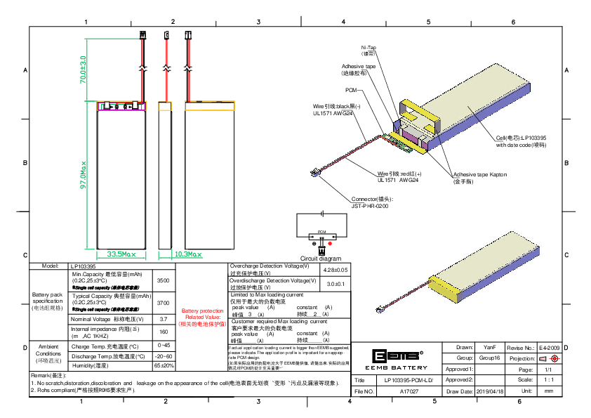
Dimensions
Height: 70.0 ± 3.0 mm
Width: 33.5 mm
Depth: 10.3 mm
Battery Pack Specification
| Specification | Value |
|---|---|
| Min. Capacity (0.2C, 25±3°C) | 3500 mAh |
| Typical Capacity (0.2C, 25±3°C) | 3700 mAh |
| Nominal Voltage | 3.7 V |
| Internal Impedance (AC 1KHz) | ≤ 160 mΩ |
Ambient Conditions
| Condition | Value |
|---|---|
| Charge Temperature | 0 ~ 45 °C |
| Discharge Temperature | -20 ~ 60 °C |
| Humidity | 65 ± 20% |
Safety and Protection Features
| Feature | Value |
|---|---|
| Overcharge Detection Voltage | 4.28 ± 0.05 V |
| Overdischarge Detection Voltage | 3.0 ± 0.1 V |
| Limited Max Loading Current (Peak) | 3 A |
| Limited Max Loading Current (Constant) | 2 A |
| Customer Required Max Loading Current (Peak) | [Not Specified] |
| Customer Required Max Loading Current (Constant) | [Not Specified] |
Note: If the actual application loading current exceeds EEMB's suggested values, please indicate. The application profile is crucial for appropriate PCM design.
Component Description and Diagram
The battery pack consists of a cylindrical lithium polymer cell (LP103395) with an integrated Protection Circuit Module (PCM). The components are connected via wires and a JST-PHR-0200 connector.
Diagrammatic Representation:
Overall Structure: The battery pack is a rectangular prism with specified dimensions (70.0±3.0 mm height, 33.5 mm width, 10.3 mm depth). It features external connections for power output.
Key Components Identified:
- Cell: EEMB LP103395 with date code marking.
- Protection Circuit Module (PCM): Manages battery safety functions.
- Ni-Tap: A nickel tab used for cell connection.
- Wires: Red wire for positive (+) and black wire for negative (-), identified as UL1571 AWG24.
- Connector: JST-PHR-0200 for external connection.
- Adhesive Tape: Used for insulation and securing components, including Kapton tape.
Circuit Diagram:
The circuit diagram illustrates the PCM connected in series with the battery cell, managing charge and discharge paths.
Remarks
- The cell appearance must be free from scratches, distortion, discoloration, and leakage.
- The product is RoHS compliant.
Document Information
Drawn by: YanF
Revision Number: E4-2009
Page: 1/1
Scale: 1:1
Draw Date: 2019/04/18
Unit: mm