Product Information
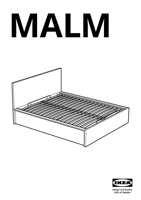
This document provides assembly instructions for the IKEA MALM bed. Please read all instructions carefully before beginning assembly. This bed frame features a lift-up storage mechanism.
Brand: IKEA
Model: MALM
Document ID: AA-2055625-9
Important Safety Information & Tools
Tools Required:
- Phillips head screwdriver ?
- Flathead screwdriver ?
- Allen key (usually included) ?
- Wrench (included) ?
Assembly Recommendations:
- Assembly by two people is recommended.
- Assemble on a soft, clean surface (like a rug or the packaging material) to avoid scratching the floor or the product.
- Ensure all parts are present before starting.
- Keep small parts away from children.
- If you need assistance or replacement parts, contact IKEA.
Parts List
- Large threaded bolt (for frame) 4x
- Medium threaded bolt (for frame) 4x
- Small threaded bolt (for frame) 8x
- Long wooden dowel 5x
- Short wooden dowel 16x
- Cam lock (part A) 8x
- Cam lock (part B) 4x
- Allen key (large) 1x
- Corner bracket 4x
- Nut 4x
- Wrench tool 1x
- Large bolt (for gas spring mechanism) 4x
- Medium bolt (for gas spring mechanism) 2x
- Small bolt (for gas spring mechanism) 2x
- Cam lock housing 4x
- Small screw (for various fittings) 46x
- Plastic cap/cover 2x
- Allen key (small) 1x
- Gas spring mounting bracket (angled) 1x
- Gas spring mounting bracket (flat) 1x
- Drawer runner bracket (left) 1x
- Drawer runner bracket (right) 1x
- Bed base support rail 2x
- Gas spring rod end fitting 4x
- Bolt (for gas spring connection) 2x
- Nut (for gas spring connection) 2x
- Gas spring cylinder 2x
- Bed base support strut 1x
- Bed base support strut end cap 24x
- Lifting handle 1x
- Bed base panel 32x/34x
- Lifting mechanism hinge plate 4x
- Lifting mechanism hinge plate (smaller) 1x
- Wooden support piece 64x/68x
Assembly Steps
Step 1: Prepare Base Panels
Two people are shown laying out the main base panels on the floor. Ensure the correct side is facing up, indicated by pre-drilled holes for subsequent steps.
Step 2: Attach Frame Supports
Using the provided wrench and bolts (4x, part 113453), attach the side frame support pieces to the base panels. Ensure the bolts are tightened securely.
Step 3: Insert Wooden Dowels
Insert short wooden dowels (16x, part 101367) into the designated holes on the frame components. A visual shows a dowel being inserted and then a crossed-out image indicating incorrect insertion (e.g., not fully inserted).
Step 4: Connect Frame Sections
Connect the frame sections using cam lock screws (8x, part 130618). Insert the screws into their respective holes. A magnified view shows the screw being inserted and then a cam lock (part 115311) being rotated to secure it.
Step 5: Attach Side Panels
Slide the side panels into place, aligning them with the dowels and screw holes. Arrows indicate the direction of movement. A close-up shows how to align the parts.
Step 6: Secure Side Panels
Use cam locks (8x, part 115311) to secure the side panels to the frame. Rotate the cam locks with a screwdriver to tighten. A magnified view shows the cam lock mechanism.
Step 7: Attach Base Support Rails
Attach the main base support rails (2x) to the side panels using dowels (4x, part 100049) and cam locks (4x, part 114670). The diagram shows inserting dowels and then securing with cam locks.
Step 8: Attach Vertical Supports
Attach the vertical support pieces to the base structure. This involves using dowels (4x, part 100049) and cam locks (4x, part 114670). The diagram shows inserting dowels and securing with cam locks, with magnified views for clarity.
Step 9: Insert Long Dowels
Insert long wooden dowels (5x, part 101359) into the designated holes on the frame. A warning icon ⚠️ is shown next to a diagram of dowels, implying correct insertion is crucial.
Step 10: Assemble Slats Support Frame
Assemble the slats support frame. This involves connecting wooden pieces using bolts (4x, part 113453) and a wrench. A magnified view shows the bolt and wrench connection.
Step 11: Secure Slats Support Frame
Further secure the slats support frame using specific brackets and bolts. Magnified views show the attachment of brackets (4x, part 114254) and the use of bolts (4x, part 122998) and cam locks.
Step 12: Install Base Rollers/Supports
Attach the base support components, such as rollers (4x, part 124252), to the underside of the bed frame. This step involves screws (46x, part 123850) and plastic caps (2x, part 190018).
Step 13: Attach Bed Base Panels
Place and secure the bed base panels. This step involves inserting dowels and using cam locks (4x, part 123849) to connect them to the frame. Magnified views show the connection points.
Step 14: Attach Lifting Mechanism Brackets (Angled)
Attach the angled lifting mechanism brackets (1x, part 124390) to the side of the bed frame using screws (4x, part 109021).
Step 15: Attach Lifting Mechanism Brackets (Flat)
Attach the smaller flat lifting mechanism brackets (1x, part 124249) to the bed frame using screws (1x, part 109021).
Step 16: Connect Gas Spring Mounts
Attach the gas spring mounting components (2x, part 123849) to the bed frame. A magnified view shows the connection using bolts and nuts.
Step 17: Attach Gas Spring Mechanism (Left Side)
Connect the left gas spring assembly (1x, part 123830) to the bed frame. This involves using bolts (2x, part 123851) and nuts (2x, part 123850). A warning icon ⚠️ indicates incorrect bolt usage.
Step 18: Attach Gas Spring Mechanism (Right Side)
Connect the right gas spring assembly (1x, part 123830) to the bed frame. Similar to step 17, use bolts (2x, part 123851) and nuts (2x, part 123850). A warning icon ⚠️ indicates incorrect bolt usage.
Step 19: Secure Lifting Mechanism
Finalize the attachment of the lifting mechanism. This step involves securing various points with screws (10x, part 109021).
Step 20: Prepare Bed Slats
Lay out the bed slats. A warning icon ⚠️ indicates not to place them incorrectly. Ensure they are oriented correctly for installation.
Step 21: Install Slats Support Struts
Attach the bed base support struts (part 108490) to the frame. This step uses screws (8x, part 158998) and dowels. Magnified views show the connection details and a warning about incorrect assembly.
Step 22: Attach Bed Frame Crossbars
Connect the main crossbars of the bed frame. This involves using bolts (2x, part 108490) and nuts (part 158998). A magnified view shows the connection. The diagram also shows a final rotated view of the assembled frame.
Step 23: Attach Central Bed Base Support
Attach the central bed base support. This uses bolts (4x, part 115461) and nuts (part 105107). A warning icon ⚠️ shows incorrect bolt usage.
Step 24: Position and Secure Frame
Two people are shown lifting and positioning the assembled bed frame. The frame is then secured to the base using bolts (6x, part 124584).
Step 25: Connect Lifting Mechanism Actuators
Connect the gas spring actuators to the bed frame. This involves attaching them using bolts (2x, part 123848). A magnified view shows the connection point.
Step 26: Finalize Gas Spring Attachment
Complete the attachment of the gas spring mechanism. This involves connecting the gas spring cylinders (2x, part 123852) to the frame. Magnified views show the connection points and a warning about incorrect assembly.
Step 27: Attach Gas Spring Support Bracket
Attach the gas spring support bracket (part 1000049) to the frame. This uses bolts (6x) and nuts.
Step 28: Secure Lifting Mechanism Handle
Attach the handle (1x, part 124390) for the lifting mechanism. This involves screws (1x, part 110440) and brackets (part 124573, 100001, 105107).
Step 29: Test Lifting Mechanism
Two people are shown carefully operating the lifting mechanism to test its function. An arrow indicates the direction of movement.
Step 30: Secure Gas Spring Attachment Points
A close-up view shows the final securing of the gas spring attachment points.
Step 31: Install Bed Base Panels
Install the bed base panels (32x/34x, part 124663) onto the frame. These panels form the surface for the mattress.
Step 32: Final Check of Lifting Mechanism
A final check of the lifting mechanism is shown. A warning icon ⚠️ indicates incorrect operation, while a checkmark icon ✔️ indicates correct operation.
Step 33: Place Mattress & Weight Limits
Place the mattress onto the bed base. The diagram shows two mattresses being stacked, implying they should be placed one by one. A table shows maximum weight limits for different mattress sizes:
- Full/Double: 40kg
- 140cm: 40kg
- 150cm: 50kg
- Standard King: 50kg
- Queen: 50kg
- 160cm: 50kg
- 180cm: 60kg
Warning: Do not exceed the maximum weight limit. A warning icon ⚠️ indicates incorrect mattress placement or overloading.
Step 34: Operate Lifting Mechanism Safely
Instructions on safely operating the lifting mechanism. Multiple warning icons ⚠️ show dangerous scenarios, such as placing body parts under the lifting mechanism or allowing children near it.
Step 35: Attach Additional Slats Support
Attach additional support pieces to the bed frame. This step involves screws (24x, part 157409).
Step 36: Final Assembly Check
A final check of the assembled bed, particularly the lifting mechanism, is shown. A warning icon ⚠️ indicates incorrect assembly or operation.
Additional Information
Copyright: © Inter IKEA Systems B.V. 2017
Date: 2023-11-17
Document ID: AA-2055625-9
