File info: application/pdf · 92 pages · 8.20MB
Tranquility Vertical Stack (TSM) Series - ClimateMaster
ECM-CV Blower Performance Data 46. Table of Contents. TSM Vertical Stack. page number is shown next to part number (e.g. LC994 - 3 ...
ClimateMaster works continually to improve its products. As a result, the design and specifications of each product at the time of order may be changed without notice and may not be as described herein.
Extracted Text
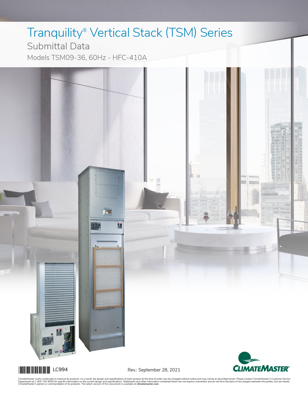
Tranquility� Vertical Stack (TSM) Series
Submittal Data
Models TSM09-36, 60Hz - HFC-410A
Rev.: September 28, 2021
ClimateMaster works continually to improve its products. As a result, the design and specifications of each product at the time of order may be changed without notice and may not be as described herein. Please contact ClimateMaster's Customer Service Department at 1-405-745-6000 for specific information on the current design and specifications. Statements and other information contained herein are not express warranties and do not form the basis of any bargain between the parties, but are merely ClimateMaster's opinion or commendation of its products. The latest version of this document is available at climatemaster.com.
Table of Contents
TSM Vertical Stack
Introduction
4
Features, Options and Accessories
5
iGate� Advanced Communicating Controls
6
Constant Volume (CV) � ECM
7
vFlow� Modulating Water Valve
8
Selection Procedure
9
TSM Series Nomenclature � Cabinet 11
TSM Series Nomenclature � Chassis 14
TSM Series Accessory Nomenclature 16
Performance Data � AHRI/ASHRAE/ISO 13256-1 19
Performance Data � Selection Notes 20
Performance Data � TSM09 with PSC Motor 21
Performance Data � TSM12 with PSC Motor 22
Performance Data � TSM15 with PSC Motor 23
Performance Data � TSM18 with PSC Motor 24
Performance Data � TSM24 with PSC Motor 25
Performance Data � TSM30 with PSC Motor 26
Performance Data � TSM36 with PSC Motor 27
Performance Data � TSM09 with ECM Motor 28
Performance Data � TSM12 with ECM Motor 29
Performance Data � TSM15 with ECM Motor 30
Performance Data � TSM18 with ECM Motor 31
Performance Data � TSM24 with ECM Motor 32
Performance Data � TSM30 with ECM Motor 33
Performance Data � TSM36 with ECM Motor 34
Air Flow Correction Table and Water Pressure Drop Adders 35
Antifreeze Correction Table 36
Performance Data � Correction Tables 38
Blower Performance Data � TSM09 (PSC/ ECM-CT/ECM-CV) 39
Blower Performance Data � TSM12 (PSC/ ECM-CT/ECM-CV) 40
Blower Performance Data � TSM15 (PSC/ ECM-CT/ECM-CV) 41
Blower Performance Data � TSM18 (PSC/ ECM-CT/ECM-CV) 42
Blower Performance Data � TSM24 (PSC/ ECM-CT/ECM-CV) 43
Blower Performance Data � TSM30 (PSC/ ECM-CT/ECM-CV) 44
Blower Performance Data � TSM36 (PSC/ ECM-CT/ECM-CV) 45
ECM-CV Blower Performance Data 46
Document page number is shown next to part number (e.g. LC994 - 3 = page 3). Since not all pages are typically used in the submittals process, the page number in the lower right corner can still be used (page ____of_____).
ClimateMaster works continually to improve its products. As a result, the design and specifications of each product at the time of order may be changed without notice and may not be as described herein. Please contact ClimateMaster's Customer Service Department at 1-405-745-6000 for specific information on the current design and specifications. Statements and other information contained herein are not express warranties and do not form the basis of any bargain between the parties, but are merely ClimateMaster's opinion or commendation of its products. The latest version of this document is available at climatemaster.com.
LC994 - 2
Page ______ of ______
Table of Contents
TSM Vertical Stack
Physical Data 47 Electrical Data - PSC Low Static Motor (208/230V) and (265V) 48
Electrical Data - ECM-CV Motor (208/230V) and (265V) 49 Electrical Data - ECM-CT Motor (208/230V) and (265V) 50
Typical Unit - Exploded View 51 TSM � Standard Unit, Furred In Cabinet with Risers 52
TSM � Leader Unit, Furred In Cabinet 53 TSM � Follower Unit, Furred In Cabinet, No Risers 54
Leader/Follower Cabinet 55 Cabinet Dimensions 56
Cabinet Slot Dimensions and Riser Arrangements 57 TSM Cabinet Configurations 58
Typical Cabinet w/"G" Panel Installation 59 Typical Recessed Cabinet w/"G" Panel and Frame Installation 60
Hinged "G" Style Return Air Panel � AVHSG Series 61 "L" Style (Flush Mounted) Return Air Panel � AVHRL Series 62
Hose Kits and Stands 63 Supply Air Openings and Grilles 64
Thermostats 66 TSM Cabinet Options 68
Riser Definitions 69 Riser GPM Definitions and Sizing 70
Riser Diameter Sizing 71 Swage Riser Length Definitions and Sizing 72 Swage Riser Extension Definitions and Sizing 73
Setting Cabinet 74 Slab Slot Chart - 3 Pipe 75
Shipping 76 Engineering Specifications 78 Pre-Engineered Factory Design Specials 91
Performance Sheet 92 Revision History 93
ClimateMaster works continually to improve its products. As a result, the design and specifications of each product at the time of order may be changed without notice and may not be as described herein. Please contact ClimateMaster's Customer Service Department at 1-405-745-6000 for specific information on the current design and specifications. Statements and other information contained herein are not express warranties and do not form the basis of any bargain between the parties, but are merely ClimateMaster's opinion or commendation of its products. The latest version of this document is available at climatemaster.com.
LC994 - 3
Page ______ of ______
Introduction
TRANQUILITY� VERTICAL STACK (TSM)SERIES WITH EARTHPURE� REFRIGERANT
The Tranquility� Vertical Stack (TSM) Series offers an innovative, labor-saving solution for spaces where individual, quiet control of the heating and cooling systems is important. Vertical stack products are designed for multi-story buildings where floor to floor footprints are similar. They utilize vertically mounted water lines known as risers installed in a wall or mechanical shaft to minimize space, material, and connections. The TSM system consists of two major components � a cabinet located behind a finished wall and a slide in and out refrigeration chassis. This allows for the riser and cabinet pieces of the system to be installed early in the construction phase so they can be framed around without exposing the refrigeration chassis to the harsh construction environment. At the finishing stages of construction when the system is ready to be commissioned, the slide in chassis is quickly and easily installed. The TSM system offers a proven solution that is designed and manufactured in America, exceeds ASHRAE 90.1 efficiencies, contractor/ technician friendly, has a compact foot print minimizing its impact on salable space, maximizes comfort levels of occupants, and has been proven as a preferred system in thousands of multi-story building applications across North America.
The TSM series is available in seven sizes ranging from 3/4 ton (2.6 kW) through 3 tons (10.6 kW). The cabinet has been designed with flexibility offering five different supply air locations and four different riser connection locations that can be factory or field configured. The chassis is designed for quick installation with two water hose connections and three or four electrical quick connectors. Both pieces of the system offer options to increase a buildings energy efficiency. Integrated water control options save system watts by preventing over pumping both when the unit is in operation and when its not. ECM fan motors maximize the systems airflow movement efficiency. Industry exclusive advanced communicating controls offer reduced startup and commissioning time by providing an easy to read gateway into the systems operating conditions.
is then isolated from the cabinet base with a second layer of grommets under the condensate pan to provide superior sound attenuation by design. ClimateMaster offers an Ultra-Quiet sound attenuation package and cabinet isolation pad to meet the demand of the most sound sensitive applications.
iGate� technology provides technicians an interface into the operation of the system in real time without the need for hard tooling. On board advanced controls communicate the key operating temperatures allowing technicians to start-up, commission, and service the equipment through a hand-held service tool which is easily connected without removing any unit hardware. Not only does iGate monitor current performance, it also offers the functionality to make system adjustments and captures operating conditions in the event of a system safety shut down. All this information is displayed in an easy to read format improving the usability of the experience.
vFlow� variable water flow technology takes water flow control and system operating range to the next level. The functionality of an on/off water valve and water flow regulator are combined into one modulating water valve component. With a modulating valve water flow is controlled to maintain a set temperature difference between entering and leaving water while in normal operation. When in extreme entering water conditions the vflow system switches its operation to maintain a leaving water temperature. With the functionality to control water flow to a leaving water temperature, the TSM's operational range is expanded beyond other water source heat pumps with an ability to function in heating or cooling modes across the entire entering water range of 30�120�F. While not in operation the valve remains closed preventing excessive water flow. vFlow increases system water flow efficiency by only allowing the right amount of water flow needed when it needs. Advanced iGate controls paired with the vFlow system provide functionality and efficiency unmatched in the marketplace.
The TSM Vertical Stack Water-Source Heat Pump Series provides energy efficiency with superior sound attenuation by design while offering options flexibility, field convertibility, and unmatched industry leading technology.
High-end condos/apartments/hotels demand the highest level of occupant comfort. Not only is it important for the system to provide heating, cooling, and dehumidification it must do so at quiet operating levels. ClimateMaster's double isolation compressor mounting system makes the TSM Series the quietest vertical stack unit on the market. Compressors are mounted on specially engineered soundtested isolation grommets to a heavy gauge base pan, which
New September 2020
� Added Pre-Engineered Factory Design Specials Section
� 3-way water valves � New thermostat options � Document update � DDC chassis controls harness options
ClimateMaster works continually to improve its products. As a result, the design and specifications of each product at the time of order may be changed without notice and may not be as described herein. Please contact ClimateMaster's Customer Service Department at 1-405-745-6000 for specific information on the current design and specifications. Statements and other information contained herein are not express warranties and do not form the basis of any bargain between the parties, but are merely ClimateMaster's opinion or commendation of its products. The latest version of this document is available at climatemaster.com.
LC994 - 4
Page ______ of ______
Features, Options and Accessories
FEATURES
� Sizes 09 (3/4 ton, 2.6 kW) through 36 (3 ton, 10.6 kW) � Environmentally-friendly EarthPure� (HFC-410A) zero
ozone depletion refrigerant � High efficiency rotary and scroll compressors � Exceeds ASHRAE 90.1 efficiencies � Removable chassis allows staged installation and ease
of maintenance � Coaxial heat exchanger � Galvanized steel cabinet � Chassis rests on rubber grommeted isolated condensate
pan for vibration reduction � Double isolation of compressor for quiet operation � TXV metering device � Cabinet construction for unit or remote-mounted
controls � PSC fans capable of two speeds � Microprocessor controls with 8 standard safeties � Unit Performance Sentinel performance monitoring
system � Integrated drain pan with condensate overflow sensor � Field convertible supply air on all sides and the top � Field convertible riser supply, return, and condensate
locations on the left, right, or back sides
OPTIONS
� iGate� Advanced Communicating Controls � Provides real-time unit operating conditions � Reduces start-up and commissioning times by removing the need for hard tooling to take temperature measurements � Captures operating conditions in the event of a safety shutdown � Provides direct control over intelligent constant volume (CV) ECM fan motor and vFlow modulating water valve � Service tool is quickly connected without the need to remove any unit hardware
� vFlow� modulating water flow � Modulates water flow to maintain a water temperature differential � Changes operation to modulate to a leaving water temperature during extreme entering water temperatures � Provides ultimate variable water flow control � Functionally operates as both a water flow regulator and water close off valve
� 2" Filter Rail to support higher indoor air quality filters � BACnet (MSTP), Modbus and Johnson N2 compatibility
options for DDC controls � Factory configured supply air openings with or without
dust protection
� Full port shut-off valves with memory stop, for supply and return risers.
� Unit integrated power disconnect � Field quick connect thermostat whips in 15', 25', and 35'
lengths � Factory mounted high density rubber isolation pad � Easy to clean rust prohibitive stainless steel drain pans � High efficient ECM fan motors
� Intelligent Constant Volume (CV) ECM motors for ultimate airflow control
� Entry level Constant Torque ECM motors that provide efficiency at a value
� Extended range insulation for geothermal applications � Auto flow regulators that limit water flow to the unit
preventing system over pumping � Two-way motorized water valves that prevent water
flow through the unit when it is not in operation increasing system pumping efficiency (fail open of fail closed options) � Three-way motorized water valves that allow continues water flow through the water loop, reducing pressure drop when the unit is not in operation (usually applied on the top floor of a system) � Internally mounted water pump for single pipe systems � Corrosive resistant cupro-nickel water heat exchanger � RIB relay (sizes 09-18) box for quiet contactor closer � UltraQuiet sound attenuation package � Tin-lated air coils for added protection from formicary corrosion
ACCESSORIES
� Copper risers � Swedged ends ready for quick drop in connection when brazing is used � End treatment ready for crimped (torch-less) style connections
� Unit stands that prevent clearance issues with tall baseboards
� Single, Double, and Double deflection with opposed dampers supply air grilles
� Fresh air frame kit for connection to outdoor air ducting � Flush Mounted Return Air Panel (L Style) with fixed
frame and removable panel for easy chassis access/ removal � Attractive return air panel with hinged access door (G style) � Key Lock Option � Stainless steel braided hose kits for connection from piping risers to the chassis � Selection of thermostats including programmable, Wi-Fi, and color touch screen � Filters - 1" (Merv 8 or 11) or 2" (Merv 8 or 13)
ClimateMaster works continually to improve its products. As a result, the design and specifications of each product at the time of order may be changed without notice and may not be as described herein. Please contact ClimateMaster's Customer Service Department at 1-405-745-6000 for specific information on the current design and specifications. Statements and other information contained herein are not express warranties and do not form the basis of any bargain between the parties, but are merely ClimateMaster's opinion or commendation of its products. The latest version of this document is available at climatemaster.com.
LC994 - 5
Page ______ of ______
iGate� Advanced Communicating Controls
iGate� - Information gateway to monitor, control, and diagnose your system
Tranquility� Vertical Stack (TSM) Series offers the industry's first 2-way communicating gateway that allows user to interact with the system in an easy to read and understandable format. The technology is designed to improve reliability and efficiency by precisely controlling variable speed components.
Configure & Monitor � Technicians have the ability to configure airflow, water temperature differential, unit options, and demand reduction. Users can view the systems status in real time through the use of sensor readings.
Precise Control � The new DXM2 board enables intelligent, 2-way communication between the DXM2 board and smart components like the communicating thermostat/ service tool, CV ECM fan motor, and vFlow� modulating water valve. The DXM2 board uses information received from the smart components and sensors to precisely control unit operation as well as to deliver higher efficiency, quieter operation, reliability and increased comfort.
Diagnostics � iGate takes diagnosing water source heat pumps to a next level of simplicity, by providing a dashboard of system and fault information, in plain English, on the iGate thermostat or service tool. iGate Service Warning feature displays fault description, possible causes and current system status (temperature readings, fan RPM and water flow status) which may be reported to service personnel.
In iGate Service Mode, the service personnel can access fault description, possible causes and most importantly, the conditions (temp, flow, i/o conditions, configuration) at the time of the fault. Manual Operation mode allows the service personnel to manually command operation for any of the thermostat outputs, blower speed, as well as pump speed or valve position from the thermostat, to help troubleshoot specific components.
With iGate communicating controls, technicians have a gateway to system information never before available and exclusive to ClimateMaster vertical stack products.
AIRFLOW SELECTION HEAT STAGE 1 HEAT STAGE 2 AUXILIARY HEAT EMERGENCY HEAT COOL STAGE 1 COOL STAGE 2 COOL DEHUMID 1 COOL DEHUMID 2 CONTINUOUS FAN HEAT OFF DELAY COOL OFF DELAY
PREVIOUS
CFM 600 750 850 850 525 700 425 550 350 60 30 NEXT
POSSIBLE FAULT CAUSES LOW WATER COIL TEMP
LOW WATER TEMP - HTG LOW WATER FLOW - HTG LOW REFRIG CHARGE - HTG INCORRECT LT1 SETTING BAD LT1 THERMISTOR
PREVIOUS
FAULT TEMPERATURE CONDITIONS LT1 LOW WATER TEMP
HEAT 1 11:11 AM 11/14
LT1 TEMP LT2 TEMP HOT WATER EWT COMP DISCHARGE LEAVING AIR LEAVING WATER ENTERING WATER CONTROL VOLTAGE
28.1 97.3 121.5 157.7 92.7 34.9 42.1 26.4
PREVIOUS
ClimateMaster works continually to improve its products. As a result, the design and specifications of each product at the time of order may be changed without notice and may not be as described herein. Please contact ClimateMaster's Customer Service Department at 1-405-745-6000 for specific information on the current design and specifications. Statements and other information contained herein are not express warranties and do not form the basis of any bargain between the parties, but are merely ClimateMaster's opinion or commendation of its products. The latest version of this document is available at climatemaster.com.
LC994 - 6
Page ______ of ______
Constant Volume (CV) � ECM
The Intelligent Constant Volume (CV) ECM blower motor provides unmatched functionality that
saves installing and service technicians time while also providing increased comfort levels to occupants.
CV ECM's are programed to maintain a constant CFM across a wide range of external static pressures (ESP). This functionality differs from traditional PSC or even Constant Torque (CT) ECM's. With tradition PSC and CT ECM fan motors as ESP is increased, CFM is reduced. To increase or decrease the speed of the fan motor requires a fan motor switch or a technician to wire into a different motor tap. CT ECM's provide increased efficiency over PSC motors but with no additional functionality. With a CV ECM as changes in ESP occur the fan motor will adjust its speed to deliver the desired CFM (within its operating range). This ensures the system is delivering the airflow and capacity it was designed for.
A major benefit of the CV ECM over other fan motor types its ability to adjust airflow through the iGate communication service tool or thermostat. Airflow levels can be adjusted in increments of 25 CFM from the units minimum and maximum CFM range (see ECM-CV configuration table for details). This functionality allows technicians to dial in airflow during start-up and commissioning via an easy to use service tool. The service tool is connected to the unit without the removal of any hardware making it easy to get to by simply opening the return air panel. During operation occupants may have a desire for airflow adjustments. Reducing CFM can reduce airflow sound levels and increase cooling dehumidification (latent capacity). Technicians can easily make these adjustments without the need to remove unit hardware or make wiring changes reducing service time with minimal disruption to the occupants.
The fan motor operating modes include: � First Stage Cooling (Y1 & O) � Second Stage Cooling (Y1, Y2, & O) � First Stage Heating (Y1) � Second Stage Heating (Y1 & Y2) � Fan (G with no Y1, Y2, or W)
The CV ECM motor includes "soft start" and "ramp down" features. The soft start feature gently increases the motors rpm at blower start up resulting quieter blower start cycles. Likewise, the ramp down feature allows the blower to slowly decrease rpm to a full stop resulting in a quieter end to each blower cycle. The ramp down feature (also known as the heating or cooling "Off Delay") also has the functionality to be field selected by the technician in the allowable range of 0 to 255 seconds.
Communicating Thermostat
ECM-CV Blower Motor
Service Tool
Two-Way Communication One-Way Communication
Temperature sensors (6x) LTI, LT2, LAT EWT, LWT,
COMPR Discharge
AIRFLOW SELECTION HEAT STAGE 1 HEAT STAGE 2 AUXILIARY HEAT EMERGENCY HEAT COOL STAGE 1 COOL STAGE 2 COOL DEHUMID 1 COOL DEHUMID 2 CONTINUOUS FAN HEAT OFF DELAY COOL OFF DELAY
CFM 600 750 850 850 525 700 425 550 350 60 30
PREVIOUS
NEXT
Airflow Configuration Screen on Communicating Thermostat or Service Tool
ClimateMaster works continually to improve its products. As a result, the design and specifications of each product at the time of order may be changed without notice and may not be as described herein. Please contact ClimateMaster's Customer Service Department at 1-405-745-6000 for specific information on the current design and specifications. Statements and other information contained herein are not express warranties and do not form the basis of any bargain between the parties, but are merely ClimateMaster's opinion or commendation of its products. The latest version of this document is available at climatemaster.com.
LC994 - 7
Page ______ of ______
Communicating Thermostat
Or
Communicating Diagnostic Tool
Two-Way Communication One-Way Communication
vFlow� Modulating Water Valve
DXM2
Temperature sensors (6x) LTI, LT2, LAT EWT, LWT,
COMPR Discharge
vFlow� Motorized modulating water valve
vFlow� Internal Variable Water Flow
Industry-first, Built-in vFlow� provides an ultra-highefficient internal water flow system. It saves installers time and labor by avoiding installing bulky valves or flow regulators in the field. Multi-unit installations are also much simpler with vFlow systems, as the units automatically adjust water flow across the system.
vFlow is enabled by iGate�, which facilitates intelligent communication between the thermostat, DXM2 control, sensors and modulating valve to make true variable water flow a reality.
In applications using the vFlow water flow control, when the motorized modulating valve slows down the external pump, consumes fewer watts, thus saving more energy.
vFlow� delivers four main benefits:
1. One component replaces 2 way motorized valve and auto flow regulator
2. Superior reliability by varying the water flow to deliver more stable operation
3. Higher cost savings by varying water flow (and pump watt consumption) to match the unit's mode of operation
4. Allows unit to safely operate in cooling mode or heating mode from 20�F to 120�F
Modulating Water Valve Operation:
When the unit is in cooling or heating, the DXM2 controller monitors the entering and leaving water temperature. Based on the desired water temperature differential (delta T), the DXM2 sends a voltage signal to the valve which correlates to a percentage open in order to achieve the water flow needed. As conditions change the voltage signal will readjust the valve for the needed water flow.
The modulating water valve is factory set for a water delta T of 10F for cooling operation and 7F for heating operation. This default setting is estimated to be approximately 3 GPM of water flow per ton of load capacity. Installers can change the water flow by adjusting the delta T upward for lower flow or downward for higher flow by using the communicating thermostat or service tool. Please see unit IOM for full instructions.
At low cooling EWT's and high heating EWT's the DXM2 software overrides the delta T settings and adjusts the valve to operate to a LWT of no less than 60F for cooling and no greater than 70F for heating.
Units with the modulating water valve will operate at EWT's from 30�F to 120�F in BOTH cooling and heating. When there is no demand for cooling or heating, the valve will be fully closed or can be field configured to remain slightly open allowing some water to pass through.
vFlow water flow controls are unmatched in the market and exclusive to ClimateMaster vertical stack products.
ClimateMaster works continually to improve its products. As a result, the design and specifications of each product at the time of order may be changed without notice and may not be as described herein. Please contact ClimateMaster's Customer Service Department at 1-405-745-6000 for specific information on the current design and specifications. Statements and other information contained herein are not express warranties and do not form the basis of any bargain between the parties, but are merely ClimateMaster's opinion or commendation of its products. The latest version of this document is available at climatemaster.com.
LC994 - 8
Page ______ of ______
Reference Calculations
Heating
LWT = EWT -
HE GPM x Constant
Cooling
HR LWT = EWT + GPM x Constant
LAT = EAT +
HC CFM x1.08
LAT (DB) = EAT (DB) - SC CFM x1.08
Constant = 500 for water, 485 for antifreeze.
Selection Procedure
LC = TC - SC S/T = SC
TC
Legend and Glossary of Abbreviations
BTUH = BTU (British Thermal Unit) per hour MBTUH = 1,000 BTU per hour
TC = total cooling capacity, BTUH SC = sensible cooling capacity, BTUH S/T = sensible to total cooling ratio LC = latent cooling capacity, BTUH HC = air heating capacity, BTUH CFM = airflow, cubic feet/minute ESP = external static pressure (inches w.g.) EAT = entering air temperature LAT = leaving air temperature, �F DB = dry bulb temperature (�F) WB = wet bulb temperature (�F) EWT = entering water temperature LWT = leaving water temperature, �F TD or delta T = temperature differential
GPM = water flow in U.S. gallons/minute WPD = waterside pressure drop (psi & ft. of hd.)
HE = total heat of extraction, BTUH HR = total heat of rejection, BTUH KW = total power unit input, kilowatts EER = energy efficient ratio = BTUH output/Watt input COP = coefficient of performance = BTUH output/BTUH input MPT = male pipe thread FPT = female pipe thread HWC = hot water generator (desuperheater) capacity, Mbtuh ECM-CV = electronic commutated constant volume fan motor ECM-CT = electronic commutated constant torque fan motor MWV = motorized water valve WSE = waterside economizer VFD = variable frequency drive
Conversion Table - to convert inch-pound (English) to S-I (Metric)
Air Flow Airflow (L/s) = CFM x 0.472
Water Flow Water Flow (L/s) = gpm x 0.0631
Est Static Pressure ESP (Pa) = ESP (in of wg) x 249
Water Pressure Drop PD (kPa) = PD (ft of hd) x 2.99
ClimateMaster works continually to improve its products. As a result, the design and specifications of each product at the time of order may be changed without notice and may not be as described herein. Please contact ClimateMaster's Customer Service Department at 1-405-745-6000 for specific information on the current design and specifications. Statements and other information contained herein are not express warranties and do not form the basis of any bargain between the parties, but are merely ClimateMaster's opinion or commendation of its products. The latest version of this document is available at climatemaster.com.
LC994 - 9
Page ______ of ______
Selection Procedure
Step 1 Determine the actual heating and cooling loads at the
desired dry bulb and wet bulb conditions.
Step 2 Obtain the following design parameters: Entering water
temperature, water flow rate in GPM, air flow in CFM, water flow pressure drop and design wet and dry bulb temperatures. Air flow CFM should be between 300 and 500 CFM per ton. Unit water pressure drop should be kept as close as possible to each other to make water balancing easier. Go to the appropriate tables and find the proper indicated water flow and water temperature.
Step 3 Select a unit based on total and sensible cooling
conditions. Select a unit which is closest to, but no larger than, the actual cooling load.
Step 4 Enter tables at the design water flow and water
temperature. Read the total and sensible cooling capacities (Note: interpolation is permissible, extrapolation is not).
Step 5 Read the heating capacity. If it exceeds the design
criteria it is acceptable. It is quite normal for WaterSource Heat Pumps to be selected on cooling capacity only since the heating output is usually greater than the cooling capacity.
Step 6 Determine the correction factors associated with the
variable factors of dry bulb, wet bulb, and air flow.
Corrected Total Cooling = tabulated total cooling x wet bulb correction x air flow correction.
Corrected Sensible Cooling = tabulated sensible cooling x wet/dry bulb correction, and air flow correction.
Step 7 Compare the corrected capacities to the load
requirements. Normally if the capacities are within 10% of the loads, the equipment is acceptable. It is better to under size than oversize, as undersizing improves humidity control, reduces sound levels and extends the life of the equipment.
Step 8 When completed, calculate water temperature rise
and assess the selection. If the units selected are not within 10% of the load calculations, then review what effect changing the GPM, water temperature and/or air flow and air temperature would have on the corrected capacities. If the desired capacity cannot be achieved, select the next larger or smaller unit and repeat the procedure. Remember, when in doubt, under size slightly for best performance.
Example Equipment Selection For Cooling
Step 1 Load Determination:
Assume we have determined that the appropriate cooling load at the desired dry bulb 80�F and wet bulb 65�F conditions is as follows
Total Cooling.....................................................................17,000 BTUH Sensible Cooling..............................................................12,000 BTUH Entering Air Temp......................... 80�F Dry Bulb / 65�F Wet Bulb
Step 2 Design Conditions:
Similarly, we have also obtained the following design parameters:
Entering Water Temp....................................................................... 90�F Water Flow (Based upon 10�F rise in temp.)................... 5.1 GPM Air Flow at ESP Unit.................................. 630 CFM (90% of rated)
Steps 3, 4 & 5 HP Selection:
After making our preliminary selection (TSM18 with PSC motor), we enter the tables at design water flow and water temperature and read Total Cooling, Sens. Cooling and Heat of Rej. capacities:
Total Cooling..................................................................... 18,350 BTUH Sensible Cooling..............................................................13,210 BTUH Heat of Rejection............................................................22,470 BTUH
Steps 6 & 7 Entering Air and Airflow Corrections:
Next, we determine our correction factors.
Table Ent Air Air Flow Corrected Corrected Total Cooling = 18,350 x 0.975 x 0.971 = 17,372 Corrected Sens Cooling = 13,210 x 0.999 x 0.932 = 12,299 Corrected Heat of Reject.= 22,470 x 0.982 x 0.979 = 21,602
Step 8 Water Temperature Rise Calculation and Assessment:
Actual Temperature Rise...............................................................8.8�F
When we compare the Corrected Total Cooling and Corrected Sensible Cooling figures with our load requirements stated in Step 1, we discover that our selection is within +/- 10% of our sensible load requirement. Furthermore, we see that our Corrected Total Cooling figure is slightly undersized as recommended, when compared to the actual indicated load.
ClimateMaster works continually to improve its products. As a result, the design and specifications of each product at the time of order may be changed without notice and may not be as described herein. Please contact ClimateMaster's Customer Service Department at 1-405-745-6000 for specific information on the current design and specifications. Statements and other information contained herein are not express warranties and do not form the basis of any bargain between the parties, but are merely ClimateMaster's opinion or commendation of its products. The latest version of this document is available at climatemaster.com.
LC994 - 10
Page ______ of ______
Section Series Size
Voltage Options
Harness Controls
Power Termination Cabinet Height
TSM Series Nomenclature � Cabinet
Digit Position Value Description
1
C Non-Ducted Cabinet Series
2
1 09 - 0.75 ton
2 12 - 1 ton
3 15 - 1.25 ton
4 18 - 1.5 ton
5 24 - 2 ton
6 30 - 2.5 ton
7 36 - 3 ton
3
G 208/230/60/1
E 265/60/1
4
A Premium Seal
B Stainless Steal Drain Pan
C Premium Seal & Stainless Steal Drain Pan
0 None
1 Premium Seal & 2" Filter
2 Stainless Steal Drain Pan & 2" Filter
3 Premium Seal, Stainless Steal Drain Pan, & 2" Filter
4 2" Filter
5
A PSC fan motor, ADA mounted
B CV ECM fan motor, ADA mounted
C PSC fan motor, MPC DDC controls
D CV ECM fan motor, MPC DDC controls
L PSC fan motor
M CV ECM fan motor
N PSC fan motor, Remote mounted thermostat
P PSC fan motor, Cabinet mounted thermostat
R CV ECM fan motor, Remote mounted thermostat
S CV ECM fan motor, Cabinet mounted thermostat
1 CT ECM fan motor, ADA mounted
2 CT ECM fan motor, MPC DDC controls
3 CT ECM fan motor
4 CT ECM fan motor, Remote mounted thermostat
5 CT ECM fan motor, Cabinet mounted thermostat
6
A Disconnect switch
B Breaker
C Breaker, Internal circulating pump
D Disconnect switch, Internal circulating pump
E Internal circulating pump
0 None
7
A 88"
B 80"
C 88" with isolation pad
D 80" with isolation pad
Table Continue on Next Page
ClimateMaster works continually to improve its products. As a result, the design and specifications of each product at the time of order may be changed without notice and may not be as described herein. Please contact ClimateMaster's Customer Service Department at 1-405-745-6000 for specific information on the current design and specifications. Statements and other information contained herein are not express warranties and do not form the basis of any bargain between the parties, but are merely ClimateMaster's opinion or commendation of its products. The latest version of this document is available at climatemaster.com.
LC994 - 11
Page ______ of ______
TSM Series Nomenclature �Cabinet
Table Continue from Previous Page
Section
Digit Position Value Description
Riser Style
8
0 Follower/None
1 Standard
2 Leader
Riser Location
9
0 None
1 Shipped Separately
2 Left Back
3 Right Back
4 Left Side
5 Right Side
6 Chassis shipped in cabinet, risers shipped separately
7 Chassis shipped in cabinet, no risers, no ball valve assemblies
Riser Ball Valve Options
10
5 Standard (MNPT) Ball Valves
N None
Back/Front/Top Supply Air Locations 11
0 None
A Back Small
B Back Large
C Front Small
D Front Large
E Top
F Back Small & Top
G Back Large & Top
H Front Small & Top
J Front Large & Top
K Back Small & Front Small
L Back Large & Front Large
M Back Small & Front Large
N Back Large & Front Small
P Back Small, Front Small, & Top
Q Back Large, Front Large, & Top
R Back Small, Front Large, & Top
S Back Large, Front Small, & Top
Side Supply Air Locations
12
0 None
A Right Small
B Right Large
C Left Small
D Left Large
E Right Small & Left Small
F Right Large & Left Large
G Right Small & Left Large
H Right Large & Left Small
Table Continue on Next Page
ClimateMaster works continually to improve its products. As a result, the design and specifications of each product at the time of order may be changed without notice and may not be as described herein. Please contact ClimateMaster's Customer Service Department at 1-405-745-6000 for specific information on the current design and specifications. Statements and other information contained herein are not express warranties and do not form the basis of any bargain between the parties, but are merely ClimateMaster's opinion or commendation of its products. The latest version of this document is available at climatemaster.com.
LC994 - 12
Page ______ of ______
Section Misc. Cabinet Options
Type Revision
TSM Series Nomenclature � Cabinet
Table Continue from Previous Page
Digit Position Value Description
13
Option
Thermostat Whip SA Opening
A
No Tstat Whip
B
15' Tstat Whip
Factory
C
25' Tstat Whip
Configured
D
35' Tstat Whip
E
No Tstat Whip
F
15' Tstat Whip
Field
G
25' Tstat Whip
Configured
H
35' Tstat Whip
J
No Tstat Whip
K
15' Tstat Whip
Factory
L
25' Tstat Whip
Configured
M
35' Tstat Whip
N
No Tstat Whip
P
15' Tstat Whip
Factory
Q
25' Tstat Whip
Configured
R
35' Tstat Whip
0
No Tstat Whip
1
15' Tstat Whip
Field
2
25' Tstat Whip
Configured
3
35' Tstat Whip
4
No Tstat Whip
5
15' Tstat Whip
Factory
6
25' Tstat Whip
Configured
7
35' Tstat Whip
14
0 Standard
15
D Non-Ducted & Ducted Cabinet Series
SA Dust Cover RA Dust Cover
Yes
Yes
None
Yes
Yes
None
None
Yes
None
None
None
None
ClimateMaster works continually to improve its products. As a result, the design and specifications of each product at the time of order may be changed without notice and may not be as described herein. Please contact ClimateMaster's Customer Service Department at 1-405-745-6000 for specific information on the current design and specifications. Statements and other information contained herein are not express warranties and do not form the basis of any bargain between the parties, but are merely ClimateMaster's opinion or commendation of its products. The latest version of this document is available at climatemaster.com.
LC994 - 13
Page ______ of ______
Section Series Unit Size
Voltage Chassis Options
Controls Auto-Flow Regulator
TSM Series Nomenclature � Chassis
Digit Position Value Description
1-3
TSM Vertical Stack Non-Ducted Applications
4-5
09 09 - 0.75 ton
12 12 - 1 ton
15 15 - 1.25 ton
18 18 - 1.5 ton
24 24 - 2 ton
30 30 - 2.5 ton
36 36 - 3 ton
6
E 265/60/1
G 208-230/60/1
7
A Stainless Steal Drain Pan
B Ultra Quiet
C Stainless Steal Drain Pan & Ultra Quiet
D Stainless Steal Drain Pan & Connection to communicating thermostat
E Ultra Quiet & Connection to communicating thermostat
F Stainless Steal Drain Pan, Ultra Quiet, & Connection to communicating thermostat
G Connection to communicating thermostat
H Stainless Steal Drain Pan & RIB Relay
K Ultra Quiet & RIB Relay
L Stainless Steal Drain Pan, Ultra Quiet, & RIB Relay
M RIB Relay
N Stainless Steal Drain Pan, RIB Relay, & Connection to communicating thermostat
P Ultra Quiet, RIB Relay, & Connection to communicating thermostat
Q Stainless Steal Drain Pan, Ultra Quiet, RIB Relay, & Connection to communicating thermostat
R RIB Relay & Connection to communicating thermostat
S None
8
A CXM
B DXM2
C CXM w/MPC
D DXM2 w/MPC
9
C 1.5 GPM
D 2 GPM
E 2.5 GPM
F 3 GPM
G 3.5 GPM
H 4 GPM
J 5 GPM
K 6 GPM
L 7 GPM
M 8 GPM
N 9 GPM
P 10.5 GPM
S None
Table Continue on Next Page
ClimateMaster works continually to improve its products. As a result, the design and specifications of each product at the time of order may be changed without notice and may not be as described herein. Please contact ClimateMaster's Customer Service Department at 1-405-745-6000 for specific information on the current design and specifications. Statements and other information contained herein are not express warranties and do not form the basis of any bargain between the parties, but are merely ClimateMaster's opinion or commendation of its products. The latest version of this document is available at climatemaster.com.
LC994 - 14
Page ______ of ______
Section Water Circuit Options
Heat Exchanger Options
Heat Exchanger Options Shipping Blower Motor Standard
TSM Series Nomenclature �Chassis
Table Continue from Previous Page
Digit Position Value Description
10
S None
M 2-Way Water Valve - Fail Closed
N 2-Way Water Valve - Fail Opened
G 3-Way Water Valve
T Modulating Water Valve
P Secondary Circulating Pump
11
C Tin-Plated Air Coil & Copper Water Coil
N Tin-Plated Air Coil & Cupro-Nickel Water Coil
D Tin-Plated Air Coil, Copper Water Coil, & Insulated Tubing
E Tin-Plated Air Coil, Cupro-Nickel Coil, & Insulated Tubing
F Standard Air Coil, Copper Water Coil, & Insulated Tubing
G Standard Air Coil, Cupro-Nickel Coil, & Insulated Tubing
11
L Standard Air Coil & Copper Water Coil
M Standard Air Coil, Cupro-Nickel Coil
12
6 Chassis Ships in Cabinet (risers not attached)
S Standard
13
B PSC - Low Static (TSM Only)
C ECM - Constant Torque
D ECM - Constant Volume
14
S Standard
ClimateMaster works continually to improve its products. As a result, the design and specifications of each product at the time of order may be changed without notice and may not be as described herein. Please contact ClimateMaster's Customer Service Department at 1-405-745-6000 for specific information on the current design and specifications. Statements and other information contained herein are not express warranties and do not form the basis of any bargain between the parties, but are merely ClimateMaster's opinion or commendation of its products. The latest version of this document is available at climatemaster.com.
LC994 - 15
Page ______ of ______
TSM Series Accessory Nomenclature
Return Air Panel "G" Style
1 2 3 4 5 6 7 8 9 10 11
AVHS G 1 S F S N S
ACCESSORY VHS RETURN AIR PANEL
TYPE DESCRIPTION
"G"
Removable
UNIT WIDTH
OPTION WIDTH
1
17"
2
19"
3
24"
COLOR
S = STANDARD (POLAR ICE) W = BRIGHT WHITE
INSULATION TYPE
F = FIBERGLASS
STANDARD
S = STANDARD
REVISION LEVEL
N = CURRENT REVISION TSM/TSL ("G" PANEL)
STYLE
A = DOOR w/ADA TYPE 1 TSTAT OPTION B = DOOR w/ADA TYPE 2 TSTAT OPTION C = DOOR w/ADA TYPE 1 TSTAT OPTION & LOCK D = DOOR w/ADA TYPE 2 TSTAT OPTION & LOCK L = DOOR w/KEY LOCKS S = STANDARD DOOR
THERMOSTAT MOUNTING
TYPE 1
TYPE 2
ATP21W02 AVB32V02C
ATA11U03 ATA32V01
ATC32U03C
ATA11U01
ABV32V03C
Return Air Panel "L" Style
1 2 3 45
6 7 8 9 10 11 12 13
AVHRL 1 S F S F 0 A S
ACCESSORY VS RETURN AIR PANEL
AVHRL = L-PANEL
UNIT WIDTH
OPTION 1
WIDTH 17"
TSM/TSL 09 - 12,
2
19"
15, 18
3
24"
24
4
24"
30 - 36
COLOR
S = STANDARD (POLAR ICE) W = BRIGHT WHITE
INSULATION TYPE
F = FIBERGLASS
STANDARD
S = STANDARD
REVISION LEVEL
A = CURRENT REVISION
RESERVED FOR FUTURE USE
0 = STANDARD
COMPONENT
F = FRAME P = PANEL
STYLE
S = STANDARD
ClimateMaster works continually to improve its products. As a result, the design and specifications of each product at the time of order may be changed without notice and may not be as described herein. Please contact ClimateMaster's Customer Service Department at 1-405-745-6000 for specific information on the current design and specifications. Statements and other information contained herein are not express warranties and do not form the basis of any bargain between the parties, but are merely ClimateMaster's opinion or commendation of its products. The latest version of this document is available at climatemaster.com.
LC994 - 16
Page ______ of ______
TSM Series Accessory Nomenclature
Riser
1 2 3 4 5 6 7 8 9 10 11 12 13 14
20 M 3 0 9 8 M 1 2 A S A 0
GROUP
20 = VERTICAL STACK RISER
M = MAKE ITEM
RISER LENGTH
VALVE PACKAGE
0 = DRAIN
} 7 = 09-12
8 = 15-18 9 = 24-36
SWEAT VALVE
RISER STYLE
1 = 80" cabinet supply/return std 2 = 80" cabinet drain std 3 = 88" & 65" cabinet supply/return std 4 = 88" & 65" cabinet drain std 5 = 80" cabinet supply/return M/S 6 = 80" cabinet drain M/S 7 = 88" & 65" cabinet supply/return M/S 8 = 88" & 65" cabinet drain M/S 9 = Riser Extension - Add-On
COPPER TYPE M = M COPPER L = L COPPER
RISER TOP DIAMETER 0 = CAP 1 = 1" 2 = 1.25" 3 = 1.5" 4 = 2" 5 = 2.5" 6 = 3"
REVISION LEVEL A= CURRENT REVISION LEVEL
SPECIAL S = STANDARD A = SPECIAL #1 B = SPECIAL #2 Etc...
TYPE A = STANDARD - TOP SWAGE ONLY(3" DEEP) B = STANDARD - TOP/BOTTOM NO SWAGE E = STANDARD - TOP SWAGE ONLY(3" DEEP) "INSULATED" F = STANDARD - TOP/BOTTOM NO SWAGE "INSULATED"
RISER BOTTOM DIAMETER
0 = CAP 1 = 1"
4 = 2" 5 = 2.5"
2 = 1.25"
6 = 3"
3 = 1.5"
Hose Kit
123 4 5 6 7 8
AHH 0 5 0 3 B
Group
AHH = Accessory Hose Kit AHU = Accessory Hose Kit
Note: If cabinet digit 10 is 4 use AHH; 5 use AHU
Hose Size
050 = 1/2" Nominal 075 = 3/4" Nominal
100 = 1" Nominal
Revision Level
B = Current Revision
Length
3 = Length in Feet
Supply Air Grille
1 2 3 4 5 6 7 8 9 10 11 12 13 14
A816G A SS 1206 O A
SUPPLY AIR GRILLE
GRILLE DEFLECTION
A = SINGLE DEFLECTION B = DOUBLE DEFLECTION C = DOUBLE DEFLECTION w/OPPOSED DAMPER
MATERIAL & COLOR
SS = BRUSHED ALUMINUM SP = PAINTED ALUMINUM, POLAR ICE SW = PAINTED ALUMINUM, BRIGHT WHITE
REVISION LEVEL
A = CURRENT
SPECIAL OPTIONS
O = STANDARD Always "O" Unless Special Option Quoted From Factory
DIMENSIONS
1206 = 12"W x 6"H
Rev.: 05/04/17S
ClimateMaster works continually to improve its products. As a result, the design and specifications of each product at the time of order may be changed without notice and may not be as described herein. Please contact ClimateMaster's Customer Service Department at 1-405-745-6000 for specific information on the current design and specifications. Statements and other information contained herein are not express warranties and do not form the basis of any bargain between the parties, but are merely ClimateMaster's opinion or commendation of its products. The latest version of this document is available at climatemaster.com.
LC994 - 17
Page ______ of ______
TSM Series Accessory Nomenclature
Cabinet Stands (Ship loose in bulk for field attachment 1 2 3 4 5 6 7 8 9 10 11 12 13
A CS T 0 01 0 0 0 0 0 B
Accessory Cabinet Stand TSM/TSL
CABINET SIZE
0 = 17" x 17"
1 = 19" x 19"
2 = 24" x 24"
3 = 17" x 20"
4 = 19" x 22" 5 = 24" x 27"
HEIGHT
01 = 1"
02 = 2"
03 = 3"
04 = 4"
05 = 5"
06 = 6"
07 = 7"
08 = 8" 09 = 9"
10 = 10" 11 = 11" 12 = 12"
13 = 13"
REVISION
B = CURRENT REVISION
FUTURE USE
0 = STANDARD
FUTURE USE
0 = STANDARD
FUTURE USE
0 = STANDARD
FUTURE USE
0 = STANDARD
ISO PAD
0 = STANDARD (NO ISO PAD) 1 = ISO PAD
ClimateMaster works continually to improve its products. As a result, the design and specifications of each product at the time of order may be changed without notice and may not be as described herein. Please contact ClimateMaster's Customer Service Department at 1-405-745-6000 for specific information on the current design and specifications. Statements and other information contained herein are not express warranties and do not form the basis of any bargain between the parties, but are merely ClimateMaster's opinion or commendation of its products. The latest version of this document is available at climatemaster.com.
LC994 - 18
Page ______ of ______
Performance Data � AHRI/ASHRAE/ISO 13256-1
AHRI/ASHRAE/ISO 13256-1. English (I-P) Units
Model with ECM Motor
TSM09 TSM12 TSM15 TSM18 TSM24 TSM30 TSM36
Water Loop Heat Pump
Cooling 86�F
Heating 68�F
Capacity Btuh
EER Btuh/W
Capacity Btuh
COP
9200
14.3
12200
5.4
11800
14.1
15200
5.3
14600
15.9
17500
5.3
18000
15.2
22200
5.1
25000
15.7
32500
5.1
28000
15.1
34500
5.0
35000
14.6
40500
5.0
Ground Loop Heat Pump
Cooling 77�F
Heating 32�F
Capacity Btuh
EER Btuh/W
Capacity Btuh
COP
9700
16.2
7100
3.3
12100
16.8
9000
3.2
15500
18.8
11000
3.6
18500
17.3
13200
3.3
26500
18.5
18200
3.5
29000
17.6
22200
3.6
36000
16.5
25500
3.5
Water Loop Heat Pump
Ground Loop Heat Pump
Model with PSC Motor
TSM09
Cooling 86�F Capacity EER
Btuh 9200
Btuh/W 13.5
Heating 68�F
Capacity Btuh
COP
12200
5.0
Cooling 77�F Capacity EER
Btuh 9700
Btuh/W 14.9
Heating 32�F
Capacity Btuh
COP
7100
3.2
TSM12
11800
13.7
15200
4.9
12100
15.0
9000
3.2
TSM15
14300
13.3
18000
4.8
15200
15.6
11500
3.3
TSM18
17300
13.2
22500
4.8
18400
15.1
13500
3.2
TSM24
25000
14.4
32500
4.9
26500
16.8
18400
3.4
TSM30
27500
13.4
34500
4.7
28500
15.2
22000
3.3
TSM36
35000
14.1
40500
4.9
36000
16.2
25500
3.4
Cooling capacities based upon 80.6�F DB, 66.2�F WB entering air temperature Heating capacities based upon 68�F DB, 59�F WB entering air temperature All units AHRI/ISO/ASHRAE 13256-1 rated on high speed motor TAP All ratings based upon operation at lower voltage of dual voltage rated models
AHRI/ASHRAE/ISO 13256-1. Metric (S-I) Units
Model with ECM
Motor
TSM09 TSM12 TSM15 TSM18 TSM24 TSM30 TSM36
Water Loop Heat Pump
Cooling 30�C
Heating 20�C
Capacity kW
EER W/W
Capacity kW
COP
2.70
4.2
3.58
5.4
3.46
4.1
4.46
5.3
4.28
4.7
5.13
5.3
5.28
4.5
6.51
5.1
7.33
4.6
9.53
5.1
8.21
4.4
10.12
5
10.26
4.3
11.88
5
Ground Loop Heat Pump
Cooling 25�C
Heating 0�C
Capacity kW
EER W/W
Capacity kW
COP
2.84
4.8
2.08
3.3
3.55
4.9
2.64
3.2
4.55
5.5
3.23
3.6
5.43
5.1
3.87
3.3
7.77
5.4
5.34
3.5
8.50
5.2
6.51
3.6
10.56
4.8
7.48
3.5
Model with PSC
Motor
TSM09
Water Loop Heat Pump
Cooling 30�C
Heating 20�C
Capacity kW
EER W/W
Capacity kW
COP
2.70
4.0
3.58
5
Ground Loop Heat Pump
Cooling 25�C
Heating 0�C
Capacity kW
EER W/W
Capacity kW
COP
2.84
4.4
2.08
3.2
TSM12
3.46
4.0
4.46
4.9
3.55
4.4
2.64
3.2
TSM15
4.19
3.9
5.28
4.8
4.46
4.6
3.37
3.3
TSM18
5.07
3.9
6.60
4.8
5.40
4.4
3.96
3.2
TSM24
7.33
4.2
9.53
4.9
7.77
4.9
5.40
3.4
TSM30
8.06
3.9
10.12
4.7
8.36
4.5
6.45
3.3
TSM36
10.26
4.1
11.88
4.9
10.56
4.8
7.48
3.4
Cooling capacities based upon 27�C DB, 19�C WB entering air temperature Heating capacities based upon 20�C DB, 15�C WB entering air temperature All units AHRI/ISO/ASHRAE 13256-1 rated on high speed motor TAP All ratings based upon operation at lower voltage of dual voltage rated models
ClimateMaster works continually to improve its products. As a result, the design and specifications of each product at the time of order may be changed without notice and may not be as described herein. Please contact ClimateMaster's Customer Service Department at 1-405-745-6000 for specific information on the current design and specifications. Statements and other information contained herein are not express warranties and do not form the basis of any bargain between the parties, but are merely ClimateMaster's opinion or commendation of its products. The latest version of this document is available at climatemaster.com.
LC994 - 19
Page ______ of ______
Performance Data � Selection Notes
For operation in the lighter shaded area to determine if water
can be used in lieu of an antifreeze solution, the Leaving
Water Temperature (LWT) must bWePcDa*lculated. Flow mCouosltinbge- EAT 80/67�F
m42a�iFnt[a5in.6e�dC]towahleenvetEhl�WFseTuCcXhGMPthM/DatXtPMhSe2I LJWWFT3T
is maintained jumTpCer is nSCot
above clSipeRnpaset/iTodot
kW
HR
EER
(see example below). Othe4.r5wise3,.7appropriate levels (10� below LWT, See IOM) of a proper antifreeze should be used
in systems with leav2in0g w6a.t0er te5m.0 peratures of 42�FOp[e5ra.6tio�Cn n] ot recommended
or below and the JW3 jum9p.0er sh8.o6uld 1b9e.8clipped. This is due
to the potential of the refri4g.5eran2t.8temp6e.4ratu4r6e.3b6ein3g0.5a2s low0.66 1.62 52.07 29.0
as 32�F [0�C], which30may 6le.0ad to3.8a nui8s.8ance46c.9u0tou3t0.d81ue to0.66
the activation of the Low T9e.0mpe7r.a4 ture17P.0rote4c7.t0io8 n (3L0T.910 ). JW0.636 should never be clipped for standard range equipment or systems without antifreez4e..5 1.8 4.3 45.35 29.95 0.66
40 6.0 2.6 5.9 46.16 30.41 0.66
1.51 52.26 31.3 1.47 52.27 32.5 1.77 51.56 26.0 1.65 51.98 28.3
Example:
9.0 7.0 16.3 46.49 30.59 0.66 1.60 52.12 29.4
HC
23.28 26.08 27.35 28.06 30.51 32.12 33.01
Heating - EAT 70�F kW HE LAT COP
2.31 15.72 85.9 3.0 2.35 18.36 88.1 3.2 2.37 19.56 89.1 3.4 2.38 20.23 89.6 3.4 2.42 22.56 91.5 3.7 2.45 24.08 92.7 3.8 2.46 24.92 93.4 3.9
At 50�F EWT (Entering W4a.5ter T0e.9mper2a.1ture4)4a.0n1d 129.5.22gpm0/ .66 ton, a 3 ton unit has 5a0 HE 6o.f0 26,82.430 B5tu.6h. T4o5.c0a6 lcu2l9a.7t9e LW0T.6,6 rearrange the formula for H9.0E as4f.o7llow1s0.:7 45.52 30.05 0.66
1.94 50.82 22.9 35.03 2.49 26.83 95.0 4.1 1.80 51.40 25.3 36.94 2.52 28.65 96.4 4.3 1.74 51.65 26.4 38.00 2.54 29.65 97.3 4.4
HE = TD x GPM x 500, wh4e.5re H0E.9= He2.a0t of4E2.x3t6rac2t8i.o34n (Bt0u.6h7);
TD = temperature di6ff0eren6c.0e (EW2.3T - L5W.3 T) a43n.6d2 GP29M.01= U.S0..67
Gallons per Minute.
9.0 4.4 10.3 44.20 29.32 0.66
2.15 49.89 19.9 1.99 50.60 22.2 1.91 50.93 23.3
39.53 41.72 42.91
2.56 31.09 98.4 4.5 2.60 33.15 100.1 4.7 2.62 34.28 101.0 4.8
TD = HE / (GPM x 500) 4.5
0.8
1.8 40.44 27.36
0.68
2.40 48.83 17.0 43.95 2.64 35.25 101.8 4.9
70 6.0 2.2 5.1 41.88 28.09 0.67 2.21 49.62 19.2 46.34 2.69 37.48 103.7 5.1
TD = 26,830 / (4.5 x 500)
9.0 4.3 10.0 42.56 28.45 0.67 2.12 50.00 20.3 47.62 2.71 38.67 104.7 5.1
TD = 12�F
4.5 0.8 1.8 38.26 26.28 0.69 2.71 47.70 14.3 48.21 2.73 39.21 105.1 5.2
LWT = EWT - TD 80
6.0
2.1
4.9 39.85 27.06
0.68
2.48 48.52 16.3 50.69 2.78 41.50 107.0 5.3
LWT = 50 - 12 = 38�F - R9e.0quire4s.2app9ro.6pria4t0e.6a2nti2f7re.4e5ze (P0.r6o8 tect2t.3o8284�8F.9)3, JW173.3mu5s2t.0b0e cl2i.p82ped4,2a.6n9d e1x08te.0nde5.d4 range
insulation option.
4.5 0.8 1.8 35.85 25.12 0.70 3.08 46.54 11.8 52.19 2.82 42.87 108.2 5.4
In this example, a hig90her fl6o.0w ra2t.e1 will4b.9e re3q7u.5i7red2f5o.9r4EW0T.s69of 502.�8F1 w4i7th.3o5 ut 1a3n.5tifre5e4.z6e5. At2.390gp4m5./0t8on,1t1h0.e1 ca5lc.5ulation becomes: (Note higher flow9.0incr4e.0ases9H.3E) 38.41 26.35 0.69 2.69 47.77 14.5 55.89 2.94 46.17 111.0 5.6
4.5 0.7 1.7 33.20 23.86 0.72
TD = 29,650 / (9GPMx500)
100 6.0 2.1 4.8 35.03 24.73 0.71
TD = 7�F
9.0 3.9 9.1 35.93 25.16 0.70
LWT = 50 - 7 = 43�F - Wa4.t5er is0a.7ccep1t.a5ble,3d0.o35no2t2c.5l0ip JW0.374.
3.52 45.40 9.6 3.21 46.17 11.1 3.06 46.58 11.9 4.04 44.33 7.6
110 6.0 2.0 4.6 32.28 23.42 0.73 3.68 45.03 8.9
Operation not recommended
9.0 3.9 8.9 33.23 23.87 0.72 3.51 45.41 9.6
4.5 0.6 1.5 27.29 21.02 0.77 4.66 43.37 6.0
120 6.0 1.9 4.4 29.31 22.00 0.75 4.24 43.98 7.0
9.0 3.6 8.4 30.30 22.48 0.74 4.05 44.31 7.6
ClimateMaster works continually to improve its products. As a result, the design and specifications of each product at the time of order may be changed without notice and may not be as described herein. Please contact ClimateMaster's Customer Service Department at 1-405-745-6000 for specific information on the current design and specifications. Statements and other information contained herein are not express warranties and do not form the basis of any bargain between the parties, but are merely ClimateMaster's opinion or commendation of its products. The latest version of this document is available at climatemaster.com.
LC994 - 20
Page ______ of ______
Performance Data � TSM09 with PSC Motor
400 CFM Nominal Airflow
Performance capacities shown in thousands of Btuh
EWT �F
GPM
WPD* PSI FT
TC
Cooling - EAT 80/67�F
SC
S/T
kW HR
EER HC
Heating - EAT 70�F kW HE LAT
COP
1.13 1.6 3.6
20 1.69 3.0 6.9
Operation not recommended
2.25 4.9 11.3
5.7 0.64 3.5 83.1 2.6
1.13 1.2 2.8 12.2 9.0
0.73 0.45 13.8 27.2 6.4 0.65 4.2 84.9 2.9
30 1.69 2.7 6.2 12.2 8.7
0.72 0.42 13.6 28.9 6.8 0.65 4.5 85.6 3.0
2.25 4.5 10.3 12.0 8.5
0.71 0.41 13.4 29.3 6.9 0.65 4.7 86.0 3.1
1.13 1.0 2.4 12.0 9.1
0.75 0.49 13.7 24.4 7.6 0.66 5.4 87.6 3.4
40 1.69 1.9 4.5 12.2 9.0
0.74 0.46 13.8 26.7 8.0 0.66 5.8 88.5 3.5
2.25 3.1 7.3 12.3 9.0
0.73 0.44 13.8 27.8 8.3 0.67 6.0 89.1 3.6
1.13 1.0 2.2 11.6 8.9
0.77 0.55 13.5 21.2 8.8 0.67 6.5 90.4 3.9
50 1.69 1.9 4.3 12.0 9.0
0.75 0.50 13.7 23.8 9.3 0.68 7.0 91.6 4.1
2.25 3.1 7.1 12.1 9.1
0.75 0.48 13.8 25.0 9.6 0.68 7.3 92.3 4.2
1.13 0.9 2.1 11.0 8.6
0.78 0.60 13.0 18.2 10.1 0.68 7.7 93.2 4.3
60 1.69 1.8 4.2 11.5 8.8
0.77 0.56 13.4 20.6 10.7 0.69 8.4 94.7 4.6
2.25 3.0 6.9 11.7 8.9
0.76 0.54 13.5 21.9 11.1 0.69 8.7 95.6 4.7
1.13 0.8 1.9 10.2 8.2
0.80 0.67 12.5 15.4 11.3 0.69 9.0 96.2 4.8
70 1.69 1.8 4.1 10.8 8.5
0.78 0.62 12.9 17.5 12.1 0.70 9.7 97.9 5.1
2.25 2.9 6.7 11.1 8.6
0.78 0.59 13.1 18.7 12.5 0.70 10.1 98.9 5.2
1.13 0.8 1.8 9.4 7.7
0.82 0.73 11.9 12.9 12.6 0.70 10.2 99.1 5.3
80 1.69 1.7 3.9 10.0 8.0
0.80 0.68 12.4 14.7 13.5 0.71 11.1 101.1 5.6
2.25 2.8 6.5 10.3 8.2
0.79 0.66 12.6 15.7 14.0 0.71 11.5 102.2 5.8
1.13 0.7 1.7 8.6 7.2
0.84 0.80 11.3 10.7 13.9 0.71 11.5 102.1 5.8
90 1.69 1.6 3.8 9.2 7.5
0.82 0.75 11.8 12.2 14.8 0.71 12.4 104.3 6.1
2.25 2.8 6.4 9.5 7.7
0.81 0.73 12.0 13.0 15.4 0.72 12.9 105.5 6.3
1.13 0.7 1.7 7.8 6.7
0.87 0.87 10.7 8.9 13.9 0.71 11.5 102.1 5.8
100 1.69 1.6 3.7 8.3 7.1
0.85 0.82 11.1 10.1 13.9 0.71 11.5 102.1 5.8
2.25 2.7 6.2 8.6 7.2
0.84 0.80 11.3 10.8 13.9 0.71 11.5 102.1 5.8
1.13 0.7 1.6 7.0 6.3
0.91 0.94 10.2 7.4 13.9 0.71 11.5 102.1 5.8
110 1.69 1.6 3.6 7.5 6.6
0.88 0.90 10.5 8.3 13.9 0.71 11.5 102.1 5.8
2.25 2.6 6.1 7.7 6.7
0.87 0.88 10.7 8.8 13.9 0.71 11.5 102.1 5.8
1.13 0.7 1.6 6.2 6.0
0.96 1.02 9.7 6.1 13.9 0.71 11.5 102.1 5.8
120 1.69 1.5 3.5 6.7 6.2
0.93 0.97 10.0 6.8 13.9 0.71 11.5 102.1 5.8
2.25 2.6 5.9 6.9 6.3
0.91 0.95 10.1 7.2 13.9 0.71 11.5 102.1 5.8
Interpolation is permissible, extrapolation is not. All entering air conditions are 80�F DB and 67�F WB in cooling and 70�F DB in heating. All performance data is based upon the lower voltage of dual voltage rated units. See performance correction tables for operating conditions other than those listed above. Table does not reflect corrections for Fan and Pump watts used is ISO-13256. Operation below 40�F EWT is based upon 20% methanol antifreeze solution. All performance data is based upon High speed. Operation below 60�F requires optional insulated water/refrigerant circuit. Operation in the darker shaded region is only permissible with use of CLM Modulating Water valve. At these conditions, water flow will be reduced in order to maintain a leaving water temperature of 70 �F Operation in the lighter shaded areas may require antifreeze. See Performance Data Selection Notes for operation in the lighter shaded areas.
ClimateMaster works continually to improve its products. As a result, the design and specifications of each product at the time of order may be changed without notice and may not be as described herein. Please contact ClimateMaster's Customer Service Department at 1-405-745-6000 for specific information on the current design and specifications. Statements and other information contained herein are not express warranties and do not form the basis of any bargain between the parties, but are merely ClimateMaster's opinion or commendation of its products. The latest version of this document is available at climatemaster.com.
LC994 - 21
Page ______ of ______
Performance Data � TSM12 with PSC Motor
450 CFM Nominal Airflow
Performance capacities shown in thousands of Btuh
EWT �F
GPM
WPD* PSI FT
TC
Cooling - EAT 80/67�F
SC
S/T
kW HR EER HC
Heating - EAT 70�F kW HE LAT
COP
1.50 2.3 5.3
20 2.25 4.7 10.8
Operation not recommended
3.00 7.8 18.0
7.0 0.79 4.3 84.4 2.6
1.50 2.1 4.7 14.5 9.7
0.67 0.55 16.4 26.4 8.1 0.81 5.4 86.7 2.9
30 2.25 4.3 9.9 14.2 9.3
0.65 0.52 16.0 27.3 8.6 0.82 5.8 87.6 3.1
3.00 7.0 16.2 14.0 9.0
0.64 0.51 15.8 27.3 8.8 0.82 6.0 88.0 3.1
1.50 1.5 3.6 14.4 9.9
0.69 0.60 16.5 24.1 9.7 0.83 6.9 89.9 3.4
40 2.25 3.1 7.3 14.5 9.8
0.67 0.56 16.4 25.9 10.2 0.84 7.4 91.0 3.6
3.00 5.2 12.1 14.5 9.6
0.67 0.54 16.3 26.6 10.5 0.84 7.6 91.6 3.7
1.50 1.5 3.5 14.0 9.9
0.71 0.66 16.3 21.3 11.3 0.85 8.3 93.1 3.9
50 2.25 3.1 7.1 14.4 10.0 0.69 0.61 16.5 23.5 11.9 0.86 8.9 94.4 4.0
3.00 5.1 11.8 14.5 9.9
0.69 0.59 16.5 24.5 12.2 0.87 9.3 95.1 4.1
1.50 1.5 3.4 13.4 9.7
0.73 0.73 15.9 18.3 12.8 0.87 9.8 96.3 4.3
60 2.25 3.0 6.9 13.9 9.9
0.71 0.68 16.2 20.5 13.5 0.88 10.5 97.8 4.5
3.00 5.0 11.4 14.1 10.0 0.71 0.65 16.3 21.6 13.9 0.89 10.9 98.6 4.6
1.50 1.4 3.3 12.6 9.4
0.75 0.81 15.4 15.6 14.3 0.89 11.3 99.5 4.7
70 2.25 2.9 6.7 13.2 9.7
0.73 0.75 15.8 17.5 15.2 0.91 12.1 101.2 4.9
3.00 4.8 11.1 13.5 9.8
0.72 0.72 16.0 18.6 15.7 0.91 12.6 102.2 5.0
1.50 1.4 3.2 11.7 9.0
0.77 0.89 14.7 13.1 15.9 0.92 12.8 102.7 5.1
80 2.25 2.8 6.5 12.3 9.3
0.75 0.84 15.2 14.8 16.9 0.93 13.8 104.8 5.4
3.00 4.7 10.8 12.7 9.4
0.74 0.81 15.4 15.7 17.5 0.93 14.3 106.0 5.5
1.50 1.3 3.1 10.7 8.5
0.79 0.98 14.1 10.9 17.6 0.94 14.4 106.1 5.5
90 2.25 2.8 6.4 11.4 8.8
0.77 0.92 14.5 12.3 18.8 0.95 15.5 108.5 5.8
3.00 4.6 10.5 11.7 9.0
0.77 0.89 14.8 13.1 19.4 0.96 16.2 109.9 5.9
1.50 1.3 3.0 9.7 7.9
0.82 1.07 13.4 9.1 17.5 0.93 14.3 106.0 5.5
100 2.25 2.7 6.2 10.3 8.3
0.80 1.01 13.8 10.2 17.5 0.93 14.3 106.0 5.5
3.00 4.5 10.3 10.7 8.4
0.79 0.98 14.0 10.8 17.5 0.93 14.3 106.0 5.5
1.50 1.3 2.9 8.7 7.4
0.85 1.16 12.7 7.5 17.5 0.93 14.3 106.0 5.5
110 2.25 2.6 6.1 9.3 7.7
0.83
1.11 13.1 8.4 17.5 0.93 14.3 106.0 5.5
3.00 4.4 10.1 9.6 7.9
0.82 1.08 13.3 8.9 17.5 0.93 14.3 106.0 5.5
1.50 1.2 2.8 7.8 6.9
0.88 1.25 12.1 6.3 17.5 0.93 14.3 106.0 5.5
120 2.25 2.6 5.9 8.3 7.2
0.86 1.20 12.4 7.0 17.5 0.93 14.3 106.0 5.5
3.00 4.3 10.0 8.6 7.3
0.85 1.17 12.6 7.3 17.5 0.93 14.3 106.0 5.5
Interpolation is permissible, extrapolation is not. All entering air conditions are 80�F DB and 67�F WB in cooling and 70�F DB in heating. All performance data is based upon the lower voltage of dual voltage rated units. See performance correction tables for operating conditions other than those listed above. Table does not reflect corrections for Fan and Pump watts used is ISO-13256. Operation below 40�F EWT is based upon 20% methanol antifreeze solution. All performance data is based upon High speed. Operation below 60�F requires optional insulated water/refrigerant circuit. Operation in the darker shaded region is only permissible with use of CLM Modulating Water valve. At these conditions, water flow will be reduced in order to maintain a leaving water temperature of 70 �F Operation in the lighter shaded areas may require antifreeze. See Performance Data Selection Notes for operation in the lighter shaded areas.
ClimateMaster works continually to improve its products. As a result, the design and specifications of each product at the time of order may be changed without notice and may not be as described herein. Please contact ClimateMaster's Customer Service Department at 1-405-745-6000 for specific information on the current design and specifications. Statements and other information contained herein are not express warranties and do not form the basis of any bargain between the parties, but are merely ClimateMaster's opinion or commendation of its products. The latest version of this document is available at climatemaster.com.
LC994 - 22
Page ______ of ______
Performance Data � TSM15 with PSC Motor
600 CFM Nominal Airflow
Performance capacities shown in thousands of Btuh
EWT �F
GPM
WPD* PSI FT
TC
Cooling - EAT 80/67�F
Heating - EAT 70�F
SC
S/T
kW
HR EER HC kW HE
LAT COP
1.88 0.8 1.8
20 2.81 1.6 3.8
Operation not recommended
3.75 2.7 6.3
10.1 1.04 6.5 85.5 2.8
1.88 0.6 1.5 18.9 13.9
0.74
0.71 21.3 26.7 11.4 1.06 7.8
87.5 3.1
30 2.81 1.4 3.2 18.5 12.9
0.70
0.67 20.8 27.5 12.0 1.07 8.3
88.5 3.3
3.75 2.3 5.4 18.1 12.2
0.68
0.66 20.3 27.5 12.4 1.08 8.7
89.0 3.4
1.88 0.4 1.0 18.8 14.4
0.77
0.78 21.4 24.2 13.5 1.09 9.8
90.8 3.6
40 2.81 0.9 2.1 18.9 14.1
0.74
0.72 21.4 26.2 14.3 1.10 10.6 92.1 3.8
3.75 1.5 3.5 18.8 13.7
0.73
0.70 21.2 26.9 14.8 1.11 11.0 92.8 3.9
1.88 0.4 0.9 18.1 14.2
0.78
0.86 21.1 21.1 15.7 1.12 11.9 94.1 4.1
50 2.81 0.9 2.0 18.7 14.4
0.77
0.79 21.4 23.5 16.7 1.13 12.9 95.8 4.3
3.75 1.4 3.3 18.8 14.3
0.76
0.76 21.4 24.6 17.3 1.14 13.4 96.7 4.5
1.88 0.4 0.9 17.2 13.7
0.80
0.96 20.5 17.9 17.9 1.14 14.0 97.6 4.6
60 2.81 0.8 1.9 17.9 14.1
0.79
0.88 21.0 20.3 19.2 1.15 15.2 99.5 4.9
3.75 1.4 3.2 18.3 14.3
0.78
0.85 21.2 21.5 19.9 1.16 15.9 100.6 5.0
1.88 0.4 0.8 16.0 12.9
0.81
1.06 19.6 15.0 20.2 1.16 16.2 `101.1 5.1
70 2.81 0.8 1.8 16.9 13.5
0.80
0.99 20.3 17.1 21.6 1.17 17.6 103.3 5.4
3.75 1.3 3.0 17.3 13.8
0.79
0.95 20.5 18.3 22.4 1.18 18.4 104.5 5.6
1.88 0.3 0.8 14.7 12.1
0.82
1.18 18.7 12.5 22.4 1.18 18.4 104.5 5.6
80 2.81 0.7 1.7 15.6 12.7
0.81
1.10 19.4 14.2 24.0 1.19 20.0 107.0 5.9
3.75 1.3 2.9 16.1 13.0
0.81
1.06 19.7 15.2 24.9 1.19 20.9 108.4 6.1
1.88 0.3 0.8 13.4 11.2
0.84 1.30 17.8 10.3 24.6 1.19 20.6 107.9 6.1
90 2.81 0.7 1.7 14.3 11.8
0.82 1.22 18.4 11.7 26.4 1.20 22.3 110.6 6.4
3.75 1.2 2.8 14.7 12.1
0.82
1.18 18.8 12.5 27.3 1.21 23.2 112.0 6.6
1.88 0.3 0.7 12.1 10.5
0.87
1.42 17.0 8.5 24.9 1.19 20.9 108.4 6.1
100 2.81 0.7 1.6 12.9 10.9
0.85
1.34 17.5 9.6 24.9 1.19 20.9 108.4 6.1
3.75 1.2 2.7 13.3 11.2
0.84 1.30 17.8 10.2 24.9 1.19 20.9 108.4 6.1
1.88 0.3 0.7 11.0 10.0
0.91
1.55 16.3 7.1 24.9 1.19 20.9 108.4 6.1
110 2.81 0.7 1.5 11.7 10.3
0.88
1.47 16.7 7.9 24.9 1.19 20.9 108.4 6.1
3.75 1.1 2.6 12.0 10.5
0.87
1.43 16.9 8.4 24.9 1.19 20.9 108.4 6.1
1.88 0.3 0.7 10.1 9.9
0.98 1.68 15.9 6.1 24.9 1.19 20.9 108.4 6.1
120 2.81 0.6 1.5 10.6 9.9
0.94 1.60 16.1 6.6 24.9 1.19 20.9 108.4 6.1
3.75 1.1 2.5 10.9 10.0
0.92
1.56 16.2 7.0 24.9 1.19 20.9 108.4 6.1
Interpolation is permissible, extrapolation is not. All entering air conditions are 80�F DB and 67�F WB in cooling and 70�F DB in heating. All performance data is based upon the lower voltage of dual voltage rated units. See performance correction tables for operating conditions other than those listed above. Table does not reflect corrections for Fan and Pump watts used is ISO-13256. Operation below 40�F EWT is based upon 20% methanol antifreeze solution. All performance data is based upon High speed. Operation below 60�F requires optional insulated water/refrigerant circuit. Operation in the darker shaded region is only permissible with use of CLM Modulating Water valve. At these conditions, water flow will be reduced in order to maintain a leaving water temperature of 70 �F Operation in the lighter shaded areas may require antifreeze. See Performance Data Selection Notes for operation in the lighter shaded areas.
ClimateMaster works continually to improve its products. As a result, the design and specifications of each product at the time of order may be changed without notice and may not be as described herein. Please contact ClimateMaster's Customer Service Department at 1-405-745-6000 for specific information on the current design and specifications. Statements and other information contained herein are not express warranties and do not form the basis of any bargain between the parties, but are merely ClimateMaster's opinion or commendation of its products. The latest version of this document is available at climatemaster.com.
LC994 - 23
Page ______ of ______
Performance Data � TSM18 with PSC Motor
700 CFM Nominal Airflow
Performance capacities shown in thousands of Btuh
EWT �F
GPM
WPD* PSI FT
TC
Cooling - EAT 80/67�F
SC
S/T kW HR EER HC
Heating - EAT 70�F
kW HE
LAT
COP
2.25 0.8 1.8
20 3.38 1.9 4.4
Operation not recommended
4.50 3.3 7.7
9.9 1.13 6.1
83.1
2.6
2.25 0.6 1.4 20.4 14.1 0.69 0.78 23.1 26.1 11.8 1.16 7.9
85.6
3.0
30
3.38 1.6 3.7 20.2 13.6 0.67 0.74 22.8 27.5 12.5 1.17 8.5
86.5
3.1
4.50 2.8 6.6 20.0 13.2 0.66 0.72 22.5 27.9 12.8 1.18 8.8
86.9
3.2
2.25 0.5 1.1 20.2 14.3 0.71 0.87 23.1 23.3 14.3 1.20 10.2 88.9
3.5
40
3.38 1.2 2.7 20.4 14.2 0.70 0.81 23.2 25.3 15.1 1.21 10.9 89.9
3.7
4.50 2.0 4.7 20.4 14.1 0.69 0.78 23.1 26.2 15.5 1.22 11.4 90.5
3.7
2.25 0.4 1.0 19.5 14.1 0.73 0.96 22.7 20.3 16.6 1.23 12.4 91.9
4.0
50
3.38 1.1 2.6 20.0 14.3 0.71 0.89 23.1 22.4 17.5 1.24 13.3 93.1
4.1
4.50 2.0 4.5 20.2 14.3 0.71 0.86 23.1 23.5 18.0 1.25 13.7 93.7
4.2
2.25 0.4 1.0 18.4 13.7 0.74 1.07 22.1 17.3 18.8 1.25 14.5 94.8
4.4
60
3.38 1.1 2.5 19.2 14.0 0.73 0.99 22.6 19.3 19.8 1.26 15.5 96.1
4.6
4.50 1.9 4.3 19.5 14.1 0.72 0.96 22.8 20.4 20.3 1.27 16.0 96.8
4.7
2.25 0.4 0.9 17.2 13.0 0.76 1.18 21.2 14.5 20.9 1.28 16.5 97.6
4.8
70
3.38 1.0 2.4 18.0 13.5 0.75 1.10 21.8 16.3 22.0 1.29 17.6 99.0
5.0
4.50 1.8 4.1 18.4 13.7 0.74 1.07 22.1 17.3 22.5 1.29 18.1 99.7
5.1
2.25 0.4 0.9 15.7 12.3 0.78 1.31 20.2 12.0 22.9 1.30 18.5 100.2 5.2
80 3.38 1.0 2.2 16.7 12.8 0.77 1.23 20.8 13.5 24.1 1.31 19.6 101.8 5.4
4.50 1.7 4.0 17.1 13.0 0.76 1.19 21.2 14.4 24.7 1.32 20.2 102.6 5.5
2.25 0.4 0.8 14.2 11.6 0.81 1.45 19.2 9.8 24.9 1.32 20.3 102.8 5.5
90 3.38 0.9 2.1 15.1 12.0 0.79 1.37 19.8 11.1 26.1 1.34 21.5 104.5 5.7
4.50 1.6 3.8 15.6 12.2 0.78 1.32 20.1 11.8 26.8 1.35 22.2 105.4 5.8
2.25 0.3 0.8 12.7 10.9 0.85 1.60 18.2 7.9 24.1 1.31 19.6 101.8 5.4
100 3.38 0.9 2.1 13.6 11.3 0.83 1.52 18.8 9.0 24.1 1.31 19.6 101.8 5.4
4.50 1.6 3.7 14.0 11.5 0.82 1.47 19.1 9.5 24.1 1.31 19.6 101.8 5.4
2.25 0.3 0.7 11.3 10.2 0.91 1.77 17.3 6.4 24.1 1.31 19.6 101.8 5.4
110 3.38 0.9 2.0 12.1 10.6 0.87 1.68 17.8 7.2 24.1 1.31 19.6 101.8 5.4
4.50 1.5 3.6 12.5 10.7 0.86 1.63 18.0 7.6 24.1 1.31 19.6 101.8 5.4
2.25 0.3 0.7 10.0 9.8 0.97 1.95 16.7 5.1 24.1 1.31 19.6 101.8 5.4
120 3.38 0.8 1.9 10.6 10.0 0.94 1.86 17.0 5.7 24.1 1.31 19.6 101.8 5.4
4.50 1.5 3.4 11.0 10.1 0.92 1.81 17.2 6.1 24.1 1.31 19.6 101.8 5.4
Interpolation is permissible, extrapolation is not. All entering air conditions are 80�F DB and 67�F WB in cooling and 70�F DB in heating. All performance data is based upon the lower voltage of dual voltage rated units. See performance correction tables for operating conditions other than those listed above. Table does not reflect corrections for Fan and Pump watts used is ISO-13256. Operation below 40�F EWT is based upon 20% methanol antifreeze solution. All performance data is based upon High speed. Operation below 60�F requires optional insulated water/refrigerant circuit. Operation in the darker shaded region is only permissible with use of CLM Modulating Water valve. At these conditions, water flow will be reduced in order to maintain a leaving water temperature of 70 �F Operation in the lighter shaded areas may require antifreeze. See Performance Data Selection Notes for operation in the lighter shaded areas.
ClimateMaster works continually to improve its products. As a result, the design and specifications of each product at the time of order may be changed without notice and may not be as described herein. Please contact ClimateMaster's Customer Service Department at 1-405-745-6000 for specific information on the current design and specifications. Statements and other information contained herein are not express warranties and do not form the basis of any bargain between the parties, but are merely ClimateMaster's opinion or commendation of its products. The latest version of this document is available at climatemaster.com.
LC994 - 24
Page ______ of ______
Performance Data � TSM24 with PSC Motor
800 CFM Nominal Airflow
Performance capacities shown in thousands of Btuh
EWT �F
GPM
WPD* PSI FT
TC
Cooling - EAT 80/67�F
SC
S/T
kW HR
EER
Heating - EAT 70�F HC kW HE LAT COP
3.00 1.2 2.8
20 4.50 2.5 5.9
Operation not recommended
6.00 4.1 9.6
15.8 1.72 10.0 88.3 2.7
3.00 1.0 2.4 31.0 21.6
0.70
1.18 35.0 26.3 18.0 1.76 12.0 90.8 3.0
30 4.50 2.1 5.0 31.2 21.7
0.70
1.09 34.9 28.7 18.9 1.77 12.9 91.9 3.1
6.00 3.6 8.2 31.2 21.7
0.70
1.05 34.8 29.8 19.5 1.78 13.4 92.5 3.2
3.00 0.8 1.7 30.4 21.3
0.70
1.30 34.8 23.4 21.2 1.81 15.1 94.5 3.4
40 4.50 1.6 3.6 30.9 21.6
0.70
1.20 35.0 25.7 22.4 1.83 16.2 95.9 3.6
6.00 2.5 5.9 31.1 21.7
0.70
1.16 35.0 26.9 23.1 1.84 16.8 96.7 3.7
3.00 0.7 1.7 29.5 20.9
0.71
1.43 34.4 20.6 24.5 1.86 18.1 98.3 3.9
50 4.50 1.5 3.4 30.2 21.2
0.70
1.33 34.8 22.8 25.9 1.88 19.5 99.9 4.0
6.00 2.4 5.6 30.5 21.4
0.70
1.28 34.9 24.0 26.7 1.90 20.2 100.8 4.1
3.00 0.7 1.6 28.3 20.3
0.72
1.58 33.7 17.9 27.7 1.91 21.2 102.0 4.2
60 4.50 1.4 3.3 29.2 20.8
0.71
1.46 34.2 20.0 29.3 1.94 22.7 103.9 4.4
6.00 2.3 5.4 29.7 21.0
0.71
1.41 34.5 21.1 30.3 1.96 23.6 104.9 4.5
3.00 0.7 1.5 26.9 19.7
0.73
1.76 32.9 15.3 30.9 1.97 24.1 105.6 4.6
70 4.50 1.4 3.1 28.0 20.2
0.72
1.62 33.5 17.2 32.7 2.00 25.9 107.8 4.8
6.00 2.2 5.2 28.5 20.4
0.72
1.56 33.8 18.3 33.7 2.02 26.8 108.9 4.9
3.00 0.6 1.4 25.4 18.9
0.75
1.95 32.0 13.0 34.0 2.03 27.0 109.2 4.9
80 4.50 1.3 3.0 26.5 19.5
0.73
1.80 32.7 14.7 36.0 2.08 28.9 111.5 5.1
6.00 2.1 5.0 27.1 19.8
0.73
1.73 33.0 15.6 37.0 2.10 29.9 112.8 5.2
3.00 0.6 1.4 23.7 18.2
0.77
2.18 31.2 10.9 37.0 2.10 29.8 112.7 5.2
90 4.50 1.2 2.9 24.9 18.7
0.75
2.01 31.8 12.4 39.1 2.17 31.7 115.1 5.3
6.00 2.1 4.8 25.5 19.0
0.75
1.93 32.1 13.2 40.2 2.21 32.7 116.4 5.3
3.00 0.6 1.3 22.0 17.3
0.79
2.44 30.3
9.0 37.0 2.10 29.9 112.8 5.2
100 4.50 1.2 2.8 23.2 17.9
0.77
2.26 30.9 10.3 37.0 2.10 29.9 112.8 5.2
6.00 2.0 4.6 23.8 18.2
0.76
2.17 31.2 11.0 37.0 2.10 29.9 112.8 5.2
3.00 0.6 1.3 20.2 16.4
0.81
2.75 29.6
7.4 37.0 2.10 29.9 112.8 5.2
110 4.50 1.2 2.7 21.4 17.0
0.80
2.54 30.1
8.4 37.0 2.10 29.9 112.8 5.2
6.00 1.9 4.5 22.0 17.3
0.79
2.44 30.3
9.0 37.0 2.10 29.9 112.8 5.2
3.00 0.5 1.2 18.4 15.5
0.84
3.10 29.0
5.9 37.0 2.10 29.9 112.8 5.2
120 4.50 1.1 2.6 19.6 16.1
0.82
2.86 29.4
6.9 37.0 2.10 29.9 112.8 5.2
6.00 1.9 4.4 20.2 16.4
0.81
2.75 29.6
7.4 37.0 2.10 29.9 112.8 5.2
Interpolation is permissible, extrapolation is not. All entering air conditions are 80�F DB and 67�F WB in cooling and 70�F DB in heating. All performance data is based upon the lower voltage of dual voltage rated units. See performance correction tables for operating conditions other than those listed above. Table does not reflect corrections for Fan and Pump watts used is ISO-13256. Operation below 40�F EWT is based upon 20% methanol antifreeze solution. All performance data is based upon High speed. Operation below 60�F requires optional insulated water/refrigerant circuit. Operation in the darker shaded region is only permissible with use of CLM Modulating Water valve. At these conditions, water flow will be reduced in order to maintain a leaving water temperature of 70 �F Operation in the lighter shaded areas may require antifreeze. See Performance Data Selection Notes for operation in the lighter shaded areas.
ClimateMaster works continually to improve its products. As a result, the design and specifications of each product at the time of order may be changed without notice and may not be as described herein. Please contact ClimateMaster's Customer Service Department at 1-405-745-6000 for specific information on the current design and specifications. Statements and other information contained herein are not express warranties and do not form the basis of any bargain between the parties, but are merely ClimateMaster's opinion or commendation of its products. The latest version of this document is available at climatemaster.com.
LC994 - 25
Page ______ of ______
Performance Data � TSM30 with PSC Motor
1,000 CFM Nominal Airflow
Performance capacities shown in thousands of Btuh
EWT �F
GPM
WPD* PSI FT
TC
Cooling - EAT 80/67�F
SC
S/T
kW HR
EER
Heating - EAT 70�F HC kW HE LAT COP
3.75 1.5 3.5
20
5.63 3.3 7.5
Operation not recommended
7.50 5.4 12.6
18.1 1.90 11.6 86.7 2.8
3.75 1.3 3.1 33.7 23.5
0.70 1.31 38.1 25.8 20.4 1.91 13.9 88.8 3.1
30
5.63 2.9 6.6 33.3 22.8
0.69 1.23 37.5 27.1 21.3 1.92 14.8 89.7 3.3
7.50 5.0 11.6 33.0 22.4
0.68 1.19 37.1 27.6 21.8 1.92 15.3 90.2 3.3
3.75 1.0 2.3 33.6 23.7
0.71 1.43 38.4 23.5 23.8 1.94 17.1 92.0 3.6
40
5.63 2.1 4.9 33.7 23.6
0.70 1.34 38.3 25.2 24.9 1.95 18.3 93.0 3.7
7.50 3.5 8.0 33.7 23.4
0.70 1.30 38.1 25.9 25.5 1.96 18.9 93.6 3.8
3.75 1.0 2.2 32.9 23.4
0.71 1.56 38.2 21.0 27.1 1.97 20.4 95.0 4.0
50
5.63 2.0 4.7 33.4 23.7
0.71 1.47 38.4 22.8 28.4 1.99 21.6 96.2 4.2
7.50 3.4 7.9 33.6 23.7
0.71 1.42 38.4 23.7 29.1 2.00 22.3 96.9 4.3
3.75 0.9 2.1 31.7 22.8
0.72 1.72 37.5 18.4 30.4 2.02 23.5 98.0 4.4
60
5.63 2.0 4.5 32.5 23.3
0.72 1.61 38.0 20.2 31.9 2.04 24.9 99.4 4.6
7.50 3.3 7.7 32.9 23.5
0.71 1.56 38.2 21.1 32.7 2.05 25.7 100.2 4.7
3.75 0.9 2.0 30.1 21.9
0.73 1.89 36.6 15.9 33.6 2.07 26.5 101.0 4.8
70
5.63 1.9 4.4 31.2 22.5
0.72 1.77 37.2 17.6 35.3 2.10 28.1 102.6 4.9
7.50 3.2 7.5 31.7 22.8
0.72 1.71 37.5 18.5 36.2 2.12 29.0 103.4 5.0
3.75 0.9 2.0 28.3 20.9
0.74 2.10 35.4 13.5 36.8 2.13 29.5 104.0 5.1
80
5.63 1.8 4.2 29.5 21.6
0.73 1.96 36.2 15.0 38.7 2.17 31.3 105.7 5.2
7.50 3.2 7.3 30.1 21.9
0.73 1.90 36.6 15.9 39.7 2.20 32.2 106.7 5.3
3.75 0.8 1.9 26.2 19.9
0.76 2.33 34.2 11.2 40.0 2.20 32.5 106.9 5.3
90
5.63 1.8 4.1 27.5 20.5
0.75 2.18 35.0 12.6 42.0 2.26 34.3 108.8 5.5
7.50 3.1 7.1 28.2 20.9
0.74 2.11 35.4 13.4 43.1 2.29 35.3 109.8 5.5
3.75 0.8 1.8 24.1 18.9
0.78 2.60 33.0 9.2 38.7 2.17 31.3 105.7 5.2
100 5.63 1.7 3.9 25.4 19.5
0.77 2.43 33.7 10.4 38.7 2.17 31.3 105.7 5.2
7.50 3.0 6.8 26.1 19.8
0.76 2.35 34.1 11.1 38.7 2.17 31.3 105.7 5.2
3.75 0.8 1.8 21.9 17.9
0.82 2.92 31.8 7.5 38.7 2.17 31.3 105.7 5.2
110 5.63 1.7 3.8 23.2 18.5
0.80 2.73 32.5 8.5 38.7 2.17 31.3 105.7 5.2
7.50 2.8 6.6 23.8 18.8
0.79 2.64 32.8 9.0 38.7 2.17 31.3 105.7 5.2
3.75 0.7 1.7 19.7 17.1
0.87 3.27 30.9 6.0 38.7 2.17 31.3 105.7 5.2
120 5.63 1.6 3.7 20.9 17.6
0.84 3.07 31.4 6.8 38.7 2.17 31.3 105.7 5.2
7.50 2.7 6.3 21.6 17.8
0.83 2.96 31.7 7.3 38.7 2.17 31.3 105.7 5.2
Interpolation is permissible, extrapolation is not. All entering air conditions are 80�F DB and 67�F WB in cooling and 70�F DB in heating. All performance data is based upon the lower voltage of dual voltage rated units. See performance correction tables for operating conditions other than those listed above. Table does not reflect corrections for Fan and Pump watts used is ISO-13256. Operation below 40�F EWT is based upon 20% methanol antifreeze solution. All performance data is based upon High speed. Operation below 60�F requires optional insulated water/refrigerant circuit. Operation in the darker shaded region is only permissible with use of CLM Modulating Water valve. At these conditions, water flow will be reduced in order to maintain a leaving water temperature of 70 �F Operation in the lighter shaded areas may require antifreeze. See Performance Data Selection Notes for operation in the lighter shaded areas.
ClimateMaster works continually to improve its products. As a result, the design and specifications of each product at the time of order may be changed without notice and may not be as described herein. Please contact ClimateMaster's Customer Service Department at 1-405-745-6000 for specific information on the current design and specifications. Statements and other information contained herein are not express warranties and do not form the basis of any bargain between the parties, but are merely ClimateMaster's opinion or commendation of its products. The latest version of this document is available at climatemaster.com.
LC994 - 26
Page ______ of ______
Performance Data � TSM36 with PSC Motor
1,200 CFM Nominal Airflow
EWT �F
GPM
WPD* PSI FT
TC
Cooling - EAT 80/67�F
SC
S/T
kW HR
4.50 2.2 5.1
Performance capacities shown in thousands of Btuh Heating - EAT 70�F
EER HC kW HE LAT COP
20 6.75 4.5 10.3 9.00 7.2 16.7
Operation not recommended
22.7 2.25 15.0 87.5 3.0
4.50 1.8 4.2 41.0 28.2 0.69 1.65 46.6 24.9 25.1 2.28 17.3 89.3 3.2
30 6.75 3.6 8.4 40.1 27.4 9.00 5.9 13.6 39.4 26.9
0.68 1.55 45.4 25.9 26.1 2.30 18.2 90.1 3.3 0.68 1.50 44.5 26.2 26.6 2.31 18.8 90.5 3.4
4.50 1.5 3.4 41.2 28.6 40 6.75 2.9 6.8 41.2 28.4
9.00 4.8 11.0 40.9 28.1
0.69 1.80 47.3 22.9 28.9 2.34 20.9 92.2 3.6 0.69 1.69 46.9 24.4 30.2 2.37 22.1 93.3 3.7 0.69 1.64 46.5 25.0 30.9 2.38 22.8 93.8 3.8
4.50 1.4 3.2 40.4 28.4 50 6.75 2.8 6.4 41.0 28.6
9.00 4.5 10.4 41.2 28.6
0.70 1.97 47.1 20.5 32.9 2.41 24.7 95.3 4.0 0.70 1.84 47.3 22.2 34.5 2.44 26.2 96.6 4.1 0.69 1.79 47.3 23.0 35.4 2.45 27.0 97.2 4.2
4.50 1.3 3.1 38.8 27.7 60 6.75 2.6 6.1 40.0 28.2
9.00 4.3 9.9 40.4 28.4
0.71 2.16 46.2 18.0 37.0 2.48 28.5 98.5 4.4 0.71 2.02 46.9 19.8 38.8 2.51 30.2 99.8 4.5 0.70 1.96 47.1 20.7 39.7 2.53 31.1 100.6 4.6
4.50 1.3 2.9 36.8 26.7 70 6.75 2.5 5.8 38.3 27.4
9.00 4.0 9.3 38.9 27.7
0.72 2.38 45.0 15.4 40.9 2.55 32.2 101.5 4.7 0.72 2.23 45.9 17.2 42.7 2.59 33.9 102.9 4.8 0.71 2.15 46.3 18.1 43.7 2.61 34.8 103.7 4.9
4.50 1.2 2.7 34.5 25.4 80 6.75 2.3 5.4 36.1 26.3
9.00 3.8 8.8 36.9 26.7
0.74 2.65 43.5 13.0 44.5 2.62 35.5 104.2 5.0 0.73 2.47 44.5 14.6 46.3 2.66 37.2 105.6 5.1 0.72 2.38 45.0 15.5 47.1 2.68 38.0 106.3 5.2
4.50 1.1 2.6 32.0 24.0 90 6.75 2.2 5.1 33.6 24.9
9.00 3.6 8.3 34.5 25.4
0.75 2.96 42.1 10.8 47.5 2.69 38.4 106.6 5.2 0.74 2.75 43.0 12.2 49.0 2.72 39.7 107.7 5.3 0.74 2.65 43.5 13.0 49.7 2.74 40.3 108.2 5.3
4.50 1.1 2.5 29.4 22.6 100 6.75 2.1 4.9 31.0 23.5
9.00 3.5 8.0 31.8 23.9
0.77 3.32 40.8 8.9 46.3 2.66 37.2 105.6 5.1 0.76 3.09 41.6 10.1 46.3 2.66 37.2 105.6 5.1 0.75 2.97 42.0 10.7 46.3 2.66 37.2 105.6 5.1
4.50 1.0 2.4 27.0 21.2 110 6.75 2.0 4.7 28.5 22.0
9.00 3.3 7.7 29.2 22.4
0.78 3.76 39.8 7.2 46.3 2.66 37.2 105.6 5.1 0.77 3.48 40.4 8.2 46.3 2.66 37.2 105.6 5.1 0.77 3.36 40.7 8.7 46.3 2.66 37.2 105.6 5.1
4.50 1.0 2.3 24.9 20.0 120 6.75 2.0 4.5 26.1 20.7
9.00 3.2 7.4 26.8 21.1
0.80 4.27 39.5 5.8 46.3 2.66 37.2 105.6 5.1 0.79 3.96 39.6 6.6 46.3 2.66 37.2 105.6 5.1 0.79 3.81 39.8 7.0 46.3 2.66 37.2 105.6 5.1
Interpolation is permissible, extrapolation is not. All entering air conditions are 80�F DB and 67�F WB in cooling and 70�F DB in heating. All performance data is based upon the lower voltage of dual voltage rated units. See performance correction tables for operating conditions other than those listed above. Table does not reflect corrections for Fan and Pump watts used is ISO-13256. Operation below 40�F EWT is based upon 20% methanol antifreeze solution. All performance data is based upon High speed. Operation below 60�F requires optional insulated water/refrigerant circuit. Operation in the darker shaded region is only permissible with use of CLM Modulating Water valve. At these conditions, water flow will be reduced in order to maintain a leaving water temperature of 70 �F Operation in the lighter shaded areas may require antifreeze. See Performance Data Selection Notes for operation in the lighter shaded areas.
ClimateMaster works continually to improve its products. As a result, the design and specifications of each product at the time of order may be changed without notice and may not be as described herein. Please contact ClimateMaster's Customer Service Department at 1-405-745-6000 for specific information on the current design and specifications. Statements and other information contained herein are not express warranties and do not form the basis of any bargain between the parties, but are merely ClimateMaster's opinion or commendation of its products. The latest version of this document is available at climatemaster.com.
LC994 - 27
Page ______ of ______
Performance Data � TSM09 with ECM Motor
400 CFM Nominal Airflow
Performance capacities shown in thousands of Btuh
EWT �F
GPM
WPD PSI FT
TC
Cooling - EAT 80/67�F
SC
S/T
kW
HR EER HC
Heating - EAT 70�F
kW
HE
LAT
COP
1.13 1.6 3.6
20
1.69 3.0 6.9
Operation not recommended
2.25 4.9 11.3
5.4
0.60
3.4
82.5 2.6
1.13 1.2 2.8 12.3
9.0
0.73 0.42 13.7 29.3 6.2
0.61
4.1
84.2 2.9
30
1.69 2.7 6.2 12.2
8.7
0.72 0.39 13.5 31.2 6.5
0.62
4.4
84.9 3.1
2.25 4.5 10.3 12.0
8.5
0.71 0.38 13.3 31.8 6.6
0.62
4.5
85.3 3.1
1.13 1.0 2.4 12.1
9.1
0.75 0.46 13.6 26.1 7.3
0.63
5.2
86.8 3.4
40
1.69 1.9 4.5 12.2
9.0
0.74 0.43 13.7 28.7 7.7
0.63
5.5
87.8 3.6
2.25 3.1 7.3 12.3
8.9
0.73 0.41 13.7 29.9 7.9
0.63
5.7
88.3 3.7
1.13 1.0 2.2 11.6
8.9
0.77 0.51 13.4 22.6 8.5
0.64
6.3
89.6 3.9
50
1.69 1.9 4.3 12.0
9.0
0.75 0.47 13.6 25.4 9.0
0.64
6.8
90.7 4.1
2.25 3.1 7.1 12.1
9.1
0.75 0.45 13.7 26.8 9.2
0.65
7.0
91.4 4.2
1.13 0.9 2.1 11.0
8.6
0.78 0.57 12.9 19.3 9.7
0.65
7.5
92.4 4.4
60
1.69 1.8 4.2 11.5
8.8
0.77 0.53 13.3 21.9 10.3 0.66
8.0
93.7 4.6
2.25 3.0 6.9 11.7
8.9
0.76 0.50 13.4 23.3 10.6 0.66
8.4
94.5 4.7
1.13 0.8 1.9 10.3
8.2
0.80 0.63 12.4 16.2 10.9 0.66
8.7
95.2 4.8
70
1.69 1.8 4.1 10.8
8.5
0.78 0.59 12.8 18.5 11.6 0.67
9.3
96.8 5.1
2.25 2.9 6.7 11.1
8.6
0.78 0.56 13.0 19.8 12.0 0.67
9.7
97.7 5.3
1.13 0.8 1.8
9.5
7.7
0.81 0.70 11.8 13.5 12.1 0.67
9.9
98.1 5.3
80
1.69 1.7 3.9 10.0
8.0
0.80 0.65 12.3 15.4 13.0 0.67 10.7 99.9 5.6
2.25 2.8 6.5 10.3
8.2
0.79 0.63 12.5 16.5 13.4 0.68 11.1 101.0 5.8
1.13 0.7 1.7
8.6
7.2
0.84 0.77 11.2 11.2 13.4 0.68 11.1 100.9 5.8
90
1.69 1.6 3.8
9.2
7.6
0.82 0.72 11.7 12.8 14.3 0.68 12.0 103.0 6.1
2.25 2.8 6.4
9.5
7.7
0.81 0.70 11.9 13.7 14.8 0.68 12.5 104.2 6.3
1.13 0.7 1.7
7.8
6.8
0.87 0.84 10.6
9.3 13.4 0.68 11.1 100.9 5.8
100 1.69 1.6 3.7
8.3
7.1
0.85 0.79 11.0 10.5 13.4 0.68 11.1 100.9 5.8
2.25 2.7 6.2
8.6
7.2
0.84 0.77 11.2 11.2 13.4 0.68 11.1 100.9 5.8
1.13 0.7 1.6
7.0
6.3
0.91 0.91 10.1
7.7 13.4 0.68 11.1 100.9 5.8
110 1.69 1.6 3.6
7.5
6.6
0.88 0.87 10.4
8.6 13.4 0.68 11.1 100.9 5.8
2.25 2.6 6.1
7.7
6.7
0.87 0.84 10.6
9.2 13.4 0.68 11.1 100.9 5.8
1.13 0.7 1.6
6.3
6.0
0.96 0.99
9.6
6.4 13.4 0.68 11.1 100.9 5.8
120 1.69 1.5 3.5
6.7
6.2
0.93 0.94
9.9
7.1 13.4 0.68 11.1 100.9 5.8
2.25 2.6 5.9
6.9
6.3
0.91 0.92 10.0
7.5 13.4 0.68 11.1 100.9 5.8
Interpolation is permissible, extrapolation is not. All entering air conditions are 80�F DB and 67�F WB in cooling and 70�F DB in heating. All performance data is based upon the lower voltage of dual voltage rated units. See performance correction tables for operating conditions other than those listed above. Table does not reflect corrections for Fan and Pump watts used is ISO-13256. Operation below 40�F EWT is based upon 20% methanol antifreeze solution. All performance data is based upon High speed. Operation below 60�F requires optional insulated water/refrigerant circuit. Operation in the darker shaded region is only permissible with use of CLM Modulating Water valve. At these conditions, water flow will be reduced in order to maintain a leaving water temperature of 70 �F Operation in the lighter shaded areas may require antifreeze. See Performance Data Selection Notes for operation in the lighter shaded areas.
ClimateMaster works continually to improve its products. As a result, the design and specifications of each product at the time of order may be changed without notice and may not be as described herein. Please contact ClimateMaster's Customer Service Department at 1-405-745-6000 for specific information on the current design and specifications. Statements and other information contained herein are not express warranties and do not form the basis of any bargain between the parties, but are merely ClimateMaster's opinion or commendation of its products. The latest version of this document is available at climatemaster.com.
LC994 - 28
Page ______ of ______
Performance Data � TSM12 with ECM Motor
450 CFM Nominal Airflow
Performance capacities shown in thousands of Btuh
EWT �F
GPM
WPD
PSI
FT
Cooling - EAT 80/67�F
TC
SC
S/T
kW HR EER HC
Heating - EAT 70�F
kW
HE
LAT
COP
1.50 2.3
5.3
20
2.25 4.7
10.8
Operation not recommended
3.00 7.8
18.0
6.8
0.77
4.2
83.9
2.6
1.50 2.1
4.7
14.5 9.7
0.67 0.52 16.3 27.7 7.9
0.78
5.2
86.3
3.0
30
2.25 4.3
9.9
14.2 9.3
0.65 0.50 15.9 28.7 8.3
0.79
5.6
87.1
3.1
3.00 7.0
16.2 14.0 9.0
0.64 0.49 15.7 28.7 8.5
0.79
5.8
87.5
3.2
1.50 1.5
3.6
14.4 9.9
0.69 0.57 16.4 25.2 9.5
0.81
6.7
89.4
3.4
40
2.25 3.1
7.3
14.5 9.8
0.67 0.53 16.3 27.2 10.0 0.81
7.2
90.4
3.6
3.00 5.2
12.1 14.5 9.6
0.67 0.52 16.2 27.9 10.2 0.82
7.4
91.0
3.7
1.50 1.5
3.5
14.1 9.9
0.71 0.63 16.2 22.1 11.0 0.83
8.1
92.5
3.9
50
2.25 3.1
7.1
14.4 10.0 0.69 0.59 16.4 24.5 11.6 0.84
8.7
93.7
4.1
3.00 5.1
11.8 14.5 9.9 0.69 0.56 16.4 25.6 11.9 0.84
9.0
94.4
4.1
1.50 1.5
3.4
13.4 9.8
0.73 0.71 15.8 19.0 12.5 0.85
9.6
95.6
4.3
60
2.25 3.0
6.9
13.9 9.9
0.71 0.65 16.1 21.3 13.2 0.86 10.3 97.1
4.5
3.00 5.0
11.4 14.1 10.0 0.71 0.63 16.2 22.5 13.6 0.86 10.6 97.9
4.6
1.50 1.4
3.3
12.6 9.4
0.75 0.78 15.3 16.1 14.0 0.87 11.0 98.8
4.7
70
2.25 2.9
6.7 13.2 9.7 0.73 0.73 15.7 18.2 14.8 0.88 11.8 100.4 4.9
3.00 4.8
11.1 13.5 9.8 0.72 0.70 15.9 19.3 15.3 0.89 12.3 101.4 5.1
1.50 1.4
3.2 11.7 9.0 0.77 0.87 14.7 13.5 15.6 0.89 12.5 102.0 5.1
80
2.25 2.8
6.5 12.4 9.3 0.75 0.81 15.1 15.3 16.5 0.90 13.5 103.9 5.4
3.00 4.7
10.8 12.7 9.4
0.74 0.78 15.3 16.2 17.1 0.91 14.0 105.1 5.5
1.50 1.3
3.1 10.7 8.5 0.79 0.95 14.0 11.2 17.2 0.91 14.1 105.3 5.5
90
2.25 2.8
6.4 11.4 8.8 0.77 0.90 14.4 12.7 18.3 0.93 15.2 107.6 5.8
3.00 4.6
10.5 11.7 9.0
0.77 0.87 14.7 13.5 19.0 0.93 15.8 109.0 6.0
1.50 1.3
3.0
9.7
7.9
0.82 1.04 13.3 9.3 17.1 0.91 14.0 105.1 5.5
100 2.25 2.7
6.2 10.4 8.3 0.80 0.99 13.7 10.5 17.1 0.91 14.0 105.1 5.5
3.00 4.5
10.3 10.7 8.4
0.79 0.96 14.0 11.1 17.1 0.91 14.0 105.1 5.5
1.50 1.3
2.9
8.7
7.4
0.85 1.13 12.6 7.7 17.1 0.91 14.0 105.1 5.5
110 2.25 2.6
6.1
9.3
7.7
0.83 1.08 13.0 8.6 17.1 0.91 14.0 105.1 5.5
3.00 4.4
10.1
9.6
7.9
0.82 1.05 13.2 9.2 17.1 0.91 14.0 105.1 5.5
1.50 1.2
2.8
7.8
6.9
0.88 1.22 12.0 6.4 17.1 0.91 14.0 105.1 5.5
120 2.25 2.6
5.9
8.3
7.2
0.86 1.17 12.3 7.1 17.1 0.91 14.0 105.1 5.5
3.00 4.3
10.0
8.6
7.3
0.85 1.15 12.5 7.5 17.1 0.91 14.0 105.1 5.5
Interpolation is permissible, extrapolation is not. All entering air conditions are 80�F DB and 67�F WB in cooling and 70�F DB in heating. All performance data is based upon the lower voltage of dual voltage rated units. See performance correction tables for operating conditions other than those listed above. Table does not reflect corrections for Fan and Pump watts used is ISO-13256. Operation below 40�F EWT is based upon 20% methanol antifreeze solution. All performance data is based upon High speed. Operation below 60�F requires optional insulated water/refrigerant circuit. Operation in the darker shaded region is only permissible with use of CLM Modulating Water valve. At these conditions, water flow will be reduced in order to maintain a leaving water temperature of 70 �F Operation in the lighter shaded areas may require antifreeze. See Performance Data Selection Notes for operation in the lighter shaded areas.
ClimateMaster works continually to improve its products. As a result, the design and specifications of each product at the time of order may be changed without notice and may not be as described herein. Please contact ClimateMaster's Customer Service Department at 1-405-745-6000 for specific information on the current design and specifications. Statements and other information contained herein are not express warranties and do not form the basis of any bargain between the parties, but are merely ClimateMaster's opinion or commendation of its products. The latest version of this document is available at climatemaster.com.
LC994 - 29
Page ______ of ______
Performance Data � TSM15 with ECM Motor
600 CFM Nominal Airflow
Performance capacities shown in thousands of Btuh
EWT �F
GPM
WPD PSI FT
TC
Cooling - EAT 80/67�F
Heating - EAT 70�F
SC
S/T
kW HR EER HC kW HE LAT COP
1.88 0.5 1.2
20
2.81 1.6 3.8
Operation not recommended
3.75 2.7 6.3
8.5 0.87 5.5 83.0 2.9
1.88 0.4 1.0 18.9 13.8 0.73 0.52 20.6 35.9 9.7 0.89 6.7 85.0 3.2
30
2.81 1.4 3.2 18.4 12.8 0.70 0.49 20.1 37.7 10.2 0.90 7.1 85.7 3.3
3.75 2.3 5.4 18.1 12.2 0.67 0.48 19.7 37.7 10.5 0.90 7.4 86.1 3.4
1.88 0.3 0.7 18.8 14.4 0.76 0.59 20.8 31.7 11.6 0.92 8.5 87.9 3.7
40
2.81 0.9 2.1 18.9 14.0 0.74 0.54 20.7 35.0 12.3 0.93 9.1 88.9 3.9
3.75 1.5 3.5 18.8 13.7 0.73 0.52 20.6 36.3 12.6 0.93 9.4 89.4 4.0
1.88 0.3 0.6 18.2 14.2 0.78 0.68 20.5 26.9 13.6 0.95 10.4 90.9 4.2
50
2.81 0.9 2.0 18.7 14.4 0.77 0.61 20.8 30.5 14.4 0.95 11.1 92.2 4.4
3.75 1.4 3.3 18.8 14.3 0.76 0.58 20.8 32.3 14.8 0.96 11.6 92.9 4.5
1.88 0.3 0.6 17.3 13.7 0.80 0.77 19.9 22.4 15.6 0.97 12.3 94.0 4.7
60
2.81 0.8 1.9 18.0 14.1 0.79 0.70 20.4 25.7 16.6 0.98 13.2 95.5 5.0
3.75 1.4 3.2 18.3 14.3 0.78 0.67 20.6 27.5 17.1 0.98 13.8 96.3 5.1
1.88 0.3 0.6 16.1 13.0 0.81 0.88 19.1 18.3 17.6 0.99 14.2 97.1 5.2
70
2.81 0.8 1.8 16.9 13.5 0.80 0.80 19.7 21.1 18.7 1.00 15.3 98.8 5.5
3.75 1.3 3.0 17.3 13.8 0.79 0.76 19.9 22.7 19.4 1.00 15.9 99.8 5.7
1.88 0.2 0.6 14.8 12.1 0.82 0.99 18.2 14.9 19.6 1.00 16.2 100.2 5.7
80
2.81 0.7 1.7 15.7 12.7 0.81 0.91 18.8 17.2 20.9 1.01 17.4 102.1 6.0
3.75 1.3 2.9 16.1 13.0 0.81 0.87 19.1 18.5 21.5 1.02 18.1 103.2 6.2
1.88 1.1 2.6 13.5 11.3 0.84 1.11 17.3 12.1 21.6 1.02 18.1 103.2 6.2
90
2.81 2.2 5.1 14.3 11.8 0.82 1.03 17.9 13.9 22.9 1.02 19.4 105.3 6.6
3.75 3.6 8.3 14.8 12.1 0.82 0.99 18.2 14.9 23.6 1.03 20.1 106.4 6.7
1.88 1.1 2.5 12.2 10.6 0.86 1.23 16.4 9.9 21.6 1.02 18.1 103.2 6.2
100
2.81 2.1 4.9 13.0 11.0 0.85 1.16 16.9 11.2 21.6 1.02 18.1 103.2 6.2
3.75 3.5 8.0 13.4 11.2 0.84 1.12 17.2 12.0 21.6 1.02 18.1 103.2 6.2
1.88 1.0 2.4 11.1 10.1 0.91 1.36 15.7 8.1 21.6 1.02 18.1 103.2 6.2
110
2.81 2.0 4.7 11.7 10.3 0.88 1.29 16.1
9.1
21.6 1.02 18.1 103.2 6.2
3.75 3.3 7.7 12.1 10.5 0.87 1.25 16.3 9.7 21.6 1.02 18.1 103.2 6.2
1.88 1.0 2.3 10.2 9.9
0.97 1.49 15.3
6.8
21.6 1.02 18.1 103.2 6.2
120
2.81 2.0 4.5 10.6 9.9
0.93 1.42 15.5
7.5
21.6 1.02 18.1 103.2 6.2
3.75 3.2 7.4 10.9 10.0 0.92 1.38 15.6 7.9 21.6 1.02 18.1 103.2 6.2
Interpolation is permissible, extrapolation is not. All entering air conditions are 80�F DB and 67�F WB in cooling and 70�F DB in heating. All performance data is based upon the lower voltage of dual voltage rated units. See performance correction tables for operating conditions other than those listed above. Table does not reflect corrections for Fan and Pump watts used is ISO-13256. Operation below 40�F EWT is based upon 20% methanol antifreeze solution. All performance data is based upon High speed. Operation below 60�F requires optional insulated water/refrigerant circuit. Operation in the darker shaded region is only permissible with use of CLM Modulating Water valve. At these conditions, water flow will be reduced in order to maintain a leaving water temperature of 70 �F Operation in the lighter shaded areas may require antifreeze. See Performance Data Selection Notes for operation in the lighter shaded areas.
ClimateMaster works continually to improve its products. As a result, the design and specifications of each product at the time of order may be changed without notice and may not be as described herein. Please contact ClimateMaster's Customer Service Department at 1-405-745-6000 for specific information on the current design and specifications. Statements and other information contained herein are not express warranties and do not form the basis of any bargain between the parties, but are merely ClimateMaster's opinion or commendation of its products. The latest version of this document is available at climatemaster.com.
LC994 - 30
Page ______ of ______
Performance Data � TSM18 with ECM Motor
700 CFM Nominal Airflow
Performance capacities shown in thousands of Btuh
EWT �F
GPM
WPD PSI FT
TC
Cooling - EAT 80/67�F
Heating - EAT 70�F
SC
S/T kW HR EER HC kW HE LAT COP
2.25 0.8 1.8
20
3.38 1.9 4.4
Operation not recommended
4.50 3.3 7.7
9.3 1.05 5.7 82.2 2.6
2.25 0.6 1.4 20.4 14.1 0.69 0.70 22.8 29.1 11.1 1.08 7.4 84.7 3.0
30
3.38 1.6 3.7 20.2
13.6
0.67 0.66 22.5 30.8 11.7 1.09 8.0 85.4 3.1
4.50 2.8 6.6 20.0 13.2 0.66 0.64 22.2 31.4 12.0 1.10 8.3 85.9 3.2
2.25 0.5 1.1 20.2 14.3 0.71 0.78 22.9 25.8 13.5 1.12 9.6 87.8 3.5
40
3.38 1.2 2.7 20.4
14.2
0.70 0.73 22.9 28.1 14.2 1.13 10.3 88.7 3.7
4.50 2.0 4.7 20.4 14.1 0.69 0.70 22.8 29.2 14.6 1.14 10.7 89.2 3.8
2.25 0.4 1.0 19.5 14.1 0.72 0.88 22.5 22.2 15.7 1.15 11.8 90.7 4.0
50
3.38 1.1 2.6 20.0
14.3
0.71 0.81 22.8 24.7 16.5 1.16 12.5 91.8 4.2
4.50 2.0 4.5 20.2 14.3 0.71 0.78 22.9 25.9 16.9 1.17 12.9 92.3 4.3
2.25 0.4 1.0 18.5 13.7 0.74 0.98 21.8 18.8 17.8 1.18 13.8 93.5 4.4
60
3.38 1.1 2.5 19.2
14.0
0.73 0.91 22.3 21.1 18.7 1.19 14.6 94.6 4.6
4.50 1.9 4.3 19.5 14.1 0.72 0.88 22.5 22.3 19.1 1.19 15.1 95.3 4.7
2.25 0.4 0.9 17.2 13.0 0.76 1.10 21.0 15.6 19.8 1.20 15.7 96.1 4.8
70
3.38 1.0 2.4 18.0
13.5
0.75 1.02 21.5 17.6 20.7 1.21 16.6 97.4 5.0
4.50 1.8 4.1 18.5 13.7 0.74 0.98 21.8 18.7 21.3 1.22 17.1 98.1 5.1
2.25 0.4 0.9 15.8 12.3 0.78 1.23 20.0 12.8 21.7 1.22 17.5 98.6 5.2
80
3.38 1.0 2.2 16.7
12.8
0.77 1.15 20.6 14.5 22.7 1.23 18.5 100.0 5.4
4.50 1.7 4.0 17.1 13.0 0.76 1.11 20.9 15.5 23.3 1.24 19.1 100.8 5.5
2.25 0.4 0.8 14.3 11.6 0.81 1.37 19.0 10.4 23.6 1.25 19.3 101.1 5.5
90
3.38 0.9 2.1 15.2
12.0
0.79 1.29 19.6 11.8 24.7 1.27 20.4 102.6 5.7
4.50 1.6 3.8 15.6 12.3 0.78 1.24 19.9 12.6 25.4 1.28 21.0 103.5 5.8
2.25 0.3 0.8 12.8 10.9 0.85 1.52 18.0 8.4 22.7 1.23 18.5 100.0 5.4
100 3.38 0.9 2.1 13.6 11.3 0.83 1.44 18.5 9.5 22.7 1.23 18.5 100.0 5.4
4.50 1.6 3.7 14.1 11.5 0.82 1.39 18.8 10.1 22.7 1.23 18.5 100.0 5.4
2.25 0.3 0.7 11.3 10.2 0.90 1.69 17.1 6.7 22.7 1.23 18.5 100.0 5.4
110 3.38 0.9 2.0 12.1 10.6 0.87 1.60 17.5 7.6 22.7 1.23 18.5 100.0 5.4
4.50 1.5 3.6 12.5 10.7 0.86 1.55 17.8 8.0 22.7 1.23 18.5 100.0 5.4
2.25 0.3 0.7 10.0
9.8
0.97 1.86 16.4 5.4 22.7 1.23 18.5 100.0 5.4
120 3.38 0.8 1.9 10.7 10.0 0.94 1.77 16.7 6.0 22.7 1.23 18.5 100.0 5.4
4.50 1.5 3.4 11.0 10.1 0.92 1.73 16.9 6.4 22.7 1.23 18.5 100.0 5.4
Interpolation is permissible, extrapolation is not. All entering air conditions are 80�F DB and 67�F WB in cooling and 70�F DB in heating. All performance data is based upon the lower voltage of dual voltage rated units. See performance correction tables for operating conditions other than those listed above. Table does not reflect corrections for Fan and Pump watts used is ISO-13256. Operation below 40�F EWT is based upon 20% methanol antifreeze solution. All performance data is based upon High speed. Operation below 60�F requires optional insulated water/refrigerant circuit. Operation in the darker shaded region is only permissible with use of CLM Modulating Water valve. At these conditions, water flow will be reduced in order to maintain a leaving water temperature of 70 �F Operation in the lighter shaded areas may require antifreeze. See Performance Data Selection Notes for operation in the lighter shaded areas.
ClimateMaster works continually to improve its products. As a result, the design and specifications of each product at the time of order may be changed without notice and may not be as described herein. Please contact ClimateMaster's Customer Service Department at 1-405-745-6000 for specific information on the current design and specifications. Statements and other information contained herein are not express warranties and do not form the basis of any bargain between the parties, but are merely ClimateMaster's opinion or commendation of its products. The latest version of this document is available at climatemaster.com.
LC994 - 31
Page ______ of ______
Performance Data � TSM24 with ECM Motor
850 CFM Nominal Airflow
Performance capacities shown in thousands of Btuh
EWT �F
WPD GPM
PSI FT
TC
Cooling - EAT 80/67�F
SC
S/T kW HR EER HC
Heating - EAT 70�F kW HE LAT
COP
3.00 1.2 2.8
20 4.50 2.5 5.9
Operation not recommended
6.00 4.1 9.6
15.0 1.62 9.4 87.3 2.7
3.00 1.0 2.4 31.0 21.6 0.70 1.08 34.7 28.8 17.1 1.66 11.5 89.8 3.0
30 4.50 2.1 5.0 31.2 21.7 0.70 0.99 34.6 31.6 18.0 1.68 12.3 90.8 3.2
6.00 3.6 8.2 31.2 21.7 0.70 0.95 34.4 33.0 18.6 1.69 12.8 91.4 3.2
3.00 0.8 1.7 30.4 21.3 0.70 1.20 34.5 25.4 20.4 1.71 14.5 93.5 3.5
40 4.50 1.6 3.6 30.9 21.6 0.70 1.10 34.7 28.1 21.5 1.73 15.6 94.8 3.6
6.00 2.5 5.9 31.1 21.7 0.70 1.06 34.7 29.4 22.1 1.74 16.2 95.6 3.7
3.00 0.7 1.7 29.5 20.9 0.71 1.33 34.0 22.2 23.6 1.77 17.5 97.2 3.9
50 4.50 1.5 3.4 30.3 21.2 0.70 1.22 34.4 24.7 24.9 1.79 18.8 98.8 4.1
6.00 2.4 5.6 30.6 21.4 0.70 1.17 34.6 26.0 25.7 1.80 19.6 99.7 4.2
3.00 0.7 1.6 28.3 20.3 0.72 1.48 33.4 19.1 26.8 1.82 20.6 100.9 4.3
60 4.50 1.4 3.3 29.3 20.8 0.71 1.36 33.9 21.5 28.3 1.84 22.1 102.7 4.5
6.00 2.3 5.4 29.7 21.0 0.71 1.31 34.1 22.7 29.2 1.86 22.9 103.7 4.6
3.00 0.7 1.5 26.9 19.7 0.73 1.65 32.6 16.3 29.9 1.87 23.5 104.5 4.7
70 4.50 1.4 3.1 28.0 20.2 0.72 1.52 33.2 18.4 31.7 1.91 25.2 106.6 4.9
6.00 2.2 5.2 28.5 20.4 0.72 1.46 33.5 19.5 32.7 1.93 26.1 107.7 5.0
3.00 0.6 1.4 25.4 19.0 0.75 1.85 31.7 13.7 33.0 1.93 26.4 108.1 5.0
80 4.50 1.3 3.0 26.6 19.5 0.73 1.70 32.4 15.6 34.9 1.98 28.2 110.3 5.2
6.00 2.1 5.0 27.1 19.8 0.73 1.63 32.7 16.6 36.0 2.01 29.1 111.6 5.3
3.00 0.6 1.4 23.7 18.2 0.77 2.08 30.8 11.4 36.0 2.01 29.1 111.5 5.3
90 4.50 1.2 2.9 24.9 18.7 0.75 1.91 31.5 13.0 38.1 2.07 31.0 113.9 5.4
6.00 2.1 4.8 25.5 19.0 0.74 1.83 31.8 13.9 39.2 2.11 32.0 115.2 5.4
3.00 0.6 1.3 22.0 17.3 0.79 2.34 30.0 9.4 36.0 2.01 29.1 111.6 5.3
100 4.50 1.2 2.8 23.2 17.9 0.77 2.15 30.6 10.8 36.0 2.01 29.1 111.6 5.3
6.00 2.0 4.6 23.8 18.2 0.76 2.07 30.9 11.5 36.0 2.01 29.1 111.6 5.3
3.00 0.6 1.3 20.2 16.5 0.81 2.64 29.3 7.7 36.0 2.01 29.1 111.6 5.3
110 4.50 1.2 2.7 21.4 17.1 0.80 2.43 29.7 8.8 36.0 2.01 29.1 111.6 5.3
6.00 1.9 4.5 22.0 17.4 0.79 2.33 30.0 9.4 36.0 2.01 29.1 111.6 5.3
3.00 0.5 1.2 18.5 15.6 0.84 2.99 28.7 6.2 36.0 2.01 29.1 111.6 5.3
120 4.50 1.1 2.6 19.6 16.2 0.82 2.76 29.0 7.1 36.0 2.01 29.1 111.6 5.3
6.00 1.9 4.4 20.2 16.5 0.81 2.65 29.3 7.6 36.0 2.01 29.1 111.6 5.3
Interpolation is permissible, extrapolation is not. All entering air conditions are 80�F DB and 67�F WB in cooling and 70�F DB in heating. All performance data is based upon the lower voltage of dual voltage rated units. See performance correction tables for operating conditions other than those listed above. Table does not reflect corrections for Fan and Pump watts used is ISO-13256. Operation below 40�F EWT is based upon 20% methanol antifreeze solution. All performance data is based upon High speed. Operation below 60�F requires optional insulated water/refrigerant circuit. Operation in the darker shaded region is only permissible with use of CLM Modulating Water valve. At these conditions, water flow will be reduced in order to maintain a leaving water temperature of 70 �F Operation in the lighter shaded areas may require antifreeze. See Performance Data Selection Notes for operation in the lighter shaded areas.
ClimateMaster works continually to improve its products. As a result, the design and specifications of each product at the time of order may be changed without notice and may not be as described herein. Please contact ClimateMaster's Customer Service Department at 1-405-745-6000 for specific information on the current design and specifications. Statements and other information contained herein are not express warranties and do not form the basis of any bargain between the parties, but are merely ClimateMaster's opinion or commendation of its products. The latest version of this document is available at climatemaster.com.
LC994 - 32
Page ______ of ______
Performance Data � TSM30 with ECM Motor
1,000 CFM Nominal Airflow
Performance capacities shown in thousands of Btuh
EWT �F
GPM
WPD PSI FT
TC
Cooling - EAT 80/67�F
SC
S/T
kW HR EER HC
Heating - EAT 70�F kW HE LAT
COP
3.75 1.5 3.5
20 5.63 3.3 7.5
Operation not recommended
7.50 5.4 12.6
16.4 1.71 10.5 85.1 2.8
3.75 1.3 3.1 33.7 23.4 0.70 1.10 37.5 30.5 18.6 1.72 12.7 87.2 3.2
30 5.63 2.9 6.6 33.3 22.8 0.69 1.03 36.8 32.4 19.4 1.73 13.5 87.9 3.3
7.50 5.0 11.6 33.0 22.4 0.68 0.99 36.4 33.2 19.8 1.73 13.9 88.3 3.4
3.75 1.0 2.3 33.6 23.7 0.71 1.22 37.8 27.4 21.7 1.75 15.7 90.0 3.6
40 5.63 2.1 4.9 33.7 23.6 0.70 1.14 37.6 29.6 22.6 1.76 16.7 90.9 3.8
7.50 3.5 8.0 33.7 23.4 0.70 1.10 37.4 30.6 23.2 1.76 17.2 91.4 3.9
3.75 1.0 2.2 32.9 23.5 0.71 1.36 37.5 24.2 24.8 1.78 18.7 92.9 4.1
50 5.63 2.0 4.7 33.4 23.7 0.71 1.26 37.8 26.4 25.9 1.80 19.8 93.9 4.2
7.50 3.4 7.9 33.6 23.7 0.71 1.22 37.8 27.6 26.5 1.81 20.4 94.5 4.3
3.75 0.9 2.1 31.7 22.8 0.72 1.51 36.9 20.9 27.8 1.83 21.6 95.7 4.5
60 5.63 2.0 4.5 32.6 23.3 0.72 1.41 37.4 23.2 29.1 1.85 22.8 96.9 4.6
7.50 3.3 7.7 32.9 23.5 0.71 1.36 37.5 24.3 29.8 1.86 23.5 97.6 4.7
3.75 0.9 2.0 30.2 21.9 0.73 1.69 35.9 17.8 30.9 1.88 24.5 98.5 4.8
70 5.63 1.9 4.4 31.2 22.5 0.72 1.57 36.6 19.9 32.3 1.91 25.8 99.9 5.0
7.50 3.2 7.5 31.7 22.8 0.72 1.51 36.9 21.0 33.1 1.93 26.6 100.6 5.0
3.75 0.9 2.0 28.3 20.9 0.74 1.89 34.8 15.0 33.9 1.95 27.3 101.3 5.1
80 5.63 1.8 4.2 29.5 21.6 0.73 1.76 35.5 16.8 35.6 1.99 28.8 102.8 5.2
7.50 3.2 7.3 30.1 21.9 0.73 1.69 35.9 17.8 36.4 2.01 29.6 103.7 5.3
3.75 0.8 1.9 26.3 19.9 0.76 2.13 33.6 12.4 37.0 2.02 30.1 104.1 5.4
90 5.63 1.8 4.1 27.6 20.6 0.75 1.98 34.3 13.9 38.8 2.07 31.7 105.8 5.5
7.50 3.1 7.1 28.2 20.9 0.74 1.91 34.7 14.8 39.7 2.10 32.6 106.7 5.5
3.75 0.8 1.8 24.2 18.9 0.78 2.40 32.3 10.1 35.6 1.99 28.8 102.8 5.2
100 5.63 1.7 3.9 25.4 19.5 0.77 2.23 33.1 11.4 35.6 1.99 28.8 102.8 5.2
7.50 3.0 6.8 26.1 19.8 0.76 2.15 33.4 12.1 35.6 1.99 28.8 102.8 5.2
3.75 0.8 1.8 22.0 18.0 0.82 2.71 31.2 8.1 35.6 1.99 28.8 102.8 5.2
110 5.63 1.7 3.8 23.2 18.5 0.80 2.52 31.8 9.2 35.6 1.99 28.8 102.8 5.2
7.50 2.8 6.6 23.9 18.8 0.79 2.43 32.2 9.8 35.6 1.99 28.8 102.8 5.2
3.75 0.7 1.7 19.8 17.1 0.87 3.06 30.2 6.5 35.6 1.99 28.8 102.8 5.2
120 5.63 1.6 3.7 21.0 17.6 0.84 2.86 30.7 7.3 35.6 1.99 28.8 102.8 5.2
7.50 2.7 6.3 21.6 17.8 0.82 2.76 31.0 7.8 35.6 1.99 28.8 102.8 5.2
Interpolation is permissible, extrapolation is not. All entering air conditions are 80�F DB and 67�F WB in cooling and 70�F DB in heating. All performance data is based upon the lower voltage of dual voltage rated units. See performance correction tables for operating conditions other than those listed above. Table does not reflect corrections for Fan and Pump watts used is ISO-13256. Operation below 40�F EWT is based upon 20% methanol antifreeze solution. All performance data is based upon High speed. Operation below 60�F requires optional insulated water/refrigerant circuit. Operation in the darker shaded region is only permissible with use of CLM Modulating Water valve. At these conditions, water flow will be reduced in order to maintain a leaving water temperature of 70 �F Operation in the lighter shaded areas may require antifreeze. See Performance Data Selection Notes for operation in the lighter shaded areas.
ClimateMaster works continually to improve its products. As a result, the design and specifications of each product at the time of order may be changed without notice and may not be as described herein. Please contact ClimateMaster's Customer Service Department at 1-405-745-6000 for specific information on the current design and specifications. Statements and other information contained herein are not express warranties and do not form the basis of any bargain between the parties, but are merely ClimateMaster's opinion or commendation of its products. The latest version of this document is available at climatemaster.com.
LC994 - 33
Page ______ of ______
Performance Data � TSM36 with ECM Motor
1,200 CFM Nominal Airflow
Performance capacities shown in thousands of Btuh
EWT
WPD
�F GPM PSI
FT
Cooling - EAT 80/67�F
Heating - EAT 70�F
TC
SC
S/T
kW HR EER HC
kW HE LAT COP
4.50 2.2
5.1
20 6.75 4.5
10.3
Operation not recommended
9.00 7.2
16.7
20.8 2.05 13.8 86.0 3.0
4.50 1.8
4.2
40.9 28.2 0.69 1.44 45.9 28.5 23.1 2.09 16.0 87.8 3.2
30 6.75 3.6
8.4
40.0 27.4 0.68 1.34 44.6 29.8 24.0 2.10 16.8 88.5 3.3
9.00 5.9
13.6 39.3 26.8 0.68 1.30 43.8 30.3 24.5 2.11 17.3 88.8 3.4
4.50 1.5
3.4
41.2 28.6 0.69 1.59 46.6 25.9 26.7 2.15 19.4 90.6 3.6
40 6.75 2.9
6.8
41.1 28.4 0.69 1.48 46.2 27.7 27.9 2.17 20.5 91.5 3.8
9.00 4.8
11.0 40.9 28.1 0.69 1.43 45.8 28.5 28.5 2.18 21.1 91.9 3.8
4.50 1.4
3.2
40.4 28.4 0.70 1.76 46.4 23.0 30.5 2.22 23.0 93.5 4.0
50 6.75 2.8
6.4
41.0 28.6 0.70 1.64 46.6 25.0 31.9 2.24 24.3 94.6 4.2
9.00 4.5
10.4 41.2 28.6 0.69 1.58 46.6 26.0 32.7 2.26 25.0 95.2 4.2
4.50 1.3
3.1
38.9 27.7 0.71 1.95 45.6 19.9 34.4 2.29 26.6 96.5 4.4
60 6.75 2.6
6.1
40.0 28.2 0.71 1.81 46.2 22.1 35.9 2.32 28.0 97.7 4.5
9.00 4.3
9.9
40.5 28.4 0.70 1.75 46.4 23.1 36.8 2.34 28.8 98.3 4.6
4.50 1.3
2.9
36.9 26.7 0.72 2.17 44.3 17.0 38.1 2.36 30.0 99.3 4.7
70 6.75 2.5
5.8
38.3 27.4 0.72 2.02 45.2 19.0 39.7 2.39 31.5 100.6 4.9
9.00 4.0
9.3
39.0 27.7 0.71 1.94 45.6 20.0 40.6 2.41 32.3 101.2 4.9
4.50 1.2
2.7
34.6 25.4 0.74 2.44 42.9 14.2 41.4 2.43 33.2 101.9 5.0
80 6.75 2.3
5.4
36.1 26.3 0.73 2.26 43.8 16.0 43.0 2.46 34.6 103.1 5.1
9.00 3.8
8.8
36.9 26.7 0.72 2.17 44.3 17.0 43.8 2.48 35.3 103.7 5.2
4.50 1.1
2.6
32.1 24.1 0.75 2.74 41.4 11.7 44.3 2.49 35.8 104.1 5.2
90 6.75 2.2
5.1
33.7 25.0 0.74 2.54 42.3 13.2 45.6 2.53 37.0 105.1 5.3
9.00 3.6
8.3
34.5 25.4 0.74 2.45 42.8 14.1 46.1 2.54 37.5 105.5 5.3
4.50 1.1
2.5
29.5 22.6 0.77 3.11 40.1 9.5 43.0 2.46 34.6 103.1 5.1
100 6.75 2.1
4.9
31.1 23.5 0.76 2.88 40.9 10.8 43.0 2.46 34.6 103.1 5.1
9.00 3.5
8.0
31.9 24.0 0.75 2.77 41.3 11.5 43.0 2.46 34.6 103.1 5.1
4.50 1.0
2.4
27.1 21.2 0.78 3.54 39.2 7.7 43.0 2.46 34.6 103.1 5.1
110 6.75 2.0
4.7
28.5 22.0 0.77 3.27 39.7 8.7 43.0 2.46 34.6 103.1 5.1
9.00 3.3
7.7
29.3 22.5 0.77 3.15 40.0 9.3 43.0 2.46 34.6 103.1 5.1
4.50 1.0
2.3
24.9 20.1 0.80 4.05 38.8 6.2 43.0 2.46 34.6 103.1 5.1
120 6.75 2.0
4.5
26.2 20.7 0.79 3.74 38.9 7.0 43.0 2.46 34.6 103.1 5.1
9.00 3.2
7.4
26.8 21.1 0.79 3.60 39.1 7.5 43.0 2.46 34.6 103.1 5.1
Interpolation is permissible, extrapolation is not. All entering air conditions are 80�F DB and 67�F WB in cooling and 70�F DB in heating. All performance data is based upon the lower voltage of dual voltage rated units. See performance correction tables for operating conditions other than those listed above. Table does not reflect corrections for Fan and Pump watts used is ISO-13256. Operation below 40�F EWT is based upon 20% methanol antifreeze solution. All performance data is based upon High speed. Operation below 60�F requires optional insulated water/refrigerant circuit. Operation in the darker shaded region is only permissible with use of CLM Modulating Water valve. At these conditions, water flow will be reduced in order to maintain a leaving water temperature of 70 �F Operation in the lighter shaded areas may require antifreeze. See Performance Data Selection Notes for operation in the lighter shaded areas.
ClimateMaster works continually to improve its products. As a result, the design and specifications of each product at the time of order may be changed without notice and may not be as described herein. Please contact ClimateMaster's Customer Service Department at 1-405-745-6000 for specific information on the current design and specifications. Statements and other information contained herein are not express warranties and do not form the basis of any bargain between the parties, but are merely ClimateMaster's opinion or commendation of its products. The latest version of this document is available at climatemaster.com.
LC994 - 34
Page ______ of ______
Air Flow Correction Table
Airflow % of
Nominal (Rated) SCFM
70
75
80
85
90
95
100
105
Total Capacity
0.921 0.934 0.946 0.958 0.971 0.985 1.000 1.017
Cooling
Sensible Capacity
Power
0.8 0.833 0.866 0.899 0.932 0.966 1.000 1.035
0.969 0.974 0.979 0.985 0.99 0.995 1.000 1.005
Air Flow Correction Table and Water Pressure Drop Adders
Heat of Rejection
0.943 0.952 0.961 0.97 0.979 0.989 1.000 1.013
Heating Capacity
0.942 0.952 0.961 0.971 0.980 0.990 1.000 1.010
Heating
Power
1.077 1.062 1.048 1.035 1.023 1.011 1.000 0.989
Heat of Extraction
0.934 0.947 0.958 0.969 0.979 0.989 1.000 1.011
Motorized Water Valve
Unit Size
09 12 15 18 24 30 36
N.O./N.C. Motorized Water Valves (MWV)
Cv
Max Close-Off Pressure
gpm/psig
psig
4.9
125
4.9
125
10.3
125
10.3
125
10.3
125
10.3
125
10.3
125
Modulating Valve
Cv
Max Close-Off Pressure
gpm/psig
psig
3.0
200
3.0
200
4.7
200
4.7
200
7.4
200
7.4
200
7.4
200
ClimateMaster works continually to improve its products. As a result, the design and specifications of each product at the time of order may be changed without notice and may not be as described herein. Please contact ClimateMaster's Customer Service Department at 1-405-745-6000 for specific information on the current design and specifications. Statements and other information contained herein are not express warranties and do not form the basis of any bargain between the parties, but are merely ClimateMaster's opinion or commendation of its products. The latest version of this document is available at climatemaster.com.
LC994 - 35
Page ______ of ______
Antifreeze Correction Table
EWT
Antifreeze Type Water
Ethanol
Ethylene Glycol 90
Methanol
Propylene Glycol
Antifreeze %
0% 5% 10% 15% 20% 25% 30% 35% 40% 45% 50% 5% 10% 15% 20% 25% 30% 35% 40% 45% 50% 5% 10% 15% 20% 25% 30% 35% 40% 45% 50% 5% 10% 15% 20% 25% 30% 35% 40% 45% 50%
Total Cap 1
0.998 0.996 0.994 0.991 0.986 0.981 0.977 0.972 0.966 0.959 0.998 0.996 0.994 0.991 0.988 0.985 0.982 0.979 0.976 0.972 0.997 0.993 0.99 0.986 0.982 0.978 0.974 0.97 0.966 0.961 0.995 0.99 0.986 0.981 0.978 0.975 0.972 0.969 0.965 0.96
Cooling Sensible Cap
1 0.998 0.996 0.994 0.991 0.986 0.981 0.977 0.972 0.966 0.959 0.998 0.996 0.994 0.991 0.988 0.985 0.982 0.979 0.976 0.972 0.997 0.993 0.99 0.986 0.982 0.978 0.974 0.97 0.966 0.961 0.995 0.99 0.986 0.981 0.978 0.975 0.972 0.969 0.965 0.96
Watts 1
1.002 1.003 1.005 1.006 1.009 1.012 1.015 1.018 1.023 1.027 1.002 1.003 1.004 1.005 1.008 1.01 1.012 1.014 1.016 1.018 1.002 1.004 1.007 1.009 1.012 1.014 1.017 1.02 1.023 1.026 1.003 1.006 1.009 1.012 1.014 1.016 1.018 1.02 1.023 1.026
Heating
Total Cap
Watts
1
1
0.996
0.999
0.991
0.997
0.987
0.996
0.982
0.994
0.972
0.991
0.962
0.988
0.953
0.985
0.943
0.982
0.931
0.978
0.918
0.974
0.996
0.999
0.991
0.997
0.987
0.996
0.982
0.995
0.976
0.993
0.969
0.99
0.963
0.988
0.956
0.986
0.95
0.984
0.943
0.982
0.993
0.998
0.986
0.996
0.979
0.994
0.972
0.991
0.964
0.989
0.955
0.986
0.947
0.984
0.939
0.981
0.93
0.978
0.92
0.975
0.99
0.997
0.98
0.994
0.971
0.991
0.962
0.988
0.956
0.986
0.95
0.984
0.944
0.982
0.938
0.98
0.929
0.977
0.919
0.974
WPD
1 1.025 1.048 1.098 1.142 1.207 1.265 1.312 1.37 1.431 1.494 1.021 1.04 1.079 1.114 1.146 1.175 1.208 1.243 1.278 1.314 1.039 1.075 1.116 1.154 1.189 1.221 1.267 1.31 1.353 1.398 1.065 1.119 1.152 1.182 1.227 1.267 1.312 1.356 1.402 1.45
Table Continued on Next Page
ClimateMaster works continually to improve its products. As a result, the design and specifications of each product at the time of order may be changed without notice and may not be as described herein. Please contact ClimateMaster's Customer Service Department at 1-405-745-6000 for specific information on the current design and specifications. Statements and other information contained herein are not express warranties and do not form the basis of any bargain between the parties, but are merely ClimateMaster's opinion or commendation of its products. The latest version of this document is available at climatemaster.com.
LC994 - 36
Page ______ of ______
Antifreeze Correction Table
EWT
Antifreeze Type Water
Ethanol
Ethylene Glycol 30
Methanol
Propylene Glycol
Table Continued from Previous Page
Antifreeze %
0% 5% 10% 15% 20% 25% 30% 35% 40% 45% 50% 5% 10% 15% 20% 25% 30% 35% 40% 45% 50% 5% 10% 15% 20% 25% 30% 35% 40% 45% 50% 5% 10% 15% 20% 25% 30% 35% 40% 45% 50%
Total Cap 1
0.991 0.981 0.973 0.964 0.959 0.954 0.949 0.944 0.94 0.936 0.997 0.993 0.99 0.987 0.983 0.979 0.976 0.972 0.969 0.966 0.995 0.989 0.984 0.979 0.975 0.971 0.967 0.963 0.959 0.955 0.995 0.989 0.985 0.98 0.974 0.968 0.963 0.957 0.949 0.941
Cooling Sensible Cap
1 0.991 0.981 0.973 0.964 0.959 0.954 0.949 0.944 0.94 0.936 0.997 0.993 0.99 0.987 0.983 0.979 0.976 0.972 0.969 0.966 0.995 0.989 0.984 0.979 0.975 0.971 0.967 0.963 0.959 0.955 0.995 0.989 0.985 0.98 0.974 0.968 0.963 0.957 0.949 0.941
Watts 1
1.006 1.012 1.018 1.024 1.028 1.031 1.035 1.038 1.041 1.043 1.002 1.004 1.006 1.008 1.011 1.013 1.016 1.018 1.021 1.023 1.004 1.007 1.011 1.014 1.017 1.019 1.022 1.025 1.028 1.03 1.004 1.007 1.01 1.013 1.017 1.021 1.025 1.029 1.034 1.039
Heating
Total Cap
Watts
1
1
0.981
0.994
0.961
0.988
0.944
0.983
0.927
0.977
0.917
0.974
0.907
0.97
0.897
0.967
0.887
0.964
0.88
0.962
0.872
0.959
0.993
0.998
0.986
0.996
0.98
0.994
0.973
0.992
0.966
0.99
0.958
0.987
0.951
0.985
0.943
0.982
0.937
0.98
0.93
0.978
0.989
0.997
0.978
0.993
0.968
0.99
0.957
0.986
0.949
0.984
0.941
0.981
0.933
0.979
0.924
0.976
0.917
0.974
0.91
0.971
0.989
0.997
0.978
0.993
0.968
0.99
0.958
0.987
0.947
0.983
0.935
0.979
0.924
0.976
0.913
0.972
0.898
0.967
0.882
0.962
WPD
1 1.14 1.242 1.295 1.343 1.363 1.383 1.468 1.523 1.58 1.639 1.04 1.075 1.122 1.163 1.195 1.225 1.279 1.324 1.371 1.419 1.069 1.127 1.164 1.197 1.216 1.235 1.286 1.323 1.36 1.399 1.071 1.13 1.206 1.27 1.359 1.433 1.522 1.614 1.712 1.816
ClimateMaster works continually to improve its products. As a result, the design and specifications of each product at the time of order may be changed without notice and may not be as described herein. Please contact ClimateMaster's Customer Service Department at 1-405-745-6000 for specific information on the current design and specifications. Statements and other information contained herein are not express warranties and do not form the basis of any bargain between the parties, but are merely ClimateMaster's opinion or commendation of its products. The latest version of this document is available at climatemaster.com.
LC994 - 37
Page ______ of ______
Performance Data � Correction Tables
Entering Air Correction Table - Heating
Entering Air DB�F
45 50 55 60 65 68 70 75 80
Heating Capacity
1.109 1.088 1.067 1.045 1.024 1.010 1.000 0.984 0.956
Heating
Power
0.763 0.809 0.854 0.901 0.948 0.979 1.000 1.046 1.099
Heat of Extraction
1.183 1.146 1.110 1.075 1.039 1.015 1.000 0.965 0.924
Entering Air Correction Table - Cooling
Cooling
Ent. Air Total
Sensible Capacity-Entering Air Dry Bulb, �F
WB �F Capacity 65
70
75
80 80.6 85
90
45
0.557
*
*
*
*
*
*
*
50
0.658 1.100 *
*
*
*
*
*
55
0.758 0.861 1.091 *
*
*
*
*
60
0.859 0.623 0.854 1.091 1.325 1.383 *
*
65
0.960
* 0.617 0.857 1.093 1.151 1.326 *
66.2
0.984
* 0.561 0.801 1.037 1.095 1.270 1.521
67
1.000
* 0.523 0.763 1.000 1.058 1.232 1.482
70
1.060
*
* 0.623 0.861 0.919 1.090 1.339
75
1.161
*
*
* 0.629 0.686 0.854 1.101
* = Sensible capacity equals total capacity AHRI/ISO/ASHRAE 13256-1 uses entering air conditions of Cooling - 80.6�F DB/66.2�F WB, and Heating - 68�F DB/59�F WB entering air temperature
95 * * * * * * * 1.563 1.318
Power
0.986 0.989 0.992 0.996 0.999 1.000 1.000 1.002 1.005
Heat of Rejection
0.672 0.747 0.821 0.896 0.970 0.988 1.000 1.045 1.119
ClimateMaster works continually to improve its products. As a result, the design and specifications of each product at the time of order may be changed without notice and may not be as described herein. Please contact ClimateMaster's Customer Service Department at 1-405-745-6000 for specific information on the current design and specifications. Statements and other information contained herein are not express warranties and do not form the basis of any bargain between the parties, but are merely ClimateMaster's opinion or commendation of its products. The latest version of this document is available at climatemaster.com.
LC994 - 38
Page ______ of ______
Blower Performance Data � TSM09
External Static Pressure (in. wg)
Speed Tap
0.0
0.1
RPM
760
870
Low
Power (W)
59
54
PSC - Low Static
CFM
290
270
RPM
890
940
Medium Power (W)
71
66
CFM
350
310
RPM
990
1060
High
Power (W)
85
80
CFM
400
370
Speed Tap
0.0
0.1
RPM
680
1
Power (W)
20
ECM - Constant Torque
CFM
250
RPM
760
870
2
Power (W)
27
30
CFM
290
270
RPM
930
1000
3
Power (W)
43
47
CFM
370
340
RPM
1010
1070
4
Power (W)
54
58
CFM
410
380
CFM
0.0
0.1
RPM
680
830
250
Power (W)
22
30
ECM - Constant Volume
RPM
780
920
300
Power (W)
29
38
RPM
890
1020
350
Power (W)
40
50
RPM
990
1110
400
Power (W)
52
65
All data is presented as lowest of nameplate voltage. All data is shown wet coil with clean 1" filter. All data is ran at 80�F DB and 67�F WB. CFM Tolerance is 7%. RPM/Watt Tolerance 10%.
Denotes Operation not recommended.
0.2
1000 61 270
1080 75 310 0.2
1100 51 320
1160 62 360 0.2 960 38
1060 48
1160 62
1240 79
0.3
1100 69 240 0.3
1180 54 290
1240 66 330 0.3
1120 47
1200 58
1280 73
1340 92
ClimateMaster works continually to improve its products. As a result, the design and specifications of each product at the time of order may be changed without notice and may not be as described herein. Please contact ClimateMaster's Customer Service Department at 1-405-745-6000 for specific information on the current design and specifications. Statements and other information contained herein are not express warranties and do not form the basis of any bargain between the parties, but are merely ClimateMaster's opinion or commendation of its products. The latest version of this document is available at climatemaster.com.
LC994 - 39
Page ______ of ______
Blower Performance Data � TSM12
External Static Pressure (in. wg)
Speed Tap
0.0
0.1
RPM
760
Low
Power (W)
61
PSC - Low Static
CFM
300
RPM
830
930
Medium Power (W)
74
69
CFM
340
320
RPM
1030
1090
High
Power (W)
90
85
CFM
450
420
Speed Tap
0.0
0.1
RPM
800
1
Power (W)
29
ECM - Constant Torque
CFM
320
RPM
870
960
2
Power (W)
40
44
CFM
360
340
RPM
960
1040
3
Power (W)
59
63
CFM
410
390
RPM
1030
1110
4
Power (W)
78
82
CFM
450
430
CFM
0.0
0.1
RPM
760
890
300
Power (W)
29
38
ECM - Constant Volume
RPM
850
980
350
Power (W)
40
50
RPM
940
1060
400
Power (W)
52
65
RPM
1030
1140
450
Power (W)
73
87
RPM
1120
1220
500
Power (W)
97
111
All data is presented as lowest of nameplate voltage. All data is shown wet coil with clean 1" filter. All data is ran at 80�F DB and 67�F WB. CFM Tolerance is 7%. RPM/Watt Tolerance 10%.
Denotes Operation not recommended.
0.2
1120 79 360 0.2
1050 48 310
1130 67 370
1190 87 420 0.2
1040 48
1100 62
1170 79
1230 101
0.3
0.3
1220 71 350
1280 91 400 0.3
1170 58
1220 73
1280 92
1330 115
ClimateMaster works continually to improve its products. As a result, the design and specifications of each product at the time of order may be changed without notice and may not be as described herein. Please contact ClimateMaster's Customer Service Department at 1-405-745-6000 for specific information on the current design and specifications. Statements and other information contained herein are not express warranties and do not form the basis of any bargain between the parties, but are merely ClimateMaster's opinion or commendation of its products. The latest version of this document is available at climatemaster.com.
LC994 - 40
Page ______ of ______
Blower Performance Data � TSM15
External Static Pressure (in. wg)
Speed Tap
0.0
0.1
RPM
600
Low
Power (W)
153
PSC - Low Static
CFM
440
RPM
680
740
Medium Power (W)
183
177
CFM
520
500
RPM
810
860
High
Power (W)
224
215
CFM
650
640
Speed Tap
0.0
0.1
RPM
590
1
Power (W)
41
CFM
430
RPM
660
710
ECM - Constant Torque
2
Power (W)
49
59
CFM
500
460
RPM
760
800
3
Power (W)
77
77
CFM
600
570
RPM
780
830
4
Power (W)
92
92
CFM
620
600
RPM
870
900
5
Power (W)
120
120
CFM
710
690
CFM
0.0
0.1
RPM
610
700
450
Power (W)
39
53
ECM - Constant Volume
RPM
660
740
500
Power (W)
50
64
RPM
760
830
600
Power (W)
83
97
RPM
810
870
650
Power (W)
104
118
RPM
860
910
700
Power (W)
125
140
All data is presented as lowest of nameplate voltage. All data is shown wet coil with clean 1" filter. All data is ran at 80�F DB and 67�F WB. CFM Tolerance is 7%. RPM/Watt Tolerance 10%.
Denotes Operation not recommended.
0.2
0.3
810
870
172
166
480
450
900
950
205
196
610
570
0.2
0.3
760
810
59
59
410
370
840
890
77
86
520
480
870
910
103
103
560
520
940
990
130
130
660
630
0.2
0.3
790
870
67
82
820
900
78
93
890
970
111
125
930
1000
133
147
960
1030
155
170
ClimateMaster works continually to improve its products. As a result, the design and specifications of each product at the time of order may be changed without notice and may not be as described herein. Please contact ClimateMaster's Customer Service Department at 1-405-745-6000 for specific information on the current design and specifications. Statements and other information contained herein are not express warranties and do not form the basis of any bargain between the parties, but are merely ClimateMaster's opinion or commendation of its products. The latest version of this document is available at climatemaster.com.
LC994 - 41
Page ______ of ______
Blower Performance Data � TSM18
External Static Pressure (in. wg)
Speed Tap
0.0
0.1
RPM
Low
Power (W)
PSC - Low Static
CFM
RPM
600
660
Medium Power (W)
182
176
CFM
520
500
RPM
750
790
High
Power (W)
221
212
CFM
660
630
Speed Tap
0.0
0.1
RPM
650
1
Power (W)
57
CFM
460
RPM
730
760
ECM - Constant Torque
2
Power (W)
70
80
CFM
530
500
RPM
790
820
3
Power (W)
97
97
CFM
580
550
RPM
880
920
4
Power (W)
137
137
CFM
650
630
RPM
950
990
5
Power (W)
177
177
CFM
710
690
CFM
0.0
0.1
RPM
530
640
450
Power (W)
29
43
ECM - Constant Volume
RPM
600
690
500
Power (W)
39
52
RPM
660
740
600
Power (W)
51
65
RPM
720
800
700
Power (W)
67
81
RPM
790
850
800
Power (W)
86
100
All data is presented as lowest of nameplate voltage. All data is shown wet coil with clean 1" filter. All data is ran at 80�F DB and 67�F WB. CFM Tolerance is 7%. RPM/Watt Tolerance 10%.
Denotes Operation not recommended.
0.2
0.3
730
810
170
165
470
440
840
900
203
194
600
570
0.2
0.3
810 80 470 870 107 520 950 147 600 1030 187 670 0.2 740 56 780 65 820 79 870 95 910 115
920 107 490 1000 147 580 1070 187 650 0.3 820 69 860 78 900 93 940 109 980 130
ClimateMaster works continually to improve its products. As a result, the design and specifications of each product at the time of order may be changed without notice and may not be as described herein. Please contact ClimateMaster's Customer Service Department at 1-405-745-6000 for specific information on the current design and specifications. Statements and other information contained herein are not express warranties and do not form the basis of any bargain between the parties, but are merely ClimateMaster's opinion or commendation of its products. The latest version of this document is available at climatemaster.com.
LC994 - 42
Page ______ of ______
Blower Performance Data � TSM24
External Static Pressure (in. wg)
Speed Tap
0.0
0.1
0.2
0.3
RPM
Low
Power (W)
PSC - Low Static
CFM
RPM
640
690
750
820
Medium Power (W)
236
227
217
208
CFM
690
670
640
590
RPM
710
760
820
880
High
Power (W)
297
285
272
260
CFM
860
840
810
770
Speed Tap
0.0
0.1
0.2
0.3
RPM
640
690
730
1
Power (W)
62
68
76
CFM
710
660
600
RPM
690
730
780
850
ECM - Constant Torque
2
Power (W)
89
97
102
109
CFM
820
770
720
670
RPM
740
780
830
890
3
Power (W)
120
129
134
143
CFM
930
880
830
790
RPM
830
880
920
4
Power (W)
169
173
185
CFM
990
950
910
RPM
5
Power (W)
CFM
CFM
0.0
0.1
0.2
0.3
RPM
600
660
730
830
600
Power (W)
70
87
104
122
ECM - Constant Volume
RPM
640
700
770
860
700
Power (W)
96
115
134
153
RPM
680
750
820
890
800
Power (W)
122
143
164
184
RPM
720
790
860
920
900
Power (W)
155
176
197
218
RPM
740
810
880
930
950
Power (W)
193
214
234
255
All data is presented as lowest of nameplate voltage. All data is shown wet coil with clean 1" filter. All data is ran at 80�F DB and 67�F WB. CFM Tolerance is 7%. RPM/Watt Tolerance 10%.
Denotes Operation not recommended.
ClimateMaster works continually to improve its products. As a result, the design and specifications of each product at the time of order may be changed without notice and may not be as described herein. Please contact ClimateMaster's Customer Service Department at 1-405-745-6000 for specific information on the current design and specifications. Statements and other information contained herein are not express warranties and do not form the basis of any bargain between the parties, but are merely ClimateMaster's opinion or commendation of its products. The latest version of this document is available at climatemaster.com.
LC994 - 43
Page ______ of ______
Blower Performance Data � TSM30
External Static Pressure (in. wg)
Speed Tap
0.0
0.1
RPM
860
850
Low
Power (W)
344
328
PSC - Low Static
CFM
1010
980
RPM
920
910
Medium Power (W)
385
365
CFM
1100
1070
RPM
High
Power (W)
CFM
Speed Tap
0.0
0.1
RPM
770
770
1
Power (W)
105
113
CFM
880
830
RPM
860
840
ECM - Constant Torque
2
Power (W)
151
158
CFM
1000
960
RPM
950
920
3
Power (W)
210
217
CFM
1140
1100
RPM
1000
4
Power (W)
285
CFM
1230
RPM
5
Power (W)
CFM
CFM
0.0
0.1
RPM
690
720
750
Power (W)
109
133
ECM - Constant Volume
RPM
770
790
875
Power (W)
157
183
RPM
860
870
1000
Power (W)
219
247
RPM
920
920
1100
Power (W)
310
336
All data is presented as lowest of nameplate voltage. All data is shown wet coil with clean 1" filter. All data is ran at 80�F DB and 67�F WB. CFM Tolerance is 7%. RPM/Watt Tolerance 10%.
Denotes Operation not recommended.
0.2 890 311 940 940 345 1020
0.2 800 118 780 880 165 920 960 225 1070 1040 295 1200
0.2 790 157 860 209 930 275 980 361
0.3 930 295 880 970 325 960 1090 422 1240 0.3
940 170 900 1000 229 1030 1060 299 1160
0.3 880 182 930 235 990 303 1030 387
ClimateMaster works continually to improve its products. As a result, the design and specifications of each product at the time of order may be changed without notice and may not be as described herein. Please contact ClimateMaster's Customer Service Department at 1-405-745-6000 for specific information on the current design and specifications. Statements and other information contained herein are not express warranties and do not form the basis of any bargain between the parties, but are merely ClimateMaster's opinion or commendation of its products. The latest version of this document is available at climatemaster.com.
LC994 - 44
Page ______ of ______
Blower Performance Data � TSM36
External Static Pressure (in. wg)
Speed Tap
0.0
0.1
RPM
870
900
Low
Power (W)
328
311
PSC - Low Static
CFM
970
930
RPM
940
970
Medium Power (W)
363
344
CFM
1080
1040
RPM
1050
1090
High
Power (W)
468
441
CFM
1340
1280
Speed Tap
0.0
0.1
RPM
880
910
1
Power (W)
131
132
CFM
990
950
RPM
970
1010
ECM - Constant Torque
2
Power (W)
191
193
CFM
1130
1100
RPM
1070
1110
3
Power (W)
267
269
CFM
1280
1260
RPM
1190
1210
4
Power (W)
373
376
CFM
1450
1420
RPM
5
Power (W)
CFM
CFM
0.0
0.1
RPM
684
769
900
Power (W)
110
140
ECM - Constant Volume
RPM
792
865
1050
Power (W)
180
210
RPM
899
948
1200
Power (W)
260
290
1350
RPM
985
Power (W)
350
1071 420
All data is presented as lowest of nameplate voltage. All data is shown wet coil with clean 1" filter. All data is ran at 80�F DB and 67�F WB. CFM Tolerance is 7%. RPM/Watt Tolerance 10%.
Denotes Operation not recommended.
0.2
990 324 980 1120 415 1190 0.2 950 141 910 1050 199 1080 1150 276 1240 1250 387 1410
0.2 842 170 922 230 1014 330 1100 440
0.3
1020 305 910 1150 389 1090 0.3
1090 209 1040 1170 288 1190 1270 398 1370
0.3 911 190 985 260 1076 370 1152 480
ClimateMaster works continually to improve its products. As a result, the design and specifications of each product at the time of order may be changed without notice and may not be as described herein. Please contact ClimateMaster's Customer Service Department at 1-405-745-6000 for specific information on the current design and specifications. Statements and other information contained herein are not express warranties and do not form the basis of any bargain between the parties, but are merely ClimateMaster's opinion or commendation of its products. The latest version of this document is available at climatemaster.com.
LC994 - 45
Page ______ of ______
ECM-CV Blower Performance Data
TSM Non Ducted ECM-CV 88 and 80" Cabinet
All data wet coil clean filter
Tranquility Model
Setting Default
Cooling Mode
Fan Motor Stage 1
Fan Motor Stage 2*
250
350
Heating Mode
Fan Motor Fan Motor
Stage 1
Stage 2*
250
350
Dehumid Mode
Fan Motor Fan Motor
Stage 1
Stage 2*
250
300
TSM09
Min
250
250
250
250
250
250
Max
400
400
400
400
400
400
Default
300
400
300
400
300
350
TSM12
Min
300
300
300
300
300
300
Max
500
500
500
500
500
500
Default
500
600
500
600
500
500
TSM15
Min
500
500
500
500
500
500
Max
700
700
700
700
700
700
Default
600
700
600
700
600
600
TSM18
Min
600
600
600
600
500
500
Max
800
800
800
800
800
800
Default
650
850
650
850
650
650
TSM24
Min
650
650
650
650
600
600
Max
950
950
950
950
950
950
Default
850
1000
900
1000
850
850
TSM30
Min
850
850
900
900
800
800
Max
1100
1100
1100
1100
900
1100
Default
900
1200
900
1250
900
900
TSM36
Min
900
900
900
900
900
900
Max
1250
1250
1350
1350
1250
1250
All units AHRI/ISO/ASHRAE 13256-1 rated on CFM shown on performance data page. If unit is dual voltage rated, then the airflow is rated at the lowest voltage, i.e. 208V for 208-230V units. Shipped on default settings. C=Cooling; H=Heating; D=Dehumidification Change from default setting with Service tool (ACDU03C) or Communicating thermostat (ATC32U03C). Airflow is controlled within 7%, up to the max ESP. TSL15-36 ramp default is 30 sec. * - Stage 2 ECM CV motor speed is engaged with a thermostat Y2 call. TSM Series is only available with single-stage compressors.
Continuous Fan Only Mode 250 250 400 300 300 500 500 500 700 500 500 800 600 600 950 700 700 1100 900 900 1250
ClimateMaster works continually to improve its products. As a result, the design and specifications of each product at the time of order may be changed without notice and may not be as described herein. Please contact ClimateMaster's Customer Service Department at 1-405-745-6000 for specific information on the current design and specifications. Statements and other information contained herein are not express warranties and do not form the basis of any bargain between the parties, but are merely ClimateMaster's opinion or commendation of its products. The latest version of this document is available at climatemaster.com.
LC994 - 46
Page ______ of ______
Physical Data
Model Compressor (1 Each)
09
12
15
18
Rotary
Factory Charge HFC-410A (oz) [kg]
35 [.99]
35 [.99]
43 [1.22]
53 [1.50]
Motor & Blower 208-230V PSC (HP) [W]
1/30 [25]
1/15 [50]
1/6 [124]
1/6 [124]
265V PSC (HP) [W]
1/30 [25]
1/15 [50]
1/6 [124]
1/6 [124]
ECM Constant Volume (HP) [W] ECM Constant Torque (HP) [W]
1/8 [93] 1/4 [186]
1/8 [93] 1/4 [186]
1/3 [249] 1/3 [249]
1/3 [249] 1/3 [249]
Blower Wheel Size (diam x w) - (in) [mm]
6.75 x 7.25 [165 x 184]
9.5 x 7.12 [241 x 180]
Chassis Air Coil Air Coil Dimensions (h x w) - (in) [mm]
28 x 12.625 [711 x 321 ]
28 x 14 [711 x 356]
Return Air Filter Dimensions (h x w) - (in) [mm] Coax Volume (Gallons) [Liters] Hose Size (in) Weight Chassis - (lbs) [kg] 80" Cabinet - (lbs) [kg]
30 x 14 [762 x 356] 0.26 [.98] 1/2
110 [50]
117 [53]
114 [52]
30 x 16 [762 x 406] 0.36 [1.4] 3/4
123 [56]
125 [57]
133 [60]
88" Cabinet - (lbs) [kg]
128 [58]
148 [67]
Unit wiring diagrams available at www.climatemaster.com. Select 'Commercial Professional ', ' Literature ', ' Wiring Diagrams'.
24 71 [2.01]
30 Scroll 66 [1.87]
36 75 [2.13]
1/5 [149]
1/3 [249]
1/3 [249]
1/5 [149]
1/2 [373]
1/2 [373]
1/3 [249]
1/3 [249]
1/2 [373]
1/2 [373]
1/2 [373]
3/4 [560]
10.63 x 8.0 [270 x 203]
30 x 18 [762 x 457] 32 x 20 [813 x 508]
0.60 [2.3] 1
186 [84]
190 [86] 170 [77] 185 [84]
192 [87]
Unit Maximum Water Working Pressure Options Base Unit (Hoses)
Max Pressure PSIG [kPa]
400 [2757]
Internal Secondary Pump (ISP)
200 [1.378]
Internal Motorized Water Valve (MWV)
300 [2,068]
Internal Modulating Valve
300 [2,068]
Internal Auto Flow Valve
400 [2,757]
Use the lowest maximum pressure rating when multiple options are combined. * Units with water valve have 300 [2068] High Pressure Water Switch � 250 [1723] Auto Reset
ClimateMaster works continually to improve its products. As a result, the design and specifications of each product at the time of order may be changed without notice and may not be as described herein. Please contact ClimateMaster's Customer Service Department at 1-405-745-6000 for specific information on the current design and specifications. Statements and other information contained herein are not express warranties and do not form the basis of any bargain between the parties, but are merely ClimateMaster's opinion or commendation of its products. The latest version of this document is available at climatemaster.com.
LC994 - 47
Page ______ of ______
PSC Low Static Motor (208/230V)
Model #
Voltage Code "G"
Compressor RLA LRA
Blower Motor
FLA
TSM09
3.7
22
0.3
TSM12
4.6
30
0.7
TSM15
5.6
29
1.0
TSM18 208/230-60-1 6.6
33
1.0
TSM24
12.8 58.3
1.1
TSM30
12.8
64
2.7
TSM36
14.1
77
2.7
Pump Option
FLA 0.0 0.6 0.0 0.6 0.0 0.6 0.0 0.6 0.0 0.6 0.0 0.6 0.0 0.6
Electrical Data � PSC Low Static Motor (208/230V) and (265V)
Total Unit FLA
4.0 4.7 5.3 6.0 6.6 7.2 7.6 8.2 13.9 14.5 15.5 16.1 16.8 17.4
Min Circuit Amps
4.9 5.6 6.5 7.1 8.0 8.6 9.3 9.9 17.1 17.7 18.7 19.3 20.3 21.0
Max Fuse Amps
15 15 15 15 15 15 15 15 25 30 30 30 30 35
PSC Low Static Motor (265V)
Model #
Voltage Code "E"
Compressor RLA LRA
Blower Motor
FLA
TSM09
3.5
22
0.3
TSM12
3.9
23
0.6
TSM15
5.0
28
0.9
TSM18
265-60-1
5.6
28
0.9
TSM24
9.6
54
0.9
TSM30
10.9
60
2.0
TSM36
12.2
72
2.0
Pump Option
FLA 0.0 0.6 0.0 0.6 0.0 0.6 0.0 0.6 0.0 0.6 0.0 0.6 0.0 0.6
Total Unit FLA
3.8 4.4 4.5 5.1 5.9 6.5 6.5 7.1 10.5 11.1 12.9 13.5 14.2 14.8
Min Circuit Amps
4.7 5.3 5.4 6.1 7.1 7.8 7.9 8.5 12.9 13.5 15.6 16.3 17.3 17.9
Max Fuse Amps
15 15 15 15 15 15 15 15 20 20 25 25 25 30
Unit wiring diagrams available at www.climatemaster.com. Select 'Commercial Professional ', ' Literature ', ' Wiring Diagrams'.
ClimateMaster works continually to improve its products. As a result, the design and specifications of each product at the time of order may be changed without notice and may not be as described herein. Please contact ClimateMaster's Customer Service Department at 1-405-745-6000 for specific information on the current design and specifications. Statements and other information contained herein are not express warranties and do not form the basis of any bargain between the parties, but are merely ClimateMaster's opinion or commendation of its products. The latest version of this document is available at climatemaster.com.
LC994 - 48
Page ______ of ______
ECM-CV Motor (208/230V)
Model #
Voltage Code "G"
Compressor RLA LRA
Blower Motor
FLA
TSM09
3.7
22
1.5
TSM12
4.6
30
1.5
TSM15
5.6
29
2.6
TSM18 208/230-60-1 6.6
33
2.6
TSM24
12.8 58.3
2.6
TSM30
12.8
64
3.9
TSM36
14.1
77
3.9
Pump Option
FLA 0.0 0.6 0.0 0.6 0.0 0.6 0.0 0.6 0.0 0.6 0.0 0.6 0.0 0.6
Total Unit FLA
5.2 5.8 6.1 6.8 8.2 8.8 9.2 9.8 15.4 16.0 16.7 17.3 18.0 18.6
Electrical Data � ECM-CV Motor (208/230V) and (265V)
Min Circuit Amps
6.1 6.8 7.3 7.9 9.6 10.2 10.9 11.5 18.6 19.2 19.9 20.5 21.5 22.2
Max Fuse Amps
15 15 15 15 15 15 15 15 30 30 30 30 35 35
ECM-CV Motor (265V)
Model #
Voltage Code "E"
Compressor RLA LRA
Blower Motor FLA
TSM09
3.5
22
1.4
TSM12
3.9
23
1.4
TSM15
5.0
28
2.1
TSM18
265-60-1
5.6
28
2.1
TSM24
9.6
54
2.1
TSM30
10.9
60
3.2
TSM36
12.2
72
3.2
Pump Option
FLA 0.0 0.6 0.0 0.6 0.0 0.6 0.0 0.6 0.0 0.6 0.0 0.6 0.0 0.6
Total Unit FLA
4.9 5.5 5.3 5.9 7.1 7.7 7.7 8.3 11.7 12.3 14.1 14.7 15.4 16.0
Min Circuit Amps
5.8 6.4 6.2 6.9 8.4 9.0 9.1 9.7 14.1 14.7 16.8 17.5 18.5 19.1
Max Fuse Amps
15 15 15 15 15 15 15 15 20 20 25 25 30 30
Unit wiring diagrams available at www.climatemaster.com. Select 'Commercial Professional ', ' Literature ', ' Wiring Diagrams'.
ClimateMaster works continually to improve its products. As a result, the design and specifications of each product at the time of order may be changed without notice and may not be as described herein. Please contact ClimateMaster's Customer Service Department at 1-405-745-6000 for specific information on the current design and specifications. Statements and other information contained herein are not express warranties and do not form the basis of any bargain between the parties, but are merely ClimateMaster's opinion or commendation of its products. The latest version of this document is available at climatemaster.com.
LC994 - 49
Page ______ of ______
ECM-CT Motor (208/230V)
Model #
Voltage Code "G"
Compressor RLA LRA
Blower Motor FLA
TSM09
3.7
22
2.3
TSM12
4.6
30
2.3
TSM15
5.6
29
2.5
TSM18 208/230-60-1 6.6
33
2.5
TSM24
12.8 58.3
4.3
TSM30
12.8
64
4.3
TSM36
14.1
77
6.1
Pump Option
FLA 0.0 0.6 0.0 0.6 0.0 0.6 0.0 0.6 0.0 0.6 0.0 0.6 0.0 0.6
Total Unit FLA
6.0 6.6 6.9 7.6 8.1 8.7 9.1 9.7 17.1 17.7 17.1 17.7 20.2 20.8
Electrical Data � ECM-CT Motor (208/230V) and (265V)
Min Circuit Amps
6.9 7.6 8.1 8.7 9.5 10.1 10.8 11.4 20.3 20.9 20.3 20.9 23.7 24.4
Max Fuse Amps
15 15 15 15 15 15 15 15 30 30 30 30 35 35
ECM-CT Motor (265V)
Model #
Voltage Code "E"
Compressor RLA LRA
Blower Motor FLA
TSM09
3.5
22
2.3
TSM12
3.9
23
2.3
TSM15
5.0
28
2.5
TSM18
265-60-1
5.6
28
2.5
TSM24
9.6
54
4.3
TSM30
10.9
60
4.3
TSM36
12.2
72
6.1
Pump Option
FLA 0.0 0.6 0.0 0.6 0.0 0.6 0.0 0.6 0.0 0.6 0.0 0.6 0.0 0.6
Total Unit FLA
5.8 6.4 6.2 6.8 7.5 8.1 8.1 8.7 13.9 14.5 15.2 15.8 18.3 18.9
Min Circuit Amps
6.7 7.3 7.1 7.8 8.8 9.4 9.5 10.1 16.3 16.9 17.9 18.6 21.4 22.0
Max Fuse Amps
15 15 15 15 15 15 15 15 25 25 25 25 30 30
Unit wiring diagrams available at www.climatemaster.com. Select 'Commercial Professional ', ' Literature ', ' Wiring Diagrams'.
ClimateMaster works continually to improve its products. As a result, the design and specifications of each product at the time of order may be changed without notice and may not be as described herein. Please contact ClimateMaster's Customer Service Department at 1-405-745-6000 for specific information on the current design and specifications. Statements and other information contained herein are not express warranties and do not form the basis of any bargain between the parties, but are merely ClimateMaster's opinion or commendation of its products. The latest version of this document is available at climatemaster.com.
LC994 - 50
Page ______ of ______
1D 1G
Typical Unit � Exploded View
1C
1E 1F
Major Components
1. TSM Cabinet (Furred-in) A - floating condensate drain pan B - drain P trap C - supply air plenum D - optional surface mount thermostat 2 x 4 box horizontal E - optional disconnect / breaker location F - upper control box (high voltage terminal blocks optional MPC G - blower assembly/motor H - risers (not shown) I - shutoffs (not shown) J - filter panel K - filter
2. TSM Chassis A - compressor with acoustic enclosure, water coil, reversing valve B - data plate C - lower control box (transformer, CXM/DXM2, contactor) D - capacitor
Note
2F 2E
E - high and low voltage locking quick connectors
F - air coil G- Optional Service Connection
(DXM2 Controls only) 3. Architectural Acoustic Return
Air Panel (G) A - frame B - hinged inner panel 4. Hoses (Not Shown) 5. Supply Air Grille (Not Shown) 6. Thermostat (Not Shown)
Note - Matching labels for visual aid, chassis and cabinet same size and voltage
1J
3A 1K
3B
1A 1B
1
2A 2B
2 2D
2C
2G
3
ClimateMaster works continually to improve its products. As a result, the design and specifications of each product at the time of order may be changed without notice and may not be as described herein. Please contact ClimateMaster's Customer Service Department at 1-405-745-6000 for specific information on the current design and specifications. Statements and other information contained herein are not express warranties and do not form the basis of any bargain between the parties, but are merely ClimateMaster's opinion or commendation of its products. The latest version of this document is available at climatemaster.com.
LC994 - 51
Page ______ of ______
TSM � Standard Unit, Furred in Cabinet with Risers
Top Supply Air KO
2.00(51)
Optional Remote T/Stat Conduit Power Conduit
Service Area
(Note 7) 24
(610)
Thin Wall Conduit 3/4" (19)
Supply Air KO Note 5,6
Optional 24V Surface Mount T/Stat Horizontal (Note 3)
Upper Control Box & Electrical Power Connections
Motor-Blower Assembly
Filter Panel (Not Shown)
Filter, Throwaway Air coil
Return Air Opening Heat Pump Chassis
Condensate Drain P-trap
Lower Drain Pan
Condensate Drain Riser
Supply Riser Return Riser
1.00 x 1.38 (25 x 35) Supply Air Angles
(Note 6)
(Not To Scale)
Flex Hose Ball Valves (2) Brazed to Riser Optional motorized water valve, pump, or auto flow regulator valve
Front (Risers Shown
Style 3)
Notes: 1. All dimensions are in inches (mm). 2. The return air/control box side is defined as front of cabinet. Supply air K.O.'s and riser K.O.'s
are on all panels. Supply air grilles can be on any side except riser side. 3. Units with 24v surface mount T/stat option have 2x4 box factory installed in horizontal
position. Contractor must turn box before dry walling if customer is using vertical thermostat type. 4. Cabinet shown is Style 3, risers back right. 5. Supply air K.O.'s can be configured in field or in factory. 6. If supply air is field configured the angles are shipped loose. Quality of angles depends on your selection of cabinet digits 11 and 12. Break off if needed. Position inside and attach with screws. 7. Service area from finished wall, and 4"(102) wider than cabinet.
ClimateMaster works continually to improve its products. As a result, the design and specifications of each product at the time of order may be changed without notice and may not be as described herein. Please contact ClimateMaster's Customer Service Department at 1-405-745-6000 for specific information on the current design and specifications. Statements and other information contained herein are not express warranties and do not form the basis of any bargain between the parties, but are merely ClimateMaster's opinion or commendation of its products. The latest version of this document is available at climatemaster.com.
LC994 - 52
Page ______ of ______
TSM � Leader Unit, Furred in Cabinet
Top Supply Air KO
2.00(51)
Optional Remote T/Stat Conduit Power Conduit
Thin wall Conduit 3/4" (19)
Supply Air KO
Service Area
Note 7
24 (610)
Note 5,6
Optional 24V Surface Mount T/Stat Horizontal Note 3
Upper Control Box & Electrical Power Connections
Motor-Blower Assembly
Filter Panel (Not Shown)
Filter, Throwaway Air coil
Return Air Opening Heat Pump Chassis
Factory Trapped Condensate Drain (Clamped to Riser Stub and Pan)
Lower Drain Pan
Condensate Drain Riser
Supply Riser Return Riser
1.00 x 1.38 (25 x 35) Supply Air Angles Note 6
(Not To Scale)
3" (76)
Flex Hose Supply and Return Stubouts
Ball Valves (2) Brazed to Riser
Optional motorized water
valve, pump, or auto flow
regulator valve
39.75"
3" (76)
(1100)
Condensate
Drain Stubout (Copper-.875" O.D.)
3.125" (70)
Notes: 1. All dimensions are in inches (mm). 2. The return air/control box side is defined as front of cabinet. Supply air K.O.'s and riser
K.O.'s are on all panels. Supply air grilles can be on any side except riser side. 3. Units with 24v surface mount T/stat option have 2x4 box factory installed in horizontal
position. Contractor must turn box before dry walling if customer is using vertical thermostat type. 4. Cabinet shown is Style 3, risers back right. 5. Supply air K.O.'s can be configured in field or in factory. 6. If supply air is field configured the angles are shipped loose. Quality of angles depends on your selection of cabinet digits 11 and 12. Break off if needed. Position inside and attach with screws. 7. Service area from finished wall, and 4"(102) wider than cabinet. 8. Installer must provide crossover water piping from riser to follower unit. Piping must have same pressure rating or higher as riser.
ClimateMaster works continually to improve its products. As a result, the design and specifications of each product at the time of order may be changed without notice and may not be as described herein. Please contact ClimateMaster's Customer Service Department at 1-405-745-6000 for specific information on the current design and specifications. Statements and other information contained herein are not express warranties and do not form the basis of any bargain between the parties, but are merely ClimateMaster's opinion or commendation of its products. The latest version of this document is available at climatemaster.com.
LC994 - 53
Page ______ of ______
TSM � Follower Unit, Furred in Cabinet, No Risers
Top Supply Air KO
2.00(51)
Optional Remote T/Stat Conduit Power Conduit
Service Area Note 6
24 (610)
Thin Wall Conduit 3/4" (19)
Supply Air K.O. Note 4,5
OptionaHlo2ri4zVonStaulrNfaoctee 3Mount T/Stat Upper Control Box & Electrical
Power Connections Motor-Blower Assembly
Filter Panel (Not Shown)
Filter, Throwaway Air coil
Return Air Opening
Heat Pump Chassis Factory Trapped Condensate Drain Lower Drain Pan
1.00 x 1.38 (25 x 35) Supply Air Angles Note 5 Riser Pads (4) Note 9
(Not To Scale)
�" (13) Notes 7 Final Location of shipped loose Ball Valves (2) with Stub (Note 7). Shutoff handle to be inside cabinet. Flex Hose
Optional motorized water valve, pump, or auto flow regulator valve
A Front
* For optional 80" (2032) tall cabinet deduct 8 (203) from dimensions. Note: May limit front supply opening size.
8" (203) Minimum
3.125" (70) Condensate Rubber Drain Hose (Note 8) .875 I.D. (22.2)
Notes: 1. All dimensions are in inches (mm). 2. The return air/control box side is defined as front of cabinet. Supply air K.O.'s and riser K.O.'s are on all panels.
Supply air grilles can be on any side except riser side. 3. Units with 24v surface mount T/stat option have 2x4 box factory installed in horizontal position. Contractor
must turn box before dry walling if customer is using vertical thermostat type. 4. Supply air K.O.'s can be configured in field or in factory. 5. If supply air is field configured the angles are shipped loose. Quality of angles depends on your selection of
cabinet digits 11 and 12. Break off if needed. Position inside and attach with screws. 6. Service area from finished wall, and 4"(102) wider than cabinet. 7. Ball valve package is shipped loose in cabinet or shipped in bulk as special. Field must position in cabinet
copper protruding 1/2"out of cabinet and connect to leader riser stub outs, extend copper if needed. 8. Rubber drain hose ships connected to the lower (cabinet) drain pan and must be cut to length and
connected to the drain riser in the field. Recommend running hard tubing inside and clamping inside so there is future access. 9. Installer must apply riser pads to outside of cabinet to seal supply and return slots.
ClimateMaster works continually to improve its products. As a result, the design and specifications of each product at the time of order may be changed without notice and may not be as described herein. Please contact ClimateMaster's Customer Service Department at 1-405-745-6000 for specific information on the current design and specifications. Statements and other information contained herein are not express warranties and do not form the basis of any bargain between the parties, but are merely ClimateMaster's opinion or commendation of its products. The latest version of this document is available at climatemaster.com.
LC994 - 54
Page ______ of ______
Leader/Follower Cabinet
RA S R
R
RA
Field connect
hoses in both cabinets-
R S
S
supply to supply and return to return. (Cabinet supply is closest to corner, chassis supply is on left facing air coil)
Note 4
Follower Cabinet Riser Pads (4) Note 4
Field braze valve package on follower side (shutoff with tubing) so shutoff is inside the cabinet
Field install P-Trap and clamp to drain riser. Hard drain connection to be extended into cabinet so clamp is always accessible.
2" (50) Minimum extend copper stubs for S/R/C if over 3" (75)
Leader (Style 3)
Follower
Notes: 1. Contractor must meet all building and fire code requirements. 2. Size riser diameter for both units GPM. 3. Leader/Follower means both units share common riser. 4. Install pads on back of follower cabinet to cover slots used for
S/R risers.
When cabinets are pushed up to risers allow su ent clearance. Shuto s should be inside cabinet.
Approx. 6"
(152)
Push
Push
Push
1/4" to 1" (6 to 25)
Shuto s Inside
Step 1 Risers Opposite Return Air Opening
Step 1 Risers Adjacent to Return Air Opening
Step 2
Final Cabinet Postion
ClimateMaster works continually to improve its products. As a result, the design and specifications of each product at the time of order may be changed without notice and may not be as described herein. Please contact ClimateMaster's Customer Service Department at 1-405-745-6000 for specific information on the current design and specifications. Statements and other information contained herein are not express warranties and do not form the basis of any bargain between the parties, but are merely ClimateMaster's opinion or commendation of its products. The latest version of this document is available at climatemaster.com.
LC994 - 55
Page ______ of ______
Cabinet Dimensions
C
1.50 [38]
D E
C
1.125 DIA (2) Holes (28.6)
1.62 [41]
Front
1.50 [38]
High Voltage Entrance
C
C
2.12 [54]
F G
C
F G
Front
of Cabinet
1.25
[32]
66.75 [1695]
OPENING FOR
CHASSIS
57.00 [1259]
88.00 [2235] or
80.00 [2032] (Note 4)
2.75 [70]
5.00 [127]
2.50 x 12.00 [64 x 305]
5.00 [127] 2.88
[73]
L.H. SIDE
A FRONT
6.00 [152]
5.00
H
(127)
35.75
[908]
K
J
B R.H. SIDE
2.25 x 3.00 [57 x 76]
BACK (24-36)
3.12 [79]
Note 4 J
L BACK (09-18)
Notes: 1. All dimensions are in inches (mm). 2. Cabinets have supply air and riser K.O.'s, all panels. Remove only K.O.'s necessary to
configure cabinet. Seal any K.O.'s removed by mistake. 3. Service area to be width of cabinet plus 4" [102] and 24" [610] from finished wall. 4. For 9-18 cabinet use drain diagonally across from supply and return risers.
Size
09-12 15-18 24-36
A
B
C
88" Cabinet
D/F
E/G
80" Cabinet
D/F
G
17.00 [432] 17.00 [432] 12.00 [305] 6.00 [152] 12.00 [305] 6.00 [152] 12.00 [305]
19.25 [489] 19.00 [483] 14.00 [356] 7.00 [178] 14.00 [356] 6.00 [152] 12.00 [305]
24.25 [616] 24.00 [610] 16.00 [406] 8.00 [203] 16.00 [406] 6.00 [152] 12.00 [305]
H
1.71 [44] 2.83 [72] 2.83 [72]
J
K
L
10.96 [278] 11.93 [303] 10.96 [278] 12.08 [307] 11.93 [303] 12.08 [307] 12.08 [307] 11.98 [304] N/A
ClimateMaster works continually to improve its products. As a result, the design and specifications of each product at the time of order may be changed without notice and may not be as described herein. Please contact ClimateMaster's Customer Service Department at 1-405-745-6000 for specific information on the current design and specifications. Statements and other information contained herein are not express warranties and do not form the basis of any bargain between the parties, but are merely ClimateMaster's opinion or commendation of its products. The latest version of this document is available at climatemaster.com.
LC994 - 56
Page ______ of ______
Cabinet Slot Dimensions and Riser Arrangements
C D
S
5.00"
(127)
R
E
D STYLE 4
Risers Left Side
TOP VIEWS B
A
STYLE 5 Risers Right
Side
0.25" to 1" (6 to 25)
S
C
R
STYLE 4 RA
D
STYLE 3 RA
STYLE 5 RA
STYLE 2 RA
INNER PANEL
RA SIDE
FRONT OF
CABINET
F
DRS G
RA SIDE
F
SRD
9.25" (235)
STYLE 2 RA
STYLE 3 RA
STYLE 5 RA
STYLE 4 RA
Note 8
STYLE 2 RA
STYLE 3 RA
STYLE 5 RA
STYLE 4 RA
STYLE 3
Risers Back Right
RA SIDE
FRONT VIEW STYLE 3
C
5.00" (127)
12.00" [305]
2.50" (64)
D
2.25" (57)
3.00" (76)
39.75"
35.75" [908]
[1100] � .50" (13) Note 7
3.125" (all sizes) (79)
STYLE 2
Risers Back Left
STYLE 4 RA
STYLE 5 RA
STYLE
STYLE
RA
3 RA
2 RA
SIDE
Note 8
NOTICE!
NOTICE! Not all styles will stack above or adjacent to each other. (See Note 8).
Notes: 1. Dimensions are inches [mm]. 2. Style refers to cabinet model digit 9 - riser location. 3. Return air side is the front of the cabinet. 4. Supply riser is closest to corner. 5. Drain is not centered on D1-D4 (09-18) cabinets. 6. Slots allow for riser stack expansion and contraction. 7. Supply and return riser stub outs are 39.75" (1100) from
bottom of cabinet and is not centered vertically in slot. Drain Run-out is 3.12" (79) from bottom of cabinet. 8. From floor to floor on one riser stack you can only have; all same style, styles 2 and 5; or styles 3 and 4. For leader/follower units you can only have styles 3 or 4 adjacent to 2 or 5. 9. Secure riser stack to building structure. 10. Riser should not touch caninet and shutoff should be inside cabinet.
Size 09-12 15-18 24-36
A
B
17.00 [432] 17.00 [432]
19.25 [489] 19.00 [483]
24.25 [616] 24.00 [610]
C 2.75 [70] 2.75 [70] 2.73 [69]
D
E
11.93 [303] 9.18 [233]
11.93 [303] 9.18 [233]
11.98 [304] 9.25 [235]
F 1.71 [44] 2.83 [72] 2.83 [72]
G 10.96 [278] 12.08 [307] 12.08 [307]
ClimateMaster works continually to improve its products. As a result, the design and specifications of each product at the time of order may be changed without notice and may not be as described herein. Please contact ClimateMaster's Customer Service Department at 1-405-745-6000 for specific information on the current design and specifications. Statements and other information contained herein are not express warranties and do not form the basis of any bargain between the parties, but are merely ClimateMaster's opinion or commendation of its products. The latest version of this document is available at climatemaster.com.
LC994 - 57
Page ______ of ______
TSM Cabinet Configurations
Cabinet Model Digits 11 and 12 Describe Air Flow Configurations
00 NONE
OA, OB Right Side
OE, OF, OG, OH
OC, OD Left & Right
Left Side
Sides
AO, BO Back
AA, AB, BA, BB AC, AD, BC, BD Back & Right Back & Left
Notes: 1. Front is return air side and control box location. 2. Risers can be on any side without return or
supply air openings. 3. All sides and top have KO's. 4. 80" Cabinet cannot have front large discharge.
= RETURN AIR (AIR ENTERING CABINET)
= SUPPLY AIR (AIR LEAVING CABINET)
CO, DO Front
CE, CF, CG, CH CA, CB, DA,DB CC, CD, DC, DD DE, DF, DG, DH
Front & Right Front & Left Front, Left, & Right
EE, EF, EG, EH
EO
EA, EB
EC, ED
Top, Left,
Top
Top & Right Top & Left
& Right
FO, GO Top & Back
FA, FB, GA, GB Top, Back, & Right
FC, FD, GC, GD Top, Back & Left
HO, JO Top & Front
HA, HB, JA, JB HC, HD, JC, JD
Top, Front,
Top, Front
& Right
& Left
KO, LO, MO, NO Front & Back
KA, LA, MA, NA KC, LC, MC, NC, KB, LB, MB, NB KD, LD, MD,ND
PO, QO, RO, SO
Front, Back, Front, Back, Front, Back,
& Right
& Left
& Top
BACK/FRONT/TOP DISCHARGE OPTIONS � DIGIT 11
OPTION DISCHARGE
UNIT SIZE 09-12 TOP
UNIT SIZE 15-18 TOP
UNIT SIZE 24-36 TOP
C-SERIES 80" TSM
C-SERIES 88" TSM
0
NONE
A
BACK SMALL
B
BACK LARGE
N/A
YES
C
FRONT SMALL
D
FRONT LARGE
NO
E
TOP
F
BACK SMALL & TOP
G
BACK LARGE & TOP
H
FRONT SMALL & TOP
J
FRONT LARGE & TOP
K
BACK SMALL & FRONT SMALL
L
BACK LARGE & FRONT LARGE
M
BACK SMALL & FRONT LARGE
12 x 12 14 x 14 16 x 16 YES
NO
YES
N/A
NO NO
YES
N
BACK LARGE & FRONT SMALL
YES
P
BACK SMALL & FRONT SMALL W/TOP
YES
Q
BACK LARGE & FRONT LARGE W/TOP
12 x 12 14 x 14 16 x 16
NO
R
BACK SMALL & FRONT LARGE W/TOP
NO
S
BACK LARGE & FRONT SMALL W/TOP
YES
SIDE DISCHARGE OPTIONS � DIGIT 12
OPTIO N DISCHARGE
0
NONE
A
RIGHT SMALL
B
RIGHT LARGE
C
LEFT SMALL
D
LEFT LARGE
E
RIGHT SMALL & LEFT SMALL
F
RIGHT LARGE & LEFT LARGE
G
RIGHT SMALL & LEFT LARGE
H
RIGHT LARGE & LEFT SMALL
DISCHARGE K.O. BY UNIT SIZE 88"
T SIZE Top
Back, Front & Side
09 thru 12 12" x 12" 12" x 6" & 12" x 12"
15 thru 18 14" x 14" 14" x 6" & 14" x 14"
24 thru 36 16" x 16" 16" x 8" & 16" x 16"
DISCHARGE K.O. BY UNIT SIZE 80"
UNIT SIZE Top Front
Back & Side
09 thru 12 12" x 12" 12" x 6" 12" x 6" & 12" x 12" 15 thru 18 14" x 14" 14" x 6" 14" x 6" & 14" x 12"
24 thru 36 16" x 16" 16" x 6" 16" x 6" & 16" x 12"
ClimateMaster works continually to improve its products. As a result, the design and specifications of each product at the time of order may be changed without notice and may not be as described herein. Please contact ClimateMaster's Customer Service Department at 1-405-745-6000 for specific information on the current design and specifications. Statements and other information contained herein are not express warranties and do not form the basis of any bargain between the parties, but are merely ClimateMaster's opinion or commendation of its products. The latest version of this document is available at climatemaster.com.
LC994 - 58
Page ______ of ______
X
X
Typical Cabinet with "G" Panel Installation
Supply air grille note 5
flex boot
(customer supplied)
X
X
C R.O. A
TSM CABINET
FOR SURFACE
MOUNTED
THERMOSTAT
B
TOP VIEW
2 x 4 nominal studs
For surface mounted thermostat Check thermostat for 2x4 box orientation vertical or horizontal Note 6
C
FRONT VIEW
57 1/2 (1460)
X
XX
XX
Note 4
OUTSIDE CORNER
X
5/8" (16) drywall 1 or 2 layers. Position studs accordingly.
1-7/8" (48) - Note 8 from cabinet to front of finished wall
Note 4
INSIDE CORNER
Low Voltage 2 x 4 Box Note 6
1.25 (32)
C R.O. A
seal gap 1Layer (4) sides
Cabinet Flange (4) sides
Floor
5 7/8 (149)
Note 7
Drywall Opening
Model 09-12 15-18 24-36
A
B
17.00 [432] 17 [432]
19.25 [489] 19 [483]
24.25 [616] 24 [610]
C
17.25 [438] 19.50 [495] 24.50 [622]
NOTICE!
TSM CABINET FOR REMOTE
MOUNTED THERMOSTAT
B
TOP VIEW
Low voltage access
X
5/8" (16) drywall 1 or 2 layers. Position studs accordingly.
Inner Panel
Front of Cabinet 1-3/8" (35) min - Note 8 to 2 3/8" (60) max from cabinet to front of finished wall
Seal between studs and cabinet flanges with weather tight foam material to prevent wall cavity air from infiltrating unit or room.
High Voltage Access
seal gap (4) sides drywall flange (4) sides
Notes: 1. All dimensions are in inches (mm). 2. Cabinet configuration will determine slab core drilling
location and walls surrounding cabinet. 3. Recommend stud walls surrounding cabinet. Drywall
and studs should not be attached or contacting cabinet for best sound attenuation. Where possible fill gaps with sound absorbing material. Use iso pad under cabinet. Secure cabinet to floor in two places at back. 4. Return air panel "G" (not shown) overlaps rough opening, allow minimum of 3 1/2" (89) dry wall to corner. Do not caulk panel to wall. 5. If supply air grille does not penetrate cabinet connect with flex boot. Customer supplied top duct should also connect with flex boot. 6. Before installing dry wall, contractor must turn box if needed. Horizontal is standard. 7. If cabinet stand or ISO pad is used add to dimension. 8. For 2" filter set cabinet 2" minimum from front of drywall.
ClimateMaster works continually to improve its products. As a result, the design and specifications of each product at the time of order may be changed without notice and may not be as described herein. Please contact ClimateMaster's Customer Service Department at 1-405-745-6000 for specific information on the current design and specifications. Statements and other information contained herein are not express warranties and do not form the basis of any bargain between the parties, but are merely ClimateMaster's opinion or commendation of its products. The latest version of this document is available at climatemaster.com.
LC994 - 59
Page ______ of ______
Frame Outside Drywall
G Style Return Air Panel
Frame Crossbars (Note 4)
X
X
6.00 (152) Note 8, 9
Seal Gap (4) Sides
B
CABINET A TOP VIEW
XX
3-1/2 (89)
DRYWALL
It is recommended to leave 2" (51) minimum clearance on both sides for removing panel
5/8" (16)
Cabinet Flange 1.25 (32)
1
"G" Frame
9" x 2" (228 x 51) Knockout outside air opening left of right side to suit installation
24.12 (612)
Typical Recessed Cabinet with "G" Panel and Frame Installation
NOTICE!
Recessed cabinet requires a frame kit.
Outside air applications require a Motorized Damper or pre-treated air that is above 45�F degrees (7�C) and below 95F degrees dry bulb/75�F degrees wet bulb.
Attach the frame to the wall studs, not the cabinet. Use weather seal material between the frame and cabinet to avoid bypass air being pulled in from the wall cavity.
Do not distort frame. Shim the sides, if required.
Optional Damper Motor
(Order seperately) Refer to the IOM packaged with the motorized damper assembly for installation instructions and note 7 (below) for its usage.
Kit Part Qty Description
1
1
Frame
2
2
Cross Bar
Notes:
12-1/4 (311)
C
4.75 (120)
Frame Kit Panel
R.O.
Kit Size A B C D
48A0100N50 09-12
17.00 17.00 (432) (432)
16-5/8 (400)
18.50 (470)
57-1/2 (1460) R.O.
48A0100N51 15-18
19.25 (489)
48A0100N52
24-36
24.25 (616)
19 (483)
19-5/8 (498)
24 24-3/8 (610) (620)
21.50 (546) 25.50 (648)
28-5/8 (727)
Floor
FRONT VIEW
5-7/8* (149)
* Dimension if cabinet is on floor. Add if cabinet is on stand/pad.
Note 5
59 (1599)
4.50* (114)
D
G Panel
Perimeter
Crossbars
Third Pair of Tabs from Bottom
4 Panel
Mounting cage Nuts (1/4-20)
Lowest Pair of Tabs
Front View Frame Installed
1. The cabinet configuration will determine the slab core drilling location and the wall surrounding the cabinet.
2. Stud walls surrounding the cabinet are recommended. For better sound attenuation, the drywall studs should not be attached to or contacting
the cabinet.
3. The "G" style return air panel overlaps its rough opening. Allow a minimum of 3.5" (89) of drywall to a corner. Do not caulk the return air panel to
the wall.
4. The "G" panel attaches to the cross bars of the frame kit. The cabinet must be recessed behind the wall.
5. For air filter access, pivot the hinged inner panel and open the snapped filter access panel.
6. For chassis access,
a. Remove the entire G-Panel
b. Remove the (2x) cross bars of the frame kit
c. Remove the cabinet's filter panel
d. Slide out the chassis
7. When untreated outside air will be utilized, the 48A0100N04 motorized damper must be used. The mixed air temperature must be no lower
than 45�F degrees (7�C), must be no higher than 95�F DB/75�F WB, and must not exceed 20% of the cabinets total CFM output.
8. For a 2" filter, set the cabinet 6.25" (158) from the front of the dry wall.
9. If the drywall flanges (Qty. 4) are removed, the cabinet can be set 1" (25) closer to the finished drywall.
10. All dimensions are inches (mm) with all nominal 2" x 4" studs being 1.5" (38) x 3.5" (89).
ClimateMaster works continually to improve its products. As a result, the design and specifications of each product at the time of order may be changed without notice and may not be as described herein. Please contact ClimateMaster's Customer Service Department at 1-405-745-6000 for specific information on the current design and specifications. Statements and other information contained herein are not express warranties and do not form the basis of any bargain between the parties, but are merely ClimateMaster's opinion or commendation of its products. The latest version of this document is available at climatemaster.com.
LC994 - 60
Page ______ of ______
Inner Panel Pivots Open
Outer Panel
Hinged Inner Panel
Hinged "G" Style Return Air Panel � AVHSG Series
B
NOTICE!
G Panel must be removed for chassis access
A
.625 (16)
1.85 (47)
15 (380)
59.50 (1499)
Locks
46.50 (1181)
To Floor
4.50* (114)
From Floor Surface
* - Dimension increases if cabinet is on stand or pad
Front View
Unit
09- 12 15- 18 24 - 36
AVHSG Digit 6
1
2
3
A 19.30 [490] 21.60 [549] 26.50 [673]
Wall
Optional
Optional
Inner Panel
Inner Panel with
with Keyed Locks
holes to mount
ADA thermostat
B 16.40 [417] 18.70 [475] 23.70 [602]
THERMOSTAT MOUNTING
TYPE 1
TYPE 2
ATP21W02
AVB32V02C
ATA11U03
ATA32V01
ATC32U03C
ATA11U01
ABV32V03C
Notes: 1. Dimensions are in inches (mm). 2. Panel color Polar Ice, or Bright White 3. Inner panel pivots open 90�, for filter replacement without removing panel. 4. Shipped as left-hand pivot, but can be field converted to right hand. Cannot convert panel with grille, or ADA options. 5. Optional locks, ADA, and louvered panel available. 6. Optional frame for recessed cabinet applications and damper assembly available. See recessed cabinet. 7. Please review the ADA Knock Out Type 1/Type 2 Thermostat Mounting table to ensure compatibility between the
panel and thermostat selected.
ClimateMaster works continually to improve its products. As a result, the design and specifications of each product at the time of order may be changed without notice and may not be as described herein. Please contact ClimateMaster's Customer Service Department at 1-405-745-6000 for specific information on the current design and specifications. Statements and other information contained herein are not express warranties and do not form the basis of any bargain between the parties, but are merely ClimateMaster's opinion or commendation of its products. The latest version of this document is available at climatemaster.com.
LC994 - 61
Page ______ of ______
"L" Style (Flush Mounted) Return Air Panel � AVHRL Series
Unit
AVHRL Digit 6
D
E
F
G
09, 12
1
22.1 2.0 19.5 55.8
15, 18
2
24.1 2.0 21.5 55.8
24
3
29.6 2.0 26.5 55.9
30, 36
4
29.6 2.0 26.5 55.9
NOTICE!
Frame is attached to studs. Panel is removable for chassis access.
.75
D
E
58.50
Fixed Frame
F
G
Removable
Inner Panel
.50
30 and 36 will have
stamped louvers.
Frame Installation C
Cabinet
Continuous
Bottom
Track
Steel Stud
31/2 web
1/8 Note 5
Foam
Shim (if needed) Screw
Drywall
Frame
Caulk Gap Corner Bead
4" TYP
Unit
A
B
C
09, 12
22.3
58.6
2.5
15, 18
24.3
58.6
2.5
24, 30, 36 29.7
58.6
2.7
A
(RO)
Top View
Cabinet
Front View
Cabinet
B
(RO = Rough Opening)
Return Air Panel
Note 7
8"
6" From bottom of cabinet
Notes: 1. Dimensions are in inches. 2. Frame and panel painted Polar Ice or bright white. 3. Panel is removable for filter replacement or chassis removal. 4. Frame ships with cabinet--must be installed while framing. 5. Set bottom track 1/8" in front of cabinet. 6. Drywall mud is added to the corner bead to produce a smooth finished surface. 7. Unobstructed area for required air flow.
ClimateMaster works continually to improve its products. As a result, the design and specifications of each product at the time of order may be changed without notice and may not be as described herein. Please contact ClimateMaster's Customer Service Department at 1-405-745-6000 for specific information on the current design and specifications. Statements and other information contained herein are not express warranties and do not form the basis of any bargain between the parties, but are merely ClimateMaster's opinion or commendation of its products. The latest version of this document is available at climatemaster.com.
LC994 - 62
Page ______ of ______
Hose Kits and Stands
AHU Series Hose Kit Specifications: � AHU hose kits used for connection with ClimateMaster standard ball valves. � Designed for vertical high rise water-source heat pump applications. � Kevlar� reinforced EPDM core with ANSI 302/304 stainless steel outer braid. � Fire rated materials per ASTM E 84-00 (NFPA 255, ANSI/UL 723 & UBC 8-1). � Swivel connection provides union between chassis and riser shutoff. � Brass fittings, stainless steel ferrules. � Temperature range of 15�F [9�C] to 180�F [82�C]. (Operation below 32�F requires antifreeze) � Max. working pressure of 400 psi [2756 kPa]. � Min. burst pressure of four times working pressure.
AHU
Swivel (2 ends)
FNPSH (with washer inside swivel)
Physical Data
Unit
09 - 12 15 - 18 24 - 36
Inside Diameter
inches 0.50
0.75
1.00
Length feet [cm]
3 [91] 3 [91] 3 [91]
Working Pressure psi [kPa] 400 [2756]
400 [2756]
400 [2756]
Min. Burst Pressure psi [kPa] 1600 [11024]
1600 [11024]
1600 [11024]
ACST Cabinet Stands
Specifications � 1" to 13" (25 to 330) tall, 1" (25) increments � 16 Gauge galvanized steel � Attached to cabinet with 4 screws � Ships in bulk for field installation. � Optional ISO pad 0.1" (2.5) thick
Unit 09-12 15-18 24-36
A
16.8 [427]
18.9 [480]
23.9 [607]
B
16.2 [411]
18.3 [465]
23.3 [592]
C
1 to 13 (25 to 330)
1" to 8" Top, front and back are open
9" to 13" Have support which closes off 1 end
Min. Bend Radius
inches [mm] 2.5 [63.5] 4.5 [114.3] 5.5 [139.7]
Optional ISO pad on bottom
C
ClimateMaster works continually to improve its products. As a result, the design and specifications of each product at the time of order may be changed without notice and may not be as described herein. Please contact ClimateMaster's Customer Service Department at 1-405-745-6000 for specific information on the current design and specifications. Statements and other information contained herein are not express warranties and do not form the basis of any bargain between the parties, but are merely ClimateMaster's opinion or commendation of its products. The latest version of this document is available at climatemaster.com.
LC994 - 63
Page ______ of ______
Supply Air Openings and Grilles
Supply Air K. O.'s in Cabinets
Cabinet Size
C1, C2 (09, 12)
Cabinet Height
88
80
Front
Sides/Back
12 x 6 and 12 x 12
12 x 6
12 x 6 and 12 x 12
C3, C4
88
(15, 18)
80
14 x 6 and 14 x 14
14 x 6
14 x 6 and 14 x 12
C5, C7
88
(24, 36)
80
16 x 8 and 16 x 16
16 x 6
16 x 6 and 16 x 12
Top 12 x 12 14 x 14 16 x 16
Supply Air Grille Openings/Sq. In.
Cabinet
Size
C1, C2 (09, 12)
C3, C4 (15, 18)
C5, C7 (24, 36)
Number of Openings
1 or 2
1, 2, or 3
2 or 3
Minimum Sq.in. Openings*
144 (1 - 12 x 12) (2 - 12 x 6)
168 (1 - 14 x 12) (2 - 14 x 6)
384 (2 - 16 x 12)
Recommended Sq.in. Openings
288 (2 - 12 x 12)
392 (2 - 14 x 14)
512 (2 - 16 x 16)
* Less than minimum Sq. In. opening will have higher sound levels than published
Nominal Grille Size
12 x 6 12 x 12 14 x 6 14 x 12 14 x 14 16 x 8 16 x 12 16 x 16
Double Deflection Free Area (Sq. Ft)
Deflection 0�
Deflection 221/2 �
Deflection 45�
.30
.28
.22
.65
.59
.48
.40
.38
.33
.80
.71
.55
.95
.86
.70
.61
.55
.44
.93
.85
.68
1.25
1.12
.90
Notes: 1. When selecting supply air openings/grilles consider CFM, velocity (throw), added static pressure and sound. 2. Other sizes available as special. 3. If custom grille sizes are used - area should be greater or equal to above. 4. If using more than recommended number of opening, total CFM may be reduced or be unstable (PSC or ECM Motor). 5. If only top is used, suggest using TSL which are shorter cabinets so that duct will have more space to be designed for static regain.
ClimateMaster works continually to improve its products. As a result, the design and specifications of each product at the time of order may be changed without notice and may not be as described herein. Please contact ClimateMaster's Customer Service Department at 1-405-745-6000 for specific information on the current design and specifications. Statements and other information contained herein are not express warranties and do not form the basis of any bargain between the parties, but are merely ClimateMaster's opinion or commendation of its products. The latest version of this document is available at climatemaster.com.
LC994 - 64
Page ______ of ______
Supply Air Openings and Grilles
Grilles are shipped loose for field installation after drywall has been finished. Grilles are offered in three different styles, brushed aluminum, painted polar ice or painted bright white to match the return air door standard colors. Overall dimensions - add 1.25 (32) to nominal dimensions.
A816GA Series Grilles Single Deflection - Adjustable vertical blades for controlling horizontal path of discharge air (Left/Right).
A816GB Series Grilles Double Deflection - Adjustable vertical and horizontal blades for controlling horizontal and vertical path of discharge air. (Left/Right and Up/Down) Recommended for all standard applications.
A816GC Series Grilles Double Deflection with Opposed Blade Damper - Addition of opposed blade damper to grille allows control of air volume (CFM) and path of discharge air. Recommended for applications requiring unequal air flow or side discharge grille(s) with additional top discharge air opening.
1.88 (48)
3.25 (83)
Unequal Air Flow - Air discharges requiring different air volumes (CFM). Use double deflection with opposed blade damper grilles.
Top Discharge - Units are designed to operate against relatively low air resistance (external static). Use of liberal duct sizing is recommended to maximize total unit air flow (CFM). Top duct outlet will offer more resistance to air flow than side outlets on the same cabinet. For top discharge only use TSL Series.
200 CFM
400 CFM
600 CFM
NOTICE!
Top air discharge units will require turning vanes and/or a volume damper for proper air flow and balancing, to minimize turbulence. These components must be field furnished and installed in accordance with SMACNA guidelines.
ClimateMaster works continually to improve its products. As a result, the design and specifications of each product at the time of order may be changed without notice and may not be as described herein. Please contact ClimateMaster's Customer Service Department at 1-405-745-6000 for specific information on the current design and specifications. Statements and other information contained herein are not express warranties and do not form the basis of any bargain between the parties, but are merely ClimateMaster's opinion or commendation of its products. The latest version of this document is available at climatemaster.com.
LC994 - 65
Page ______ of ______
Thermostats
Whether you're on a tight budget or have interest in the
for remote thermostat location applications. Cabinets can be
latest technology we have many types of thermostats to
order with 15', 25', or 35' remote thermostat whips. These
meet your project needs. Check out the details of our full
whips come with the matching 9-pin electrical connector so
thermostat product offering at https://www.climatemaWsteirr.ing:thermostats can be quickly and easily installed in the field.
com/commercial/products/thermostats-and-accessCoorimems.unicating
DXM2-P4
Thermostat Customer supplied thermostats should be approved by
Standard thermostats ship stand-a-lone and require
C ClimateMastGeNrDEngineering Department prior to using.
field labor to make wiring connections on thermostats. A+
A+
ClimateMaster's A91558 Series adds a 6" whip factory B- Below are a fBe-w examples of how thermostats are wired.
assembled to the thermostat on one end with a 9-pin R Please see T2S4VM and thermostat IOMs for full details.
electrical quick connector on the other end. This is designed
Wiring:
Typical Thermostat
Compressor Y1
Y2 Reversing Valve O
Fan G 24Vac Hot R 24Vac Common C Fault LED L
CXM Y
O G R C AL1
Blower Relay
High Speed
Wiring:
Typical Thermostat
Compressor Y1
Y2 Reversing Valve O
Fan G 24Vac Hot R 24Vac Common C Fault LED L
ower elay
Speed
ors
Wiring:
Typical Thermostat
Compressor Y1
Y2 Reversing Valve O
Fan G 24Vac Hot R 24Vac Common C Fault LED L
DXM2Wiring:
YA9155805 Thermostat
H O
Compressor
Y1
G
Y2
ARCLR1ever2si4nVgaVcaFHlavoent
O G R
24Vac Common C
Molex CoFnanulet LcEtoDrs L
Molex Connectors
DXM2 Wiring:
Y1
Communicating Thermostat
DXM2-P4
Y2
C
GND
O/W2
A+
A+
G
B-
B-
R
R
24V
C
NALo1te: Order chassis for communicating
Wiritnhegrm: ostat or field rewire.
Remote Surface
ADA CXM DXM Manual Changeover Automatic Changeover Programmable Digital Fault Indicator Setback Override Fan Speeds Wi-Fi Wireless remote temp. sensor
Thermostat Assembly with Molex Connector 6"
Pigtail
Thermostat Only+
A9155801 A9155802
ATA11U01 ATA11U03
Molex ConneTcyptoicrasl Thermostat
Compressor Y1
Y2 Reversing Valve O
Fan G
XXXXX
X
XXXXX
X
24Vac Hot R
X 24Va-c ComXmon XC -
-
- Fault XLED - L
-
CXM Y
O
G
R
1
- C-
2* - AL1 -
Blower Relay
High Speed
A9155804
ATA22U01
XXXXX
X
X
- XX
-
2** -
-
A9155809 A9155810 A9155811
ATP21W02
-
-
XXX
X
ATP21W02
- X - XX
X
ATP21W02
X-
- XX
X
X
XXX
-
1-
-
X
XXX
-
1
- Molex- Connectors
X WX irinXg: X - 1 -
-
A9155805 A9155806 A9155813 A9155814
ATP32U03C X X X X X
X
ATC32U02C X X X X X
X
ATA32V01
XXXXX
X
AVB32V02C X X X X X
X
X A9155X805 TXhermoXstat X
X
CXompreXssor XY1 X
X
-
X
-Y2
X
X
XXX
X
2** - DXM2-
2** - Y1 -
2** - Y2 -
2** X
X
A9155815
AVB32V03C X X X X X
X
X ReveXrsing VXalve XO
X
2** X O/W2X
*Fan speed change automatic through thermostat Y2 signal. ** - Manual speed change Note: A9155809 for ADA, A9155811 for Remote Mount.
Fan G
G
24Vac Hot R
R
24Vac Common C
C
ClimateMaster works continually to improve its products. As a result, the design and specifications of each product at the time of order may be changed without notFicaeuanltdLmEayDnot beLas described herein. Please contact ClimAaLte1Master's Customer Service
Department at 1-405-745-6000 for specific information on the current design and specifications. Statements and other information contained herein are not express warranties and do not form the basis of any bargain between the parties, but are merely ClimateMaster's opinion or commendation of its products. The latest version of this document is available at climatemaster.com.
LC994 - 66
Page ______ of ______
Molex Connectors
Thermostats
CM 500 (AVB32V03C)
5.25" w x 4" h x 1.1" d
� 7-day Programmable � Wi-Fi Enabled � Color Touch Screen � Humidity control � For use with water source heat pumps � Mobile and web apps available for remote monitoring � California Title 24 compliant
CM 300 (AVB32V02C)
3.2" w x 3.2" h x 0.9" d
� 7-day Programmable � Wi-Fi Enabled � Humidity control � For use with water source heat pumps � Mobile and web apps available for remote monitoring � California Title 24 compliant
CM 100 (ATA32V01)
3.1" w x 3.1" h x 1.0" d
� Auto Changeover - Automatically switches between cooling or heating
� LED indicator light glows green or red to indicate cooling or heating
� Can control temperature to within 1� of set point � 3-stage heating and 2-stage cooling for use with
heat pump � All programming and set points stored in nonvolatile
memory � Key pad Locking - set points can only be adjusted by
authorized individuals when this feature is on � Large number display, extremely easy to operate
and program
ClimateMaster works continually to improve its products. As a result, the design and specifications of each product at the time of order may be changed without notice and may not be as described herein. Please contact ClimateMaster's Customer Service Department at 1-405-745-6000 for specific information on the current design and specifications. Statements and other information contained herein are not express warranties and do not form the basis of any bargain between the parties, but are merely ClimateMaster's opinion or commendation of its products. The latest version of this document is available at climatemaster.com.
LC994 - 67
Page ______ of ______
TSM Cabinet Options
Optional Cabinet Disconnect Switch (Non Fused)
Located on control box access door. Can be accessed through slot in "G" Panel Frame. Classified as motor disconnect. See Cabinet decoder.
Optional Cabinet Circuit Breaker
Located on control box access door. Can be accessed through slot in "G" Panel Frame. All 208/230V and 265V 15 and 20 amp classified as HACR breaker. 265V 25 amp and higher classified as supplemental breaker. See Cabinet decoder.
Cabinet Construction for surface-mounted thermostat cabinet has pre-wired 2 x 4 x 1 7/8 deep electric box mounted for horizontal thermostat. Contractor must turn prior to dry walling if field-supplied vertical thermostat is used. Wire harness ends with 9-Pin Molex quick connector for easy connection to A91558 Series thermostats or can be cut off. See Cabinet decoder.
Optional Thermostat Wire Harness (WHIP) Low voltage wire harness 15, 25, or 35 foot ending with 9-Pin Molex quick connector. Exits cabinet on top, left front corner. Thermostat cable is rated CL-2. See Cabinet decoder. Can be encased in BX conduit as special, contact factory.
Optional Premium Seal Located on cabinet filter panel, seal is upgraded to extruded rubber gasket for durability and long life.
Optional 2" Filter 2" filter improves air filtration and reduces maintenance.
Accessory Filters (Not available for every application - check blower table for ESP) 1" (25mm) thick, MERV 8, and MERV 11 2" (50mm) thick, MERV 8, MERV 11, MERV 13
Accessory Filter ESP Table
TSM with ECM Motor
Model
Size
Max CFM Max ESP
C1
9
500
0.3
C2
12
500
0.3
C3
15
700
0.3
C4
18
800
0.3
C5
24
950
0.3
C6
30
1100
0.3
C7
36
1350
0.3
coil area sq ft 2.5 2.5 2.5 2.5 3.4 3.4 3.4
face velocity fps 200 200 280 320 280 325 400
Accessory Filter Initial ESP
Merv 8
1"
2"
Merv 11
1"
2"
0.09
0.07
0.10
0.09
Merv 13 2"
0.16
0.09
0.07
0.10
0.09
0.16
0.17
0.14
0.22
0.15
0.25
0.20
0.16
0.29
0.19
0.28
0.17
0.14
0.22
0.15
0.25
0.21
0.15
0.32
0.19
0.29
0.26
0.21
0.44
0.24
0.34
ClimateMaster works continually to improve its products. As a result, the design and specifications of each product at the time of order may be changed without notice and may not be as described herein. Please contact ClimateMaster's Customer Service Department at 1-405-745-6000 for specific information on the current design and specifications. Statements and other information contained herein are not express warranties and do not form the basis of any bargain between the parties, but are merely ClimateMaster's opinion or commendation of its products. The latest version of this document is available at climatemaster.com.
LC994 - 68
Page ______ of ______
Riser Definitions
Propress Riser is straight (no swage) Standard Riser Swaged 3" Deep For A Dia. Riser From Above
A Dia. Shutoff Valve Assembly
Runout Into
Cabinet Bottom of Cabinet
Runout Into
Cabinet
39.75 (1100) � .50 (13)
(Note 10)
A Dia.
A Dia.
B Dia. 6.00 (152) MAX
Runout Into
Cabinet
C Dia. 3.00 (76) Drain Runout Into Cabinet
A
A Dia.
A Dia.
3.00 (76)
B Dia.
Runout Into
Cabinet
Runout
for Follower
Cabinet (Note 8)
Runout Into
Cabinet
3.12 (79) � .50 (13)
(Note 10)
Drain Only
Bottom Capped Supply and Return
A A
Supply and Return Supply and Return
Straight
Transition Up
Supply and Return
Drain
Transition Down Transition Up
Leader Supply and Return Leader Drain (Runout Lower)
Top Capped Supply and Return
Top Capped Drain
Riser Diameter (in)
A
1.00
1.25
1.50
2.00
2.50
3.00
4.00
B
1.25
1.50
2.00
2.50
3.00
-
-
C
-
1.00
1.25
1.50
2.00
2.50
-
RISER END SWEAT
HOSE END NPSH THREAD
Notes: 1. You must know water flow direction to determine if cabinet requires
transition up or down. 2. Transitions can only change by one diameter (1" to 1�", 1�" to 1�", etc.) 3. Riser transition couplings and run outs are factory brazed. 4. All risers are factory pressure tested. 5. Standard riser diameters are nominal 1", 1�", 1�", 2", 2�", and 3". Please consult the
factory on pricing for nominal 4" water tubing. 6. Copper Type M and L available (4" L only). 7. Drain riser insulated standard. Insulation is optional for supply and return 8. Leader riser - For follower cabinet riser ball valve assemblies, 12" of straight copper are
provided for field connection to the leader riser. Assembly to be cut to length and field brazed. In applications where more than 12" of straight copper is needed, copper and fittings to be field provided. 9. Standard ball valves have NPSH threads for connection to AHU hoses (1/2" for C1 (09), C2 (12); 3/4" for C3 (15), C4 (18); or 1" for C5 (24), C6 (30), C7 (36). 10. If cabinet stand or thick ISO pad is used, at installation add height/thickness to shutoff valve and drain run out height. Verify riser shutoff height with plans before brazing.
Standard Valve (Cabinet Digit 10 = 5) Used with AHU Style Hoses
Note: ClimateMaster units with motorized valve option have water high pressure switches. Do not design riser stack where switch will not reset (trip - 300 PSI; Reset - 250 PSI).
ClimateMaster works continually to improve its products. As a result, the design and specifications of each product at the time of order may be changed without notice and may not be as described herein. Please contact ClimateMaster's Customer Service Department at 1-405-745-6000 for specific information on the current design and specifications. Statements and other information contained herein are not express warranties and do not form the basis of any bargain between the parties, but are merely ClimateMaster's opinion or commendation of its products. The latest version of this document is available at climatemaster.com.
LC994 - 69
Page ______ of ______
Riser GPM Definitions and Sizing
Riser GPM requirements and individual Unit GPM requirements are necessary to select the proper Riser Piping diameters. Refer to this page to determine GPM requirement, then refer to Riser Diameter Sizing Table to determine Riser Piping diameters.
Example is for bottom supply (upward flow) - bottom return (downward flow) system feed loop, both supply and return will be same GPM. GPM's are dependent upon unit load and system loop water temperatures. Please refer to Performance Charts for individual Unit GPM requirements.
Floor 4 TSM09 2.0 GPM
Floor 3 TSM12 3.0 GPM
Floor 2 TSM24 6.0 GPM
Unit GPM (UGPM) = Required gallons per minute from "Performance Charts,"or GPM used to calculate unit capacity. Note: For factory installed AFR check Flow Rate available (See Table)
Total Riser GPM (TRGPM) = The total GPM's required for all units on each riser.
Total GPM Per Floor (TGF) = Total GPM minus the sum of Unit GPM from all floors above or below, depending on direction of flow.
Example: Four floors, Consisting of units sizes TSM36, TSM24, TSM12 and TSM09, as shown in diagram. UGPM's are 9.0, 6.0, 3.0 and 2.0 respectively.
TRGPM = 9.0 + 6.0 + 3.0 + 2.0 = 20 GPM.
Floor 1 TSM36 9.0 GPM
Upward Flow: Floor 1: TGF = 20 Add all floor GPM's (TRGPM). Floor 2: TGF = 11 Total GPM minus floor 1 GPM. Floor 3: TGF = 5 Total GPM minus floors 1 and 2 GPM's. Floor 4: TGF = 2 Total GPM minus floors 1, 2, and 3 GPM's.
Downward Flow: Floor 4: TGF = 20 Add all floor GPM's (TRGPM). Floor 3: TGF = 18 Total GPM minus floor 4 GPM. Floor 2: TGF = 15 Total GPM minus floors 1 and 2 GPM's. Floor 1: TGF = 9 Total GPM minus floors 1, 2, and 3 GPM's.
Auto-Flow Regulator (US GPM) Code
5/8 Sweat
7/8 SWEAT
Unit Unit Unit Unit Unit Unit Unit
09
12
15
18
24
30
36
C 1.5
�
�
�
�
�
�
D 2.0 2.0
�
�
�
�
�
E 2.5 2.5 2.5
�
�
�
�
F 3.0 3.0 3.0 3.0
�
�
�
G
�
3.5 3.5 3.5
�
�
�
H
�
�
4.0 4.0 4.0
�
�
J
�
�
�
5.0 5.0 5.0
�
K
�
�
�
�
6.0 6.0 6.0
L
�
�
�
�
7.0 7.0 7.0
M
�
�
�
�
�
8.0 8.0
N
�
�
�
�
�
�
9.0
P
�
�
�
�
�
� 10.0
ClimateMaster works continually to improve its products. As a result, the design and specifications of each product at the time of order may be changed without notice and may not be as described herein. Please contact ClimateMaster's Customer Service Department at 1-405-745-6000 for specific information on the current design and specifications. Statements and other information contained herein are not express warranties and do not form the basis of any bargain between the parties, but are merely ClimateMaster's opinion or commendation of its products. The latest version of this document is available at climatemaster.com.
LC994 - 70
Page ______ of ______
Riser Diameter Sizing
Refer to Riser GPM Definitions and Sizing for the prefix to this example.
Each TSM Vertical Stack unit has three riser pipes: supply, return, and drain. The following example will be for Supply and Return riser pipe (from the top floor to the bottom floor), supply flow up and return flow down. Note: If flows are both same direction, you will have to create two table 3's, Supply and Return
TOP CAP 0.00/1.00
TSM 09 2 GPM
Floor 4
1.00/1.00
TSM 12 3 GPM
Floor 3
1.00 Change in Riser
Diameter 1.25
TSM 24 6 GPM
Floor 2
From Table 1 (below) determine the proper riser diameter needed to satisfy the required GPM's at each unit. Refer to Table 2 (below) for a summary.
Top Cap - Top half of riser is eliminated and sealed. Bottom Cap - Bottom half of riser is eliminated and sealed.
The following nomenclature is used to designate the diameters at the top (always first) and bottom of each unit.
0.00/1.00 - Indicates top cap/1" bottom. 1.00/1.00 - Indicates 1" top/bottom. 1.00/1.25 - Indicates 1" top/1.25" bottom. 1.25/1.50 - Indicates 1.25" top/1.50"bottom. (from this we develop Table 3)
Note: Transition risers limited to 1 nominal diameter size larger or smaller within each floor (cabinet).
1.25/1.50
TSM 36 9 GPM
Floor 1
Supply Flow
Return Flow
Table 1
Maximum GPM Nominal Riser Diameter
10
16
23
48
80
135
190
1"
1-1/4" 1-1/2"
2"
2-1/2"
3"
4"
Max GPM for 1" to 1�"sized for 4 FT per second velocity Max GPM for 2" to 4" sized for 5.5 FT per second velocity
Note: Max GPM per NABB recommendation. Never exceed 6.5 FPS, excessive noise and abrasion will occur.
Table 2
Floor
4 3 2 1
TGF
2 5 11 20
Diameter From Table 1 1" [25.4]
1" [25.4]
1.25" [31.8]
1.50" [38.1]
Table 3
Nomenclature per Unit 0.00/1.00
1.00/1.00
1.00/1.25
1.25/1.50
Description
Top Cap, w/1" Bot Feed 1" Full Length Riser
1" Top, 1.25" to 1st Floor 1.25" Top, 1.50" Bottom
Table 4 (From IMC-2012 Table)
Drain Diameter 1" [25 mm] 1�" [32 mm] 1�" [38 mm] 2" [51 mm]
Max Tonnage 40 90 125 250
Values from Table 3 are to be entered on the Riser Piping Schedule in the ClimateMaster Solution Center. Top diameter must match bottom diameter of floor above.
To calculate drain riser diameter, add up unit tonnage and use Table 4. Example has 6� tons, so 1" diameter is adequate.
ClimateMaster works continually to improve its products. As a result, the design and specifications of each product at the time of order may be changed without notice and may not be as described herein. Please contact ClimateMaster's Customer Service Department at 1-405-745-6000 for specific information on the current design and specifications. Statements and other information contained herein are not express warranties and do not form the basis of any bargain between the parties, but are merely ClimateMaster's opinion or commendation of its products. The latest version of this document is available at climatemaster.com.
LC994 - 71
Page ______ of ______
Swage Riser Length Definitions and Sizing
FFTTLLHHOOIIRORODRDR
LL==11212 (2(288444)4)
RRH=91 88" 88"R(R2H31=19)1(2311)
Total Riser Length (L) for same height cabinets on every floor = FF of floor below + 2" (51) Note: If cabinet heights are mixed then L must be calculated. (88", 80",or 65")
Floor To Floor Height (FF): Distance from top of unit slab to top of above slab.
Room Riser Height (RRH): Cabinet height + 3" (76).
SECOND
SFELCOOONR D FLOOR
L=106 (2692)
L=106 (2692)
FIRST FLOOR
L=1F20IRMSAXT F(3L0O48)OR
LB=1A(32S00E4M8M)AEXNT
BASEMENT
FF=110
RRH=91 (2794) FF=110
88"
(2311)RRH=91 (2794)
88"
(2311)
88"
88"
8" (203)
SLAB
FF=104 (2642)
All
Floors 8" (203) SLAB
FF=104 (2642)
All Floors
RT
RT
8 (203)
Riser Tail Piece (RT): Length of riser extending down from the cabinet. Riser tail piece must extend a minimum of 5" (127) below slab.
Slab thickness (ST): Slab thickness plus and additional material added to slab prior to setting cabinets.
Riser insertion into swage = 2" (51)
Example 1 - Calculating Riser Length SECOND FLOOR RISER LENGTH
Slab = 8" (203) Cabinet Height = 88" (2235)
Use FF from first floor L = FF + 2"(50) = 106 (2692) RRH = 91 (2311) RT = 15 (381)
THIRD FLOOR RISER LENGTH Use FF from second floor L = 112 (2844) RRH = 91 (2311) RT = 21 (533)
SECOND FLOOR
TYPE 2 Drop In
8 (203)
CH = 102 (2591)
Riser Length 106 (2692)
Example 2 - Checking Length for drop in to confirm acceptable L = 106 (2591) TYPE 2 drop in Slab Slot = See slab slot chart for width and length.
Clear Height (CH) and Riser Length (L) are used to determine slab slot dimensions so riser will pass through slot without
SFFEFLLCIOOROSOOTNRRD
TYPE 2 Drop In
8 (203) CH = 102 (2591)
Riser Length 106 (2692)
hitting ceiling. CH = FF - ST
Notes: 1. Always use bottom of cabinet for calculations. If optional stand is used, everything raises dimension of stand. 2. If riser maximum 120 (3048) is exceeded or RT is less than slab + 5" (127) must use extension, see riser extension sizing.
FIRST 3. Complete all core drilling before setting ca8b(i2n0e3ts), openings must be aligned and plumb.
4. Set from lowest floor up.
FLOOR 5. If risers are shipped separate they are bulk shipped. Can palletize risers by floor as special.
6. Secure riser stack to building structure and use expansion fittings as required. 7. For calculating and entering on Solution Center, use full length even if top or bottom is capped. 8. Dimensions are inches (mm).
ClimateMaster works continually to improve its products. As a result, the design and specifications of each product at the time of order may be changed without notice and may not be as described herein. Please contact ClimateMaster's Customer Service Department at 1-405-745-6000 for specific information on the current design and specifications. Statements and other information contained herein are not express warranties and do not form the basis of any bargain between the parties, but are merely ClimateMaster's opinion or commendation of its products. The latest version of this document is available at climatemaster.com.
LC994 - 72
Page ______ of ______
Unit "B"
Joint Overlap 2" (51)
Slab Thickness
FF
Unit "A"
RRH
RT
Swage Riser Extension Definitions and Sizing
Riser Extension Length: Start with the floor to floor Dim. (FF) From this subtract the room riser height and tail piece length. Then add 4" (102) for the two joint overlaps.
Riser Extension Length = FF - (RRH + RT) + 4" (102). Minimum extension is 10" (254). Reduce riser length if needed.
Riser Tail Piece (RT): Length of riser extending down from the cabinet. Riser tail piece must extend a minimum of 5" (127) below slab.
Room Riser Height (RRH): Cabinet height + 3" (76).
Floor To Floor Height (FF): Distance from top of unit slab to top of above slab. Slab thickness (ST); Slab thickness plus and additional material added to slab prior to setting cabinets.
Special care must be taken in sizing riser lengths and tail piece lengths when: A) Riser extensions are used. B) Floor to floor heights vary. C) Slab thickness varies from floor to floor.
Joint Overlap
2"
"B"
(51)
Above Slab
Riser Extension
RT 13 (330)
3"(76) Swage
(FF) = 120 (3048)
"A"
Room Riser Height (RRH) 91 (2311)
Example: Cabinet = 88 Floor to floor (FF) = 120" (3048) Room Riser Height (RRH) = 91" (2311) RT = 13" (330).
Riser Extension: 120" - (13" + 91") + 4" = 20". 3048 - (330 + 2311) + 102 = 508 mm.
Notes: 1. Example shown - riser extensions would be ordered with
"A" and assembled between "A" and "B". 2. Riser "A" Top and Riser "B" bottom must be the same
diameter. Extensions cannot transition. 3. Extensions are shipped loose, bulk shipped to minimize
shipping cost. 4. Dimensions are inches (mm). 5. Any extension below "A" can be ordered as a factory special.
Slab below
Note 5
ClimateMaster works continually to improve its products. As a result, the design and specifications of each product at the time of order may be changed without notice and may not be as described herein. Please contact ClimateMaster's Customer Service Department at 1-405-745-6000 for specific information on the current design and specifications. Statements and other information contained herein are not express warranties and do not form the basis of any bargain between the parties, but are merely ClimateMaster's opinion or commendation of its products. The latest version of this document is available at climatemaster.com.
LC994 - 73
Page ______ of ______
Setting Cabinet
Rotating Cabinet with Risers Into Position To use the charts you will need the clear height of the room the unit is in, riser length, diameter, and type of installation. (See below)
Type 1 Single Units
CH
With a minimum clear height of 93" (2362). Start with the riser side down, lift and insert risers into slot, rotate upward, slowly pass risers through slot, set cabinet on floor.
Type 2 Single Units With a minimum clear height of 95" (2413). Start with the side opposite of the risers down, lift and insert risers into slot, rotate upward, slowly pass risers through slot, set cabinet on floor.
Type 3 Single Units With a minimum clear height of 94" (2388). Start with the risers on either side, lift and insert risers into slot, rotate upward, slowly pass risers through slot, set cabinet on floor.
NOTICE!
Before locating riser slab slot in floor, review plans and all information in this submittal regarding cabinet, risers, slab slot, rotation into slot, clear height and the relationship of all.
To determine the slab slot size required for the risers and to determine if clear height is OK for unit installation, use the example 2 on riser length page and slab slot charts on the next page.
ClimateMaster works continually to improve its products. As a result, the design and specifications of each product at the time of order may be changed without notice and may not be as described herein. Please contact ClimateMaster's Customer Service Department at 1-405-745-6000 for specific information on the current design and specifications. Statements and other information contained herein are not express warranties and do not form the basis of any bargain between the parties, but are merely ClimateMaster's opinion or commendation of its products. The latest version of this document is available at climatemaster.com.
LC994 - 74
Page ______ of ______
Slab Slot Chart � 3 Pipe
Riser Stack Patterns
S R D For Cabinet Styles 2 and 5 Clear Height is Floor to Ceiling Dimension
W D R S For Cabinet Styles 3 and 4
L 9�
Slab Slot for Cabinets w/Risers
Type of Installing Cabinet Through Slot
Model 09-18
Clear Height
in
mm
105
2667
100
2540
98
2498
96
2438
95
2413
94
2387
Riser length
in
mm
115
2921
110
2794
108
2743
106
2692
105
2667
104
2641
Type 1
in
mm
Type 2
in
mm
8 x 13 1/2
203 x343
6 1/2 x 13 1/2
no
165 x 343
Type 3
in
mm
6 1/2 x 16
165 x 406
93
2362
103
2616
no
no
105
2667
115
2921
100
2540
110
2794
7 1/2 x 13 1/2 190 x 343
96
24-36
95
2498
108
2743
2413
105
2667 9 x 13 1/2 229 x 343 no
6 1/2 x 16 1/2 165 x 419
94
2387
104
2641
no
93
2362
103
2616
no
no
Chart dimensions for 3"(76.2) supply and return risers with insulation and 2" drain riser, 88" (2235)cabinet, and 8"(203) slab Clear height is dimension from floor to ceiling. Riser length is clear height plus slab thickness plus 2" (50). For 2" (50.8)risers setting by any Type 1,2, or 3 reduce width by 1" (25) also Type 3 reduce length by 1" (25) For 1" (25.4) risers setting by any Type 1,2, or 3 reduce width by 2" (50) also Type 3 reduce length by 2" (50) Opening centerline must be aligned from floor to floor Contractor is responsible to meet all codes and regulations.
Slab Hole if Risers Ship Loose and Installed Before Cabinet
Riser Diameter
Clear Height
Riser Length
3
76.2
2
50.8
1
Model
in
mm
in
mm
in
mm
in
mm
in
105
2667
115 2921
100
2540
110 2794
96
2438
106 2692
All
6 1/2
165
5 1/2
140
4 1/2
95
2413
105 2667
94
2387
104 2641
93
2362
103 2616
Dimensions for 8" (203) slab Clear height is dimension from floor to ceiling. Riser length is clear height plus slab thickness plus 2" (50). Opening centerline must be aligned from floor to floor For risers over 100" (2540) using extensions with clear height equal to riser length or more, the hole size can be riser diameter plus 1" (25mm). If riser diameter is not shown use next larger size. Contractor is responsible to meet all codes and regulations.
25.4 mm
114
ClimateMaster works continually to improve its products. As a result, the design and specifications of each product at the time of order may be changed without notice and may not be as described herein. Please contact ClimateMaster's Customer Service Department at 1-405-745-6000 for specific information on the current design and specifications. Statements and other information contained herein are not express warranties and do not form the basis of any bargain between the parties, but are merely ClimateMaster's opinion or commendation of its products. The latest version of this document is available at climatemaster.com.
LC994 - 75
Page ______ of ______
Shipping
Units Are Shipped FOB Factory
Chassis can be shipped in two ways,
1. Standing upright, chassis are packaged in a shipping carton and are shipped four chassis per pallet (See Figure 1).
2. Standing upright, chassis are shipped in the cabinet. The chassis cabinet combo are shipped four units per pallet. This shipping methodology reduces the number of freight pieces by 50%. This reduces freight costs, labor to remove shipping material, and dunnage removal expenses (See Figure 1).
Cabinets can be shipped in two ways,
1. Standing upright, cabinets are packaged in shrink wrap and are shipped four cabinets per pallet (See Figure 1)
2. Laid horizontally with risers attached. Due to risers extending both below and above the cabinet anytime risers are attached to the cabinets horizontal shipping with the use of a flat bed truck is required. The number of cabinets per pallet can vary based on size and quantity mix (See shipping table 2 below). Pallets are shrink wrapped and a tarp is applied over the products for added protection during transit.
Risers can be shipped in two ways,
1. Shipped horizontally attached to the cabinet. See cabinet shipping option 2 above for details
2. Shipped horizontally in a crate. Risers are crated by themselves and can be shipped independently from cabinets allowing for early installation. Risers shipping in a crate separately requires the use of a flat bed truck. The number of risers per pallet can vary based on diameter and quantity mix (See shipping table 3 below). Pallets are reinforced with a custom wood frame and packaging (See Shipping Figure 4 below).
Chassis, cabinets, and risers are palletized to maximize shipping density. The logic used for grouping is unit size by sales order.
Special shipping accommodations can be provided. Please see the Pre-Engineered factory design specials section for more details on this. Some examples include, palletizing by floor, palletizing by riser, end fork pallets, and reduced number of units per pallet.
Shipping Table 1
Description
Size
Cabinets
Chassis Shipped In Cabinets
Chassis No Supply Flanges
Supply Flanges Installed No Supply Flanges
Supply Flanges Installed No Supply Flanges
Supply Flanges Installed No Supply Flanges
Supply Flanges Installed
09-12 15-18 24-36 80" 09-12 80" 15-18 80" 24-36 80" 09-12 80" 15-18 80" 24-36 88" 09-12 88" 15-18 88" 24-36 88" 09-12 88" 15-18 88" 24-36 80" 09-12 80" 15-18 80" 24-36 80" 09-12 80" 15-18 80" 24-36 88" 09-12 88" 15-18 88" 24-36 88" 09-12 88" 15-18 88" 24-36
Shipping Height 85" for 80" cabinet and 93" for 88" cabinet Small and Large cabinets can be mixed on some loads
Vertical Shipping Multi-pack
Length Width Height
41
41
50
43
43
50
53
53
52
41
41
87
43
43
87
53
53
87
41
41
87
45
45
87
56
53
87
41
41
95
43
43
95
53
53
95
41
41
95
45
45
95
56
53
95
41
41
87
43
43
87
53
53
87
41
41
87
45
45
87
56
53
87
41
41
95
43
43
95
53
53
95
41
41
95
45
45
95
56
53
95
Qty Per Pallet
4 4 4 4 4 4 4 4 4 4 4 4 4 4 4 4 4 4 4 4 4 4 4 4 4 4 4
Multi-pack Weight (lbs)
430 542 786 478 558 722 478 558 722 534 618 782 534 618 782 886 1,078 1,482 886 1,078 1,482 942 1,138 1,542 942 1,138 1,542
Multi-pack Weight (kg)
195 246 357 217 253 328 217 253 328 242 281 355 242 281 355 402 489 672 402 489 672 427 516 700 427 516 700
Pallet Stacking
2 High 2 High 2 High 1 High 1 High 1 High 1 High 1 High 1 High 1 High 1 High 1 High 1 High 1 High 1 High 1 High 1 High 1 High 1 High 1 High 1 High 1 High 1 High 1 High 1 High 1 High 1 High
Approx. Qty Per 53' Box
Trailer 240 240 192 112 112 72 112 112 72 112 112 72 112 112 72 112 112 72 112 112 72 112 112 72 112 112 72
ClimateMaster works continually to improve its products. As a result, the design and specifications of each product at the time of order may be changed without notice and may not be as described herein. Please contact ClimateMaster's Customer Service Department at 1-405-745-6000 for specific information on the current design and specifications. Statements and other information contained herein are not express warranties and do not form the basis of any bargain between the parties, but are merely ClimateMaster's opinion or commendation of its products. The latest version of this document is available at climatemaster.com.
LC994 - 76
Page ______ of ______
Shipping
Shipping Table 2
Description
Size
Multi-pack Length Width Height
80" 09-12 127
53
87
80" 15-18 127
53
93
Cabinets
80" 24-36 127
63
88" 09-12 127
53
76 87
88" 15-18 127
53
93
88" 24-36 127
63
76
* Warehousing purposes only, pallets are shipped 1 High
Horizontal Shipping
Qty per Pallet
Multi-pack Approx.
Weight (lbs)
Multi-pack Approx.
Weight (kg)
Pallet Stacking*
8
1,600
726
2 High
8
1,600
726
2 High
6
1,600
726
2 High
8
1,600
726
2 High
8
1,600
726
2 High
6
1,600
726
2 High
Up to 110" Long Risers Approx. Qty Per 48' Flat
Bed Trailer
60 60 45 60 60 45
111" to 120" Long Risers Approx. Qty Per 48' Flat Bed Trailer
48
48
36
48
48
36
Shipping Table 3
Nominal Size (in.)
1
Length (in.)
120
Pallet
Width (in.)
50
MAX Height (in.) *
48
RISER SHIPPING
# of NonInsulated Layers per
Pallet
# of NonInsulated Risers per
Pallet
# of Insulated Layers per
Pallet
25
300
19
# of Insulated Risers per
Pallet
228
Pallet Stacking
2 High
Qty Pallets Per 48' Flat Bed Trailer
8
1.25
120
50
48
22
220
17
170
2 High
8
1.5
120
50
48
19
190
15
150
2 High
8
2
120
50
48
15
150
12
120
2 High
8
2.5
120
50
48
12
108
11
99
2 High
8
3
120
50
48
11
88
9
72
2 High
8
4
120
50
48
8
64
7
56
2 High
8
Calculations based on all palleted risers having the same nominal diameter size. Actual number of risers per pallet and number will vary based on riser diameter and insulation attachment mix. * Includes the top pallet piece, bottom pallet piece, 0.25" cardboard dividers between each layer, and 0.375" thick tubing insulation (if applicable)
H
W
Shipping Figure 1
L
Fork this side
W
Shipping Figure 2
H
L
Fork from long side
H
Shipping Figure 3
W
Shipping Figure 4
L Fork this side
ClimateMaster works continually to improve its products. As a result, the design and specifications of each product at the time of order may be changed without notice and may not be as described herein. Please contact ClimateMaster's Customer Service Department at 1-405-745-6000 for specific information on the current design and specifications. Statements and other information contained herein are not express warranties and do not form the basis of any bargain between the parties, but are merely ClimateMaster's opinion or commendation of its products. The latest version of this document is available at climatemaster.com.
LC994 - 77
Page ______ of ______
Tranquility� Vertical Stack TSM Series Engineering Specifications � Page 1
General:
Furnish and install ClimateMaster Tranquility� "TSM Vertical Stack" Water Source Heat Pumps, as indicated on the plans with capacities and characteristics as listed in the schedule and the specifications that follow.
Units shall be supplied completely factory built capable of operating over an entering water temperature range from 20� to 120�F (-6.7� to 48.9�C) as standard. Equivalent units from other manufacturers may be proposed provided approval to bid is given 10 days prior to bid closing. All equipment listed in this section must be rated and certified in accordance with Air-Conditioning, Heating and Refrigeration Institute/International Standards Organization (AHRI/ISO 13256-1). All equipment must be tested, investigated, and determined to comply with the requirements of the standards for Heating and Cooling Equipment UL-1995 for the United States and CAN/CSA-C22.2 NO.236 for Canada, by Intertek Testing Laboratories (ETL). The units shall have AHRI/ISO and ETL-US-C labels.
All units shall pass a factory acceptance test. The quality control system shall automatically perform the factory acceptance test via computer. A detailed report card from the factory acceptance test shall ship with each unit. (Note: If unit fails the factory acceptance test, it shall not be allowed to ship. Unit serial number shall be recorded by factory acceptance test and furnished on report card for ease of unit warranty status.)
Cabinet Construction:
The cabinet panels shall be fabricated from heavy gauge galvanized steel. The rigid one-piece cabinet assembly shall be constructed so that it is self-supporting, and can be installed prior to the chassis arrival, and to be able to avoid damage during construction. Cabinet shall have a full panel over the chassis opening for structural rigidity of the cabinet; no "open" top or "open" bottom designs allowed.
The cabinet base shall contain a secondary drain pan fully insulated with a pressure differential drain trap connected to the condensate riser pipe, and guide rails for the slide in refrigeration chassis. Drain pan to be rubber grommet mounted to provide isolation of chassis from the cabinet. Drain pan(s) shall be easily accessible for cleaning. All interior surfaces shall be lined with 1/2 inch (12.7 mm) thick, 1-1/2 lb/ft3 (24 kg/m3) acoustic type fiberglass insulation. All insulation shall be foil faced and have exposed edges butted up to flanges to prevent the introduction of glass fibers into the air stream.
Standard insulation must meet NFPA Fire Hazard Classification requirements 25/50 per ASTM E84, UL 723, CAN/ULC S102-M88 and NFPA 90A requirements; air erosion and mold growth limits of UL-181; stringent fungal resistance test per ASTM-C1071 and ASTM G21; and shall meet zero level bacteria growth per ASTM G22. Unit insulation must meet these stringent requirements or unit(s) will not be accepted.
Standard is 1 inch (25 mm) filter holder with 1inch (25 mm) thick fiberglass throwaway filter.
Option: 2 inch (50 mm) filter holder with 2 inch (50 mm) thick fiberglass throwaway filter.
Pre-Engineered Special: Integrated fresh air intake. Removes the need for field attachment of fresh air assembly. Does not increase the cabinet footprint. Available with cabinet side connection only.
Cabinet arrangements shall allow placement of riser piping on any one of the three sides of the cabinet not used for the chassis access and air supply. All cabinets shall have supply air knockouts on all sides and top. Return air K.O. to be removed from panel behind the filter. Field shall configure cabinets by removing factory knockouts and install duct flanges per model configuration shown on plans. For air noise attenuation purposes, the discharge air from fan shall discharge into insulated plenum that also contains x-shape painted air baffle. Units not having supply air noise baffles are not acceptable. Cabinet design shall allow a full height base board (4.50 inches/114 mm) beneath the return air "G" panel. The cabinet shall contain an easily removable motor/blower assembly.
ClimateMaster works continually to improve its products. As a result, the design and specifications of each product at the time of order may be changed without notice and may not be as described herein. Please contact ClimateMaster's Customer Service Department at 1-405-745-6000 for specific information on the current design and specifications. Statements and other information contained herein are not express warranties and do not form the basis of any bargain between the parties, but are merely ClimateMaster's opinion or commendation of its products. The latest version of this document is available at climatemaster.com.
LC994 - 78
Page ______ of ______
Tranquility� Vertical Stack TSM Series Engineering Specifications � Page 2
Option: Factory to configure supply air openings, remove K.O., cut insulation, and install duct angles. With dust protection, includes capping supply air openings and leaving K.O. in panel behind filter (installer to remove both).
Electrical conduit shall be installed from electrical unit control compartment to top of cabinet for low voltage control wiring as well as separate conduit for main power wiring. Units without these two factory installed electric conduits will not be accepted.
Option: Leader and follower cabinets.
Option: Required installation vibration isolation pad to be applied at the factory to the bottom of the cabinet if not field provided.
Option: Cabinet height 80" or 88" (203 or 223 cm)
Pre-Engineered Special: Extended cabinet heights
Option: Construction for unit mounted Thermostat (thermostat ordered separate) -- includes junction box mounted outside discharge plenum and has a Molex-type connector inside for quick connection to A91558 Series thermostat. The A91558 series use thermostat models ATA11U01, ATA11U03, ATA22U01, ATP21W02, ATP21W02, ATP21W02, ATP32U03C, ATC32UO2C, ATA32V01, AVB32V02C, AVB32V03C respectively with mating molex-type connector.
Pre-Engineered Special: Custom thermostat whips for connection to 3rd party provided thermostats.
Option: Low voltage 15, 25, or 35 foot (572, 762, or 1,067 cm) wire harness (whip) with molex-type connector for connection to remote mounted thermostat. For use with A91558 thermostat series (see above).
Pre-Engineered Special: Extended thermostat whips for remote thermostat location in excesses of the 35' from the cabinet.
Option: Cabinet to have wire harness for connection to A91558 series thermostat mounted to ADA "G" return air panel.
Option: Premium automotive grade rubber seal between cabinet inner panel and chassis.
Full-length supply, return, and insulated condensate water risers shall be type M copper. Riser length up to 120 inch (305 cm) is standard. Supply and return risers have integral internal piping including ball valves (for shut off purposes at unit). Risers and piping shall be factory pressure tested to check for leaks. Field installed hose kits are required to connect the chassis piping to the cabinet ball valve. The condensate riser shall be insulated with 3/8-inch (9.5 mm) Armaflex type insulation. The top of each riser shall be deeply swaged (3 inch/76.2 mm) to accept connection to the riser above/below, allowing for a floor to floor dimensional variance of � one inch (25.4 mm). Units not having swaged riser-piping connections shall not be acceptable. Couplings and trim pieces shall not be allowed.
Option: Bulk ship risers so complete riser stack can be installed, pressure tested, and filled before the cabinets are installed.
ClimateMaster works continually to improve its products. As a result, the design and specifications of each product at the time of order may be changed without notice and may not be as described herein. Please contact ClimateMaster's Customer Service Department at 1-405-745-6000 for specific information on the current design and specifications. Statements and other information contained herein are not express warranties and do not form the basis of any bargain between the parties, but are merely ClimateMaster's opinion or commendation of its products. The latest version of this document is available at climatemaster.com.
LC994 - 79
Page ______ of ______
Tranquility� Vertical Stack TSM Series Engineering Specifications � Page 3
Pre-Engineered Special: Risers/Cabinets/Chassis shipped by floor. This helps with job site delivery coordination.
Option: Type L riser piping.
Option: Supply and return risers insulated with 3/8-inch (9.5 mm) ARMAFLEX (closed cell) type insulation. 1 inch through 3-inch diameter standard, 4-inch diameter available.
Option: Non-swaged riser piping for crimp (non-brazed) style connections.
Pre-Engineered Special: Risers for single pipe applications. Supply and return water lines are combined into one riser configuration.
Pre-Engineered Special: Riser connection location moved lower. Standard riser connections are made above the cabinets. This requires the use of a ladder or scaffolding to get access to the connection. Riser connection locations are moved lower so that connections can be made at the ground level. Risers must be shipped separately.
Pre-Engineered Special: Riser manual air vents. Allow for air to be purged from the riser stack during commissioning.
Pre-Engineered Special: Extended risers. Removes the need for riser extension pieces which results in less field connections.
Pre-Engineered Special: Remove drain riser. This is needed when condensate drain risers are field provided.
Pre-Engineered Special: Riser bypass valve. Allows water flow from supply to return riser during pressurization prior to the chassis being installed.
Fan and Motor Assembly:
The cabinet shall contain a removable motor/blower assembly. Units shall have a direct drive centrifugal fan. The fan motor shall be 3 speed, permanently lubricated, PSC type with thermal overload protection. The fan motor for small size units (09 and 12) shall be isolated from the fan housing by a torsionally flexible motor mounting system with rubber type grommets to inhibit vibration induced high noise levels associated with "hard wire belly band" motor mounting. The fan motor on medium and large units (15-36) shall be isolated with flexible rubber type isolation grommets only. Airflow/External static pressure rating of the unit shall be based on a wet coil and clean filter. Ratings based on a dry coil and/or no air filter shall not be acceptable.
Option: ECM Constant Volume (CV) variable speed ball bearing type motor. The ECM-CV fan motor shall provide soft starting, maintain constant CFM over its static operating range and provide airflow adjustment in 25 CFM increments via its control board. The fan motor shall be isolated from housing by rubber grommets. The motor shall be permanently lubricated and have thermal overload protection. A special dehumidification mode shall be provided to allow lower airflows in cooling for better dehumidification. The dehumidification mode may be constant or automatic (humidistat controlled).
ClimateMaster works continually to improve its products. As a result, the design and specifications of each product at the time of order may be changed without notice and may not be as described herein. Please contact ClimateMaster's Customer Service Department at 1-405-745-6000 for specific information on the current design and specifications. Statements and other information contained herein are not express warranties and do not form the basis of any bargain between the parties, but are merely ClimateMaster's opinion or commendation of its products. The latest version of this document is available at climatemaster.com.
LC994 - 80
Page ______ of ______
Tranquility� Vertical Stack TSM Series Engineering Specifications � Page 4
Option: ECM Constant Torque (CT). The fan motor shall be isolated from housing by rubber grommets. The motor shall be permanently lubricated and have thermal overload protection.
Chassis:
The chassis, which incorporates the air coil, water coil, drain pan with solid-state electronic condensate overflow protection, compressor, and electrical components shall be easily installed for quick job site installation and future servicing purposes. The slide in chassis shall have insulated panels surrounding the compressor. Compressors are not in the air stream. The chassis base shall be fabricated from heavy gauge galvanized steel formed to match the slide in rails of the cabinet. Units shall have a factory installed 1 inch (25.4 mm) thick filter bracket and throwaway type glass fiber filter. Furnish one spare set of filters.
Option: Chassis can ship upright in any cabinet that risers are not attached.
Option: UltraQuiet package shall consist of the standard double isolation of the compressor plus sound attenuating compressor blanket applied to the compressor. All sheet metal surrounding the compressor shall have high density sound attenuating material with STC rating of 26 per ASTM E-90 and then covered with fiberglass insulation.
Option: Factory wired for communicating thermostat, requires ATC32U02 thermostat.
Option: Rib relay replaces contactor for models 09 through 18. Eliminates contactor "click" when first energized.
Option: vFLow� The unit will be supplied with internally factory mounted modulating water valve with delta T control. The factory built-in valve shall modulate water flow through unit based on a field adjustable water temperature difference between the entering and leaving water. The valve shall automatically adjust for operating mode, source water temperature and variations in external head pressure. The valve will also act as a shut-off valve to prevent water flow through the unit when the unit is not activated and will have a minimum position capability.
Option: Factory installed 3-way water valve. Valves are used on units at the end of a riser water loop to ensure continuous flow between supply and return riser stacks when those units are not in operation. This prevents excessive water flow and pressure drop through the coax when it is not in operation.
Pre-Engineered Special: Internally factory mounted water loop strainer. Strainers filter water to ensure debris does not enter the unit coaxial heat exchanger. Debris in water loops can degrade thermal transfer (efficiency) and potentially limit water flow. Please consult TSM IOM for proper care and maintenance of strainers when selecting this option.
Pre-Engineered Special: Supply and Return P/T ports. Allows the for the water pressure drop to be checked across the heat exchanger which can be correlated to a fluid flow rate. Technicians can use this feature to determine if there is proper water flow through the unit.
Option: The unit will be supplied with internally factory mounted two-way motorized water valve (MWV) for variable speed loop pumping requirements. Valve to be fail closed type. Water circuit will have factory installed high pressure switch located between MWV and heat exchanger.
ClimateMaster works continually to improve its products. As a result, the design and specifications of each product at the time of order may be changed without notice and may not be as described herein. Please contact ClimateMaster's Customer Service Department at 1-405-745-6000 for specific information on the current design and specifications. Statements and other information contained herein are not express warranties and do not form the basis of any bargain between the parties, but are merely ClimateMaster's opinion or commendation of its products. The latest version of this document is available at climatemaster.com.
LC994 - 81
Page ______ of ______
Tranquility� Vertical Stack TSM Series Engineering Specifications � Page 5
Option: The unit will be supplied with internally factory mounted automatic water flow regulators.
Option: The unit will be supplied with internally factory mounted secondary pump rated for 200 PSIG. applications.
Water connections between chassis and the cabinet shall be accomplished via a hose kit consisting of Kevlar-reinforced EPDM core hose surrounded by a stainless-steel braid. Hose kit shall have brass fittings with stainless-steel ferrules. AHH hose ends shall be solid External MPT which connects to mating fitting on cabinet shut off ball valve(s), and Internal NPSM (National Pipe Straight Mechanical) swivel end with fiber or EPDM washer which connects to mating threaded end connection on chassis. AHU hose ends shall be Internal NPSM (National Pipe Straight Mechanical) swivel end with fiber or EPDM washer which connects to mating threaded end connection on chassis. The hose kit shall be rated for 400 psi (2,756 kPa) design working pressure.
Refrigerant Circuit:
All units shall contain an EarthPure� (HFC-410A) sealed refrigerant circuit including a high efficiency scroll or rotary compressor designed for heat pump operation, a thermostatic expansion valve for refrigerant metering, an enhanced corrugated aluminium lanced fin and rifled copper tube refrigerant to air heat exchanger, reversing valve, coaxial (tube in tube) refrigerant to water heat exchanger, and safety controls including a high pressure switch, low pressure switch (loss of charge), water coil low temperature sensor, and air coil low temperature sensor. Access fittings shall be factory installed on high- and low- pressure refrigerant lines to facilitate field service. Activation of any safety device shall prevent compressor operation via a microprocessor lockout circuit. The lockout circuit shall be reset at the thermostat or at the contractor supplied disconnect switch. Units that cannot be reset at the thermostat shall not be acceptable.
Hermetic compressors shall be internally sprung and externally isolated. The compressor shall have a dual level vibration isolation system. The compressor will be mounted on specially engineered sound-tested EPDM vibration isolation grommets to a large heavy gauge compressor base pan, which is then isolated from the cabinet by resting on condensate drain pan which is isolated by grommets for maximized vibration attenuation. All units (except units with rotary compressors) shall include a discharge muffler to further enhance sound attenuation. Compressor shall have thermal overload protection.
Refrigerant to air heat exchangers shall utilize enhanced corrugated lanced aluminium fins and rifled copper tube construction rated to withstand 625 PSIG (4309 kPa) refrigerant working pressure. Copper hairpins are tin electroplated for added protection from formicary corrosion. Units that do not have tin-plated hairpins shall not be acceptable.
Refrigerant to water heat exchangers shall be of copper inner water tube and steel refrigerant outer tube design, rated to withstand 625 PSIG (4,309 kPa) working refrigerant pressure and 500 PSIG (3,445 kPa) working water pressure. The refrigerant to water heat exchanger shall be "electro-coated" with a low cure cathodic epoxy material a minimum of 0.4 mils thick (0.4 � 1.5 mils range) on all surfaces. The black colored coating shall provide a minimum of 1,000 hours salt spray protection per ASTM B117-97 on all external steel and copper tubing. The material shall be formulated without the inclusion of any heavy metals and shall exhibit a pencil hardness of 2H (ASTM D3363-92A), crosshatch adhesion of 4B-5B (ASTM D3359-95), and impact resistance of 160 in-lbs (184 kg-cm) direct (ASTM D2794-93).
Refrigerant metering shall be accomplished by thermostatic expansion valve only. Expansion valves shall be dual port balanced types with external equalizer for optimum refrigerant metering. Units shall be designed and tested for operating ranges of entering water temperatures from 20� to 120�F (-6.7� to 48.9�C). Reversing valve shall be four-way solenoid activated refrigerant valve, which shall default to heating mode should the solenoid fail to function. If the reversing valve solenoid defaults to cooling mode, an additional low temperature thermostat must be provided to prevent over-cooling an already cold room.
ClimateMaster works continually to improve its products. As a result, the design and specifications of each product at the time of order may be changed without notice and may not be as described herein. Please contact ClimateMaster's Customer Service Department at 1-405-745-6000 for specific information on the current design and specifications. Statements and other information contained herein are not express warranties and do not form the basis of any bargain between the parties, but are merely ClimateMaster's opinion or commendation of its products. The latest version of this document is available at climatemaster.com.
LC994 - 82
Page ______ of ______
Tranquility� Vertical Stack TSM Series Engineering Specifications � Page 6
Option: The unit will be supplied with non-plated air to refrigerant heat exchanger.
Option: The unit will be supplied with cupro-nickel coaxial water to refrigerant heat exchanger.
Cabinet Drain Pan:
The drain pan shall be constructed of galvanized steel and have a powder coat paint application to further inhibit corrosion. This corrosion protection system shall meet the stringent 1,000-hour salt spray test per ASTM B117. Drain pan to be isolated from cabinet with four EPDM vibration isolation grommets. If plastic type material is used, it must be HDPE (High Density Polyethylene) to avoid thermal cycling shock stress failure over the lifetime of the unit. Drain pan shall be fully insulated. Drain pan shall have at a minimum a doubled sloped surface to allow positive drainage to the outlet opening, which shall be at the lowest level of the entire pan surface. Drain outlet shall be connected from pan outlet to condensate riser (if supplied) with factory installed trap inside of cabinet. The cabinet drain pan as standard will be supplied with solid-state electronic condensate overflow protection. Drain pans that are not isolated from cabinet shall not be acceptable. Mechanical float switches will NOT be accepted.
Option: Stainless steel drain pan
Electrical:
A control compartment shall be located within the chassis and shall contain a 50VA transformer, 24 volts activated, 2 pole compressor contactor, relay and solid-state controller for complete unit operation. Reversing valve and fan motor wiring shall be routed through this electronic controller. Units shall be name-plated for use with time delay fuses or HACR circuit breakers. Unit controls shall be 24 Volt and provide heating or cooling as required by the remote thermostat/sensor. A control compartment shall be located within the cabinet and shall contain a terminal block for high voltage connections. All electrical connections between the chassis and cabinet shall be made via locking quick-connects.
Option: Disconnect Switch, Non-Fused, classified as motor disconnect.
Option: Circuit Breaker, all 208/230 volt and 265 volt, 15 and 20 amp - HACR rated, 265-volt 25 amp and higher - supplemental rated.
Solid State Control System (CXM):
Units shall have a solid-state control system. Units utilizing electro-mechanical control shall not be acceptable. The control system microprocessor board shall be specifically designed to protect against building electrical system noise contamination, EMI, and RFI interference. The control system shall interface with a heat pump type thermostat. The control system shall have the following features:
a. Anti-short cycle time delay on compressor operation.
b. Random start on power up mode.
c. Low voltage protection.
d. High voltage protection.
e. Unit shutdown on high or low refrigerant pressures.
f. Unit shutdown on low water temperature.
g. Condensate overflow electronic protection.
h. Option to reset unit at thermostat or disconnect.
i. Automatic intelligent reset. Unit shall automatically reset the unit 5 minutes after trip if the fault has cleared. If a fault occurs 3
times sequentially without thermostat meeting temperature, then lockout requiring manual reset will occur.
j. Ability to defeat time delays for servicing.
k. Light emitting diode (LED) on circuit board to indicate high pressure, low pressure, low voltage, high voltage, low water/air
temperature cut-out, condensate overflow, and control voltage status.
ClimateMaster works continually to improve its products. As a result, the design and specifications of each product at the time of order may be changed without notice and may not be as described herein. Please contact ClimateMaster's Customer Service Department at 1-405-745-6000 for specific information on the current design and specifications. Statements and other information contained herein are not express warranties and do not form the basis of any bargain between the parties, but are merely ClimateMaster's opinion or commendation of its products. The latest version of this document is available at climatemaster.com.
LC994 - 83
Page ______ of ______
Tranquility� Vertical Stack TSM Series Engineering Specifications � Page 7
l. The low-pressure switch shall not be monitored for the first 120 seconds after a compressor start command to prevent nuisance safety trips.
m. 24V output to cycle a motorized water valve or other device when compressor relay is active. n. Unit Performance Sentinel (UPS). The UPS warns when the heat pump is running inefficiently. o. Water coil low temperature sensing (selectable for water or antifreeze). p. Air coil low temperature sensing.
Units not providing the 8 safety protections of anti-short cycle, low voltage, high voltage, high refrigerant pressure, low pressure (loss of charge), air coil low temperature cut-out, water coil low temperature cut-out, leaving water high pressure switch, and condensate overflow protection for both drain pans will not be accepted.
Option: Enhanced Solid-State Control System (DXM2)
This control system is a communicating controller, also features two-stage control of cooling and two-stage control of heating modes for exacting temperature and dehumidification purposes.
This control system coupled with a multi-stage thermostat will better dehumidify room air by automatically running the heat pump's fan at lower speed on the first stage of cooling thereby implementing low sensible heat ratio cooling. On the need for higher cooling performance the system will activate the second stage of cooling and automatically switch the fan to the higher fan speed setting. This system may be further enhanced with a humidistat. Units not having automatic low sensible heat ratio cooling will not be accepted; as an alternate a hot gas reheat coil may be provided with control system for automatic activation.
This controller shall have sensors to monitor entering water, leaving water, supply air, and compressor discharge line temperatures. Temperatures can be read by using service tool or communicating thermostat.
Control shall have all the above-mentioned features of the CXM control system along with the following expanded features:
a. Removable thermostat connector. b. Night setback control. c. Random start on return from night setback. d. Minimized reversing valve operation (Unit control logic shall only switch the reversing valve when cooling is demanded for the
first time. The reversing valve shall be held in this position until the first call for heating, ensuring quiet operation and increased valve life.). e. Override temperature control with 2-hour timer for room occupant to override setback temperature at the thermostat. f. Dry contact night setback output for digital night setback thermostats. g. Ability to work with heat pump or heat/cool (Y, W) type thermostats. h. Ability to work with heat pump thermostats using O or B reversing valve control. i. Emergency shutdown contacts. j. Boiler less system heat control at low loop water temperature. k. Ability to allow up to 3 units to be controlled by one thermostat. l. Relay to operate an external damper. m. Ability to automatically change fan speed from multi-stage thermostat. n. Relay to start system pump. o. 75 VA control transformer. Control transformer shall have load side short circuit and overload protection via a built-in circuit breaker.
Units not providing the 8 safety protections of anti-short cycle, low voltage, high voltage, high refrigerant pressure, low pressure
(loss of charge), air coil low temperature cut-out, water coil low temperature cut-out, and condensate overflow protection for both
drain pans will not be accepted.
ClimateMaster works continually to improve its products. As a result, the design and specifications of each product at the time of order may be changed without notice and may not be as described herein. Please contact ClimateMaster's Customer Service Department at 1-405-745-6000 for specific information on the current design and specifications. Statements and other information contained herein are not express warranties and do not form the basis of any bargain between the parties, but are merely ClimateMaster's opinion or commendation of its products. The latest version of this document is available at climatemaster.com.
LC994 - 84
Page ______ of ______
Tranquility� Vertical Stack TSM Series Engineering Specifications � Page 8
When DXM2 is connected to either ACDU service tool or ATC32U thermostat the installer/service technician can; check and set CFM; check dip switch S1, S2, and S3 settings; run operation modes manually; check all physical inputs from thermostat and refrigerant pressure switches status, (Y1, Y2, W, O, G, H, ESD, NSB, OR, HP switch, and LOC switch); current or at time of fault the following temperatures -LT1, LT2, compressor discharge, leaving air, leaving water, entering water and control voltage; record last five faults, list possible reasons, and clear faults.
Digital Night Setback with Pump Restart (DXM2 w/ ATP32U03C/04C, ATC32U03C):
The unit will be provided with a Digital Night Setback feature using an accessory relay on the DXM2 controller with an ATP32U03/04 thermostat and an external, field-provided time clock. The external time clock will initiate and terminate the night setback period. The thermostat will have a night setback override feature with a programmable override time period.
An additional accessory relay on the unit DXM2 controller will energize the building loop pump control for the duration of the override period. (Note: This feature requires additional low voltage wiring. Consult Application Drawings for details.)
Remote Service Sentinel (CXM/DXM2):
Solid state control system shall communicate with thermostat to display (at the thermostat) the unit status, fault status, and specific fault condition, as well as retrieve previously stored fault that caused unit shutdown. The Remote Service Sentinel allows building maintenance personnel or service personnel to diagnose unit from the wall thermostat. The control board shall provide a signal to the thermostat fault light, indicating a lockout. Upon cycling the G (fan) input 3 times within a 60 second time period, the fault light shall display the specific code as indicated by a sequence of flashes. A detailed flashing code shall be provided at the thermostat LED to display unit status and specific fault status such as over/under voltage fault, high pressure fault, low pressure fault, low water temperature fault, condensate overflow fault, etc. Units that do not provide this remote service sentinel shall not be acceptable.
Option: MPC (Multiple Protocol Control) Interface System
Units shall have all the features listed above (either CXM or DXM2) and the control board will be supplied with a Multiple Protocol interface board. Available protocols are BACnet MS/TP, Modbus, or Johnson Controls N2. The choice of protocol shall be field selectable/changeable via the use of a simple selector switch. Protocol selection shall not require any additional programming or special external hardware or software tools. This will permit all units to be daisy chain connected by a 2-wire twisted pair shielded cable. The following points must be available at a central or remote computer location:
a. Space temperature
b. Leaving water temperature
c. Discharge air temperature
d. Command of space temperature setpoint
e. Cooling status
f. Heating status
g. Low temperature sensor alarm
h. Low pressure sensor alarm
i. High pressure switch alarm
j. Condensate overflow alarm
k. Hi/low voltage alarm
l. Fan "ON/AUTO" position of space thermostat as specified above
m. Unoccupied/occupied command
n. Cooling command
o. Heating command
p. Fan "ON/AUTO" command
q. Fault reset command
ClimateMaster works continually to improve its products. As a result, the design and specifications of each product at the time of order may be changed without notice and may not be as described herein. Please contact ClimateMaster's Customer Service Department at 1-405-745-6000 for specific information on the current design and specifications. Statements and other information contained herein are not express warranties and do not form the basis of any bargain between the parties, but are merely ClimateMaster's opinion or commendation of its products. The latest version of this document is available at climatemaster.com.
LC994 - 85
Page ______ of ______
Tranquility� Vertical Stack TSM Series Engineering Specifications � Page 9
r. Itemized fault code revealing reason for specific shutdown fault (any one of 7)
This option also provides the upgraded 75 VA control transformer with load side short circuit and overload protection via a built-in circuit breaker.
Return Panels:
The "G" return AR panel assembly shall be architecturally designed, acoustic type, with one-piece frame and hinged door for easy and quick access to filter. Assembly is attached to the cabinet with 4 bolts which can be easily removed for chassis access. The hinged return panel shall be made of heavy gauge die formed galvanized steel with a powder coat finish in "Polar Ice" or special color. Return air panels that protrude from wall more than 5/8 inch (15.9 mm) are not acceptable.
Option: Return air panel painted "Bright White" color
Pre-Engineered Special: Custom painting of return air panels per field specified color.
Option: "G" panel with mounting for ADA thermostat allows thermostat to be mounted low to comply with ADA height requirement.
Pre-Engineered Special: Custom return air panel knock outs for ADA mounted 3rd party provided thermostats.
Pre-Engineered Special: ADA return air panels with knock out moved lower. Needed when cabinets are placed on unit stands to comply with ADA maximum thermostat height.
Option: "G" panel with keyed locks - prevents users from tampering with units.
Option: Style "G" return air panel with frame for recessing cabinet behind finished wall.
Option: Motorized fresh air damper for "G" panel with frame - allows outside air to enter on right or left side.
Option: Flush Mounted "L" panel. Offered in Bright White and Polar Ice color option. Allows for chassis to be removed without removing the frame.
Supply Grille(s):
Supply grille(s) shall be architecturally designed "brushed" aluminium or powder coated finish in "Polar Ice" color.
Option: Supply grille painted "Bright White".
Option: Supply grille with double deflection style louvers.
Option: Supply grille with double deflection style louvers with opposed damper.
Warranty:
ClimateMaster shall warranty equipment for a period of 12 months from start up or 18 months from shipping (which ever occurs first).
Option: Extended 4-year compressor warranty covers compressor for a total of 5 years.
ClimateMaster works continually to improve its products. As a result, the design and specifications of each product at the time of order may be changed without notice and may not be as described herein. Please contact ClimateMaster's Customer Service Department at 1-405-745-6000 for specific information on the current design and specifications. Statements and other information contained herein are not express warranties and do not form the basis of any bargain between the parties, but are merely ClimateMaster's opinion or commendation of its products. The latest version of this document is available at climatemaster.com.
LC994 - 86
Page ______ of ______
Tranquility� Vertical Stack TSM Series Engineering Specifications � Page 10
Option: Extended 4-year refrigeration circuit warranty covers coils, reversing valve, expansion valve and compressor for a total of 5 years.
Option: Extended 4-year control board warranty covers the CXM/DXM2 control board for a total of 5 years.
FIELD INSTALLED OPTIONS
Hose Kits - (required for field water connections):
Water connections between chassis and the cabinet shall be accomplished via a hose kit consisting of Kevlar-reinforced EPDM core hose surrounded by a stainless-steel braid. Hose kit shall have brass fittings with stainless-steel ferrules. The hose kit shall be rated for 400 psi (2,756 kPa) design working pressure. This hose kit accessory is required for each cabinet, AHH for union cap valve and AHU for sweat valve.
Cabinet Stands - ACST Series:
Cabinet stands are used when applications have baseboards with heights taller than 4 inches. Heavy 16-gauge galvanized steel construction, bolts to bottom of cabinet. Heights 1-inch (25 mm) to 13-inch (330 mm) by 1 inch (25 mm) increments. Ships in bulk for field attachment.
Pre-Engineered Special: Cabinet stands factory assembled and attached to the cabinet.
Filters:
Pleated media disposable 1 inch (25 mm) thick MERV 8 or MERV 11, 2 inches (50 mm) thick MERV 8, MERV 11 or MERV 13.
Thermostats:
The thermostat shall be a ClimateMaster electronic type thermostat as selected below with the described features:
Note: To achieve full benefit of controls, use 2 speed thermostats (switch for manual or Y2 for automatic change).
a. Multi-stage Digital Automatic or Manual Changeover Programmable Communicating (ATC32U02C) Thermostat shall be electronic communicating LCD 7 Day Programmable (with up to 4 setpoints per day), thermostat shall be provided. The thermostat shall offer three stages of heating and two stages of cooling with precise temperature control and have a four-wire connection to the unit. The thermostat shall be capable of manual or automatic change-over operation and shall operate in standard or programmable mode. An integrated humidity control feature shall be included to control a humidifier and/or a dehumidifier. The thermostat shall include a utility demand reduction feature to be initiated by an independent time program or an external input. The thermostat shall have a comprehensive installation setup menu to include configuration of the unit CFM for each mode of operation (ECM motor option required). The thermostat shall display system faults with probable cause and troubleshooting guidance. Comprehensive service diagnostics menus shall display, system inputs, system outputs, configuration settings, Geo source inlet and outlet temperatures, compressor discharge line temperature, liquid line temperature, leaving air temperature. The thermostat shall allow for immediate manual control of all DXM2 outputs at the thermostat for rapid troubleshooting.
b. Single-Stage Digital Auto or Manual Changeover (ATA11U01) Thermostat shall be a single-stage, digital, auto or manual changeover with HEAT-OFF-COOL-AUTO system switch and fan ONAUTO switch. Thermostat shall have an LCD display with temperature and setpoint(s) in �F or �C. The Thermostat shall provide permanent memory of setpoint(s) without batteries. A fault LED shall be provided to display specific fault condition. Thermostat shall provide temperature display offset for custom applications.
ClimateMaster works continually to improve its products. As a result, the design and specifications of each product at the time of order may be changed without notice and may not be as described herein. Please contact ClimateMaster's Customer Service Department at 1-405-745-6000 for specific information on the current design and specifications. Statements and other information contained herein are not express warranties and do not form the basis of any bargain between the parties, but are merely ClimateMaster's opinion or commendation of its products. The latest version of this document is available at climatemaster.com.
LC994 - 87
Page ______ of ______
Tranquility� Vertical Stack TSM Series Engineering Specifications � Page 11
c. Single Stage Digital Auto or Manual Changeover and Manual Two Fan Speed Selections (ATA11U03) Thermostat shall be a single-stage, digital, auto or manual changeover with HEAT-OFF-COOL-AUTO system settings, high and low fan settings and fan ON-AUTO settings. Thermostat shall have an LCD display with temperature, setpoint(s), mode, and status indication. The temperature indication shall be selectable for �F or �C. The thermostat shall provide permanent memory of setpoint(s) without batteries. Thermostat shall provide heating setpoint range limit, cooling setpoint range limit, temperature display offset, keypad lockout, dead-band range setting, and inter-stage differential settings. Thermostat shall allow the use of an accessory remote temperature sensor (17B0008N05). Thermostat navigation shall be accomplished via 4 push buttons.
d. Multi-stage Digital Automatic Changeover (ATA22U01) Thermostat shall be multi-stage (2H/2C), manual or automatic changeover with HEAT-OFF-COOL-AUTO-EM HEAT system settings and fan ON-AUTO settings. Thermostat shall have an LCD display with temperature, setpoint(s), mode, and status indication. The temperature indication shall be selectable for �F or �C. The thermostat shall provide permanent memory of setpoint(s) without batteries. A fault LED shall be provided to indicate specific fault condition(s). Thermostat shall provide temperature display offset for custom applications. Thermostat shall allow unit to provide better dehumidification with optional DXM2 controller by automatically using lower fan speed on stage 1 cooling (higher latent cooling) as main cooling mode, and automatically shifting to high-speed fan on stage 2 cooling. Thermostat can be configured to heat and cool even if in off mode (replaces night low limit switch (NLLS) in cabinet).
e. Multi-stage Manual Changeover Programmable 5/2 Day (ATP21W02) Thermostat shall be 5 day/2 day programmable (with up to 4 setpoints per day), multi-stage (2H/1C), manual or automatic changeover with HEAT-OFF-COOL-EM HEAT system settings and fan ON-AUTO settings. Thermostat shall have an LCD display with temperature, setpoint(s), mode, and status indication. The temperature indication shall be selectable for �F or �C.
f. Multi-stage Automatic or Manual Changeover Programmable 7 Day (ATP32U03C) Thermostat shall be 7 day programmable (with up to 4 setpoints per day), multi-stage (3H/2C), automatic or manual changeover with HEAT-OFF-COOL-AUTO-EM HEAT system settings and fan ON-AUTO settings. Thermostat shall have a blue back lit dot matrix LCD display with temperature, setpoints, mode, and status indication. The temperature indication shall be selectable for �F or �C. Time display shall be selectable for 12 or 24-hour clock. Fault identification shall be provided (when used with ClimateMaster CXM or DXM2 controls) to simplify troubleshooting by providing specific unit fault at the thermostat with red back lit LCD during unit lockout. The thermostat shall provide permanent memory of setpoints without batteries. Thermostat shall provide heating setpoint range limit, cooling setpoint range limit, temperature display offset, keypad lockout, dead-band range setting, and inter-stage differential settings. Thermostat shall provide progressive recovery to anticipate time required to bring space temperature to the next programmed event. Thermostat shall provide an installer setup for configuring options and for setup of servicing contractor name and contact information. Thermostat shall allow the use of an accessory remote and/or outdoor temperature sensor (AST008C). Thermostat navigation shall be accomplished via five buttons (up/down/right/left/select) with menu-driven selections for ease of use and programming.
g. CM100 - Multi-stage Automatic or Manual Changeover digital thermostat (ATA32V01) Multi-stage (3H/2C), automatic or manual changeover with HEAT-OFF-COOL-AUTO-EM HEAT system settings and fan ONAUTO settings. Thermostat shall have a green backlit LED display with temperature, setpoints, mode, and status indication via a green (cooling) or red(heating) LED. The temperature indication shall be selectable for �F or �C. Time display shall be selectable for 12- or 24- hour clock. The thermostat shall provide permanent memory of setpoints without batteries. Thermostat shall provide heating setpoint range limit, cooling setpoint range limit, temperature display offset, keypad lockout, dead-band range setting, and interstage differential settings. Thermostat shall provide progressive recovery to anticipate time required to bring space temperature to the next programmed event. Thermostat shall provide an installer setup for configuring. Thermostat navigation shall be accomplished via four buttons (Mode/fan/down/up) with menu-driven selections for ease of use and programming.
ClimateMaster works continually to improve its products. As a result, the design and specifications of each product at the time of order may be changed without notice and may not be as described herein. Please contact ClimateMaster's Customer Service Department at 1-405-745-6000 for specific information on the current design and specifications. Statements and other information contained herein are not express warranties and do not form the basis of any bargain between the parties, but are merely ClimateMaster's opinion or commendation of its products. The latest version of this document is available at climatemaster.com.
LC994 - 88
Page ______ of ______
Tranquility� Vertical Stack TSM Series Engineering Specifications � Page 12
h. CM300 � Multi-stage, Automatic or Manual Changeover, 7-day Programmable with Wi-Fi and Humidity Control (AVB32V02C) Residential version shall be 7 day programmable with up to 4 setpoints per day. Commercial version shall be 7 day programmable with 4 occupied/unoccupied periods per day with up to 4-hour override. Multi-stage (3H/2C), automatic or manual changeover with HEAT-OFF-COOL-AUTO-EM HEAT system settings and fan ON-AUTO settings, Wi-Fi, pre-occupancy purge fan option, night time control of display backlight, bi-color LED indicates a heating or cooling demand, keypad lock, title 24 compliant, openADR2.0b certified with Skyport web portal. Compatible with condensate overflow warning systems � lockout compressor with message on.
i. CM500 � Color Touchscreen Display, Multi-stage, Automatic or Manual Changeover, 7-day Programmable with Wi-Fi and Humidity Control (AVB32V03C) Thermostat shall have color resistive touchscreen display with space temperature, relative humidity, setpoints, mode, status indication and local weather (if connected to Wi-Fi). Residential version shall be 7 day programmable with up to 4 setpoints per day. Commercial version shall be 7 day programmable with 4 occupied/unoccupied periods per day with up to 4-hour override. Multi-stage (3H/2C), automatic or manual changeover with HEAT-OFF-COOL-AUTO-EM HEAT system settings and fan ONAUTO settings, Wi-Fi, pre-occupancy purge fan option, customizable screen saver and background displays, indicator on display indicates a heating or cooling demand, set-point lock, title 24 compliant, openADR2.0b certified with Skyport web portal. Compatible with condensate overflow warning systems � lockout compressor with message on the display. Capable of being monitored by 3rd party software. Compatible with AST014 Wi-Fi remote sensor. Configurator mobile app or web portal for easy setup. Separate dehumidification and humidification setpoints shall be configurable for discreet outputs to a dehumidification option and/or an external humidifier. The temperature indication shall be selectable for �F or �C. Time display shall be selectable for 12- or 24-hour clock. The thermostat shall provide permanent memory of setpoints without batteries. Thermostat shall provide heating setpoint range limit, cooling setpoint range limit, temperature display offset, dead-band range setting, and inter-stage differential settings. Thermostat shall provide progressive recovery to anticipate time required to bring space temperature to the next programmed event. Thermostat shall provide access to a web portal and mobile app for installer setup for configuring options. Thermostat shall have menu-driven selections for ease of use and programming.
DDC Sensors:
ClimateMaster wall mounted DDC sensor to monitor room temperature and interfaces with optional DDC interface system described above. Several types as described below:
a. Sensor only with no display (MPC). b. Sensor with setpoint adjustment and override (MPC only). c. Sensor with setpoint adjustment and override, LCD display, status/fault indication (MPC).
NOTICE! This product specification document is furnished as a means to copy and paste ClimateMaster product information into project specification. It is not intended to be a complete list of product requirements. This document is an excerpt from the product submittal and must not be used without consulting the complete product submittal. For complete product installation and application requirements, please consult the complete product submittal. ClimateMaster is not responsible for misuse of this document or a failure to adequately review specific requirements in the product submittal.
ClimateMaster works continually to improve its products. As a result, the design and specifications of each product at the time of order may be changed without notice and may not be as described herein. Please contact ClimateMaster's Customer Service Department at 1-405-745-6000 for specific information on the current design and specifications. Statements and other information contained herein are not express warranties and do not form the basis of any bargain between the parties, but are merely ClimateMaster's opinion or commendation of its products. The latest version of this document is available at climatemaster.com.
LC994 - 89
Page ______ of ______
Pre-Engineered Factory Design Specials
In a fast pace ever changing market ClimateMaster is committed to working with our partners to bring solutions to their project challenges and we do this in many
ways. We design our products to be extremely configurable, offer the widest range of product options, continually introduce new options, and support special design modification requests. When unique solutions are needed to support your project specific needs, ClimateMaster is here to be your partner!
In our years of experience we have supported many different requests. Below is a list commonly requested (preengineered) factory design specials we support:
� Cabinets stands factory assembled and attached to the cabinet � Saves labor and time in the field
� Extended height cabinets � Reduced ducting material; Supply air is discharged at a higher elevation (lengths limited)
� Integrated fresh air intake � Conditioned outside air can be ducted directly to the cabinet without the need for a field accessory and without extending the cabinets footprint
� Single pipe risers � Supply and return riser combined into one riser for single pipe applications
� Riser to riser connection points moved lower � Allows for brazing connection to be made without the use of a ladder or scaffolding
� Supply and Return P/T ports � Allows for water pressure drop to be checked across the heat exchanger which can be correlated to a fluid flow rate
� Riser manual air vents � Allow air to be purged from the system at the top of a riser stack
� Extended riser lengths � Removes the needed for extension pieces (lengths limited)
� Remove drain riser � When drain risers are field provided
� Riser bypass valve � Allows water flow from supply to return riser during pressurization prior to the chassis being installed
� 4" Risers � Applications that need large amounts of water flow
� Risers/Cabinets/Chassis shipped by floor � Helps with job site delivery coordination
� Extended thermostat whips � Same labor/time saving solution but needed when remote thermostats are located more than 35' away
� Custom thermostat whips � Used for connection to 3rd party provided thermostats
� ADA return air panels with custom knocks outs � Needed with 3rd party provided thermostats are mounted to our return air doors
� Customer return air panel colors � Supports Architect/ Designer/Owner requests
� Strainers � Collect debris in the water loop stopping it from entering the water heat exchanger
These are just a few of the product modifications we have supported for applications specific needs. To inquire about any of these preconfigured special options or any other solutions you need support with on your vertical high-rise project please contact your local ClimateMaster Representative: https://www.climatemaster.com/ commercial/header-links/rep-locator.
ClimateMaster works continually to improve its products. As a result, the design and specifications of each product at the time of order may be changed without notice and may not be as described herein. Please contact ClimateMaster's Customer Service Department at 1-405-745-6000 for specific information on the current design and specifications. Statements and other information contained herein are not express warranties and do not form the basis of any bargain between the parties, but are merely ClimateMaster's opinion or commendation of its products. The latest version of this document is available at climatemaster.com.
LC994 - 90
Page ______ of ______
SUBMITTAL DATA - S-I UNITS
Unit Designation: Job Name: Architect: Engineer: Contractor:
PERFORMANCE DATA
Cooling Capacity: EER: Heating Capacity: COP: Ambient Air Temp: Entering Water Temp (Clg): Entering Air Temp (Clg): Entering Water Temp (Htg): Entering Air Temp (Htg): Airflow: Fan Speed or Motor/RPM/Turns: Operating Weight:
ELECTRICAL DATA
Power Supply: Phase
Minimum Circuit Ampacity: Maximum Overcurrent Protection:
kW
kW
�C �C �C �C �C l/s
(kg)
Volts Hz
Performance Sheet
SUBMITTAL DATA - I-P UNITS
Unit Designation: Job Name: Architect: Engineer: Contractor:
PERFORMANCE DATA
Cooling Capacity: EER: Heating Capacity: COP: Ambient Air Temp: Entering Water Temp (Clg): Entering Air Temp (Clg): Entering Water Temp (Htg): Entering Air Temp (Htg): Airflow: Fan Speed or Motor/RPM/Turns: Operating Weight:
ELECTRICAL DATA
Power Supply: Phase
Minimum Circuit Ampacity: Maximum Overcurrent Protection:
Btuh
Btuh
�F �F �F �F �F CFM
(lb)
Volts Hz
ClimateMaster works continually to improve its products. As a result, the design and specifications of each product at the time of order may be changed without notice and may not be as described herein. Please contact ClimateMaster's Customer Service Department at 1-405-745-6000 for specific information on the current design and specifications. Statements and other information contained herein are not express warranties and do not form the basis of any bargain between the parties, but are merely ClimateMaster's opinion or commendation of its products. The latest version of this document is available at climatemaster.com.
LC994 - 91
Page ______ of ______
Revision History
Date:
9/28/21 All 9/08/21 Page 61 9/07/21 page 47
8/25/21 page 16, 61
3/22/21 Page 56 1/18/21 Page 17 1/08/21 Page 46, 62 11/03/20 Page 77 9/25/20 Page 59 9/21/20 Page 60
Item:
9/18/20 All
3/12/19 Table Page 24
9/26/18 All
7/17/18 All
6/22/18 Revision Update
08/07/17 All
07/6/17
Cabinet and chassis decoders, 200 PSI pump, modulating water valve, and normally open valve
05/08/17 Hose Kit Decoder sweat shutoff valve
11/1/16 Update Document Design
04/19/16 Page 62,32
03/8/16 Page 66
09/01/15 Removed Electric Heat and vFlow� Options
06/24/15
Engineering Specifications and Misc Text and Tables Modulating WV, Variable Pump, RIB Relay, Rev B
12/16/14 Edits - page 59
12/12/14 Table - page 37
11/11/14
Added ATP21W02 Thermostat, Electric Heat, iGate Options, Misc. Changes: Removed ATP21U01 Thermostat.
06/17/14 Vertical Shipping Table - page 62
06/05/14 Engineering Specifications
05/30/14 Table - page 28
05/28/14
Table, illustration and text - pages 52 & 64; Change DXM to DXM2 - All pages
05/23/14 Table, illustration and text - pages 33, 52, 64, 67, 69
05/12/14 Pages 7, 30, 33, 46, 51, 64
05/05/14 Pages 51 & 66
05/02/14 Pages 4, 27-28, 42, 51, 53, 55, 64-66, 68
Action:
Removed LON Controls Added RA Panel Dimensions Added Return Air Filter Dimensions to Physical Data Table Introduced ADA Type 1/Type 2 Thermostat Mounting Table in the AVHS "G" Panel Decoder Updated Values for "C" Added Riser Decoder Updated Physical Data and measurements Updated Engineering Specs Updated Notice, Images, and Notes Updated Table Data Updated document verbiage/layout, added Pre-Engineered section, introduced 3-way water valve, DDC chassis controls options, and new thermostat options, new decoder format Updated Table Data Reduced footprint of sizes 09-12. Introduced ECM-CT w CXM and Flush Return Panel "L" Updated heating LAT Reduced footprint of sizes 09-12. Introduced CT ECM w/CXM controls and added Flush Mounted Return Air Panel. Updated information to new decoders
Updated
Updated Updated Text Edit Engineering specs Updated
Updated
Updated Updated
Updated
Updated Updated Updated
Updated
Updated Updated Updated Updated
7300 S.W. 44th Street Oklahoma City, OK 73179
Phone: 405-745-6000 climatemaster.com
ClimateMaster works continually to improve its products. As a result, the design and specifications of each product at the time of order may be changed without notice and may not be as described herein. Please contact ClimateMaster's Customer Service Department at 1-405-745-6000 for specific information on the current design and specifications. Statements and other information contained herein are not express warranties and do not form the basis of any bargain between the parties, but are merely ClimateMaster's opinion or commendation of its products. The latest version of this document is available at climatemaster.com.
LC994 - 92
Page ______ of ______