to the door control manual to determine which must be used. Detach the face plate from the cube by inserting a flathead screwdriver into one of the : snap fittings and twisting to loosen from the face plate (see image below). Repeat on the nearby snap fitting located on the same side, top or bottom.
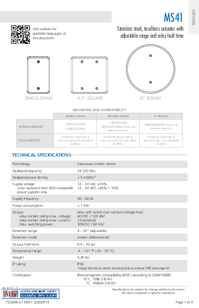
ENGLISH Visit website for available languages of this document. MS41 Stainless steel, touchless actuator with adjustable range and relay hold time SINGLE-GANG 4.5" SQUARE 6" ROUND SURFACE-MOUNT FLUSH-MOUNT MOUNTING BOX COMPATIBILITY SINGLE-GANG DOUBLE-GANG 10BOX24SGSM 10ABOXSGSMS 10BOXDGSM 10BOX475SQSM (must use adapter bracket) standard, single-gang electrical box (not provided by BEA) standard, double-gang electrical box (not provided by BEA) 6" ROUND 10BOX6RNDSM (must use adapter bracket) standard, single-gang electrical box (not provided by BEA) TECHNICAL SPECIFICATIONS Technology: microwave motion sensor Radiated frequency: 24.125 GHz Radiated power density: < 5 mW/cm2 Supply voltage: 12 24 VAC ±10% to be operated from SELV-compatible 12 24 VDC +30% / -10% power supplies only Supply frequency: 50 60 Hz Power consumption: < 1.5W Output relay contact rating (max. voltage): relay contact rating (max. current): Max. switching power: relay with switch-over contact (voltage-free) 60 VDC / 125 VAC 1A (resistive) 30W DC / 60 VAC Detection range: 4 24" (adjustable) Detection mode: motion (bidirectional) Output hold time: 0.5 30 sec Temperature range: -4 131 °F (-20 55 °C) Weight: 0.34 lbs IP rating: IP55 *Apply silicone to sensor housing base to achieve IP65 (see page 4)* Certification: Electromagnetic compatibility (EMC) according to 2004/108/EC FCC: G9B-210161 IC: 4680A-210161 Specifications are subject to change without prior notice. All values measured in specific conditions. 75.5996.01 MS41 20200714 Page 1 of 4 PRECAUTIONS Shut off all power going to header before attempting any wiring procedures. Maintain a clean and safe environment when working in public areas. Constantly be aware of pedestrian traffic around the door area. Always stop pedestrian traffic through the doorway when performing tests that may result in unexpected reactions by the door. ESD (electrostatic discharge): Circuit boards are vulnerable to damage by electrostatic discharge. Before handling any board, ensure you dissipate your body's ESD charge. Always check placement of all wiring before powering up to ensure that moving door parts will not catch any wires and cause damage to equipment. Ensure compliance with all applicable safety standards (i.e. ANSI A156.10) upon completion of installation. DO NOT attempt any internal repair of the components. All repairs and/or component replacements must be performed by BEA, Inc. Unauthorized disassembly or repair: 1. May jeopardize personal safety and may expose one to the risk of electrical shock. 2. May adversely affect the safe and reliable performance of the product resulting in a voided warranty. INSTALLATION TIPS 9 When wiring multiple devices together to create a system configuration, it is best to ensure that each device works independently. This will reduce troubleshooting if a discrepancy occurs. 9 Prior to installing any equipment in either new or existing circuits, verify correct line voltage and line stability. Always remember to shut off the power before performing circuit wiring. 9 Do not place the sensor in the door's opening range, where the sensor may see door movement. 9 Do not place moving objects in front of the sensor. 1 REMOVE FACE PLATE Detach the face plate from the cube by inserting a flathead screwdriver into one of the snap fittings and twisting to loosen from the face plate (see image below). Repeat on the nearby snap fitting located on the same side, top or bottom. You may loosen the cube from the plate on either the top or bottom. Only two snap fittings must be loosened. 2 WIRING Wire the MS41 to the door control according to the diagram shown here. NOTE: Use either N.O. or N.C. not both. Refer to the door control manual to determine which must be used. Page 2 of 4 12 24 VAC/VDC 12 24 VAC/VDC COM N.O. N.C. empty 75.5996.01 MS41 20200714 2 WIRING (cont.) RETROFIT APPLICATION You can retrofit hardwired push plates using the 900 MHZ Touchless Retrofit Transmitter (10TD900TR) and Receiver (10RD900): 1. Locate existing 2 wires previously used for the hardwired, mechanical push plate and connect to the MS41 terminals marked 12 24 VAC/VDC. 2. Wire to the 900 MHZ Touchless Retrofit Transmitter's power wires (red and black) with the two MS41 power wires. 3. At the door control, move the 2 wires from the push plate activation circuit to power (refer to Technical Specifications for power information). 4. Wire the 900 MHZ Receiver output to the door control activation circuit and its power wires shown in step 3 above. 3 SET-UP Six adjustments can be made to the sensor: 234 1 LED color+logic: DIP bank 1 determines LED color (see table) 1 DIP1 DIP2 DIP3 DETECTION NO DETECTION blue off off blue 5 blue blue green off off green 6 green green blue green green blue 2 Output Mode switch: determines Toggle mode or Timer mode = Toggle (detection activates the relay and the relay holds until a second detection deactivates the relay (recommended for switch applications) = Timer (detection activates the relay for 0.5 to 30 seconds; relay will hold as long as detection occurs) 3 LED activity (when illuminated): = animated (movement around track) = standard (on, static) 4 Buzzer sound (when in detection): = on = off 5 Hold time potentiometer: adjust relay hold time from 0.5 to 30 seconds (rotate clockwise to increase) 6 Sensitivity potentiometer: adjust detection field from 4 to 24 inches (rotate clockwise to increase) 75.5996.01 MS41 20200714 Page 3 of 4 4 INSTALLATION 1. Install an electrical box. If using a metal eletrical box, ensure that the sensor and related wiring does not come in contact with the box to avoid shorting the unit. 2. Clip the MS41 cube to the face plate. If IP65 rating is desired, apply silicone between the MS41 cube and face plate prior to installing the MS41 onto electrical box. 3. Secure the face plate to the electrical box with the provided screws. electrical box (metal/plastic) MS41 assembly Door does not open when swiping hand in front of sensor Sensor stays in detection Door remains open after detection/activation TROUBLESHOOTING Bad or no power Detection range too short Incorrect wiring/connection Check power supply, ensure SELVequivalent power. If LED switches on or flashes, power connections are okay. Adjust detection zone. Remove any metal plates in front of sensor. Check wiring and relay connection. Environmental conditions influencing sensor Wrong output mode Remove moving objects from around sensor. Switch output mode to Timer. Wrong output mode Switch output mode to Timer. Incorrect wiring/connection Check wiring and relay connection. FCC APPROVAL This device complies with Part 15 of the FCC Rules and with RSS-210 of Industry Canada. Operation is subject to the following two conditions: *this device may not cause harmful interference, and *this device must accept any interference received, including interference that may cause undesired operation. This equipment has been tested and found to comply with the limits for a Class B digital device, pursuant to part 15 of the FCC Rules. These limits are designed to provide reasonable protection against harmful interference in a residential installation. This equipment generates, uses and can radiate radio frequency energy and, if not installed and used in accordance with the instructions, may cause harmful interference to radio communications. However, there is no guarantee that interference will not occur in a particular installation. If this equipment does cause harmful interference to radio or television reception, which can be determined by turning the equipment off and on, the user is encouraged to try to correct the interference by one or more of the following measures: *Reorient or relocate the receiving antenna *Increase the separation between the equipment and receiver *Connect the equipment into an outlet on a circuit different from that to which the receiver is connected *Consult the dealer or an experienced radion/TV technician for help WARNING: CHANGES OR MODIFICATIONS TO THIS EQUIPMENT NOT EXPRESSLY APPROVED BY BEA INC. MAY VOID THE FCC AUTHORIZATION TO OPERATE THIS EQUIPMENT. BEA, INC. INSTALLATION/SERVICE COMPLIANCE EXPECTATIONS BEA, Inc., the sensor manufacturer, cannot be held responsible for incorrect installations or inappropriate adjustments of the sensor/device; therefore, BEA, Inc. does not guarantee any use of the sensor outside of its intended purpose. BEA, Inc. strongly recommends that installation and service technicians be AAADM-certified for pedestrian doors, IDA-certified for doors/gates, and factory-trained for the type of door/gate system. Installers and service personnel are responsible for executing a risk assessment following each installation/service performed, ensuring that the sensor system installation is compliant with local, national, and international regulations, codes, and standards. Once installation or service work is complete, a safety inspection of the door/gate shall be performed per the door/gate manufacturer recommendations and/or per AAADM/ANSI/DASMA guidelines (where applicable) for best industry practices. Safety inspections must be performed during each service call examples of these safety inspections can be found on an AAADM safety information label (e.g. ANSI/DASMA 102, ANSI/DASMA 107). Verify that all appropriate industry signage and warning labels are in place. ©BEA | Original Instructions | PLEASE KEEP FOR FURTHER USE - DESIGNED FOR COLOR PRINTING Page 4 of 4 Tech Support & Customer Service: 1-800-523-2462 General Tech Questions: techservices-us@BEAsensors.com | Tech Docs: www.BEAsensors.com 75.5996.01 MS41 20200714Adobe InDesign 15.1 (Macintosh) Adobe PDF Library 15.0