Getting Started with your Emporia Vue
Step 1: What's in the box
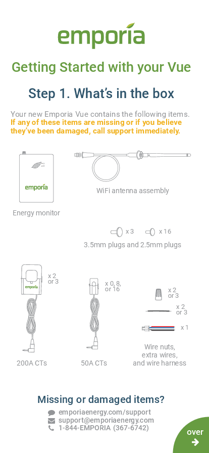
Your new Emporia Vue contains the following items. If any of these items are missing or if you believe they've been damaged, call support immediately.
- Energy monitor: A rectangular device with the Emporia logo and a leaf design.
- WiFi antenna assembly: A cable with a connector and an antenna.
- 3.5mm plugs and 2.5mm plugs: Small cylindrical insulation plugs.
- 200A CTs: Two or three current transformers (CTs) with 3.5mm audio jacks. Each CT is a clamp with wires.
- 50A CTs: Up to sixteen current transformers (CTs) with 2.5mm audio jacks. Each CT is a clamp with wires.
- Wire nuts, extra wires, and wire harness: Connectors and cables for electrical connections.
Step 2: Get the App
The easy-to-follow installation instructions are in the app! Download the Emporia Energy app onto your phone or tablet from the Apple App Store, from Google Play, or from emporiaenergy.com/app. Create an account and begin the setup process.
You can check your Wi-Fi signal strength next to the electrical panel in your home. Low/no signal may require a Wi-Fi extender for the Vue to work.
Download links:
More information and printable PDFs are available at: emporiaenergy.com/app and emporiaenergy.com/installation-guides.
Common Questions
- 200A CT orientation: The K→L imprint on the CT should point towards the breakers.
- 50A CT orientation: The K→L imprint on the CT should point towards the load.
- Dual-pole breakers: If monitoring a dual-pole breaker, connect the CT to only one lead and use a circuit multiplier in the app.
- Wire colors: Wire colors may not match your system. The general guide is: Black for Power & Phase 1 Voltage, Red for Phase 2 Voltage or Neutral, Blue for Phase 3 Voltage or Neutral, and White for Neutral.
Installation Guide
The Emporia Vue is a Smart Home Energy Monitor designed for field installation in a switch enclosure. It is considered a non-invasive load monitor (NILM) and a non-permanent fixture, acceptable for installation in an electrical panel.
WARNING! Safety Precautions
The Emporia Vue requires installing transformers inside your home's electrical panel and working around dangerous voltage that could lead to injury or death. Emporia recommends that installation be performed by a skilled person such as a licensed electrician or other qualified professional in accordance with the regional electrical code where it is being installed.
Improper installation or use of the equipment can be dangerous or even fatal. Emporia shall not be liable for any damages, direct or indirect, arising from personal injury due to failure to follow safety information and instructions.
Note: The 3.5mm and 2.5mm ports are exclusively for connecting the supplied CT clamps to the energy monitor and are not intended for audio signals. (French: Remarque: les ports 3,5 mm et 2,5 mm ne doivent être utilisés que pour connecter les pinces CT fournies au moniteur d'énergie. Ils ne sont pas destinés à transporter un signal audio.)
Safety Information
- Personal protective gear should be worn when installing the Emporia Vue.
- Do not use the Emporia Vue in any manner other than specified in this installation guide.
- Do not attempt to open, disassemble, or repair any components.
- If any components appear damaged, do not use them.
- Do not install in environments with explosive gas or vapors, damp or wet environments, direct sunlight, or temperatures consistently below -40°F (-40°C) or above 122°F (50°C).
- Ensure the Emporia Vue has no power during any handling, including installation and disassembly.
Before You Get Started
The Emporia Vue is installed in your home's electrical panel. You will turn off the main breaker, which shuts off all power in your home. However, the service mains will remain dangerously energized.
The following items may help with safe installation. It's also helpful to perform the installation with a friend:
- Phillips and flathead screwdrivers
- Protective eyewear
- Protective gloves
- Alternative light source
Installation Steps
Step 1: Turn off the main breaker and remove the cover
In your electric panel, turn off the main breaker (it may be located elsewhere). This turns off all circuits in your home. Next, remove any screws holding the cover to the panel to access the circuit breakers and the live service mains!
Diagram: An electrical panel with the main breaker shown in the 'OFF' position.
Step 2: Find a place for the monitor
Locate a place within your electrical panel for your Vue energy monitor. Your breaker box may be oriented differently, but the monitor is small and designed to fit easily. Find a place that works for you.
Diagram: An electrical panel with the Emporia Vue monitor placed inside. Text overlay: WARNING: The service mains are always live! ⚡
Live service mains are indicated.
Step 3: Mount the antenna
Screw the antenna assembly cable to the top of the energy monitor in the jack marked [WiFi symbol]. Slide the cable sleeve over the metal connection so it is fully insulated. Use a screwdriver to remove a knockout from inside the electrical panel. Feed the antenna through the hole. Plug the hole with the knockout plug. The antenna can be installed inside a wall.
Diagram: Shows the antenna connection to the monitor and feeding through a panel knockout.
Step 4: Plug in and connect the 200A current transformers
Your system will have 1, 2, or 3 main service cables. Open the clasps on the CTs and place each clamp around one of the main service cables. Then, shut the clasps to secure the CTs.
IMPORTANT! The K→L imprint on the bottom of the CTs should point toward the breakers.
Finally, insert the 200A current transformer audio jacks into the audio jack ports on the top of the energy monitor.
Diagram: Shows CTs clamped around service cables and plugged into the monitor's top ports. Text overlay: WARNING: The service mains are always live! ⚡
Step 5: Insulate empty 3.5mm 200A CT audio jack ports
Identify the empty 3.5mm 200A CT ports on the top of your Vue, labeled A, B, and C. Depending on your installation, you may have anywhere from 3 empty ports to none. If you have empty ports, securely insert the provided 3.5mm insulation plugs into all of them so they are completely insulated.
Diagram: Close-up of the monitor's top ports showing insulation plugs being inserted into empty jacks.
Step 6: Plug in the wire harness
Insert the power supply wiring harness into the bottom of the energy monitor until it clicks securely. The wire harness allows for single-phase power and three-phase voltage sensing:
- White wire connects to Neutral.
- Black wire provides power and voltage sensing.
- Blue and Red wires enable voltage sensing only.
Diagram: Shows the wire harness being plugged into the monitor's bottom port, with wires colored White, Black, Blue, Red.
Step 7: Wire the wire harness to a breaker and neutral bus
The wire harness connection depends on the number of empty 15A breakers and 200A CTs installed. Refer to the appropriate sub-step for your system. If unsure, contact Emporia Support.
- Step 8(a) Common in N. American homes: Two empty breakers, Two 200A CTs.
- Step 8(b) Common in N. American homes: No empty breaker, Two 200A CTs.
- Step 8(c) Common in European 3-phase homes / Uncommon in N. American homes / Common in N. American Commercial systems: Three empty breakers, Three 200A CTs.
- Step 8(d) Common in European 3-phase homes / Uncommon in N. American homes / Common in N. American Commercial systems: No empty breaker, Three 200A CTs.
- Step 8(e) Common in European 1-phase homes / Uncommon in N. American homes: One empty breaker, One 200A CT.
- Step 8(f) Common in European 1-phase homes / Uncommon in N. American homes: No empty breaker, One 200A CT.
Step 8(a): Two empty breakers and two 200A CTs
Secure the White and Blue wires from the wire harness to the neutral bus bar. Turn off two vertically adjacent (stacked) single pole 15A breakers and secure the Black and Red wires from the harness to each of the hot leads from each breaker.
Diagram: Shows the wiring connections within the panel for this configuration.
Step 8(b): No empty breaker and two 200A CTs
Secure the White and Blue wires from the wire harness to the neutral bus bar. Turn off two vertically adjacent (stacked) 15A single pole breakers and remove their wires. Connect one breaker wire to the Black harness wire and an extra wire using a wire nut. Connect the second breaker wire to the Red harness wire and an extra wire using a wire nut. Then secure each of the extra wires to the two breaker poles.
Diagram: Shows the wiring connections using extra wires and wire nuts for this configuration.
Step 8(c): Three empty breakers and three 200A CTs
Secure the White wire from the wire harness to the neutral bus bar. Turn off three vertically adjacent (stacked) 15A single pole breakers and secure the Black, Red, and Blue wires from the harness to each of the hot leads from each breaker.
Diagram: Shows the wiring connections within the panel for this configuration.
Step 8(d): No empty breaker and three 200A CTs
Secure the White wire from the wire harness to the neutral bus bar. Turn off three vertically adjacent (stacked) 15A single pole breakers and remove their wires. Connect one breaker wire to the Black harness wire and an extra wire using a wire nut. Connect the second breaker wire to the Red harness wire and an extra wire using a wire nut. Connect the third breaker wire to the Blue harness wire and an extra wire using a wire nut. Then secure each of the extra wires to the three breaker poles.
Diagram: Shows the wiring connections using extra wires and wire nuts for this configuration.
Step 8(e): One empty breaker and one 200A CT
Secure the Red, White, and Blue wires from the wiring harness to the neutral bus bar (use a wire nut and extra wire if needed). Turn off an empty 15A breaker and secure the Black wire from the harness to the hot lead from the breaker.
Diagram: Shows the wiring connections for this configuration.
Step 8(f): No empty breaker and one 200A CT
Secure the Red, White, and Blue wires from the wire harness to the neutral bus bar. Turn off a 15A breaker and disconnect its wire. Connect that wire to the Black wire from the harness and the piece of extra wire using a wire nut. Then secure the extra wire to the breaker.
Diagram: Shows the wiring connections using an extra wire and wire nut for this configuration.
Step 9: Plug in and connect the 50A current transformers
If your Vue has 50A CTs, open the clasps on the 50A CTs and place each clamp around the hot leg from the breaker you wish to monitor. Then shut the clasps to secure the CTs.
IMPORTANT! The K→L imprint on the bottom of the CTs should point away from the breakers.
Then, insert the audio jacks attached to them into the 2.5mm audio jack ports on the sides of the energy monitor. Note the port numbers so you can name the circuits in the app.
Diagram: Shows 50A CTs clamped to breakers and plugged into the monitor's side ports. Text overlay: WARNING: The service mains are always live! ⚡
Step 9 (continued): A note about multi-pole breakers
If you wish to monitor 2- or 3-pole breakers, you can use one CT on each pole, or a single CT. To use a single CT, clasp the clamp around either one of the hot leads coming off the breaker (it doesn't matter which). You can then input a circuit multiplier in the app (e.g., "2" or "3") to double or triple the reading. Emporia does not recommend multipliers for unbalanced loads, such as subpanels.
Diagram: Shows connecting a CT to only one lead of a multi-pole breaker.
Step 10: Insulate empty 2.5mm 50A CT audio jack ports
Identify the empty 2.5mm 50A CT audio jack ports on the sides of your Vue, labeled 1 through 16. Depending on your installation, you may have anywhere from 16 empty ports to none. If you don't have any empty ports, proceed to Step 11. If you do, securely insert the provided 2.5mm insulation plugs into all of the Vue's empty 2.5mm ports so they are completely insulated.
Diagram: Shows insulation plugs being inserted into the side ports of the monitor.
Step 11: Take a photo of your system
Before replacing your panel cover, take photos of your installation in case you need to contact support.
Diagram: A placeholder icon representing a camera.
Diagram: An electrical panel showing completed wiring connections.
Step 12: Replace the cover and turn on all breakers
Secure the cover to the box with any screws removed in Step 2. Next, flip any breakers that were turned off during installation to restore power to the circuits in your home. You should hear a power-up tone from the Vue to confirm it has power. Then, close the panel. Once the panel cover is replaced, the antenna connector and audio jack ports on the Vue will not be accessible.
Diagram: An electrical panel with the main breaker shown in the 'ON' position.
Step 13: Complete setup
Tap the button in the app to indicate that you've installed your Emporia Vue and heard its power-up tone. Your phone will connect via Bluetooth to the system. Then, you will connect to a nearby Wi-Fi router. Make sure you have your Wi-Fi name and password.
Diagram: A smartphone displaying the Emporia logo leaf.
Troubleshooting Tips
The Emporia app is not finding my Vue after installation:
- Ensure the Vue has power: Check for a green power light and listen for a startup tone.
- Check the wire harness is secure and wired properly.
- Ensure the main breaker and the breaker powering the Vue are turned on.
- Ensure your phone can connect to the Vue: Check that your phone's Bluetooth is on. If using Android, turn on Location Services for proper Bluetooth scanning.
- Ensure the Vue's Wi-Fi antenna is installed properly: Check it's screwed into the monitor and is outside the electrical panel (inside a wall is acceptable, but not inside the metal box).
- Try power cycling the breaker connected to the Vue.
- Try restarting the Emporia App.
- Try rebooting your phone.
The Emporia Energy app isn't getting real-time data from the Emporia Vue:
- Ensure all current transformers are securely fastened around their respective cables in your electric panel.
- Check that the current transformers' audio jacks are securely plugged into the audio jack ports of the energy monitor.
Technical Details
Energy Monitor
- Power supply input: 100-240VAC 1Ø, 50/60Hz, 0.041A
- Fuse: 260VAC/0.3A (Fusible resistor: 10E, 1W, 5%, TH)
- Power usage: < 11 Watts
- Wi-Fi: 2.4 GHz 802.11b/g/n
- Operating conditions: -40° to 122°F (-40° to 50°C), 0-80% RH
200A Current Transformers
- Max current: 200A
- Cable length: 1 m
- Inside diameter: 26 mm
50A Current Transformers
- Max current: 50A
- Cable length: 1 m
- Inside diameter: 10 mm
The Vue energy monitor and current transformers are considered a system designed for field installation in a switch enclosure as per section 312.8(B) of the 2017 National Electrical Code (NEC) regarding Power Monitoring Equipment. The Vue is considered a non-invasive load monitor (NILM) and as a non-permanent fixture, it is acceptable to install in an electrical panel.
FCC Compliance: The Emporia Vue Smart Home Energy Monitor contains FCC ID: 2AS6P-EMCTV2. This device complies with part 15 of the FCC Rules. Operation is subject to two conditions: (1) this device may not cause harmful interference, and (2) this device must accept any interference received, including interference that may cause undesired operation. This equipment complies with FCC RF radiation exposure limits for an uncontrolled environment. Install and operate with a minimum distance of 20 cm between the radiator and your body.
Caution: Any changes or modifications not expressly approved by Emporia void the user's authority to operate the equipment.
Certifications: CULUS LISTED, I.T.E. Energy Monitor E506714.
Designed in Colorado, USA. Manufactured in India.
Need help?
? 1-844-EMPORIA (367-6742)
