Assembly Instructions: Jackpot Contemporary Low Loft Bed with Stairway
Introduction
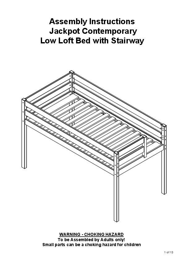
Thank you for your purchase from Maxwood Furniture. These assembly instructions are provided for future reference. This document outlines the assembly process for the Jackpot Contemporary Low Loft Bed with Stairway (Models 70615, 70616) and the associated Staircase & Side Rail unit (Model 70612).
Important Safety Information
⚠️ WARNING - CHOKING HAZARD
To be Assembled by Adults only! Small parts can be a choking hazard for children.
Safety is our number one concern. Please follow these simple safety tips:
- Remember to check and tighten bolts/hardware once every few months, as these may loosen with use over time.
- If you have purchased a bed, choose a low profile mattress for the top bunk (ideally 5" (13cm) or max 10" (25cm)) to maximize safety rail height.
- Make sure to anchor your large dressers to the wall with the free anti-tip kit provided. Read and follow the safety instructions on the card attached to the front of your dresser.
- Do not allow children under 6 years of age to use the upper bunk.
- Periodically check and ensure that the guardrail, ladder, and other components are in their proper position, free from damage, and that the connectors are tight.
- Do not allow horseplay on or under the bed and prohibit jumping on the bed.
- Prohibit more than one person on the upper bunk.
- Always use the ladder for entering and leaving the upper bunk.
- Do not use substitute parts. Contact the manufacturer or dealer for replacement parts.
- Use of a night light may provide added safety precaution for a child using the upper bunk.
- Always use guardrails on both long sides of the upper bunk.
- If the bunk bed will be placed next to a wall, the guardrail that runs the full length of the bed should be placed against the wall to prevent entrapment between the bed and the wall.
- The use of water or sleep flotation mattresses is prohibited.
- Keep these instructions for future reference.
RISQUE D'ÉTRANGLEMENT / STRANGULATION HAZARD
Never attach or hang items to any part of the bunk bed that are not designed for use with the bed, for example, but not limited to hooks, belts, and jump ropes.
Bed Frame Parts List (Models 70615 & 70616)
Components:
- 01 - Side Post (Left) - 2x
- 02 - Side Post (Right) - 2x
- 03 - Front/Back Rail - 4x
- 04 - Side Rail - 2x
- 05 - Support Rail - 1x
- 06 - Guard Rail (Short) - 4x
- 07 - Guard Rail (Long) - 2x
- 10 - Bed Slats - 1x (Set)
Hardware:
- 20009 (M8*110mm Bolt) - 36x
- 20359 (Ø8*17mm Nut/Cam Lock) - 36x
- 20055 (4*30mm Screw) - 28x
- 20343 (4*25mm Screw) - 3x
- 20056 (Ø10 x 40mm Dowel) - 24x
- 20033 (Ø10*10mm Dowel) - 12x
- 20015 (Hex Key / Allen Wrench) - 1x
Assembly Instructions - Bed Frame
Step 1: Prepare Side Rails
Insert 20056 dowels (16x) into the ends of 03 Front/Back Rails (4x). Insert 20056 dowels (8x) into the ends of 04 Side Rails (2x).
Step 2: Attach Side Rails to Posts
Connect 03 rails to 01 and 02 posts using 20009 bolts (36x) and 20359 nuts (36x). Use the 20015 hex key ? to tighten. Ensure the correct orientation as shown in diagrams, using dowels for alignment.
Step 3: Attach Support Rail
Attach 05 Support Rail to the assembled frame using 20009 bolts (6x) and 20359 nuts (6x).
Step 4: Attach Guard Rails
Attach 06 Guard Rails (4x) and 07 Guard Rails (2x) to the side posts using 20009 bolts (24x) and 20359 nuts (24x).
Step 5: Install Bed Slats
Place the 10 Bed Slats onto the support rails. Secure the slats using 20055 screws (28x) and 20343 screws (3x) into the designated holes on the side rails and support rails. Ensure correct orientation using the checkmark/cross symbols provided in the diagrams.
Step 6: Final Check
Verify all connections are secure. Ensure mattress height meets safety requirements (at least 5" (13cm) below the top of the guardrail).
Staircase & Side Rail Parts List (Model 70612)
Components:
- 01 - Drawer Side Panel - 3x
- 02 - Drawer Bottom Panel - 3x
- 03 - Drawer Front/Back Panel - 3x
- 04 - Outer Side Panel - 2x
- 05 - Drawer Base Support - 3x
- 06 - Outer Back Panel - 1x
- 07 - Outer Front Panel - 1x
- 08 - Main Side Panel (Left) - 1x
- 09 - Main Side Panel (Right) - 1x
- 10 - Drawer Front Panel - 3x
- 11 - Drawer Back Panel - 3x
- 12 - Drawer Bottom Support - 3x
- 13 - Drawer Base Panel - 3x
- 14 - Drawer Front Panel (Decorative) - 3x
- 15 - Stair Riser Panel - 1x
- 16 - Stair Tread Panel - 1x
- 17 - Stair Top Panel - 1x
- 18 - Back Panel - 1x
Hardware:
- 20336 (M6*60mm Bolt) - 4x
- 20409 (M6*50mm Bolt) - 3x
- 20141 (M6*35mm Bolt) - 52x
- 20125 (Hex Key / Allen Wrench) - 1x
- 20055 (4*30mm Screw) - 37x
- 20362 (4*20mm Screw) - 18x
- 20017 (Plate L) - 3x
Assembly Instructions - Staircase & Side Rail Unit
Step 1: Assemble Drawer Boxes
For each of the 3 drawer units: Attach 01 Drawer Side Panels (2x) to 03 Drawer Front/Back Panels (2x) using 20141 bolts (6x per unit) and 20125 hex key ?. Insert 02 Drawer Bottom Panel into the grooves. Attach 05 Drawer Base Supports using 20141 bolts (6x per unit).
Step 2: Assemble Drawer Fronts
Attach 10 Drawer Front Panels and 11 Drawer Back Panels to the assembled drawer boxes using 20055 screws (12x per unit). Attach 14 Decorative Drawer Front Panels using 20055 screws (12x per unit).
Step 3: Assemble Main Staircase Structure
Assemble the main structure by connecting 08 Main Side Panel (Left) and 09 Main Side Panel (Right) to 15 Stair Riser Panel, 16 Stair Tread Panel, and 17 Stair Top Panel using 20336 bolts (4x), 20409 bolts (3x), and 20141 bolts (52x). Use the 20125 hex key ?. Attach 18 Back Panel using 20055 screws (37x).
Step 4: Attach Drawer Units to Structure
Slide the assembled drawer units into their respective positions within the main staircase structure. Ensure they slide smoothly on the integrated runners.
Step 5: Secure Staircase Structure
Use 20362 screws (18x) and 20017 L-Plates (3x) to reinforce connections as shown in the diagrams.
Attaching Staircase Unit to Bed Frame
The Staircase & Side Rail unit (Model 70612) can be attached to either the left or right side of the bed frame. Follow the diagrams carefully to align the unit with the bed frame posts and secure it using the provided hardware (20055 screws, 20362 screws, and 20017 L-Plates).
The diagrams show specific attachment points and hardware for both left and right configurations. Pay close attention to the orientation of the staircase unit relative to the bed.
Final Notes & Support
For detailed mattress size recommendations, safety guidelines, and information on obtaining replacement parts, please refer to the general information section provided in English, French, and Spanish in the original documentation.
Visit the official website for more information:
