How To: Replace Paddle Wheel
This guide provides step-by-step instructions for replacing the paddle wheel in Baratza coffee grinders, including models Encore, Virtuoso, Preciso, Maestro, and Maestro Plus. The estimated time for this task is 15-30 minutes, with a difficulty level rated as Medium.
Tools and Supplies
- Part 1: Plate Vise Grips, Paperclip
- Part 2: Flat head screwdriver, Cloth, Philips screwdriver and/or T 10 Hex
- Parts: Paddle wheel (Part #6380 – Paddle wheel & felt)
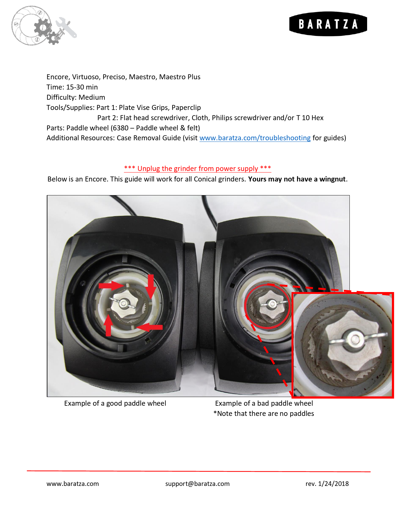
Important Safety Note: *** Unplug the grinder from power supply ***
This guide is applicable to all Conical grinders. The example shown is an Encore; other models may differ slightly, such as not having a wingnut.
Image Description: Two grinders are shown side-by-side. The left grinder displays a good paddle wheel with red arrows indicating its rotation. The right grinder shows a bad paddle wheel, with a magnified inset highlighting the condition. Captions read: "Example of a good paddle wheel" and "Example of a bad paddle wheel *Note that there are no paddles".
Technique 1 (Faster but More Difficult)
This method involves jolt-loosening the cone burr, which requires careful handling and tools, and success can depend on luck. If successful, it's a quick repair. If it fails after several attempts, proceed to the second method for a more systematic disassembly.
Rotate the wingnut off the grinder (specific to Encore models). The wingnut is reverse threaded, so turn it clockwise to loosen.
Image Description: A close-up view of the grinder's interior shows the wingnut. Red arrows indicate a clockwise rotation to loosen the wingnut.Clamp the cone burr securely with Plate Vise grips. Use your hand, a mallet, or a hammer to strike the Vise grips horizontally along the X-axis, causing the cone burr to rotate CLOCKWISE. The cone burr can turn in either direction; the impact should provide enough torque to break the burr free from the shaft. Once loosened, unscrew it by hand CLOCKWISE until it is removed.
Image Description: Vise grips are shown clamping the cone burr. A hand or mallet is depicted hitting the vise grips. A red arrow indicates the direction of rotation (clockwise).Continue to spin the burr clockwise until it fully releases from the drive shaft.
Image Description: Two views of the grinder interior. The left image shows the cone burr being spun clockwise, indicated by a red curved arrow. The right image shows the cone burr completely detached from the drive shaft.Use a pointed object, such as a paperclip or screwdriver, to carefully lift the old paddle wheel out of the grinder. Ensure the grinder is not turned upside down during this process.
Image Description: A pointed tool (like a paperclip or screwdriver) is used to lift the old paddle wheel from the grinder.After removing the paddle wheel, you will find a felt and shims remaining on the drive shaft. Do not remove these. Simply place the new paddle wheel and felt into the grinder.
Image Description: Two views of the grinder's drive shaft area after the paddle wheel has been removed, showing the remaining felt and shims.Reinsert the cone burr into the grinder and rotate it fully counter-clockwise until the burr is flush with the drive shaft. If the burr is not flush, it indicates that the male and female posts are misaligned. Use a pick tool to gently rotate the burr into the correct position.
Image Description: Two views of the grinder interior as the cone burr is being reinserted. The left shows the burr being rotated counter-clockwise. The right provides a close-up of the burr and drive shaft, with red arrows pointing to the alignment of the posts. A text box states: "If it is not flush, that means the male and female posts do not line up. Use a pick to rotate into position."Place the wingnut back onto the grinder. To tighten it, turn it counter-clockwise. Tighten until it stops; no further tightening is necessary as it will self-tighten as coffee passes through the grinder.
Image Description: A close-up view of the grinder interior shows the wingnut being reinstalled. Red arrows indicate the clockwise direction for tightening.
Technique 2 (Longer but Easier)
This alternative method involves accessing the grinder's gearbox to replace the paddle wheel.
Begin by unplugging the grinder and removing its outer case.
For Encore models, remove the wing nut (refer to Part 1, Step 1). Then, remove the adjustment ring. To do this, insert a screwdriver under the edge of the adjustment ring at approximately the 3, 7, and 11 o'clock positions and gently pry upwards. Pay close attention to the detent, as it is spring-loaded and could potentially dislodge.
Image Description: Three images illustrate the process of removing the adjustment ring. A screwdriver is used to pry the ring up at different points (3, 7, and 11 o'clock), indicated by red arrows. A small inset highlights the detent mechanism.Carefully remove the micro switch by lifting it off its two posts on the housing. Next, unhook the motor. Finally, remove the three screws that secure the gearbox to the housing assembly.
Image Description: Two images show the removal of the micro switch and motor. The micro switch is lifted off its posts, and the motor is unhooked, with red arrows indicating the directions of removal.Flip the housing upside down and remove the four screws that hold the motor to the housing.
Image Description: Two images depict the motor removal. The left shows the housing inverted, with red arrows pointing to the four screws securing the motor. The right image shows the motor being detached.Proceed to remove the nut and bolt from the drive shaft. The drive shaft and gear are prone to rotation during this step. To counteract this, wedge a cloth into the gearbox to provide the necessary resistance for loosening the nut.
Image Description: A cloth is shown wedged into the gearbox to provide resistance while a nut is being removed from the drive shaft.Use a soft tool, such as a rubber mallet or the handle of a screwdriver, to gently tap the main drive gear out of the gearbox. Avoid using a metal hammer, as this could damage the drive shaft. Place a hand underneath to support and prevent parts from falling or becoming damaged.
Image Description: A hand is shown using a rubber mallet or screwdriver handle to tap the main drive gear out of the gearbox.Remove the main drive gear. It is crucial to keep track of each washer and its original position within the grinder. Washers may vary in thickness, and reassembling them in their correct locations is important. Grinders may also have different shims. In the provided example, there are two washers located under the main drive gear and four under the paddle wheel/felt assembly.
Image Description: Two views display the removed main drive gear along with its associated washers and shims. Red arrows highlight the washers.Remove the old paddle wheel and install a new one that has four flanges. At this stage, reinsert the washers and felt onto the paddle wheel and then onto the drive shaft. Ensure that the female and male components of the paddle wheel and cone burr align correctly.
Image Description: Two images illustrate the installation of the new paddle wheel. The left shows the new paddle wheel with four flanges being placed onto the drive shaft, indicated by a red arrow. The right image displays the individual components: the new paddle wheel, felt, and washers.Place the washers previously removed from the main drive gear back onto the drive shaft. Then, reattach the main drive gear onto the shaft. Confirm that the hexagonal piece on the drive shaft properly seats into the gear. Using a weight or socket underneath can greatly assist in pushing the gear into place and reduce stress on the chassis.
Image Description: Two views show the drive shaft and gear assembly being reassembled. The left image shows the main drive gear being placed onto the shaft, with a red arrow indicating insertion. A weight or socket is positioned underneath for support. The right image offers a close-up of the hexagonal shaft fitting into the gear.Reattach the motor/plate assembly to the housing and secure it with all four screws.
Image Description: Two images illustrate the reattachment of the motor assembly. The left shows the motor/plate being secured with red arrows pointing to the four screws. The right depicts the motor assembly being placed back into the grinder housing, with red arrows indicating the placement.Turn the grinder back upright and place it onto the chassis. Reinstall the three screws to secure it. Ensure the micro switch is also placed back onto its posts.
Image Description: Two images show the final reassembly steps. The left displays the grinder chassis with the motor assembly in place, and red arrows point to the three screws for reattachment. The right shows the micro switch being positioned back onto its posts, with red arrows indicating the placement.Replace the adjustment ring by applying pressure evenly around it, starting at the 11 o'clock position, then moving to 3 and 7 o'clock. Keep a close watch on the detent, as it is spring-loaded and can dislodge. Aligning the cutout in the adjustment ring with the discharge chute will help the detent engage with the adjustment threads. Applying pressure by cupping the adjustment ring with your hand can also be effective. Finally, replace the wing nut (as described in Part 1, Step 7).
Image Description: Three images illustrate the reinstallation of the adjustment ring. The left shows pressure being applied at the 11 o'clock position. The middle shows pressure applied at 3 and 7 o'clock, with a red arrow indicating alignment over the discharge chute. The right image shows downward pressure being applied. A text box reads: "Push Down 1st".Place the grinder case back onto the unit.
Image Description: The grinder case is shown being placed back onto the main unit.
