Cuisinart SMK2036AS Oakmont Pellet Grill and Smoker Instruction Manual
File info: application/pdf · 21 pages · 1.61MB
OM SMK2036AS ASSY
User Manual
The Boltz Group, LLC SMK2036AS-HS Oakmont Pellet Grill 2AURUSMK2036AS-HS 2AURUSMK2036ASHS smk2036as hs
The Boltz Group, LLC SMK2036AS Oakmont Pellet Grill 2AURUSMK2036AS 2AURUSMK2036AS smk2036as
Full PDF Document

If the inline viewer fails, it will open the original document in compatibility mode automatically. You can also open the file directly.
Extracted Text
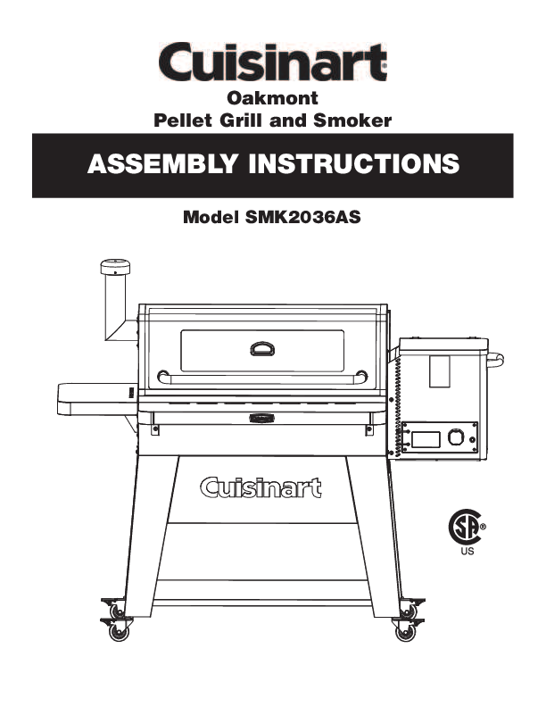
Oakmont Pellet Grill and Smoker
ASSEMBLY INSTRUCTIONS
Model SMK2036AS

ASSEMBLY INSTRUCTIONS:
READ ALL SAFETY WARNINGS & ASSEMBLY INSTRUCTIONS CAREFULLY BEFORE ASSEMBLING OR OPERATING YOUR GRILL.

WE RECOMMEND TWO PEOPLE WORK TOGETHER WHEN ASSEMBLING THIS UNIT.

The following tools are required to assemble this Cuisinart Oakmont 3-in-1 Pellet Grill:
� Phillips Screwdriver � Pliers or Wrench

PARTS LIST:

1 1 Side Table

2 1 Chimney

31 41 51

Hood Handle Warming Rack Rear Cart Brace

6 2 Right Table Brackets

7 2 Left Table Brackets

8 1 Grease Channel

91 10 1 11 2

Grill Body Thermocouple Assembly Side Cart Braces

12 1 Left Front Leg

13 1 Right Front Leg

14 1 15 1 16 1

Left Rear Leg Right Rear Leg Temperature Gauge Bezel

17 1 Temperature Gauge

18 4 Cooking Grates

19 1 20 1 21 4 22 1 23 1 24 1 25 1 26 1 27 1 28 1 29 1 30 1 31 1 32 2 33 1 34 1 35 1 36 1

Heat Plate Bracket Hopper Lid Casters Heat Plate Ash Clean-out Plate Ash Clean-out Handle Side Handle Cart Base Front Table Pellet Hopper Assembly Cord Wrap Cart Front Panel Grease Cup Bracket Ash Cup Brackets Heat Baffle Grease Cup Ash Cup Control Knob

Note: Most hardware is pre-attached to the grill. You may need to loosen some screws partially while others may need to be removed in order to assemble parts. The screws that you remove will be re-used so don't misplace this hardware.
Extra screws are included in a small bag with the owners manual.

1

1 2

5 7

6

8

11

13

15

16

12

14

17

21

4 3 9
18

10 19

26 30

31

32

22 27

20 24 23 25
29
28

33

34

36

35

2

Step 1

� Loosen 4 screws.

� Attach front legs 12 and 13 front panel 30 using keyholes.

� Tighten 4 screws. � Remove 8 screws.

Remove

12

30 13 Remove

NOTE: Before tightening keyhole screws, make sure panels are aligned.

Step 2

� Attach side cart braces

11 to front legs 12 and 13

using 4 screws removed

from Step 1.

11

12

11 13

3

12 26
5 14
Remove

Step 3
� Attach cart base 26 to front legs 12 and 13 using 4 screws removed from Step 1.
13
Step 4
� Remove 12 screws. � Attach rear cart brace
5 to rear legs( 14 and 15 ) using 4 screws just removed.
15

4

Step 5
� Attach side cart braces 11 to rear legs ( 14 and 15 ) using 4 screws removed from Step 4.

11 14
11 15

Step 6
� Attach cart base 26 to rear legs ( 14 and 15 ) using 4 screws removed from Step 4.
� Tighten all screws.
15 14
26
5

Step 7
� Lock casters 21 . � Attach casters 21 to legs.
21 CASTERS unlocked
locked

Step 8

17

� Attach temperature

16

gauge 17 and bezel 16 to

hood using pre-attached

washer and wing nut.

6

Step 9

� Loosen 2 rear screws and remove 2 front screws on both sides of grill body 9.

� Set grill body 9 on cart. Make sure rear screws drop into cart brackets.

� Install front screws

9

through front brackets.

� Tighten 4 screws.

Remove

Loosen

Step 10
� Remove 4 screws from grease cup bracket 31 .
� Attach grease cup bracket 31 to bottom of firebox using 4 screws just removed.
31
7

Step 11
� Remove 4 screws from ash cup brackets 32 .
� Attach ash cup brackets 32 to bottom of firebox using 4 screws just removed.
32
Step 12
� Install ash cup 35 and grease cup 34 .

35

34

8

Step 13
� Remove 2 screws. � Attach grease channel
8. � Tighten 2 screws.
8

Step 14
� Attach control knob 36 to the controller located on the pellet hopper assembly 28.
9

28 36

28 Light Wires
23
23

Step 15
� Install pellet hopper assembly 28 into grill body.
� Attach pellet hopper assembly 28 to grill body using 4 screws. (These screws are in the bag with the owner's manual.)
� Tighten 4 screws. Note: When assembling the pellet hopper to the grill, the light wires should be fed through the back side of the pellet hopper to ensure there is enough wire to connect during Step 29b.
Step 16
� Remove 2 screws from ash clean-out plate 23 and set aside for later use.
� Slide ash clean-out plate 23 into bottom of auger housing.
10

Step 17
� Insert ash clean-out handle 24 through back of grill body.
� Attach ash clean-out handle 24 to ash cleanout panel 23 using 2 screws removed from Step 16.
24
Step 18
� Remove 3 screws. � Attach heat plate bracket
19 using 3 screws just removed.
19
11

Step 19

� Remove 1 screw from heat baffle 33 .

� Insert the heat baffle

33

pin into auger box and tighten screw to hold in

place.

Thermocouple Wire

Step 20

� Remove 2 screws.

� Attach thermocouple assembly 10 using 2 screws just removed.

Note: Make sure to feed

the thermocouple wire

on the back side of the

auger box to ensure there

is enough wire to connect

10

during Step 29b.

12

Step 21
� Attach side handle 25 using 2 pre-attached screws from side handle.
25
Step 22
� Remove 8 screws. � Attach hopper lid 20 to
pellet hopper body using 8 screws just removed.
20
13

29 2

Step 23
� Remove 2 screws. � Attach cord wrap 29
using 2 screws just removed.
Step 24
� Remove 5 screws. � Attach chimney 2 using
5 screws just removed.
14

Step 25

� Install hood handle 3

using screws and bezels

3

pre-installed on handle.

Step 26

� Remove 4 shoulder bolts from left and right table brackets 7 and 6 .

� Attach left and right table

brackets 7 and 6 to

side table 1 and front

table 27 using shoulder

7

bolts just removed.

1 6
27

7

6

15

Step 27
� Remove 4 screws from grill body.
� Attach side table 1 to grill body using 4 screws just removed.
1
Step 28
� Remove 4 screws from grill body.
� Attach front table 27 using 4 screws just removed.
27
16

Step 29a
� Remove 1 screw from the bottom of pellet hopper panel.

Step 29b
� Connect the thermocouple connector and the two 10 watt light connectors. These wires can only be connected one way.
Note: All connectors must be connected in order for the grill to function properly.
Step 29c
� Close pellet hopper bottom panel and secure with screw.

Thermocouple Connector
10 watt Light Connectors

17

Step 30

� Place heat plate 22 inside cooking chamber on brackets.

Note: The heat plate

should set in the grease

channel and the heat

plate bracket. Once

installed the heat plate

will slope down to the left

to ensure grease flows

22

into the grease cup.

Step 31
� Place 4 cooking grates 18 inside cooking chamber.
18

18

Step 33
� Place the warming rack 4 on supports inside cooking chamber.
4
19

Model SMK2036AS Assembled

OM2036AS/ASO 0921

�2021 The Boltz Group LLC. Carrollton, Texas 75006 U.S.A.

Assembly Instructions for Model SMK2036AS