LINAK CO71 Control Box with Bluetooth User Manual
File info: application/pdf · 35 pages · 5.80MB
user manual 4
LINAK A/S COL50 Bluetooth Control Box XBE-COL50 XBECOL50 col50
Full PDF Document

If the inline viewer fails, it will open the original document in compatibility mode automatically. You can also open the file directly.
Extracted Text
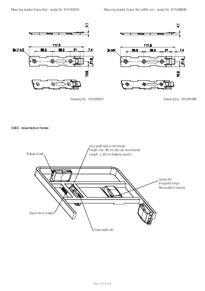
Mounting bracket (frame flat) - article No . 1015W1001:

Mounting bracket (frame flat) w/M4 nuts - article No . 1015W9009:

Drawing No .: 1015W4001

Drawing No .: 1015W4009

CO65 - mounted on frame: Release hook
Easy-mount bracket

Very small built-in dimension: Height: min . 80 mm (lid can be removed) Length: + 20 mm (locking system)
Service lid Integrated hinge Removable if needed
3-way cable exit

Page 129 of 264

Mounting instructions (Example CO65 with LA40) When mounting the control box onto the actuator (1)
Simply slide on the bracket until you hear a clear click (2)
Slide on the control box until you hear a click and the box is mounted (3)
It is recommended that the CO65 is mounted in a position that allows water to escape . Recommended torque: 0 .6 Nm +/-0 .1 The bracket can be mounted to the bed frame or any other application by following one of the following mounting procedures: 1) M6 nut to be placed in bracket and fixed with M6 bolt from the rear side . 2) M5 machine screw with flat washer to be fixed through bracket with nut on the rear side . 3) Self-tapping screw to be placed through bracket and onto the frame .
Page 130 of 264

Mounting of cables and cable lock: CO65 has a uniquely designed cable lid . The lid also works as an integrated cable lock when closed . 1) Mount cable plugs in control box 2) Close lid until lock snaps into place (see arrows) To allow free access to the cables, the lid has a rest position when completely opened . It is possible to remove the lid by lifting it a few degrees and pulling it away from the housing under tight mounting conditions . See illustrations:
1
Cable management: 2
Page 131 of 264

Recommendations � To avoid unintended activation of actuators if hand control cables short-circuit, LINAK recommends to use an OpenBus system (CO65) . � If there is a risk that the system is overloaded and therefore shuts down thermally, LINAK recommends to use quick release actuators . These will allow
functions to be lowered manually in case of a CO65 malfunction due to misuse/abuse . � If the customer has other essential performance than "no unintended movement", he must consider this in his own risk analysis . LINAK disclaims
any liability . � If the actuator or the control cable is removed from the control box, the cable lock must be applied . To ensure movement in this case, LINAK
recommends to use quick release actuators in the application . � To avoid cables from being damaged by pulling, LINAK recommends to make safe cabling . If movement is an essential performance, LINAK
recommends to apply quick release actuators, for example, to ensure movement . � To avoid thermal protection from being activated, do not exceed load specifications . If movement is an essential performance, LINAK recommends
to apply quick release actuators, for example, to ensure movement . � Sales must request a review of the products according to current cut-off limits . � Push plugs fully into correct sockets . Make sure that the plugs are completely inserted . � Mount control box lid and close lid until locked in place .
Motor cable Always use 6-wire cables . Please note that angled motor cable plugs are required for connection to the control box .
Warnings � Use EPR or ensure that the user takes care not to squeeze the mains cable . � Always check correct assembly after mounting and service to ensure that the cable lock is mounted . (Connectors are usually removed during cleaning) � Always use approved chemicals with the housing as the plastic may show corrosion caused by some chemicals . As a result water may accumulate/
gather in housing . � Take special precautions concerning 3rd party interfacing . Please contact LINAK for further information . � Make a review of all product specifications before system set-up if the current cut-off limit is higher than the maximum allowed current cut-off for
the actuator . � To avoid cable interruption and actuator defects make a proper cable installation and inspect regularly for wear and damage . Defective parts must
be replaced . � After service inspection, the application must be tested for correct functionality before it is put into operation to avoid actuator plugs being mixed
during service . Operators must not be inside entrapment area . � To avoid electrical failure or system disturbance inspect regularly for wear and damage . Defective parts must be replaced . � Make a proper cable installation to avoid short-circuit cables for handset/controls . Regular inspection must be made for wear and damage . Defective
parts must be replaced . � Do not mount the actuator with the spindle facing downwards to avoid that the actuator slips off the bracket with mounted control box . The bracket
can come loose when exposed to shock or hard vibratio, for instance when passing doorsteps . Regular inspection must be made to ensure proper fixation of control box and bracket on actuator .
Page 132 of 264

15. CO71 (MEDLINE� CARELINE� )

The LINAK control box CO71 offers a consolidated range of unprecedented features � all utilising standardised technology, interfaces and compatibility . The CO71 for LINAK actuators is intended for the control of, for example, hospital bed movement . Equipped with 350W SMPS, excellent and well thought-out cable management as well as multiple easy mounting options, this control box opens up a wide range of application possibilities for the provident hospital and care products manufacturer .
Features and Options: � Duty cycle: 10 % - 2/18 min . on/off continuous use .
Maximum power is 350 W for 80 seconds and 175 W for 40 seconds at 25 �C .

LED indicator

CO71 is equipped with a green LED for indication of mains power connected . When the CO71 is connected to mains, the LED is green . Connected only to battery, the LED is off .

Connected to MAINS

LED colour Indication of operation

Green

On mains, not activated by hand or foot control. The system is working ok and is ready for normal operation .

Yellow

On mains, not activated by hand or foot control. The system is defective and should not be operated .

Yellow

On mains, activated by hand or foot control. The system is working .

Not connected to mains but with BATTERY back-up

LED colour Indication of operation

Orange

On battery, activated by hand or foot control. The system is working .

No LED

On battery, not activated by hand or foot control. or CO71 not connected to mains .

Acoustic signal functionality: The buzzer will make a warning, when a button on the hand control is pressed, and the battery state of charge is low . The buzzer can also be activated by the control box to signal other conditions . This must be specified in the control box software .

Page 133 of 264

Mounting bracket (frame flat) - article No . 1015W1001:

Mounting bracket (frame flat) w/M4 nuts - article No . 1015W9009:

Drawing No .: 1015W4001

Drawing No .: 1015W4009

CO71 - mounted on frame: Release hook
Easy-mount bracket

Very small built-in dimension: Height: min . 80 mm (lid can be removed) Length: + 20 mm (locking system)
Service lid Integrated hinge Removable if needed
3-way cable exit

Page 134 of 264

Mounting instructions (Example CO71 with LA40) When mounting the control box onto the actuator (1)
Simply slide on the bracket until you hear a clear click (2)
Slide on the control box until you hear a click and the box is mounted (3)
It is recommended that the CO71 is mounted in a position that allows water to escape . Recommended torque: 0 .6 Nm +/-0 .1 The bracket can be mounted to the bed frame or any other application by following one of the following mounting procedures: 1) M6 nut to be placed in bracket and fixed with M6 bolt from the rear side . 2) M5 machine screw with flat washer to be fixed through bracket with nut on the rear side . 3) Self-tapping screw to be placed through bracket and onto the frame .
Page 135 of 264

Mounting of cables and cable lock: CO71 has a uniquely designed cable lid . The lid also works as an integrated cable lock when closed . 1) Mount cable plugs in control box 2) Close lid until lock snaps into place (see arrows) To allow free access to the cables, the lid has a rest position when completely opened . It is possible to remove the lid by lifting it a few degrees and pulling it away from the housing under tight mounting conditions . See illustrations:
1
Cable management: 2
Page 136 of 264

Recommendations � To avoid unintended activation of actuators if hand control cables short-circuit, LINAK recommends to use an OpenBusTM system (CO71) . � If there is a risk that the system is overloaded and therefore shuts down thermally, LINAK recommends to use quick release actuators . These will allow
functions to be lowered manually in case of a CO71 malfunction due to misuse/abuse . � If the customer has other essential performance than "no unintended movement", he must consider this in his own risk analysis . LINAK disclaims
any liability . � If the actuator or the control cable is removed from the control box, the cable lock must be applied . To ensure movement in this case, LINAK
recommends to use quick release actuators in the application . � To avoid cables from being damaged by pulling, LINAK recommends to make safe cabling . If movement is an essential performance, LINAK
recommends to apply quick release actuators, for example, to ensure movement . � To avoid thermal protection from being activated, do not exceed load specifications . If movement is an essential performance, LINAK recommends
to apply quick release actuators, for example, to ensure movement . � Sales must request a review of the products according to current cut-off limits . � Push plugs fully into correct sockets and make sure that the plugs are completely inserted . � Mount control box lid and close lid until locked in place .
Motor cable Always use 6-wire cables . Please note that angled motor cable plugs are required for connection to the control box .
Warnings � Use EPR or ensure that the user takes care not to squeeze the mains cable . � Always check correct assembly after mounting and service to ensure that the cable lock is mounted . (Connectors are usually removed during cleaning) � Always use approved chemicals with the housing as the plastic may show corrosion caused by some chemicals . As a result water may accumulate/gather
in housing . � Take special precautions concerning 3rd party interfacing . Please contact LINAK for further information . � Make a review of all product specifications before system set-up if the current cut-off limit is higher than the maximum allowed current cut-off for the
actuator . � To avoid cable interruption and actuator defects make a proper cable installation and inspect regularly for wear and damage . Defective parts must be
replaced . � After service inspection, the application must be tested for correct functionality before it is put into operation to avoid actuator plugs being mixed during
service . Operators must not be inside entrapment area . � To avoid electrical failure or system disturbance inspect regularly for wear and damage . Defective parts must be replaced . � Make a proper cable installation to avoid short-circuit cables for hand control/controls . Regular inspection must be made for wear and damage . Defective
parts must be replaced . � Loss of mains: If the power supply is switched off for a short time (between 1 and approx . 1 .5 seconds), the control box will only start up again if
a key is pressed . This is only relevant for OpenBusTM systems that run continually � Do not mount the actuator with the spindle facing downwards to avoid that the actuator slips off the bracket with mounted control box . The bracket can
come loose when exposed to shock or hard vibration, for instance when passing doorsteps . Regular inspection must be made to ensure proper fixation of control box and bracket on actuator .
Page 137 of 264

16. OPS - OpenBus Power Supply (MEDLINE� CARELINE� )
The LINAK OpenBus Power Supply (OPS) is intended to control up to three heat pads . The OPS is equipped with 120 W constant power and comes as IPX6 Washable DURATM . The OPS offers flexible system combinations and can be used as a stand-alone system or as add-on to the existing LINAK CO control box solution as CO-LinkTM .

Usage: � Duty cycle: � Operation temperature: � Storage temperature: � Relative humidity: � Atmospheric pressure: � Height above sea level: � Flammability rating: � Latex free: � Approvals:

100% +5 �C to + 40 �C -10 �C to + 50 �C 20% to 80% - non-condensing 700 to 1060 hPa Max . 3000 meters UL94 V2 Yes IEC 60601-1 ANSI/AAMI ES60601 CSA CAN/CSA-C22 .2 NO . 60601 IEC 60601-1-6 IEC 60601-1-2

Mounting bracket (frame flat) - article No . 1015W1001:

Mounting bracket (frame flat) w/M4 nuts - article No . 1015W9009:

OPS - mounted on frame: Release hook

Drawing No .: 1015W4001
Very small built-in dimension: Height: min . 80 mm (lid can be removed) Length: + 20 mm (locking system)

Drawing No .: 1015W4009

Easy-mount bracket

3-way cable exit Page 138 of 264

Service lid Integrated hinge Removable if needed
Drawing No .: 1013W4008

Mounting of cables and cable lock: The OPS has a uniquely designed cable lid . The lid also works as an integrated cable lock when closed . 1) Mount cable plugs in the OPS 2) Close lid until lock snaps into place (see arrows) To allow free cable access, the lid has a rest position when completely opened . It is possible to remove the lid by lifting it a few degrees and pulling it away from the housing under tight mounting conditions . See illustrations:
1
Cable management: 2

LED indicator

The OPS is equipped with LED indication . When mains power is connected, the LED turns green . The LED turns yellow for as long as the pressure lasts .

Connected to MAINS

LED colour Indication of operation

Green

On mains The system is working ok and is ready for normal operation .

Yellow

On mains, activated by hand control The system is working .

Page 139 of 264

Recommendations � LINAK recommends safe cabling to avoid cable damage caused by pulling . � A product review as to current cut-off limits must be requested by the sales department . � Always use matching cable plug for the respective product . � Push plugs fully into correct sockets and make sure they are firmly inserted . � Mount the OPS box lid and close lid until locked in place . Heat pad cable Always use 6-wire cables . Please note that angled heat pad cable plugs are required for connection to the control box . Order no . 0965361-A (1100 mm straight cable) .
Warnings � Use EPR or ensure that the user takes care not to squeeze the mains cable . � Always check correct assembly after mounting and service to ensure that the cable lock is mounted . (Connectors are usually removed during cleaning) � Take special precautions concerning 3rd party interfacing . Please contact LINAK for further information . � Make a review of all product specifications before system set-up if the OPS box current cut-off limit is higher than the maximum allowed current
heat pad cut-off . � Make a proper cable installation to avoid cable interruption and inspect regularly for wear and damage . Replace defective parts . � Make regular inspections for wear and damage to avoid electrical failure or system disturbance and replace defective parts . � Make a proper cable installation to avoid short-circuit of hand control cables . Make regular inspection for wear and damage and replace defective parts .
Page 140 of 264

17. PJ2 (MEDLINE� CARELINE�)

The LINAK Power Junction Box PJ2 offers two extra outputs for the COXX control box series . Standardised technology, interfaces and compatibility like the new COXX control boxes .

The PJ2 for LINAK actuators is intended for the control of, for instance, hospital bed and surgery tables movement .

Usage � Operating temperature: � Storage temperature: � Relative humidity: � Atmospheric pressure: � Meters above sea level: � Approvals (pending):

+5 �C to +40 �C -10 �C to +50 �C 20% to 80% - non-condensing 700 to 1060 hPa (3000 m) Max 2000 meters IEC60601-1, ANSI/AAMI ES60601-1, CSA CAN/CSA-C22 .2 NO . 60601-1

Mounting brackets For mounting with LA40 (Article No .: 1015W1002)

For mounting with LA31 (Article No .: 1015W1004):

Drawing No .: 1015W4002 For mounting with LA27 (Article No .: 1015W9003):

Drawing No .: 1015W1004

Drawing No: 1015W4003 The adapter 1015W9003 includes a screw that is halfway mounted, thus everything as one part .

Screw head torx size: T15 Screw torque: 1 .2 � 0 .2 Nm

Page 141 of 264

Mounting bracket (frame flat) - article No . 1015W1001:

Mounting bracket (frame flat) w/M4 nuts - article No . 1015W9009:

Drawing No .: 1015W4001

Drawing No .: 1015W1009

It is recommended that the PJ2 is mounted in a position that allows water to escape .
Recommended torque: 0 .6 Nm +/- 0 .1
The bracket can be mounted to the bed frame or any other application by following one of the following mounting procedures:
� M5 machine screw with flat washer to be fixed through bracket with nut on the rear side � Self-tapping screw to be placed through bracket and onto the frame

Mounted on frame

Drawing No .: 1038W4003

Page 142 of 264

Mounting instructions (Example PJ2 with LA40) When mounting the control box onto the actuator (1)
Simply slide on the bracket until you hear a clear click (2)
Slide on the control box until you hear a click and the box is mounted (3)
Cables PJ2 has a uniquely designed cable lid . The lid also works as an integrated cable lock when closed . 1) Mount cable plugs in control box 2) Close lid until lock snaps into place (see arrows) To allow free access to the cables, the lid has to be removed . It is possible to remove the lid by means of a screwdriver or similar, lifting the lid in each side and pulling it away from the housing .
Recommendations � Always use 6-wire cables for actuators � Always use 4-wire cables for PCP accessories � Please note that angled cable plugs are required for connection to the PJ2
Page 143 of 264

Recommendations � If there is a risk that the system is overloaded and therefore shuts down thermally, LINAK recommends using quick release actuators . These will allow
functions to be lowered manually in case of a PJ2 malfunction due to misuse/abuse . � If the customer has other essential performance than "no unintended movement", he must consider this in his own risk analysis . LINAK disclaims
any liability . � If the actuator or the control cable is removed from the control box, the cable lock must be applied . To ensure movement in this case, LINAK
recommends using quick release actuators in the application . � To avoid cables from being damaged by pulling, LINAK recommends making safe cabling . If movement is an essential performance, LINAK
recommends applying quick release actuators, for example, to ensure movement . � To avoid activation of thermal protection, do not exceed load specifications . If movement is an essential performance, LINAK recommends applying
quick release actuators, for example, to ensure movement . � Sales must request a review of the products according to current cut-off limits . � Push plugs fully into correct sockets and make sure that the plugs are completely inserted . � Mount control box lid and close lid until locked in place .
Warnings: � Use EPR or ensure that the user takes care not to squeeze the mains cable . � Always check correct assembly after mounting and service to ensure that the cable lock is mounted . (Connectors are usually removed during
cleaning) � Always use approved chemicals with the housing as the plastic may show corrosion caused by some chemicals . As a result water may accumulate/
gather in housing . � Take special precautions concerning 3rd party interfacing . Please contact LINAK for further information . � Make a review of all product specifications before system set-up if the current cut-off limit is higher than the maximum allowed current cut-off for
the actuator . � To avoid cable interruption and actuator defects make a proper cable installation and inspect regularly for wear and damage . Defective parts must
be replaced . � After service inspection, the application must be tested for correct functionality before it is put into operation to avoid actuator plugs being mixed
during service . Operators must not be inside entrapment area . � To avoid electrical failure or system disturbance inspect regularly for wear and damage . Defective parts must be replaced . � Make a proper cable installation to avoid short-circuit cables for handset/controls . Regular inspection must be made for wear and damage . Defective
parts must be replaced . � Do not mount the actuator with the spindle facing downwards to avoid that the actuator slips off the bracket with the mounted PJ2 . The bracket can
come loose when exposed to shock or hard vibration, for instance when passing doorsteps . Regular inspection must be made to ensure proper fixation of control box and bracket on actuator . � PJ2 is ONLY to be used with PCP 2 .0 control boxes .
Page 144 of 264

6. Information on specific controls

1. ABL (MEDLINE� CARELINE�)

With the small ABL print it is possible to convert analogue input to Bluetooth Low Energy . The ABL print can be used as attendant control or hand control integrated in side rails in for instance healthcare applications and offers easy access to different positioning functions .

Usage: � Operation temperature: � Storage temperature: � Compatibility:
� Relative humidity: � Atmospheric pressure: � Meters above sea level: � Approvals:

+5 �C to +40 �C -10 �C to +50 �C Compatible with LINAK Bluetooth Low Energy (BLE) control boxes . Please contact LINAK . 20% to 80% � non-condensing 700 to 1060 hPa Max . 3000 meters IEC60601-1 ANSI/AAMI ES60601-1 CAN/CSA-22 .2 No 60601-1

This device complies with Part 15 of the FCC Rules . Operation is subject to the following two conditions: (1) this device may not cause harmful interference, and (2) this device must accept any interference received, including interference that may cause undesired operation .

Connectors on PCBA Top side

J2 Pin 10

J2
Pin 3 (input) 4 (input) 5 (input) 6 (input) 7 (input) 8 (input) 9 (input) 10 (input)
Bottom side

J1 Connection
Active when connected to pin 2 (GND)

Pin 2 Pin 1

Pin 1
Bluetooth Low Energy command (V0/V1/V2) I0/I10/I20 I1/I11/I21 I2/I12/I22 I3/I13/I23 I4/I14/I24 I5/I15/I25 I6/I16/I26 I7/I17/I27
J3 Pin 8

J3
Pin 2 (input) 3 (input) 4 (output) 5 (output) 6 (output) 7 (output)

Pin 1

Connection Active when connected to
pin 8 (GND)
Voltage between this pin and pin 1 is equal to supply voltage on J1 when
LED is active

Bluetooth Low Energy command (V0/V1/V2) I8/I18/I28 I9/I19/I29
LED1/LED11/LED21 LED2/LED12/LED22 LED3/LED13/LED23 LED4/LED14/LED24 Page 145 of 264

ABL pairing
Direct Pairing button similar to FS3BLE

Direct Pairing can also be initiated by activating pin 3 and 4 on J2 and pin 2 on J3 simultaneously . Confirm on pin 3, J2 .

ABL - Commands and Pairing Function

Details

Direct Pairing Activation

To enter Direct Pairing mode .

S1 (Tactile switch next to
battery connector)

Direct Pairing Confirmation

S1 To confirm Direct Pairing (Tactile switch next to
battery connector)

OEM ID and type

Used to filter in CB whitelist

Default OR

Pin 3 (J2) +
Pin 4 (J2) +
Pin 2 (J3) Connected simultaneously to GND

OR

Pin 3 (J2)

OEM ID: 000000001
OEM type: 2000 (ABL V0) 2001 (ABL V1) 2002 (ABL V2)

Page 146 of 264

Mounting
When mounting the PCBA print in a housing be aware of the minimum recommended distance between antenna and housing � see drawings below . The housing material should be non-conducting due to the BLE signal . The customer is responsible for testing and ensuring the BLE performance/range of the final system .

Keep out zone (K .O) Seen from above
one (K.O). Seen from above PCB
Antenna

Keep out zone (K .O) Side view

K.O. Vertical  3,5mm

PCB K.O. Horisontal  7,0mm
Antenna

Recommendations:
� The customer responsibility includes making a proper design of the cable strain relief inside the side rail panel . � The customer should consider the existence of vibrations when defining and specifying the housing, i .e . we recommend
the customer to carry out a vibration test on the final product . � The customer must ensure a proper IP rating/test . � The customer must ensure proper drop testing according to IEC60601-2-52 . � �201 .15 .3 .4 .1 . In this clause there is an additional reference to IEC60601-2-31 . � The customer is responsible for correct mounting of the PCBA . Among other things, it means
- ensuring proper and safe mounting of the PCBA into for instance the side rail . - ensuring proper and correct mounting between key pad connection tails and the ABL PCBA . - ensuring proper and correct mounting of the key pad . - the customer should consider proper precautions against ESD (Electrostatic discharge) . � When handling ESDS (Electrostatic Discharge Sensitive) devices � e .g . during transport, storage, handling, production or mounting in an application - exposure to harmful ESD must be avoided . � Consider proper creepage and clearance measures to fulfil IEC 60601 . With One MOPP (One Means Of Patient Protection / Secondary side of the actuator system) � It is not recommended to dismount the membrane front cover after mounting as this may cause damage .
Wireless risks and recommendations Due to some customer concerns regarding the range of BLE, LINAK decided to set the RF sensitivity and the transmit power settings to a maximum . In addition to that, LINAK Standard BLE allows pairing all the time .
Risk 1 If a BLE hand control is to be paired with an application, this can be done without coming closer to the application, as the above-mentioned settings are at a maximum . In such a scenario, there is a risk of pairing with another application from a longer distance as opposed to the distance of the application you want to pair with . The rule is that a BLE hand control is paired with the closest BLE device that it detects, however, the BLE device is not always physically closest .
Recommendation for Risk 1 The pairing process must always be made in near proximity to the application . It must also be ensured that the pairing is done with the correct application by simply operating the application after the pairing process .
Risk 2 In case that there are more LINAK BLE applications in a building and the BLE hand controls are accidentally swapped, there is a risk of operating another BLE application if within range . This can cause unintended movement and can have severe consequences for the patients' health .
Recommendation for Risk 2 When intending to operate an application with LINAK BLE, it must be ensured that the correct BLE hand control is used . Otherwise, there is a risk of unintended movement of the application that has been paired with the BLE control .
Page 147 of 264

2. ACC (MEDLINE� CARELINE�)

The ACC (Attendant Control Compact) is fitted to advanced hospital and patient care beds for use where patient positioning must be carefully controlled by medical staff .

3. ACK (MEDLINE� CARELINE�)

With the OpenBusTM system it is possible to use ACK membrane front covers as attendant control or hand controls integrated in the bed side rails .
There are two different variants of ACK: ACK1 and ACK3 . The ACK1 is a single membrane front cover, whereas the ACK3 comes with two membrane front covers, typically used on an inside side rail and an outside side rail .

Features and Options: � Straight cables: 1250 mm, 1800 mm or 2500 mm � The standard ACK colour is grey (RAL 7035)

Usage:

� Operation temperature: +5 �C to +40 �C

� Storage temperature: -10 �C to +50 �C

� Compatibility:

Compatible with LINAK control boxes .

Please contact LINAK

� Relative humidity:

20% to 80% - non-condensing

� Atmospheric pressure: 700 to 1060 hPa (3000 m)

� Meters above sea level: Max . 3000 meters

� Approvals:

IEC60601-1

ANSI/AAMI ES60601-1

CAN/CSA-22 .2 No 60601-1

Generel information For LINAK standard ACKs, the following is applicable: � Adhesive for the standard ACK is 3M 7955 � For information re . suitable and unsuitable surfaces, please see 3M's
webpage � Standard recommandation for curing time is 72 hours � The customer is responsible for correct mounting on suitable surfaces

Recommendations
� The customer responsibility includes making a proper design of the cable strain relief inside the side rail panel . � The customer should consider the existence of vibrations when defining and specifying the housing, i .e . we recommend the customer to carry out a
vibration test on the final product . � The customer must ensure a proper IP rating/test � The customer must ensure proper drop testing according to IEC60601-2-52 �201 .15 .3 .4 .1 . In this clause there is an additional reference to
IEC60601-2-31 . � The customer is responsible for correct mounting of the PCBA . Among other things, it means
- ensuring proper and safe mounting of the PCBA into e .g . the side rail - ensuring proper and correct mounting between key pad connection tails and the ACK PCBA - ensuring proper and correct mounting of the key pad - the customer should consider proper precautions against ESD (Electrostatic discharge) . � When handling ESDS (Electrostatic Discharge Sensitive) devices � e .g . during transport, storage, handling, production or mounting in an application - exposure to harmful ESD must be avoided . � Consider proper creepage and clearance measures to fulfil IEC 60601 . With One MOPP (One Means Of Patient Protection / Secondary side of the actuator system) � It is not recommended to dismount the membrane front cover after mounting as this may cause damage .

4. ACL (MEDLINE� CARELINE�)

The ACL (Attendant Control Lock) box is a one turn button box for various applications where the patient positioning must be carefully controlled by the medical staff . The ACL disconnects all functions on hand control either by means of turn button or turn key .
The aim is to minimise the risk of unintended activation of an actuator and hereby minimising the risk of "squeezing" . Due to ESF (Electronic Safety Function), the ACL / FS has to be operated using a certain technique in order to activate the switch . It is necessary to "double click" to start the system :
� Foot pressure must be applied for a short period of time, from 30 ms to 250 ms . � Then briefly lift the foot from (max . 40 ms to max . 550 ms pause), followed by a normal activation . � After an activation attempt without success, a pause of min . 1 . sec . is required before a new attempt .
Page 148 of 264

5. ACO (MEDLINE� CARELINE�)

The Attendant Control OpenBusTM (ACO) is a cost optimised and compact unit with up to 21 buttons that can be used as hand control keys or lock-outs . The lock-out function can be made visable by using yellow LEDs .

Usage:

� Operation temperature: +5 �C to +40 �C

� Storage temperature: -10�C to +50 �C

� Relative humidity:

20% to 80% non-condensing

� Atmospheric pressure: 700 to 1060 hPa (3000 m)

� Flammability rating: V2

� Approvals:

IEC 60601-1

IEC 60601-1-6

ANSI/AAMI ES60601-1

CAN/CSA-C22 .2 NO . 60601-1

In order to comply with the norm, the ACO must hang vertically from its hook during the washing process .

Recommendations
� Always use Locking ring and cables with O-rings . � Locking ring and cables with O-rings must be fitted to ensure IP degree . � If other front covers than standards are requested, the front cover guidelines should be consulted .
N.B. � Cables are inclusive an O-ring .

6. ACOM (MEDLINE� CARELINE�)

ACOM is the obvious control for hospital and nursing home beds where patient positioning needs careful control by medical staff . ACOM is an OpenBusTM control .

Recommendations

Usage:

� Operation temperature: +5 �C to + 40 �C

� Storage temperature: -10 �C to + 50 �C

� Relative humidity:

20% to 80% - non-condensing

� Atmospheric pressure: 700 to 1060 hPa (3000 m)

� Height above sea level: Max . 3000 meters

� Approvals:

IEC 60601-1 Edition 3 .1 (2012),

IEC 60601-1-6:2010 + A1:2013

� Compatibility:

Compatible with LINAK OpenBusTM control boxes,

CO-generation

� Clean the hand control regularly to ensure good hygiene standards . � When a defective ACOM is replaced, check that the new ACOM has exactly the same specification and functionality . � Do not submerge the hand control in water . � Unless otherwise specified or agreed with LINAK, the hand control is only intended to be used for LINAK systems . � When changing hand controls for OpenBusTM systems, the power must be switched off . � It is recommended to check the hand control and cable for damage and holes caused by violent handling before washing the application or at
least once a year . � It is recommended to have a parking place for the hand control on the application where the customer ensures that the hand control does not fall off .

Warnings: � Do not sit or lie on the hand control as this can cause unintended movement of the application .

Page 149 of 264

7. ACT (MEDLINE� CARELINE�)

The Attendant Control Touch (ACT) for the hospital and care segment is a control panel with an intuitive, graphical three-level user interface:

1 . Care mode for caregivers and relatives (bed operation) 2 . Extended care mode for caregivers (extended bed operation, features, settings) 3 . Service mode for technicians (advanced settings)

The ACT combines several operations and functionalities in one unit, thereby eliminating the need for several hand controls on the individual bed . In addition, the ACT is equipped with a large screen, giving the user a great overview of all the functions .

Software, graphics and front covers can be customised according to customer requirements . The ACT supports the LINAK OpenBusTM system offering a high level of customisation .

Usage:

� Operation temperature: +5 �C to + 40 �C

� Storage temperature: -10 �C to + 50 �C

� Relative humidity:

20% to 80% - non-condensing

� Atmospheric pressure: 700 to 1060 hPa (3000 m)

� Height above sea level: Max . 3000 meters

� Approvals:

IEC60601-1, ANSI/AAMI ES60601-1, CAN/CSA-22 .2 No 60601-1

� Compatibility:

Compatible with all OpenBusTM control boxes .

Please contact LINAK .

Technical recommendations:
� Always use the cable locking mechanism and an O ring . � Prepare a system/bit overview as the unit may conflict with other OpenBusTM accessories, HBs and attendant controls . � Avoid large metal parts in the vicinity of the RFID reader (approx . 50 mm) . � When designing the application, be aware of the ACT position in the application to avoid impact to the front glass . � Use a LINAK magnet or a magnet with a minimum strength of 15 mT measured at a distance of 10 mm . � Do not bend the cable more than the minimum bending radius of 10 mm when mounting the ACT in side rails or similar where the cable is repeatedly
bent . � Before first start-up, be aware not to place any magnetic devices or RFID tags in front of the company logo until the ACT goes into sleep mode to avoid
calibration disturbance . � Be aware that magnetic jewellery or magnets in general can activate care mode and lead to unintended use . LINAK recommends to use RFID tags .

Warnings:
� The application manufacturer must write an end-user manual based on the LINAK user manual which also includes relevant warnings, information on how to carry out regular inspection and a functionality description . End-users must be trained in all functions .
� Regular system inspections for wear or damage must be made . � Mains and battery power must be disconnected before servicing . � Using the magnet key cannot wake up a green system or a system running on battery . The system will wake up when activating a key and the magnet
key can then unlock the system .
Mounting instructions:
The ACT must be mounted on the bed, for example on the footboard - illustration of the fitting is shown below .
The ACT must be supported on the back of the housing when fastening it to the mounting plate and not only supported on the edge of the housing front side .

Page 150 of 264

When mounting: � LINAK recommends to use a self-tapping screw, BN84229, 50x12 . � Please observe that the 1 .5 [Nm] screw torque limit is not exceeded . � Please be aware that the screw holes in the ACT are only 11 mm deep . Use appropriate screws . � Please ensure that the mounting leaves space (2 mm) between the ACT and the back of the housing . This to avoid that water is trapped . The space
is only necessary where the membrane is placed on the ACT . � If upward cable exit is used, mount a ferrite core to the cable (see section "Ferrite core") .
The recommended screw type is self-tapping BN84229 50 x 12 . A grounding cable (article no .: 1009W7004) will be supplied together with the ACT and must be connected to the OpenBusTM system and the other end to the bed frame to decouple electrical fields . Ferrite core : If upward cable exit is used, a ferrite core needs to be added as close as possible to the ACT . Ferrite core specification: At the mentioned frequencies, the impedance must be as stated in the table:
Frequency (MHz) 10 25 100 250 Impedance () 95 156 260 270 Ferrite core graphic characteristics:
Impedance, reactance, resistance vs . frequency Page 151 of 264

8. DPH Medical (MEDLINE� CARELINE�)

The desk panel control DPH is made especially for the medical segment . It makes it possible to differentiate product design and achieve a more aesthetic control solution .
The DPH (DPH1K10-210007) works with MJB (MJB5061101-00) and is OpenBusTM compatible . The DPH (DPH1K10-210008 and DPH1K10-210009) fits directly into the analogue control box (CA30/CA40 or CA63) . The MJB 000 port repeater version can be used in systems where several DPH controls are needed .

Usage: � Usage temperature: � Storage temperature: � Relative humidity: � Atmospheric pressure: � Height above sea level: � Compatibility: � Modular Junction Box:
� DPH and MJB are approved in accordance with:

+5 �C to +40 �C -10 �C to 50 �C 20% to 80% - non-condensing 700 to 1060 hPa Max . 3000 meters DPH is compatible with analogue or OpenBusTM control boxes MJB5061101-00 to be used with DPH1K10-210007 or MJB version 000 port repeater to be used with DPH1K10-210008 or DPH1K10-210009 IEC60601-1 ANSI AAMI ES60601-1, CAN/CSA-22 .2 No 60601-1

Functionality DPH1K10-210007 combined with MJB5061101-00 creates the OpenBusTM codes: Up arrow: H0 Down arrow: H1
Wrong mounting is not an issue with the MJB5061101-00 and the modular jack plug of the DPH cable . The plug will only fit into the correct MJB ports . DPH1K10-210008, analogue (control box channel 1) or DPH1K10-210009, analogue (control box channel 2)

Page 152 of 264

9. FPP (MEDLINE� CARELINE�)

The FPP is for use with a variety of different bed types and is therefore compatible with control boxes that use an OpenBusTM interface .

Usage:

� Operation temperature: +5 �C to +40 �C

� Storage temperature: -10�C to +50 �C

� Relative humidity: 20% to 80% non-condensing

� Atmospheric pressure: 700 to 1060 hPa (3000 m)

� Flammability rating: V2

� Approvals:

IEC 60601-1:2005 (Edition 3)

ANSI/AAMI ES60601-1:2005

CAN/CSA-C22 .2 No . 60601-1:2008

Mounting instructions:

The FPP is intended for mounting at the head end of a bed in order for the patient to be able to see and operate it with an easy push of a button . After use, it can easily be moved a short distance aside .

The FPP comes with a cable attached . The bottom part of the arm is prepared for mounting inside a bracket - fitting the diameter of the arm .

The bracket is not supplied by LINAK but must be designed and manufactured by the customer . It must fit the dimensions shown . A suggestion to a design and dimensions of the fixation parts are shown below:

Dimensions lIllustration:

Possible bracket design.

The FPP must be mounted in such a manner that it is secured against rotation . For this purpose the bracket end of the arm has 4 drilled holes - one of the 4 holes must be secured via the bracket with a slotted set screw with cone point (pointed screw) .
Otherwise it may slide away from the user when operated .
Recommendations:
� The application manufacturer must ensure a proper installation of the FPP in the application which is convenient for the end user . � To ensure proper activation, the lock above the housing must be properly locked by turning it clockwise . � The application manufacturer must use the correct torque for the slotted set screw of the bracket to ensure a stable positioning of the FPP . � The application manufacturer must consider the bracket position carefully . If the FPP is mounted on a moveable part, it will move and might touch the
patient or parts of the application . If, however, mounted on a fixed part, the FPP might not be within the reach of the patient . � The end user must not apply a torque to the FPP housing of more than 8 Nm between the flexible arm and the panel . � The end user must not bend the FPP arm to a radius smaller than 105 mm . � The FPP must never be used as a handle for moving the application . � The end user must be informed that the FPP must not be used for other purposes (such as table, handle) than intended . � The end user must take care that the FPP does not touch items or persons when the application is moved .
Warnings:
� The FPP must be placed readily accessible for the patient . Never let the FPP hand out of the bed . � Never use the FPP as a handle . � Do not use sharp devices to activate buttons on the FPP . � Never use the FPP as support device . The FPP must not be used as table or notepad, nor can it be used to hang objects on .
Page 153 of 264

As illustrated in the pictures below the panel itself can be moved and angled in a number of positions . The arm can also be bent to move it closer or move it further away from the user .
The lock function Between the arm and the panel there is a lock/unlock function, (a hose type connection) . It enables the user to turn the panel into a preferred position . Locking of the panel: Turn the panel to a preferred position . With one hand on the panel turn the hose clockwise with the other hand . The panel is fully locked when it cannot be turned . Unlocking of the panel: With one hand on the panel, turn the hose counterclockwise with the other hand until the panel can be moved freely .
10. FS (MEDLINE� CARELINE� TECHLINE�) The Foot Switch is a modular system, developed for use together with some of LINAK control boxes . The LINAK Foot Switch is designed for control of physiotherapeutic beds, hospital beds, dentist chairs, gynaecologist chairs, computer workstations, and working desks etc . Footswitch Consist of: FS (a pedal unit) and FSE (electronics unit), which can activate one or more actuators . The module system can max . consist of two pedal units, a FSR (right pedal), a FSL (left pedal), and one electronics box .
Features: � To be used together with the following control boxes: CB7, CB8, CB9, CB14, CB140, CBJ � Approvals: IEC60601-1, ANSI/AAMI ES60601-1 and CAN/CSA-22 .2 No 60601-1
Page 154 of 264

11. FS3 (MEDLINE� CARELINE�)

FS3 Floor adaptor FS3 Bed adaptor

The LINAK� Foot Switch FS3 is an elegant control unit, allowing healthcare professionals across the sector to have both hands free when attending to patients, thus also helping to improve ergonomics . It is designed to be used in modular adjustment systems consisting of LINAK control boxes and electric LINAK IC actuators . Developed in cooperation with end users, the FS3 is specifically designed to improve and ease control of applications, such as hospital beds, treatment couches/tables and various treatment chairs . The result is a particularly user-friendly and easy-to-clean unit with an elegant and aesthetic design .

However, the FS3 is also a very robust and durable foot control available in both a single and a double version . The latter allows you to add and control more movement options, often used in more advanced applications . The FS3 is available in an analogue version as well as a digital OpenBusTM version, and for applications where trip hazards are an issue or design freedom is prioritised, the unit comes in a wireless edition too (Bluetooth� BLE) .

Usage:

� Usage temperature: + 5 �C to + 40 �C

� Storage temperature: -10 �C to + 50 �C

� Relative humidity: 20% to 80% - non-condensing

� Atmospheric pressure: 700 to 1060 hPa (3000 m)

� Height above sea level: Max . 3000 meters

� Compatibility:

Compatible with LINAK analogue and OpenBusTM control boxes .

Please contact LINAK .

� Approvals:

Safety

Radio

Battery

IEC60601-1

RED

IEC 62133

ANSI/AAMI ES60601-1

FCC (US)

UL 205

CAN/CSA-22 .2 No . 60601-1

IC (Canada)

UN 38 .8

Telec (Japan)

Mounting of the FS3 bed model: To mount the FS3 bed model, you have to use the bolt and the nut which have already been fitted to the FS3 bed model (see picture below) . Bolt and nut for mounting

7 mm

Bolt M5 x 25 Nut M5

You have to remove the nut before mounting the FS3 on the bed and after mounting the FS3 to the bed, the nut is fastened to secure that the FS3 is fixed to the bed frame .
Please note that the max . torque on the nut should be 2 .0 Nm (20 kg f . cm) .
When mounting the FS3 bed model, it is important to run the cable through the hole of the FS3 in order to lead the cable through (see picture below) .

Location of the notch for the cable of the FS3 bed model .

Page 155 of 264

Functionality

Functionality overview analogue:

Code nos. FS3X0S1 FS3X0S2 FS3X0S3 FS3X0S4 FS3X012 FS3X013 FS3X014 FS3X021 FS3X023 FS3X024 FS3X031 FS3X032 FS3X034 FS3X041 FS3X042 FS3X043 FS3X011 FS3X022 FS3X033 FS3X044

Left pedal

+

-

N/A

N/A

N/A

N/A

N/A

N/A

N/A

N/A

1UP

1DW

1UP

1DW

1UP

1DW

2UP

2DW

2UP

2DW

2UP

2DW

3UP

3DW

3UP

3DW

3UP

3DW

4UP

4DW

4UP

4DW

4UP

4DW

1UP

1DW

2UP

2DW

3UP

3DW

4UP

4DW

Functionality overview OpenBusTM

Code nos. FS3XVS0 FS3XVS1 FS3XVS2 FS3XV00 FS3XV11 FS3XV22 FS3XV01 FS3XV10 FS3XV20

Left pedal

+

-

N/A

N/A

N/A

N/A

N/A

N/A

H0

H1

H10

H11

H20

H21

H0

H1

H10

H11

H20

H21

Single/Right pedal

+

-

1UP

1DW

2UP

2DW

3UP

3DW

4UP

4DW

2UP

2DW

3UP

3DW

4UP

4DW

1UP

1DW

3UP

3DW

4UP

4DW

1UP

1DW

2UP

2DW

4UP

4DW

1UP

1DW

2UP

2DW

3UP

3DW

1UP

1DW

2UP

2DW

3UP

3DW

4UP

4DW

Single/Right pedal

+

-

H0

H1

H10

H11

H20

H21

H2

H3

H12

H13

H22

H23

H0

H1

H10

H11

H20

H21

Page 156 of 264

Functionality overview wireless

2nd left pedal

Single right pedal

Code nos.

+

-

+

-

Key Mapping

Key 4

Key 3

Key 2

Key 1

FS34AS5

N/A

N/A

I0

I1

FS34BS5

N/A

N/A

I10

I11

FS34CS5

N/A

N/A

I20

I21

FS35A55

I2

I3

I0

I1

FS35B55

I12

I13

I10

I11

FS35C55

I22

I23

I20

I21

The same software is used in both pedal 1 and 2 setups . The single pedal is always the BLE master with software . The 2nd pedal is a standard analogue FS3 driven by a single pedal .

LED functionality: Function Enter pairing mode Locating control box

LED behaviour (FS3)
LED flashes green
LED flashes green Closer = faster flashing

Pair If more control boxes

2 long LED flashes LED flashes

LED behaviour (CB)
LED solid green
LED flashes green and yellow and buzzer is ON, same speed as FS3 . The closer to the control box, the faster the flash . When the buzzer and the LEDs have the same sound and visual frequency, FS3 and CB are ready for pairing .
Buzzer and LED confirmation with 2 long flashes and 2 long buzzer sounds .
The nearest control box will increase in sound and is paired to the foot switch .

Recommendations:
� Do not pull the cable or drop the FS3 on the floor . � Do not play with the FS3 . � Do not submerge the foot switch into water . � Unless otherwise specified or agreed with LINAK, the foot switch is only intended to be used for LINAK systems . � It is recommended to check the foot control for damage and holes caused by violent handling before washing the application or at least once a year . � Always perform the pairing of foot switch and control box in close proximity to the application . Also ensure that the pairing has been made with
the correct application by operating the application after ended pairing . � When intending to operate an application with LINAK Bluetooth� Low Energy, please ensure that the correct BLE foot switch is used . Otherwise, there
is a risk of unintended movement of the application that has been paired with the BLE foot switch .
Warnings:
Wireless risks and recommendations RF sensitivity and the transmitting power have been set to a maximum . In addition, LINAK standard BLE allows pairing all the time .
Risk 1 If a BLE foot switch is to be paired with an application, this can be done without being next to the application as the transmitting power settings have been set to a maximum . Under such circumstances, there is a risk of pairing with another application from the distance . As a rule, a BLE foot switch is paired with the closest detectable BLE device, however, the BLE device is not always physically closest .
Risk 1 - remedy The pairing procedure must always be made in near proximity to the application . It must also be ensured that the pairing has been made with the correct application by simply operating the application after ended pairing .
Risk 2 If a building is equipped with several LINAK BLE applications and the BLE foot switch is accidentally swapped, there is a risk of operating another BLE application if within range . This can cause unintended movement and consequently influence patients' health .
Risk 1 - remedy When intending to operate an application with LINAK BLE, it must be ensured that the correct BLE foot switch is used . Otherwise, there is a risk of unintended movement of the application that has been paired with the BLE foot switch .
Page 157 of 264

Batteries

What batteries to use The FS3 Wireless must be equipped with two AAA batteries . Due to the availability of AAA batteries, we recommend that you buy the batteries locally . If you prefer to buy from LINAK A/S, the LINAK part number is: 0063010 .

How to mount batteries correctly 1 . Underneath the FS3 Wireless . Remove Phillips screws and remove battery cover . 2 . Place batteries correctly to ensure the electrical polarity and place battery cover again .

1 .

2 .

Battery replacement:
Depending on usage, the lifetime is estimated to 3-4 years .
Low battery indication When the FS3 Wireless foot switch is activated and the battery voltage = < 2 .4 V and > 2 .2 V, the LED will flash with 250 m/s ON/OFF 4 times and then turn off . When the battery voltage is lower than 2 .2 V, the LED does not flash anymore and the battery must be replaced .

FS3 wireless pairing:

1

Open the battery cover on the back of FS3 . Place

batteries and move within 2 meters of the control

box .

2

Activate Direct Pairing by pressing the button under

the battery cover for 3 seconds . Buzzer and LED are

now activated .

3

Move the foot switch within 10 cm of the control

box until the buzzer frequency changes from slow

to fast .

4

Confirm pairing by pressing the button under the

battery cover . A double confirmation beep means

that pairing is OK .

Page 158 of 264

12. HB30 (MEDLINE� CARELINE� )

The HB30 hand control is designed for better user experience and ergonomic fit for the hands of caregivers . The compact size ensures one hand operation . The HB30 is especially suitable for patient lifts and other MEDLINE� and CARELINE� applications like couches, tables and chairs for treatment and examination . The HB30 is available in an analogue version and an OpenBusTM version .

Usage: � Usage temperature: 5 �C to 40 �C � Storage temperature: -10 �C to +50 �C � Compatibility: Analogue JUMBO Systems
Analogue JUMBO systems with diode and OpenBusTM JUMBO versions All OpenBusTM control boxes CAL40, CAL40+ and COL50 � Approvals: IEC60601-1:2005 3rd edition approved, ANSI / AAMI ES60601-1:2005 3rd edition and CAN/CSA-22 .2 No 60601-1:2008 The HB30 is biocompatibility tested and approved according to DS/EN ISO 10993-5:2009, biological evaluation of medical devices - part 5: Tests for in vitro cytotoxicity . It is a demand for hand-held devices for patient lifts . The HB30 has a compact design and therefore it cannot be approved according to EN IEC60601-2-52 (Application Environment 4 for care beds used in Domestic areas (or EN1970)) .

How to identify the cables:

How to mount a cable:

B A

Each cable has a label for easy identification of item number and for which control box it is intended .

Step 1:

Step 2:

Mount the cable lock and fix it to the Fix the cable tab on the hand con-

slot marked in the picture .

trol's front side first .

Push in and twist a bit to fix the

tab (see picture fit A into B) .

Step 3: Fix the tab on the back as well by pushing .

How to remove a cable:

Step 1: Release the cable by pushing e .g . a screwdriver into the hole on the back of the hand control . Twist and release .

Recommendations
� Please ensure that you use the right cable type to ensure the wished functionality . In case of lack of functionality of your hand control, check that the hand control cable is the right one for the intended control box or contact your local LINAK representative .
� Please note that HB3X0L0 version (analogue with diode) is not supported by the CBJC . The diode will light up at all times if used with the CBJC . � Do not submerge the hand control under water . � Unless otherwise specified or agreed with LINAK, the hand control is only intended to be used on LINAK systems . � Do not sit or lie down on the hand control . It can cause unintended movement of the application . � When changing hand controls for OpenBusTM systems, the power must be switched off . � The force of the magnet depends on the thickness and the type of the lacquering, stickers, steel thickness etc . It is the responsibility of the customer
to verify that the holding force on the application is acceptable . � For hand controls with magnets it is the responsibility of the user/operator to evaluate any possible risk caused by use of permanent magnets . � For hand controls with magnets it is recommended to have a parking place for the hand control on the application, where the customer ensures that
the hand control does not fall off .
Page 159 of 264

13. HB70 (MEDLINE� CARELINE�)

The HB70 offers simultaneous drive of multiple actuators which can be used for the memory options . The hand control HB70 can be used for both OpenBusTM and analogue systems and comes in 3 colours: black, dark grey and light grey .

Usage: � Compatible with most LINAK control boxes . � Approved according to: EN 60601-1, EN 60335-1 and UL 60601-1 as part of a LINAK actuator system
Recommendation
� It is not possible to combine HB7x with the binary based CB9 . .PM/PN . � The IPX6 Washable version has a special adhesive for the front covers . � The HB75xE0 used together with CB140 will give trend and anti-trend on channel 1 and 2 of the control box when using the last button row . � All front covers use the codes W0 (not Washable) and WW (Washable) Memory:
Memory: � The memory and parallel functions require the control box to have a microprocessor . � When storing a memory position on the control box, the actuators must run to the desired position and the "store" button (S) must be pushed .
Then the desired memory position button (1, 2 or 3) must be activated within 2 seconds .
14. HB80 (MEDLINE� CARELINE�) The HB80 hand control has an optimised ergonomic design shaped for the hand . The hand control is suitable for all kinds of MEDLINE and CARELINE applications such as hospital beds, patient lifts, treatment and examination couches etc . The HB80 hand control is available in versions with up to 10 or 12 activation buttons .

Usage: � Usage temperature: 5 �C to 40 �C � Storage temperature: -10 �C to +50 �C � Compatibility: Compatible with many LINAK control boxes . For further questions, please ask your local LINAK . � Approvals: IEC60601-1:2005 3rd edition, ANSI/AAMI ES60601-1:2005 3rd edition, and CAN/CSA-22 .2 No 60601-1:2008 .
The HB86 version has a shorter distance between the buttons and cannot be approved according to EN IEC60601-2-52 Application Environment 4 for care beds used in Domestic area (or EN1970) . HB80 is designed and tested in accordance with EN60601-2-52 cl . 201 .11 .6 .6 .101 (Machine washable medical beds) . The HB80 must hang vertically from it's hook during the washing process . In order to maintain the flexibility of the cables, it is important that a coiled cable is placed in such a way that the cable's own weight does not strain the coil during the washing process .

Recommendations
� Clean the hand control regularly to ensure good hygiene standards . � When a defective HB80 is replaced, check that the new HB80 has exactly the same specification and functionality . � Do not submerge the hand control under water . � Unless otherwise specified or agreed by LINAK - the hand control is only intended to be used on LINAK systems . � When changing hand controls for OpenBusTM systems, the power must be switched off . � It is recommended to check the hand control and cable for damage and holes made by violent handling before washing the application or at least
once a year . � It is recommended to have a parking place for the hand control on the application, where the customer ensures that the hand control does not fall off .
For hand controls with magnets: � If hand controls with magnet are attached to a smooth surface, a movement or twisting of the cable, for example during transport, can cause the
hand control to move and result in damage if the cable is squeezed . � The force of the magnet depends on the thickness of the lacquering, the lacquering type, stickers, steel thickness etc . It is the responsibility of the
customer to verify that the holding force on the application is acceptable . � It is the responsibility of the user/operator to evaluate any possible risk caused by use of permanent magnets .

Warnings

� Do not sit or lie on the hand control . It can cause unintended movement of the application .

� There is a risk that items with internal magnet for mounting instead of hook can disturb function of cardiac pacemaker, implantable cardioverter

defibrillators or magnetic implants!

Page 160 of 264

15. HB100 (MEDLINE� CARELINE�)

The HB100 is an intelligent hand control with the LINAK� Weighing Solution . It features a 2 .4" colour display with a full navigation menu keypad, thus allowing the display to be dynamic without physically having to change the hand control . The HB100 will automatically scan the system and only show the features available to create a user-friendly experience .

The HB100 will be available with different software versions:

� HB110: The LINAK Weighing Solution . Together with the QLCI2, the

HB110 is capable of displaying the weight of a patient as well as

Usage:

setting the Out Of Bed feature .

� Operation temperature: +5 �C to + 40 �C

� Storage temperature: -10 �C to + 50 �C

� Relative humidity: 20% to 80% - non-condensing

� Atmospheric pressure: 700 to 1060 hPa

� Height above sea level: Max . 3000 meters

� Approvals:

IEC 60601-1:2005 + Amd .1:2012 (Consolidated version IEC 60601-1:2012 Ed . 3 .1)

IEC 60601-1-2:2014 Ed . 4

� Compatibility:

All OpenBusTM control boxes

� Flammability rating: V2

� Latex free:

Yes

Replacing the cable

The cable for the HB100 can be replaced if damaged . To remove the cable, the cable lock must first be unlocked . This is done by moving the lock-pin

clockwise with a screwdriver or another small object, until a red marker shows . When inserting a new cable, the lock pin must be moved counter-

clockwise to secure a fastened cable connection .

5

6

7

8

B

Recommendations

Confidential:

ProFpoerrtm-yWoaft:LEINAIGKMeAAGn/PeS3ernRGaelROrSOauUVlrSTPfaEohHceleENeeYAraCatD:mnOhQcaeUUer:Aa:RcRTte3ErLR/:3,I-DFK-E-64S3c0PaNrleoOC:dRouDTlcoByerOpM:reR:1a1:Gt0-:,e1Dr3i-0Ea4Nl:-MwA-9RVKo0lPu0hmo6nee.:a+s415m0703 8150135

mm� 15 ; FAX

+45

74

45

80

48.

N

CreMaotAedpdifpiebrdoy:vbeyd: by:

C D

� Keep the hand control upright when washing � Do not submerge the hand control in water � Unless otherwise specified or agreed with LINAK, the hand control is only intended to be used for LINAK systems � When changing hand controls for OpenBusTM systems, the power must be switched off � It is recommended to check the hand control and cable for damage and holes caused by violent handling before washing the application or at least
once a year .

Warnings
� Do not sit or lie on the hand control . It can cause unintended movement of the application � The application manufacturer must write an end-user manual based on the LINAK user manual which also includes relevant warnings,
information on how to carry out regular inspection and a functionality description . End-users must be trained in all functions .

Page 161 of 264

16. HB190 (MEDLINE� CARELINE�)

The HB190 is an advanced hand control designed for high-end medical equipment . It contains 9 .5 rows, giving the care staff 19 buttons for activation . It is equipped with 21 LEDs, providing user-friendliness due to the clear overview of the battery status, locking status and service indication .
Furthermore, the HB190 comes with an exchangeable cable and is IPX6 Washable DURATM, ensuring a long product lifetime .

Usage: � Operation temperature: � Storage temperature: � Relative humidity: � Operational atmospheric pressure: � Storage atmospheric pressure: � Operational meters above sea level: � Approvals:
� Compatibility: � Flammability rating: � Latex free:

+5 �C to + 40 �C -10 �C to + 50 �C 20% to 80% - non-condensing 800 to 1060 hPa 700 to 1060 hPa Max . 2000 meters IEC60601-1 IEC60601-1-2 All OpenBusTM control boxes UL94 V2 Yes

Recommendations
� Unless otherwise specified or agreed with LINAK, the hand control is only intended to be used for LINAK systems . � Inform the customer only to use the magnet key supplied by LINAK . � It is recommended to make a functional test of the application before setting it into operation . � Inspect the cable lock before use . If the red indicator is visible, the cable is unsecured . The detachable cables must also be locked . � In order to maintain the cable flexibility, it is important to place a coiled cable in such a way that its own weight does not strain the coil during the
washing process . � When changing hand controls for OpenBusTM systems, the power must be switched off . � Clean the hand control regularly to ensure good hygiene standards . � It is recommended to check the hand control and cable for damage and holes caused by violent handling before washing the application or at least
once a year . � Do not submerge the hand control into water . � Keep the hand control in upright position with the cable downward when washing . � Does not comply with the 10/15 rule (IEC 60601-2-52:2009 Annex BB . 3 .3 .3) � Be aware of the current consumption which is 28 mA . With all LEDs lit it will be 65 mA .
LED current consumption:

Red LED Yellow LED Green LED White LED

1 .2 mA 1 .7 mA 3 .9 mA 1 .3 mA

Warnings
� Do not sit or lie on the hand control . It can cause unintended movement of the bed . � If the hand control shows signs of damage, is dropped or otherwise damaged, the LEDs and backlight might be unfit to use and might show incorrect
information . � Inform the customer that after loss of mains power, the lock state is reset to the default setting . Be aware of a special setup for a magnet lock of low
power system in case of power down on mains . Also be aware that the lock is reset when running on battery or when powered down . � Inform the customer that using the magnet key cannot wake up a low-power system or a system running on battery . The system will wake up when
a key is activated . � Inform the customer that a powerful magnetic field may change the lock state . � Always use O-ring on connectors and cable locks .

Page 162 of 264

17. HB200 (MEDLINE� CARELINE�) Functionality

The HB200 Wireless is a Bluetooth Low Energy (BLE) hand control for the medical and beds segments . It is available with 3 to 5 rows and locking of individual channels by using a magnet key . One LED will function as pairing and battery indicator .

Usage: � Operation temperature: � Storage temperature: � Relative humidity: � Operation temperature: � Storage temperature: � Relative humidity: � Atmospheric pressure: � Approvals:
� Compatibility:

+5 �C to + 40 �C -10 �C to + 50 �C 20% to 80% non-condensing +5 �C to + 40 �C -10 �C to + 50 �C 20% to 80% non-condensing 700 to 1060 hPa IEC 60601-1 IEC 60601-1-6 IEC 60601-1-2 ANSI/AAMI ES60601-1 CSA CAN/CSA-C22 .2 NO . 60601-1 RED 2014/53/EU FCC Part 15 .249 IC RSS247 Telec MIC . All OpenBusTM BLE control boxes

Locking is possible with/without the magnet and pressing a key on the HB200 .

Please note that the way to lock must be defined in the control box software .

23

23

As an example to lock with magnet: hold the magnet key over the marking ( ) and

01

01

press an odd key number (Typically the up arrow) . To unlock a row use the magnet

45

45

key and press an even number (Typically the down arrow) .

67 89

67 89

Magnet key Remember to order magnet key: Magnet key - ordering no . 0858008 (RAL 7035 light grey)
Battery The battery in the HB200 is a standard CR2032 coin cell battery . Battery lifetime With a usage of 140 sec/day, the HB200 will last approximately two years . Changing the battery To change the HB200 battery, open the battery cover on the back using a coin or a similar tool to turn the arrow counterclockwise from the locked state to the unlocked state .
Low battery indication - When the battery power level falls below 20%, the LED will flash 4 times when a key is pressed . New battery indication - When the battery has been changed, the LED will be lit for 4 seconds after the first keypress .
Battery cover: It is possible to order extra battery covers . Battery cover ordering no . SA1031W9012
Page 163 of 264