ecler WARM2 DJ Mixer Two-Channel Analogue Rotary Mixer User Manual
File info: application/pdf · 23 pages · 889.23KB
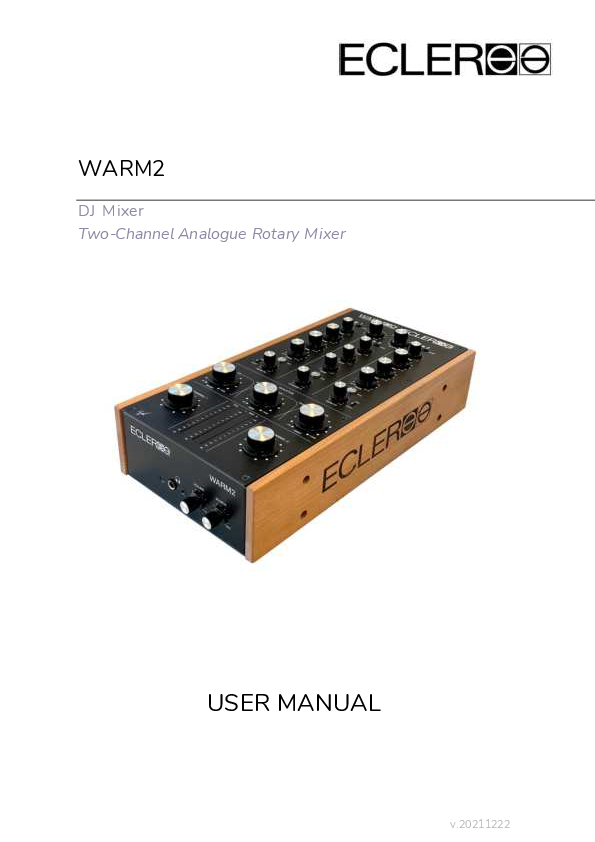
DJ Mixer Two-Channel Analogue Rotary Mixer
8 5. INTRODUCTION WARM2 is a professional two channels analogue rotary DJ mixer, designed and manufactured by ECLER in Barcelona.
PDF DJ Mixer Two-Channel Analogue Rotary Mixer
Extracted Text
WARM2
DJ Mixer Two-Channel Analogue Rotary Mixer
USER MANUAL
v.20211222

INDEX
1. IMPORTANT REMARK ............................................................................................................. 4 2. IMPORTANT SAFETY INSTRUCTIONS ............................................................................... 4 3. IMPORTANT NOTE ................................................................................................................... 6 4. WARM2 and ECLER HISTORY .............................................................................................. 6 5. INTRODUCTION ........................................................................................................................ 8
Key Features ....................................................................................................... 8 6. FUNCTION DIAGRAM.............................................................................................................. 9 7. INSTALLATION AND CONNECTION .................................................................................10
Audio Input Connections ...................................................................................... 10 Phono Inputs .................................................................................................... 11 Line Inputs ........................................................................................................ 11 Microphone Input.............................................................................................. 11
Audio Output Connections ................................................................................... 11 HOUSE Output ................................................................................................. 12 BOOTH Output ................................................................................................. 12 Record output ................................................................................................... 12 FX Send/ Return effects loop ............................................................................. 12 Headphones...................................................................................................... 12
8. QUICK START ..........................................................................................................................13 9. OPERATION AND USAGE ....................................................................................................15
Start-up ............................................................................................................... 15 Control Description .............................................................................................. 15
Input selector .................................................................................................... 15 Channel TRIM ................................................................................................... 15 Equalization ...................................................................................................... 15 M onitoring System ........................................................................................... 16 Sending to external effects units FX Send/Return ............................................. 16 Potentiometers ................................................................................................. 16 HOUSE and BOOTH output levels..................................................................... 16 10. FURTHER CONSIDERATIONS .............................................................................................17 Ground loops ....................................................................................................... 17 Background noise................................................................................................. 17 Audio connections................................................................................................ 18 Cleaning............................................................................................................... 18 11. CONFIGURATION DIAGRAM...............................................................................................19
2

12. BLOCKS DIAGRAM.................................................................................................................20 13. TECHNICAL FEATURES ........................................................................................................21 14. ECLER SIGNATURE ................................................................................................................23
3

1. IMPORTANT REMARK
The lightning flash with arrowhead symbol, within an equilateral triangle, is intended to alert the user to the presence of uninsulated " dangerous voltage" within the product's enclosure that may be of sufficient magnitude to constitute a risk of electric shock to persons. The exclamation point within an equilateral triangle is intended to alert the user to the presence of important operating and maintenance (servicing) instructions in the literature accompanying the appliance.
WARNING (If applicable): The terminals marked with symbol of " "
may be of sufficient magnitude to constitute a risk of electric shock. The external wiring connected to the terminals requires installation by an instructed person or the use of ready-made leads or cords.
WARNING: To prevent fire or shock hazard, do not expose this equipment to rain or
moisture.
WARNING: An apparatus with Class I construction shall be connected to a mains
socket-outlet with a protective earthing connection.
2. IMPORTANT SAFETY INSTRUCTIONS
1. Read these instructions. 2. Keep these instructions. 3. Heed all warnings. 4. Follow all instructions. 5. Do not use this apparatus near water. 6. Clean only with dry cloth. 7. Do not block any ventilation openings. Install in accordance with the
manufacturer's instructions. 8. Do not install near any heat sources such as radiators, heat registers, stoves,
or other apparatus (including amplifiers) that produce heat. 4

9. Do not defeat the safety purpose of the polarized or grounding type plug. A polarized plug has two blades with one wider than the other. A grounding type plug has two blades and a third grounding prong. The wide blade or the third prong are provided for your safety. If the provided plug does not fit into your outlet, consult an electrician for replacement of the obsolete outlet.
10. Protect the power cord from being walked on or pinched particularly at the plugs, convenience receptacles, and at the point where they exit from the apparatus.
11. Only use attachments/accessories specified by the manufacturer. 12. Unplug the apparatus during lightening sorts or when unused for long periods
of time. 13. Refer all servicing to qualified personnel. Servicing is required when the
apparatus has been damaged in any way, such as power supply cord or plug is damaged, liquid has been spilled or objects have fallen into the apparatus, the apparatus has been exposed to rain or moisture, does not operate normally, or has been dropped. 14. Disconnecting from mains: Switching off the POWER switch all the functions and light indicators of the amplifier will be stopped, but fully disconnecting the device from mains is done unplugging the power cord from the mains input socket. For this reason, it always shall remain readily operable. 15. Equipment is connected to a socket-outlet with earthing connection by means of a power cord. 16. The marking information is located at the bottom of apparatus. 17. The apparatus shall not be exposed to dripping or splashing and that no objects filled with liquids, such as vases, shall be placed on apparatus.
WARNING: This product must not be discarded, under any circumstance,
as unsorted urban waste. Take to the nearest electrical and electronic waste treatment centre. NEEC AUDIO BARCELONA, S.L. accepts no liability for any damage that may be caused to people, animal or objects due to failure to comply with the warnings above.
5

3. IMPORTANT NOTE
Thank you for choosing our WARM2 analogue rotary mixer!
It is VERY IMPORTANT to carefully read this manual and to fully understand its
contents before any connection in order to maximize your use and get the best performance from this equipment.
To ensure optimal operation of this device, we strongly recommend that its maintenance be carried out by our authorized Technical Services.
The Ecler WARM2 analogue rotary mixer come with a 3-year warranty.
4. WARM2 and ECLER HISTORY
Although the origins of the company date from 1965, ECLER presented its first mixer back in the 70s: the A4, a simple 4 channel mixer oriented to Super 8 film sound edition. The company grew in the 70s with the boom of disco and tourism.
It was the era of the AM 4 and AC 4, the first mixers tailored to DJ s. The AC 4 was a high fidelity mixer designed to meet the most demanding sound requirements in discos, theatres, cinemas, recording studios, conference rooms... The electronic circuits and the extreme selection of all components and transistors used, made the AC 4 a professional high quality mixer.
Milestones as SCLAT modular mixers, MAC Series High Standard Club mixers, AC-6 High-End Installation mixer (recognize as a legendary mixer by Hispasonic), the HAK Series battle mixers Designed and manufactured with expert consultation from DMC and ITF champions all over the world, or the award-winning Eternal contactless magnetic crossfader are Ecler constant innovation examples.
Ecler DJ Division Pro Team selected artists with a diverse and deep music background to share its inputs looking for the perfect mixing devices. From minimal to deep house, from techno to hip hop, from breaks to electro... all of them share our passion for music and technology. Dj's like Michael Mayer, Pastaboys, Luciano, Antoine Clamaran, Funk D'Void, Dj Hell, Ricardo Villalobos, Savas Pascalidis (to name a few). When it comes to gear, they need the maximum quality, reliability and tools to express their creativity.
Ecler mixers was installed in prestigious clubs worldwide, such as Pacha (Marrakech) or Caf� del Mar (Ibiza).
After 13 years hiatus, Ecler release a new top notch mixer:
WARM2 Warehouse analogue rotary mixer!
6

WARM2 was inspired by The Warehouse in Chicago, a place where many consider the cradle of House Music back in 1977. This place ignited the spark that eventually became the House Music scene we love and admire today. Back in the days, Frankie Knuckles, the godfather of House Music and The Warehouse first musical director, was reconstructing the soul and disco existing songs, by changing the tempo and layering different bits of percussion over them. These alterations transformed the dancefloor forever. Rotary mixers have an special feel, creating a smoother and subtler transitions. Legendary Djs like J oe Clausell, Louie Vega and more recently Floating Points or Motorcity Drum Ensemble are top class users of these particular devices. With WARM2, you'll be able to get Ecler's design expertise at your fingertips, its unquestionable audio quality, and the " Alps Blue Velvet" potentiometers precision for the perfect mix. The 4th order inbuilt isolator, will definitely expand your performance possibilities by removing frequencies, infusing drama in an acapella track, enhancing musical riffs or creating a tremolo effect by rapidly twisting the knobs. With a width of 18.5 centimetres, WARM2 is the narrowest rotary mixer on the market. Despite this, it includes interesting features such as: 3-band EQ + Trim, FX Send control and Pre/Post fader selector, and an excellent dynamic and headroom range. WARM2 provides the best analogue sound for your dancefloor in a portable format.
7

5. INTRODUCTION
WARM2 is a professional two channels analogue rotary DJ mixer, designed and manufactured by ECLER in Barcelona. With over 50 years of experience in professional analogue audio design and using the best components available on the market, Ecler offers a new rotary mixer with a new best in class warm and crystal clear analogue sound, its classic sharp filters, a 4th order isolator and its narrow portable format. All circuits are strictly designed, mounted and tested at Ecler facilities in Barcelona, in order to offer the best professional grade quality and reliability.
Key Features
� 2+1 Mixing channels � 1 MICRO input � 2 PHONO inputs � 3 LINE inputs � Master Output (HOUSE) on XLR and RCA connectors � Booth Output on RCA connectors � 6.3mm J ack and 3.5mm mini-jack Headphone Monitor Outputs � 3 band full cut EQ for main channels and 2 band full cut EQ for
MICRO/LINE channel � 3 bands isolator (300Hz and 4KHz, - /+12dB, 4th order 24dB/oct ) � Maximum Output without distortion: 21dBV (23dBu) � Mechanized from a solid block of aluminum knob, without visible screw.
Ecler Unique design � Alps Blue Velvet Potentiometers � FX Send control and Pre/Post fader selector � Screen-printed faceplate by selective anodizing � Wooden side panels included
8

6. FUNCTION DIAGRAM
1. LED indicator ON 2. Input Selector (PHONO, LINE MIC) 3. Input sensitivity adjust, TRIM 4. Treble control, HIGH 5. Midrange control, MID 6. Bass control, BASS 7. Pre-Fader listening control, PFL 8. Send switch to effect bus, PRE/POST 9. Effect Send controller, FX SEND 10. Channel volume control 11. LED VU Meter 12. Isolator control 13. Channel 3 volume control 14. Master volume control, HOUSE 15. Monitoring volume control, BOOTH 16. Stereo J ack Headphones 17. Monitor Headphones Volume control 18. PFL/MIX monitoring control, SOURCE 19. RCA Monitoring Unbalanced Output, BOOTH 20. XLR Master Balanced Output, HOUSE 21. RCA Master Unbalanced Output, HOUSE 22. External FX return Input, FX RETURN 23. External FX send Output, FX SEND 24. Recording Output, REC 25. Line Input, LINE 2 26. Phono Input, PHONO 2 27. Line Input, LINE 3 28. Phono Ground Pin 29. Microphone Input, MICRO 30. Line Input, LINE 1 31. Phono Input, PHONO 1 32. Mains Socket 33. Power Switch
9

7. INSTALLATION AND CONNECTION
Warm2 is conceived as a portable desktop mixer with a small form factor and optimized to be placed between two turntables or two digital players.
We recommend to place it in a comfortable position for the end user, without placing it in direct contact with the turntables to avoid transmitting shocks and vibrations to the styluses during use.
Because of the high gain of the PHONO and MICRO inputs, always try to place the mixer as far away as possible from noise sources (dimmers, engines, etc.) and mains wires.
The WARM2 operates with a universal input power supply and can perfectly works without any internal modification from 90V to 264V � 47 to 63Hz. Ensure that the mains-wire is far away from the signal-cables in order to avoid any possible audio hum.
In order to protect the unit from an eventual electrical overload it carries a T 0.5A fuse. Should it ever blow up, unplug the unit from mains and replace it with an identical one. If the new fuse blows again contact immediately with our authorized technical service.
ATTENTION: NEVER SHORT-CIRCUIT THE SECURITY PATH NOR USE A HIGHER VALUE FUSE.
CAUTION: Fuse substitutions have to be performed by a qualified technician.

Audio Input Connections

INPUT 1 INPUT 1

PHONO LINE

Turntable CD or Digital Deck

INPUT 2 PHONO

Turntable

INPUT 2 LINE

CD or Digital Deck

INPUT 3 MICRO

M icrophone

INPUT 3 LINE

CD or Digital Deck

10

Phono Inputs
Phono Turntables must be fitted with a magnetic cartridge with nominal output level between -55dBV and -25dBV (1.77 to 56mVrms). The WARM2 PHONO inputs (26 and 31) have high headroom (margin before saturation) and they can handle higher output cartridges than what is usual. These inputs are supplied with a nominal input sensitivity of -40dBV (10mVrms). Act on TRIM control in order to adjust the input sensitivity depending by the cartridges in use.

Line Inputs
The sensitivity of the inputs marked as LINE (27-27-30) is 0dBV (1Vrms). You can connect sound sources such as CD or digital players, as well as keyboards and other instruments.

Microphone Input

The MIC input (29) is ready for a nominal input level of -50dBV (3.16 mVrms). The connection of balanced signals is as follows:

Hot or direct signal

>

Tip

Cold or inverted signal

>

Ring

Ground

>

Sleeve

Low impedance (200 to 600) monophonic microphones must be used. For non
balanced microphones we recommend monophonic jack plugs although stereo ones are also suitable if the ring is short-circuited to the sleeve. The WARM2 includes 18V Phantom power for condenser microphones. An internal jumper allows disabling the phantom power. The WARM2 MICRO input is delivered with enabled phantom power by default (see the configuration diagram).

Audio Output Connections

HOUSE

Main power amplifier

BOOTH REC FX Send/Return Monitor

Booth/Room2 power amplifier Recording External effect devices (Input and Output) Headphones
11

HOUSE Output This stereo output feeds the PA system through balanced XLR3 connectors (20) and an unbalanced RCA connector (21). The nominal level of HOUSE output is set to 0dBV (1Vrms) by default, but it can be set to +12dBV (4Vrms) using an internal dip-switch (look at Configuration Diagram). The HOUSE output level is controlled by the HOUSE potentiometer (14).
BOOTH Output Commonly used as an independent local "Booth" output for the DJ . This stereo BOOTH (19) has unbalanced RCA connections and its level is set at 0dBV (1Vrms) but can be changed to +12dBV (4Vrms) through internal dip-switch (look at Configuration Diagram). The BOOTH level is controlled by the BOOTH (15) potentiometer.
Record output This output pair uses RCA type connectors. REC (24) is placed on the rear connection panel. The nominal level of the REC output is 0dBV (1Vrms). This output is taken post-fader, before the MASTER signal.
FX Send/Return effects loop The RCA connectors on the FX SEND output (23) and the FX RETURN input (22) allow creating a signal loop for external effects processors, samplers or sequencers. The nominal level for the SEND output, as well as for the RETURN input, is 0dBV (1Vrms). The signal sent to the FX SEND output can be taken before or behind the fader using the PRE/POST switch (8) and the send level can be set using the related potentiometer (9).
Headphones In order to obtain the best performances, Headphones should be high impedance type (200-600). Plug them in the MONITOR output (16) on the front panel: 1/4" and 1/8" stereo jack are available for connection. Sleeve is Ground, Ring is Right Channel and Tip is Left Channel.
12

8. QUICK START
Install and connect the WARM2 mixer as described in the previous chapter.
This " Quick Start" guide explains a simple procedure to route and headphone monitoring a turntable.
1. Set the controllers to their initial position Set Channel 1 TRIM, HIGH, MID and BASS (3, 4, 5 and 6) rotary controls to their central position. Set the channel potentiometer (10) to zero rotating it counter clockwise.
2. Connect your turntable Connect your turntable to the PHONO input on channel 1 (31), choose your favourite record and start to play it.
3. Connect the headphones Connect your headphones to the related output (16). Set the headphones VOLUME controller (17) to minimum level and move the SOURCE selector (18) to PFL position.
4. Connect the main power cable Connect the power cable to the power supply input (32) and turn it on using the MAINS INPUT switch (33). Both elements are located on the mixer backside.
5. Select the input source Make sure that the channel 1 input switch (2) is placed in PHONO position and press the PFL button (7). The PFL VU-meter (11) should start to work. If this doesn't happen, verify that the turntable is correctly connected and that the record is playing.
6. Adjust the input level
13

Move the TRIM (3) control until the VU-meter shows 0dB. 7. Send the signal to the HOUSE
Rotate the channel 1 potentiometer (10) clockwise at its maximum. 8. Monitor the output with your headphones
Adjust the VOLUME controller (17) to obtain a comfortable monitoring volume. Now you should hear music with your headphones. Turn the SOURCE controller (18) clockwise to crossfade from the PFL signal to the MIX signal. When this controller is completely turned to the right, only the MIX signal will be monitored. In this case the PFL and the MIX signal are both referred to channel 1 so you will listen the same signal in both positions. 9. Check the EQ operation Adjust the EQ of the track with the 3-way stereo equaliser (4, 5, 6) and unleash your creativity with the powerful 3-way isolator (12). This 4th order tone control has been designed for a creative sound edition: each way can be individually isolated and boosted using the big and ergonomic rotary controllers.
14

9. OPERATION AND USAGE
Start-up
Switch on the mixer using the switch (33) located in the mixer back panel. Now the LED ON (1) indicator will be lit in green. Even if the typical bump noise of audio devices during the start-up is minimized in the WARM2 thanks to the internal antibump circuits, it is always recommendable to turn on the devices using the following sequence:
1. Sound sources 2. Mixer, sound processors, effects 3. Finally, power amplifiers
The shut-down routine should be done by following the exact reverse sequence in order to avoid any possible damage to the loudspeakers.
Control Description
Input selector Each channel provides an input toggle switch selector (1) that allows selecting the PHONO or LINE inputs for the main channels and MIC or LINE inputs for the third channel.
Channel TRIM All the WARM2 input channels have an accessible TRIM input sensitivity control (3). These controls adjust the input level of each channel in order to compensate the level of different sources connected to the mixer, or different phono cartridges in case of turntables. The gain adjustments should be done with great care, using as a reference the PFL VU-meter (11). The standard level reference used to mix audio signals is 0dBV.
Equalization The rotary tone controls for each channel provide a +10/-30dB boost/cut at high (4) and low frequencies (6) and +10/-25dB at the mid range (5). This control allows equalizing the track in use or it can be used in all the creative ways possible. In
15

addition to the channel EQ, a powerful 3-way Isolator (12) is available on the main output. It provides a +12/-70dB boost/cut at high and low frequencies and +12/ -40 dB at the mid range. This great attenuation range is specially designed for creative live performance.
ATTENTION: Use equalization carefully; by boosting too much the low frequency range, you can induce an excessive displacement of the loudspeakers membrane.
Monitoring System
WARM2 is equipped with a flexible and easy monitoring system that will allow the performers to finely tune PFL (Pre-fader listening) and Mix levels of each input through the VU-METER and the HEADPHONES. Each channel can be monitored visually and pre-listened pressing the dedicated PFL (7) button.
For HEADPHONES monitoring, the SOURCE rotary potentiometer (18) allows you to blend a selected PFL together with the main MIX Program. The VOLUME rotary potentiometer (17) controls the level of headphones output.
Sending to external effects units FX Send/Return
The 2 main channels of WARM2 are equipped with rotating potentiometers (9) that allow sending the signal to an external effects unit, sampler, etc. These potentiometers allow to precisely adjusting the signal level sent from each channel.
The FX SEND output (23) has to be connected to the effects processor's input and its output to the RETURN input (28) or any LINE input (35).
This signal send can be configured either PRE or POST fader with the PRE/POST toggle switch (10).
Potentiometers
The WARM2 is equipped with original J apanese ALPS blue velvet potentiometers that offer extremely soft and smooth transitions both for channels and isolator controls.
HOUSE and BOOTH output levels
WARM2 features two main output level controls: HOUSE and BOOTH. The master level is controlled by the HOUSE (14) level knob. The BOOTH level is controlled by the BOOTH (15) level knob.
IMPORTANT: With the default output settings of 0dBV (look at Configuration Diagram) and when the HOUSE (14) or BOOTH (15) potentiometers are at their maximum position, the output signal levels of HOUSE (20-21) and BOOTH (19) will
16

faithfully follow the MIX VU-meter (11) indications, in order to have a real perception of the signal output. As the MIX VU-Meter is monitoring the MIX bus and not the outputs, when the internal extra-gain of 12dBV is set on the outputs (look at Configuration Diagram) and when the HOUSE or BOOTH potentiometers are at their maximum position, the VUMeter indications will be displaced of +12dBV: 0dBV corresponds to +12dBV. HOUSE output (20) is electronically balanced so the unbalanced level (21) always matches with the balanced level (20). WARM2 has extended headroom: its maximum output without distortion can reach 21dBV (23dBu)! Take care of the devices connected to the mixer outputs checking the VU-meters and please try to stay away from the red light zone!
10. FURTHER CONSIDERATIONS
Ground loops
Avoid that the sources connected to the mixer and the devices connected to its output have their ground reference interconnected; it means that the ground reference should never have two or more different paths, because hums and noise can appear influencing the sound quality. In order to avoid ground loops, ensure that the shielding of cables, if connected to the chassis, are never connected with each other.
Background noise
The use of active circuitry can yield, depending on the configuration, to a significant noise level. The WARM2 have been specifically designed with a very reduced noise figure. Anyway, the noise level will always depend by the correct use and installation of the mixer and by the correct gain chain. It is not the same setting up the channel potentiometer at "2" and the HOUSE level at "10" that vice versa. In the first case you get a poor signal to noise ratio that will be fully amplified by the master output while on the second we have a good signal to noise ratio only amplified by "2". As a result, the background noise is greater in the first case than in the second one.
17

Audio connections As a general rule of thumb, make the signal connections as short as possible and use the best connectors and cable available. Cables and connectors are frequently held cheap, forgetting that a bad connection can result in a poor sound quality. Cleaning The control panel should never be cleaned with solvent or abrasive substances as it could become damaged. To clean it, use a slightly moist soft cloth, together with a neutral liquid detergent, and then dry it with a clean cloth. We suggested removing all sweat stains after use. Be careful to ensure that liquids never enter in the machine through any of the openings.
18

11. CONFIGURATION DIAGRAM
19

12. BLOCKS DIAGRAM
20

13. TECHNICAL FEATURES

WARM2 Audio Performances

Inputs Sensitivity nom / Im pedance
Outputs Level/Minimum Load
Frequency Response
THD+N
CM M R Signal Noise Ratio
Max Undistorted Output Level Trim control
Tone control Inputs 1-2 Tone control Input 3 Tone control Isolator
Tone Filter cut frequency at -6dB (slope 12dB/oct)
Isolator cut frequency at -6dB (slope 24dB/oct)

LINE PHONO M ICRO FX RETURN
HOUSE (BAL) HOUSE (UNBAL) BOOTH (UNBAL) REC HEADPHONES FX SEND
LINE M ICRO PHONO FX RETURN
LINE M ICRO PHONO FX RETURN
M ICRO
LINE M ICRO PHONO FX RETURN
HOUSE (Electr.BAL) HOUSE (UNBAL) BOOTH (UNBAL)
INPUTS 1-2 INPUT 3
BASS MID TREBLE
BASS TREBLE
BASS MID TREBLE BASS MID TREBLE
BASS MID TREBLE

0dBV/ 50k -40dBV/ 50k -50dBV/ >1k
0dBV/ > 6k
0dBV/600 1V *(+12dB 4V) 0dBV/2.2k 1V *(+12dB 4V) 0dBV/2.2k 1V *(+12dB 4V)
0dBV/ 10k 200m/200 THD 1%
0dBV/ 2. 2k
10Hz�30kHz -1dB 10Hz�25kHz -1dB
RIAA �0.5dB 10Hz�50kHz -1dB
<0.006% <0.9%
<0.08% <0.005%
>70dB @ 1kHz
>99dB >85dB >98dB >100dB
21dBV (23dBu) 21dBV (23dBu) 21dBV (23dBu)
� 15dB � 20dB
+ 10/ -30dB + 10/ -25dB + 10/ -30dB
� 15dB � 15dB
+ 12/ -70dB + 12/ -40dB + 12/ -70dB
200Hz 200Hz�6.8kHz
6.8kHz
300Hz 300Hz�4kHz
4kHz

21

Inputs

Outputs

Connectors

LINE 1-2-3 PHNONO 1-2 MICRO 3 FX RETURN

RCA STEREO RCA STEREO 6.3mm TRS BAL. J ACK RCA STEREO

Miscellaneous

Connectors

HOUSE (BAL) HOUSE (UNBAL) BOOTH FX SEND REC HEADPHONES

XLR STEREO RCA STEREO RCA STEREO RCA STEREO RCA STEREO 6.3mm/3.5mm STEREO J ACK

Control Mode Rotary with Alps Blue Velvet Potentiometers
Phantom Voltage 18VDC/5mA Max (Default ON)
MIX and PFL VU-Meter LED 12 segments (-30dBV � +20dBV) Operation

Operation Temperature -5�C - 45�C / 23�F - 113�F

Supply

Humidity 20 - 90% RH (no condensation)

Mains voltage 90-264VAC 47-63Hz
Rated power consumption 30VA Mechanical

Dimensions (without wooden 400 x 185 x 100mm / 15.7" x 7.2" x 3.9" sides)
Weight 3.6Kg / 7.94 lbs

22

14. ECLER SIGNATURE
WARM2 shows the classic Niiffics signature on the front plate. This is the historical signature of the R&D teams at Ecler during the years.
23