BLtouch Creality For Creality V1 安装说明书 20181110v11
File info: application/pdf · 2 pages · 1.96MB
BLtouch Creality For Creality V1 安装说明书 20181110v11
BLtouch Creality For Creality V120181110v11
Circuit Wiring Platform Adjustment Install BLTouch Software Setti
E-mail: info@creality3d.cn cs@creality3d.cn. SHENZHEN CREALITY 3D TECHNOLOGY CO., LTD. AUTO BED LEVELING SENSOR FOR 3D PRINTER. BLTouch Guidebook.
Visit
Creality Bltouch Firmware Update Database › Url: Images-na.ssl-images-amazon.com
Full PDF Document

If the inline viewer fails, it will open the original document in compatibility mode automatically. You can also open the file directly.
Extracted Text
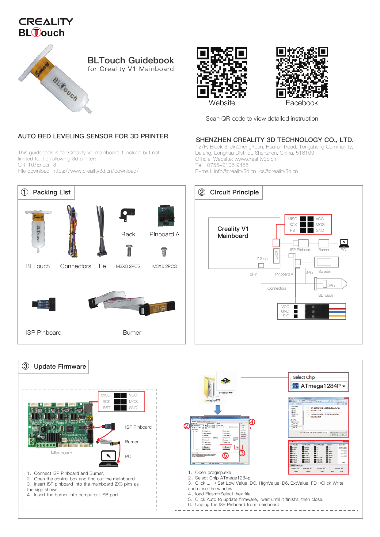
BLTouch Guidebook
for Creality V1 Mainboard

AUTO BED LEVELING SENSOR FOR 3D PRINTER
This guidebook is for Creality V1 mainboard.It include but not limited to the following 3d printer: CR-10/Ender-3 File download: https://www.creality3d.cn/download/
 Packing List

Website

Facebook

Scan QR code to view detailed instruction

SHENZHEN CREALITY 3D TECHNOLOGY CO., LTD.
12/F, Block 3, JinChengYuan, Huafan Road, Tongsheng Community, Dalang, Longhua District, Shenzhen, China, 518109 Official Website: www.creality3d.cn Tel: 0755-2105 9455 E-mail: info@creality3d.cn cs@creality3d.cn

 Circuit Principle

Rack Pinboard A BLTouch Connectors Tie M3X8 2PCS M3X6 2PCS

ISP Pinboard

Burner

Creality V1 Mainboard

MISO SCK RST

VCC MOSI GND

Z Stop

EXP1

ISP Pinboard Burner

PC

2Pin

Pinboard A

Connectors

VCC GND SIG

3Pin Screen 5Pin
BLTouch

 Update Firmware

MISO SCK RST

VCC MOSI GND

Mianboard

ISP Pinboard Burner PC

1Connect ISP Pinboard and Burner. 2Open the control box and find out the mainboard 3Insert ISP pinboard into the mainboard 2X3 pins as the sign shows. 4Insert the burner into computer USB port.

ATmega1284P

1
2

4

53
1Open progisp.exe 2Select Chip ATmega1284p. 3Click ...  Set Low Value=DC, HighValue=D6, ExtValue=FDClick Write and close the window. 4load FlashSelect .hex file. 5Click Auto to update firmwarewait until it finishs, then close. 6Unplug the ISP Pinboard from mainboard.

 Install BLTouch

 Circuit Wiring

1Insert connectors into 5 Pin Port.

2Install BLTocuh on the rack with 2 M3X6 screws

3Loosen all fan cover screws, Install the farme on the corresponding position with 2 M3X8 screws

4Secure the cable to the guide tube and cable with a cable tie and bypass the rear side of the gantry.

 Platform Adjustment

12

Screen

1Unplug the screen cable, connect

3

4

the pinboard A to the screen port (EXP1).

2Insert the screen cable into 10

pins port.

3insert the connectors to the 3

pins port as the sign shows.

4Unplug the Z limit switch(Z-stop

port),and insert the connectors.

1PrepareAuto homeand wait until it stops.

figure 3

0.2mm A4 paper

"

2PrepareMove axisMove ZMove 0.1mmRotate the knob until the distance between them is about 0.2mmas a sheet of A4 paperwrite down the value of A.
3Rotate the knob until the distance between them is about 0.2mmas a sheet of A4 paperwrite down the value of AFor example, figure 3 .

#

$

4ControlMotionZ Offsetwrite down the value of Bthen rotate the knob until it comes out as: C=B+A. Return Control and Select Store settings.

 Software Settings

pen Cura

Settings Printer-anage Printers

Machine Settings

Change "G28" to "G28 X0 Y0 G29 Z0"