Important Safety Information & Guidelines
WARNING: Read the entire instruction manual before you start installation and assembly. If you have any questions regarding any of the instructions or warnings, please contact your local distributor for assistance.
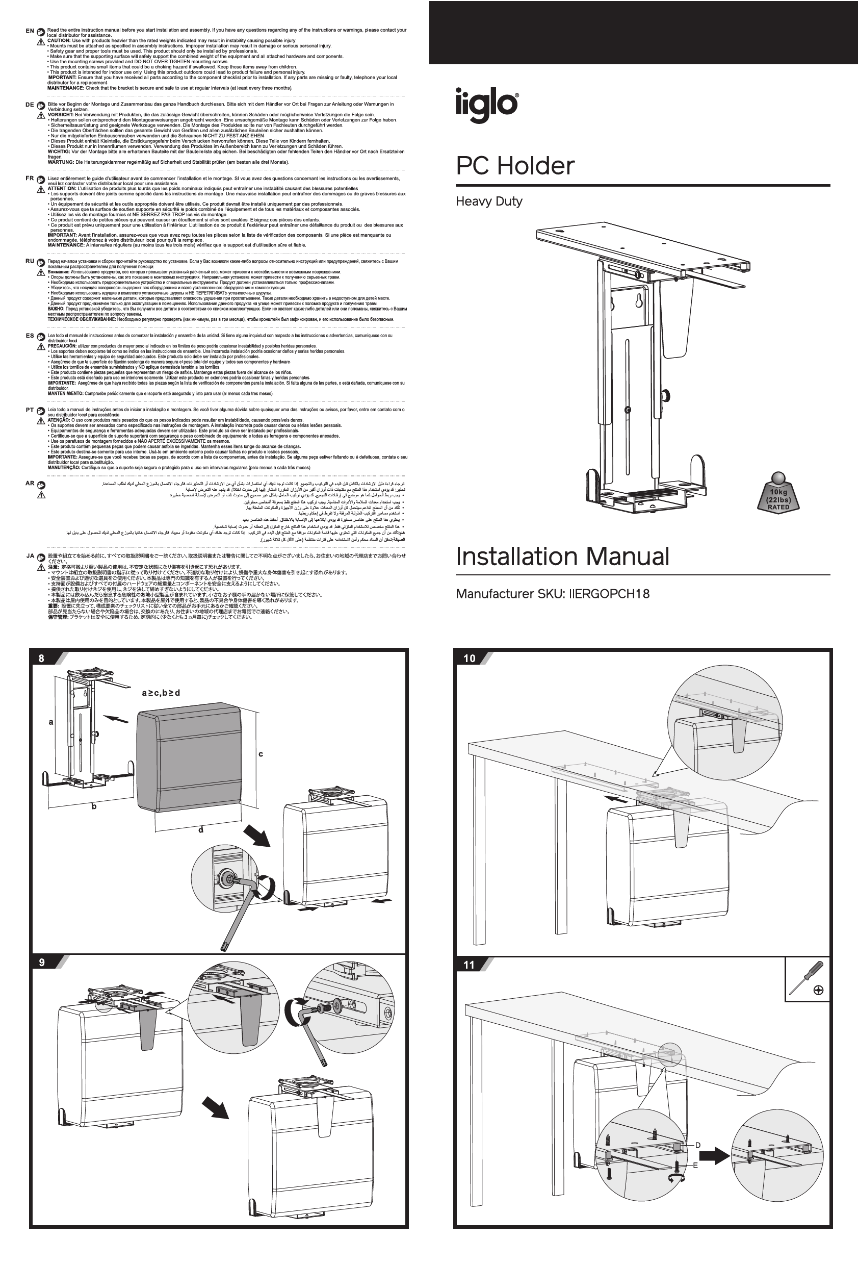
CAUTION: Use with products heavier than the rated weights indicated may result in instability causing possible injury, damage or serious personal injury.
- Mounts must be attached as specified in assembly instructions. Improper installation may result in damage or serious personal injury.
- Safety gear and proper tools must be used. This product should only be installed by professionals.
- Make sure that the supporting surface will safely support the combined weight of the equipment and all attached hardware and components.
- Use the mounting screws provided and DO NOT OVER TIGHTEN mounting screws.
- This product contains small items that could be a choking hazard if swallowed. Keep these items away from children.
- This product is intended for indoor use only. Using this product outdoors could lead to product failure and personal injury.
IMPORTANT: Ensure that you have received all parts according to the component checklist prior to installation. If any parts are missing or faulty, telephone your local distributor for a replacement.
MAINTENANCE: Check that the bracket is secure and safe to use at regular intervals (at least every three months). ⚙️
Parts List
| Identifier | Description | Quantity |
|---|---|---|
| A | Main Bracket Assembly | x1 |
| B | PC Holder Tray | x1 |
| C | Support Arm | x1 |
| D | M6x12 Screws | x4 |
| E | M6x16 Screws | x4 |
| F | Wood Screws (for desk mounting) | x6 |
| G | M4x10 Screws | x2 |
| H | M4 Nuts | x2 |
| I | M4 Washers | x2 |
| J | Cable Management Clips | x12 |
| K | 4mm Allen Key | x1 |
| L | 5mm Allen Key | x1 |
Assembly Instructions
Follow these steps carefully for proper installation.
-
Step 1: Prepare Main Bracket Assembly
Attach the support arm (C) to the main bracket assembly (A) using two M6x12 screws (D) and the 4mm Allen key (K). Then, attach the PC holder tray (B) to the main bracket assembly (A) using two M6x16 screws (E) and the 5mm Allen key (L). Ensure parts are aligned correctly.
Diagram Description: Shows parts A, B, C, D, E, K, L. Illustrates attaching C to A with D and K, then B to A with E and L.
-
Step 2: Desk Mounting Preparation
Determine the desired mounting location on the underside of your desk. Use the provided wood screws (F) to secure the main bracket assembly (A) to the desk. A measurement of approximately 16mm from the desk edge is indicated for optimal placement. Ensure the supporting surface is stable and can bear the weight.
Diagram Description: Shows the main bracket assembly (A) being positioned under a desk. Illustrates using wood screws (F) for attachment, with a measurement of 16mm from the desk edge and a 3mm gap indication.
-
Step 3: Secure Support Arm
Ensure the support arm (C) is correctly positioned and securely attached to the main bracket assembly (A) using the remaining two M6x12 screws (D) and the 4mm Allen key (K).
Diagram Description: Close-up view showing the attachment of the support arm (C) to the main bracket assembly (A) with screws (D) and Allen key (K).
-
Step 4: Attach PC Holder Tray
Attach the PC holder tray (B) to the main bracket assembly (A) using the remaining two M6x16 screws (E) and the 5mm Allen key (L). Verify that the tray is level and securely fastened.
Diagram Description: Shows the PC holder tray (B) being attached to the main bracket assembly (A) with screws (E) and Allen key (L).
-
Step 5: Install Cable Management Clips
Affix the 12 cable management clips (J) to the designated areas on the assembled bracket. These clips help organize and secure your PC's cables.
Diagram Description: Shows the placement of cable management clips (J) onto the assembled PC holder structure.
-
Step 6: Final Mounting Check
Double-check that all screws are tightened appropriately (but not over-tightened) and that the entire assembly is securely attached to the desk. The PC holder is now ready to have a PC placed in it.
Diagram Description: Shows the fully assembled PC holder mounted under a desk.
-
Step 7: Adjustments (if applicable)
Some models may feature adjustment mechanisms for height or angle. If your model includes parts G, H, and I, use them with the Allen key (K) to make any necessary adjustments as shown in the diagram. Typically, this involves securing a specific position.
Diagram Description: Illustrates a detail of an adjustment mechanism using screws (G), nuts (H), washers (I), and Allen key (K), possibly for setting height or tilt.
Product Overview
The iiglo Heavy Duty PC Holder (Model IIERGOPCH18) is designed to securely mount a PC tower under a desk, freeing up floor space and improving desk organization. It features a robust construction capable of supporting up to 10kg (22lbs) and includes cable management clips for a tidy setup. Installation is recommended for professionals, ensuring stability and safety.
