File info: application/pdf · 154 pages · 86.61MB
Document preview and download links are below.
Extracted Text
electronics.
A M cGr aw-H ill W eekly
75 Cents
April 12, 1963
DElJTERIUM TIIYRATRON
New pulse modulator handles 150 Kw, p 94
(photo below)
SEISMIC-WA VE COMMUNICATIONS
Latest medium: the earth itself, p 51
ARMY AIR FORCE REBORN
Non-nuclear fore es plan inventory, p S.'B
..H'1V:} SO.!'!'! 01
h.l . G1:! fJO.!.DIJIAO~ OZO1
B3fmI}1S �<I ll
Ne.W STANDARD
Sweep- Frequency Generator
Sweep Generator
C W Generator
Marker Generator
Attenuator
and O utput Meter
Type 1025- A
Stand a rd
Sweep-Frequency Generator
Price : $3250 in U. $.A.
In One Instrument ... Everything you need
" � 0
Ra nges : 0.7 -1.4 Mc
1.3-2.6 Mc 2.4�4.8 Mc
4-8 Mc 7- 14 Mc 13-26 Mc 24-48 Mc
40�80 Mc 65-140 Mc 100-230 Mc
Bandspread Rang es: 400 to 500 kc and 10 .4 to 11 Mc. Other ranges available on specia l order.
Sweep Width: Enti re selected range is swept. However, visual presentation of swept range can be expanded to permit full oscilloscope di splay of
portions of range as small as 103 with EXPA ND DISPLAY and DI SPLAY START conlrols.
Selected range is swept from low end to high end in 22.2 msec twenty times a second . Output is blanked oH during return sweep. A saw�looth sweep voltage is provided which is synchronized
with frequency , and adjustable in starting point and amplitude (DISPLAY START and EXPAND DISPLAY controls. respectively) .
Stability : Drift less than ::e 0 .13 for frequency for 5 hours after one.hour warm.up . Frequency dial accuracy is within ::e0.53.
Marker: Continuously adjustable from 3mv to Iv ; multip lier effectively e~te11ds range to lOOv. Accuracy of indication is typically better than ::::1:: 103. Shape and width of marker permit resolu � tion to better than � 0.13 of indicat ed frequency .
RF Output: Adjustable from 0.3,uv to Iv behind SO ohms ( - 123 to 7 dbm power into SO ohms.) Output is flat to within �>13 up to 100 Mc and within ::e33 up to 230 Mc. RF amplitude indica ted to a typical accuracy of better than ::e 103.
for Quantitative Frequency Response Measurements
* Covers 0.7 to 230 Mc in ten over lapp ing
octave ranges plus two bandspread ranges (400 to 500 kc and 10.4 to 11 Mc) .
* Has th e "perfect marker" . .. continuous ly
adjustable both in frequency and amp litude ... accurately calibra ted in frequency and amp litude . . . lets you take data directly from dis pla y ... does not interfere with response display ... a sing le unambiguous marker, nqt a confusing string of pips.
* Marker permits
frequency measurements to 0.5 % direct ly from d isp lay.
* Instantly converts from sweep to cw
operation for accura te point-by-point meas uremen ts without cha ngin g adjustments or connections. Separate output
drives frequency counters directly for accurate measurements of low-level devices.
* Meter measures both rf input and detected
output of device being tested.
* Accessory high-impedance detector probe
s uppli ed with instrument s impli fies respo nse measurements - minimizes circuit loading.
"What signal generators are to oscillators this instrument is to sweep generators"
* Accurate frequency ca libration �0.5% of readin g.
* Stabl e . .. no annoying drift of displayed respon se. Low residual Im permits investigations of steep response slopes.
* Motor-driven capacitor produces a high-level swept signal free from harmonic distortion a nd spurious outputs.
* No awkward interactions between contro l s. * Low l eakage permits measurements to 0.3 �v. *Accura te. 120-db attenua tor ha s low l.01 VSWR .
G ENERAL RA DIO COMPA N Y
WEST CONC ORD , MASSACHUSETTS
NEW YORK, N. Y., 964-2711
CHICAGO
PHILADELPHIA, 424-7419 WASHINGTON , O.C. SYRACUSE
Rideefield. N. I.. 943 -3 140 (Oa k Park) 848�9400
AbinRton. 887�8486
(Rockville, Md .) 946-1600 454�9323
DALLAS fl 7-4031
SAN FRANCISCO LOS ANGELES ORLANDO, FLA.
( Los Altos) 948�8233
469�620 1
425�4671
CIRCLE 900 ON READER SERVICE CARD
In EUROPE General Radio
Overseas
Zurich, Switzerland
IN CANADA
(Toronto) 247-2171
W. W. MacDONALD, Editor
J. M . CARROLL, Managing Editor
SENIOR EDITORS Samuel Weber, George W. Sideris
SENIOR ASSOCIATE EDITORS Michael F. Wolff, John F. Mason
ASSOCIATE ED ITORS Michael F. Tomaino, Sylvester P. Carter, William P. O'Brien, Sy Voge l, Leslie Solomon, George J. Flynn, Laurence D. Sherga l is, George V. Novotny, Leon H. Dulberger
ASSISTANT EDITORS Nilo Lindgren, Stanley Froud, Stephen B. Gray, Roy J. Bruun, Barry A . Briskman
REGIONAL EDITORS Harold C. Hood (Pacific Coast, Los Angeles), Thomas Maguire (New England, Boston), Cletus M. Wiley (Midwest, Chicago)
ART DIRECTOR Howard R. Berry
ASSISTANT ART DIRECTOR John C. Wright, Jr
EDITORIAL ASSISTANTS Lorraine Rossi , Virginia T. Bastion, Lynn Emery, Ann Mello , Lorraine Werner, Alice M . O'Brien, Sharon Porks, Patricio Mitchell, Claire Benell
FOREIGN NEWS BUREAU DIRECTOR, John Wilhelm;
Alyne Elias, Charles Oberto nce LONDON-John Shinn, Derek
Barlow, Nicholas London BONN-Bruce Bendow,
Richard Mikton, Silke McQueen BRUSSELS-Peter Forboth PARIS-Robert Farrell,
Arthur Erikson MILAN-Marc A. Messina MEXICO CITY-Wesley Perry, Jr RIO DE JANEI RO-Leslie Warren MOSCOW-Stewart Ramsey TOKYO-Richard Holloran,
Charles Cohen, John Yamag uchi
CIRCULATION MANAGER Hugh J. Quinn
W. W. GAREY, Publisher
April 12, 1968
electronics A McGraw-H ill Weekly 75 Cents
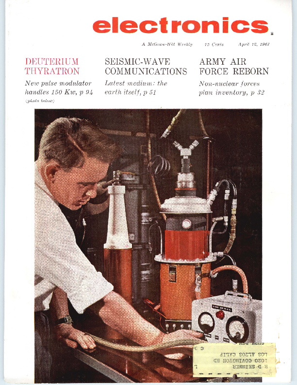
HEAVY-HYDROGEN THYRATRONS will be used in high-power
radar and accelerators where their ability to modulate such
high power is becoming increasingly important (General Elec-
tric, Ltd.). Others will fulfill space communications needs.
Se e p 94
COVER
LASER MEETINGS Double Up. Here's a preview of two im-
portant conferences next week. At New York, one report is on
ultrasonic control. In Pittsburgh, the emphasis will be on
chelates
22
ORBITING OBSERVATORY Nears Flight Tests. Stabilization and control system for the Orbiting Astronomical Observatory "flies" in vacuum chamber. Unusual facility tests star trackers 28
ARMY OF THE AIR Creates New Market. Army is buying 1,600
planes and a host of subsystems. Air-mobility and non-nuclear
capability calls for new gear
32
RESIST ANCE P AT HS Associate Terms. Experimental retrieval
system associates stored information as voltage levels. It's one
example of bionics research
39
BROAD CAST ENGINEERS Report New Systems. A-m/f-m mu l-
tiplex is among new gear reported at NAB conference. An-
other is f our-vidicon cameras for sharper color tv
42
COMMUNICATING BY SEISMIC WAVES: New Transducers and Design Details. Man has learned to communicate through air, water and space. Given the proper transducer, the earth itself can be a communications medium. Such a seismic system could also watch for earthquakes or nuclear blasts and study geological structures. By K. Ikrath and W. Schneider, U.S. Army Electronic R&D Lab. 51
UNUSUAL WAVEFORM ANALYZER Aids Automatic Testing.
This programmer-computer enables unskilled operators to make
complex electrical measurements. It uses tunnel diodes to sense
peak amplitudes, rise and fall times and pulse widths. These are
converted to voltage analog outputs for meter display or record-
ing.
By R. W. Jones, General Electric 56
CRYSTAL- CO NTROLL ED MULTIVIBRATOR Has Better Stability. Conventional astable multivibrators may be useless for generating pu lses and square waves with good stabil ity and r ise and fall times because of basic instability. Piezoelectric crystals in the cross coupling circuit can overcome this problem By H . R. Newhoff, L itton Systems 60
R ELIABILITY I N S E MICO N DUCTOR CIRCUITS : Eigh t Ways to Get It. Here are a few basic principles and their application to logic gates, buffers, power switches, flip flops, monostable multivibrators and pulse stretchers. Among other schemes, diode quadding and use of redundant transistors are important. By K. L. H a ll, R adiation Inc. 62
Contents continued
electronics
April 12, 1963 Volume 36 No . 15
Published weekly, with Electronics Buyers' Guide as part of the subscription, by McGraw-Hill Publishing Company, Inc . Founder: James H. McGraw (1860-1948).
Title � registered U.S. Patent Office ; � copyright 1963 by McGraw-Hill
Publishing Co ., Inc. All rights re served, including the right to reproduce the contents of this publication, in whole or in part.
Executive, editorial, circulation and advertising offices : McGraw-Hill Building, 330 West 42nd Street, New York 36, N. Y. Telephone Longacre 4-3000. Teletype TWX N.Y. 212-640-4646. Cable McGrawhill, N. Y. PRINTED IN AL BANY, N. Y.; second class postage paid at Albany, N . Y.
OFFICERS OF THE PUBLICATIONS DIVISION: Shelton Fisher, President; Vice Presidents : Joseph H. Allen, Operations; John R. Callaham, Editorial; Ervin E. DeGraff, Circulation; Donald C. McGraw, Jr., Advertising Sales; Angelo R. Venezian, Marketing.
OFFICERS OF THE CORPORATION : Donald C. McGraw, President; Hugh J. Kelly, Harry L. Waddell, Executive Vice Presidents; L. Keith Goodrich, Executive Vice President and Treasurer; John J, Cooke, Vice Pre sident and Secretary.
Subscriptions are solicited only from tnose actively engaged in the field of the publication . Position and company connection must be indicated on orders . Subscription rates: United States and Possessions, $6.00 one year, $9.00 two years, $12.00 three years. Canada : $10.00 one year. All other countries $20.00 one year. Single copies, United States and Possessions and Canada 75�. Single copies all other countries $1.50.
THE PUBLISHER, UPON WRITTEN REQUEST FROM ANY SUBSCRIBER TO OUR NEW YORK OFFICE AGREES TO REFUND THAT PART OF THE SUBSCRIPTION PRICE APPLYING TO COPIES NOT YET MAILED.
Subscribers: Please address change of address notices, subscription orders or complaints to Fulfillment Manager, Electronics, at above address. Change of address notices should provide old as well as new address, including postal zone number if any. If poi� sible, attach address label from recent issue. Allow one month for change to become effective.
Postmaster : Please send Form 3579
to Fulfillment Manager, Electronics,
.�. � 330 West 42nd Street, New York 36,
New York.
,, .......
:~... '�I ��~
..,...�
Audited Paid Circulation
2
CONTENTS continued
FIELD-EFFECT TRANSISTORS: Now Used in Low-Noise Preamplifier. These components are creating high interest but tried and tested applications are still few and far between. In this one, off-the-shelf units make up a circuit that combines low noise and high input impedance with gain stability with temperature changes. By E. G. Fleenor, Lockheed 67
SHRINKING PHOTOFLASH CONTROL: Solid-State Components Do It. As part of an experiment with a particle accelerator, the control signal is a light pulse from a photofiash tube. It is directed through a telescope at a receiver that is ~-million volts above ground. By E. L. Harris, Jr., Lawrence Radiation Lab 70
REFERENCE SHEET: Thin-Film-Resistor Short Cut. Interdependence of length, width, resistance and power-handling ability can require tedious calculations in thin-film resistor design. This graphical method can be a real time saver. By H. L. Cook, Martin Company 72
DEPARTMENTS
Crosstalk. The New Army
3
Comment. Servo Amplifiers. CGE, not CSF
4
Electronics Newsletter. Radiation Decay Nil in
Van Allen B elt
7
Washington This Week. Pentagon Ponders De-
preciation Allowance
12
Meetings Ahead. Design and Use of Microwave
Valves (Tub es) Symposium
44
Research and Development. Vacuum Deposited
Circuits Use F ield Effect
80
Components and Materials. New Thyratron Peaks
at 200 Mw
94
Production Techniques. Spot-Testing Aids Manu-
facture of High-Reliability Relays
106
New Products. Data Converter has 60-Db D ynamic
Range
118
Literature of the Week
132
New Books. Nonlinear Automatic Control
134
People and Plants. Melabs Moves Manufacturing
Activities
138
Index to Advertisers
150
April 12, 1963 � electronics
The New Army
CROSSTALK
THE ILLUSTRATION reproduced here isn't from science fiction. It's taken from the Army Information Digest and it represents a guesstimate of what the Army will look like in the not-too-distant future. The missiles are already on hand, the jet-propelled soldiers, weapons delivery systems and transport will come.
The groundwork for this Army of the future is being laid right now, through the plans and programs outlined this week on p 32 through 36. The Army is concentrating on modernizing its forces, making its firepower more versatile, acquiring mobility, tightening its command and control functions.
Foot-slogging won't disappear, but a significant portion of the Army will return to the air to give the Army greater ability to perform any kind of land mission-in any climate, over any terrain, from small local actions through general nuclear war and its aftermath. Aviation is an important part of this overriding aim because, the Army says, it permits substantial improvement in tactical mobility on the battlefield.
Before strategic warfare concepts shifted to missiles, massive force represented by armies was the clincher in a war. Now the Army must be prepared to unleash swift action while keeping brute force carefully in reserve.
"Tactical nuclear war and large-scale nonnuclear war will be subject to increasing restraints on both sides because of the danger of escalation into a general nuclear exchange," says Gen. Barksdale Hamlett, Army vice chief of staff. Unless the USSR achieves a technical breakthrough-like an effective ICBM defenseto upset the present condition of nuclear deterrence, Hamlett expects the cold-war pattern of small, local conflicts to continue. The Army stresses that it must be able to fight both the big wars and the small wars, but it sees the latter as more likely.
Soviet ground forces, the Army figures, is thinking along the same lines. Army expects the USSR to emphasize mobility, increasing nuclear and non-nuclear firepower, better communications, missile and rocket artillery and battlefield surveillance-in short, everything the U.S. Army believes is essential.
By 1970, the Army expects to be able to field more air-mobile and combat support units, to have new types of aircraft to move and supply troops and for reconnaissance and surveillance. Airborne target-sighting systems will feed data to ground computers that direct artillery fire.
electronics � April 12, 1963
Antitank weapons will be operated by automatic fire control and command guidance systems. Troops will be well-supplied with Pershing, Sergeant, Lance, Redeye, Mauler and other missiles. For short range communications, systems like Rada ( ELECTRONTCS, p 18, April 5) will be used, and for long range communications, satellite systems. Portable reactors will power command and communications centers, radar, depots, weapons systems and other field unitsthe prototypes are already in operation. Behind the scenes, inventory control systems, communications nets between depots and contractors and many other electronic logistical aids will be in operation.
The list of modern equipment that the Army will have in 1970 is far longer than that and will undoubtedly include systems not yet conceived.
Any electronics engineer or company that feels he can make a contribution to Army equipment will find a willing ear. But, says Gen. Earle G. Wheeler, Army chief of staff, Army is not looking for minor improvements in what it already has. It wants large-scale technical improvements that will make material contributions to the toughness and flexibility of land forces. "Gadgets and frills," says Wheeler, won't be bought.
3
f Anafab
I 00~�;1��
~..� the industry's finest dual-trace oscilfoscope
the only oscilloscope on which you can make PRECISE QUANTITATIVE
MEASUREMENTS! USE AS PRECISION AC & DC VOLTMETER,
PHASE METER, TIME-INTERVAL METER.
� Superior triggering and over-all stability
� Highest sensitivity (lOO�v/cm) � Both single-ended and
differential amplifier inputs, AC or DC-coupled � No interpolation needed with direct-reading Null�Balance dials � "Instantaneous" beam finder � Delayed trigger output from 1 �sec to 50,000,000 �sec � Bandwidth from DC to 150 kc
Call or write for specifications on the 1120/700 and on the full line of Analab scopes, scope camera systems, and accessories.
Analab Instrument Corporation
Cedar Grove, New Jersey
Ana/ab
AsubsldlaryolTHE JERROLD CORPORATION.
4 CIRCLE 4 ON READER SERVICE CARD
COMMENT
Servo Amplifiers
I was very interested in the article, Designing Servo Amplifiers For High Efficiency (p 62, Feb. 8), by J. A. Walston and J. E. Setliff of Texas Instruments, since it followed closely after my article, Versatile Servo Amplifier for 50, 60 or 400-Cycle Operation (p 44, Jan. 18) .
I think, however, that a section on the advantages and disadvantages of unfiltered d-c should have been added. Using a full-wave rectified, unfiltered, a-c sinewave for power to a push-pull servo amplifier can also generate quite a few problems.
As advantages I would list: (1) theoretically high efficiency approaching 100 percent at full output; (2) low power-supply impedance; (3) low distortion in the output sinewave especially at full output; and (4) quadrature rejection due to the fact that the power supply voltage is zero at the point of maximum quadrature signal.
As disadvantages: (1) Poor stability of power-supply voltage because of line fluctuation requires higher-voltage transistors. (2) Line spikes and transient pulses will be directly passed to the output transistors and can be extremely dangerous. (3) Input phase must be locked to power-supply voltage or line phase. An a-c servomotor's torque is reduced by only the cosine of the phase angle as it varies with respect to the motor's reference voltage. This means that phase in a standard amplifier is not too critical. Phase shift of the input voltage, however, with unfiltered d-c will reduce gain and affect full torque directly. (4) The maximum torque from the motor will be less than a comparable standard amplifier because the standard amplifier can supply a square wave at full output. This square wave increases motor torque due to its higher fundamental, assuming constant d-c supply voltage. The square wave also increases motor heating, but also increases the amplifier's efficiency. (5) Often, 90-deg phase shift is
desired through the amplifier. This, of course, is not possible with the supply voltage locked to the line without shifting the line voltage.
MICHAEL BODNAR
Diehl Manufacturing Company Somerville, New Jersey
Author Walston replies:
Two comments should be added to Mr. Bodnar's remarks. First, destructive voltage transients may appear across an inductive load when the driving current is nonsinusoidal. This condition may sometimes occur. when a standard amplifier is overdriven to produce square waves or a high-efficiency amplifier receives a large quadrature signal. Parallel tuning of the load will reduce the transient, but it also increases amplifier dissipation. Series tuning may not help at all. Avalanche diodes are a way out, if one allows for their a-c impedance after avalanche, but there goes more expense! You can't win.
Second, even though a 90-deg phase shift is difficult within a high-efficiency amplifier the reference phase of the servo can often be shifted instead.
JOSEPH A. WALSTON Texas Instruments Inc. Dallas, Texas
CGE, not CSF
We greatly appreciate the publication (p 15, March 1) of a photograph of our booth at the Quantum Electronics Exhibition in Paris, February 8-15, where our Research Center displayed among other lasers, a ruby laser telemeter with instant digital display of the distance to be measured.
We only regret that, due to some kind of misunderstanding, this new product was attributed to our competitor, C.S.F.
It is C.G.E. which was chosen by the French Centre National d'Etudes des Telecommunications as industrial designer for the construction of the Space Communication Center of Pleumeur Bodou in Brittany, which received and transmitted the first Telstar messages across the Atlantic a year ago.
C. LACARRIERE Compagnie Generale d'Electricite Paris, France
April 12, 1963 � electronics
Lambda announces Invironment-
3new LE models
Engineered at competitive prices
LE 1060-.18VDC15 .AMP � LE 107 0-18VDC 22 .AMP � LE 110 0-9VDC 20 .AMP
Note these .quality design features
CONVECTION COOLED
No� blowers or filters; maintenance free.
COMPLETELY PROTECTED
agoinst-short circuit and electrical overload; input line voltage transients; excessive ambient temperatures. Na voltage spikes due to"turn�on, turn-off" or power failure.
9 models available
CONSTANT VOLTAGE CONSTANT CURRENT
by automatic switchover.
REMOTELY PROGRAMMABLE AND CONTINUOUSLY VARIABLE
Voltage continuously variable over entire range. Prog rammable over voltage and current range.
WIDE
INPUT RANGE
Wide in put voltage and frequency range -105-135 VAC, 45-66 CPS and 320-480 CPS in two bands selected by switch.
OTHBR FBATURBS
� All solid state. � Adjustable automatic current limiting.
+ � 0�C to 50�C ambient.
� Grey ripple finish. � Ruggedized voltmeters and ammeters
per Mll-M-1 03048 on metered models.
LE SERIES
I
CONDENSED DATA
DC OUTPUT (VOLTAGE REGULATED FOR LINE AND LOAD)m
Model
Voltage Range
Current Range
Price<2>
LElOl
0-36 VDC
0- 5 Amp
$420
LE102
0-36 VDC
0-lOAmp
525
LE103
0-36 VDC
0-15Amp
595
LE104
0-36 VDC
0-25 Amp
775
LE105
0-18 VDC
0- 8 Amp
425
LE106
0-18 VDC
0-15 Amp
590
LE107
0-18 VDC
0-22 Amp
695
LE109
0- 9VDC
0-10 Amp
430
LEllO
0- 9 VDC
0-20 Amp
675
<l> Current ratinA applies over entire voltaAe ran4e.
(2) Prices are for nonmetered m odels. For models with ruAAedized MIL meters add suflix " M " to model number and add $40 to the n onmetered price. For metered models and front panel control add suffix "FM" and add $50 to the nonmetered price.
REGULATED VOLTAGE: Regulation (line and load) ..... . Less than .05 per cent or 8 millivolts' (whichever is greater). For input variations from 105-135 VAC and for load variations from 0 to full load. Remote Programming .... 50 ohms/volt constant over entire) voltage range. Ripple and Noise ..... ... Less than 0.5 millivolt rms. Temperature Coefficient .. Less than 0.015 % / �C.
AC INPUT: ...���.... 105-135 VAC; 45-66 CPS and 320-4801 CPS in two bands selected by switch.
PHYSICAL DATA: Mounting ... .. ..... .. Standard 19" rack mounting.
Size ........ LE 101, LE 105, LE 10.9 3112" H x 19" W x 16" D LE 102,LE 106, LE 110 51/4"Hx 19"Wx 16" D LE 103, LE 107. . . . . . . 7" H x 19" W x 161/2" D LE 104 .����������.. 10112" H x 19" W x 161/2" D
SEND FOR LAMBDA CATALOG.
LAMBDA ELECTRON I Cs; C 0 RP.
.515 BROAD HOLLOW ROAD � MELVILLE, L. I., NEW YORK � 516 MYRTLE 4 -4200
1.SALES OFFICES AND REPRESENTATIVES CONVENIENTLY LOCATED IN MAJOR CITIES.�
CIRCLE 5 OJ.I RUDER SE'RVICE CA'RD
Push-button convenience and repeatability for selecting frequencies from
10 cps to 999 KC makes the new � 241A
Oscillator ideal for supplying stable test signals for lab or production work. Just push one of five decade multipliers and three frequency push buttons to select any of 4,500 discrete frequencies. You get accuracy of -+- 1% and repeatability typically better than 0.005%.
Three-digit frequency resolution is pro-
vided by the solid-state � 241A. Infinite
resolution is provided by a vernier control, which extends the upper frequency to 1 MC.
Frequency response is flat within � 2% over the entire range, and a front panel
control provides output levels from + 10
to -30 dbm, presenting a constant output impedance of 600 ohms. Hum and noise are reduced below 0.05% of the output.
High repeatability, positive push-button operation and compact, rugged sol id-
state design make the � 241A especial-
ly suitable for production line or other repetitive testing.
Write today for complete data, or call
your nearest � representative for a
demonstration.
HEWLETT-PACKARD COMPANY
1501 Page Mill Road, Palo Alto, California Area Code 415, DA 6-7000
Sales and service representatives in all principal areas Europe, Hewlett-Packard S.A., 54-54bis Route des Acacias, Geneva; Canada, Hewlett-Packard (Canada) Ltd., 8270 Mayrand Street, Montreal
6 CIRCLE 6 ON READER SERVICE CARD
Frequency:
Calibration Accuracy:
10 cps to 1 MC, 5 ranges, each with 900 frequency increments with vernier overlap
� 1%
Frequency Response:
� 2% into rated load
Output Impedance: 600 ohms
Distortion:
1% maxi mum
Hum and Noise: Output:
0.05% maximum of output
+10 to - 30 dbm into 600 ohms (2.5 volts max.)
Dimensions:
6W' high x 7~" wide x 8" deep. 13 lbs.
Price:
$425.00
Data subject to change without notice: Prices f.o.b. factory.
7927
-~--
Aprii 12, 1963 � electronics
... :;I�.
l.~,.-�J'=1I1 ... i'I
�'
....
I L
!".
electronics NEWSLETTER
. "
Radiation Decay Nil in Van Allen Belt
..- r
I ..
;. I
f1"1,.,.i. .,
BEDFORD, MASS.-Since late October there has been little decrease in intensity of trapped radiation injected into Van Allen Belt by July 9, 1962 U. S. highaltitude nuclear detonation in Pacific, it was reported last week at AF Cambridge Research Laboratories.
Ludwig Katz said data from Beta Kappa 1962 AF Satellite launched Oct. 26 shows an apparent state of equilibrium has been reached in the magnetic shell in which the detonation took place. Present level within this shell is considerably higher than prior to shot, Katz said.
Results of measurements contradict James A. Van Allen's prediction (p 7, Nov. 23, 1962 and p 220, Dec. 14) that the artificial belt will have vanished by July, 1963. Van Allen recently revised his estimate to 5 to 10 years.
Katz disclosed that the satellite also acquired data on Oct. 27 and 28 on Russian detonations. Bulk of particles injected from Soviet tests lasted only a few days, rapid decay probably resulting because detonations took place in polar region. AFCRL also disclosed:
� Geophysicists will next month fire ruby laser beam 30 miles to test laser-beam bounce off geodetic satellites for more accurate determination of earth distances. Late this summer, AFCRL will fire a laser beam at S-66 geodetic satellite.
� AFCRL scientists stepping up plasma sheath studies point out that proposed solutions for blunt body vehicles like Mercury (p 7, Feb. 22) may not work for boostglide reentry vehicles like DynaSoar or for superorbital vehicles like Apollo. While a few minutes of communications blackout could be tolerated in Mercury, the estimated 20 to 30 minutes could be critical in other missions. AFCRL will study reentry effects next March with Trailblazer vehicle equipped with transmitters at 200 Mc, 400 Mc and 3 Ge, and a telemetry transmitter at 9 Ge. RCA's transmitter for DynaSoar is also at 9 Ge.
� In a Project Firefly experiment, AFCRL scientists bounced tv signal from Shreveport, La., to Florida by an artificially created electron cloud. Concept could be used for over-horizon reception of vhf, h-f, and m-f significant to military. Firefly experiments have also aided studies of detection of missiles by their gas exhaust trails.
Titanium Oxide Shows
Microelement Potential
FARMINGDALE--New class of microcircuit elements may result from studies underway at Republic Aviation. Franz Huber reports that thin-film p-n junctions in semiconducting titanium oxide on a flexible plastic substrate show piezoresistive and piezoelectric effects.
The diodes are formed by anodic oxidation of a titanium film. Oxide film is about 300 A thick, counter electrodes are palladium and junction area is 1 sq mm. As junctions are deformed by bending the substrate, junction resistance decreases. Voltage polarity depends upon whether compression or tension is applied. Up to 100 mv has been obtained by deformation with 1 cm radius of curvature.
Although the phenomenon is not yet completely understood or controllable, it conceivably could lead to strain gages and microphones where the junctions are deposited directly on the membrane. Since titanium oxides can also be insulators and conductors, it points to a compatible thin-film microelectronic technology (effect is anticipated for tantalum oxides also.)
Switching matrices have been made with 10-Kc diode switching times. Huber feels field-effect trans istors should be possible and is trying to lick problems of contact fabrication and oxide preparation. He also has observed light emission from titanium films in an electrolyte, but not yet in a diode.
Laser Welds Shut Holes in Retina
� I~
' t.:
I'
TECHNIQUE has been developed at Stanford University to correct retinal detachment by welding shut the puncture or hole in the retina. Laser beams can also be used to scar and essentially destroy certain blood vessel tumors in the eye and to make a new pupil in a blocked or out-of-position iris. Laser, built by
Texas Science Gets a Boost from NASA
DALLAS-Southwest electronic and aerospace industry leaders are
beginning to see part of the "scientific awakening" they had
hoped NASA's Manned Spacecraft Center in Houston would bring
their area (p 28, Nov. 17, 1961).
An ambitious Science Research Center (SRC) in Dallas is
showing signs of getting off the ground. Area universities are
beginning to create departments and curricula geared to support-
ing space research and training. In Houston, funds are being
raised for a $250,000 technical information center to serve the
..
area's scientists and engineers. SRC is a new name for the Graduate Research Center of the
Southwest. Its backers have had difficulty getting the center
going but now, NASA is providing a much-needed boost with a
$1.5-million contract for space experiments.
SRC presently has a 50-man staff in temporary facilities at
Southern Methodist University. Permanent facilities are being
constructed on a 1,400-acre campus north of Dallas
electronics � April 12, 1963
[
�< '
... ... . .
Optics Technology Inc., is used in conjunction with a Zeiss photocoagulator, which utilizes light from a xenon gas tube. Prof. Arthur L. Schawlow, co-discoverer of laser principle, took part in the project, along with two Stanford ophthalmologists.
Navy Plans to Buy 2 Sidewinder Types
WASHINGTON-Navy's shopping list for the year starting July 1 includes funds to buy Sidewinder 1-C airto-air missiles with alternate guidance heads. One version will have Sarah heads (Semi-Active Radar Homing) produced by Motorola. The other version will be equipped with Jess-expensive Irah heads (Infrared Homing) produced by Philco. All-weather fighter - interceptor planes will be equipped with both versions of the missile.
Conveyor Speeds Film Through Vacuum Chamber
ENDLESS CONVEYOR line that moves straight through a high-level vacuum chamber and back into the air has been developed by Western Electric. Process makes tantalum thin films economically feasible, firm says. Production speed is 50 square inches of tantalum film per minute. Machine is designed for computer control and is compatible with other in-line operations. Western Electric says metal evaporation, electron-beam welding and glass sealing are also well-suited for such machines.
Britain Rewrites Rules On Exports to Reds
LONDON-Britain has revised its rules on strategic goods subject to embargo in trade with the Soviet bloc and Communist China.
Controls have been reduced on synchronous motors; electronic measuring, testing and calibrating instruments; modular insulating panels; measuring, calibrating, counting and time-interval measuring apparatus; radio-relay communications equipment; radio spec-
8
trum analysers, recording and reproducing equipment; certain semicondu.ctor diodes, telegraph apparatus; and low-frequency and switching-type transistors.
New controls are being imposed on semiconductor hall-field probes, certain electrochemical semiconductor and radioactive devices certain gravity meters, electron-beam welding and machining equipment and electric-arc devices.
Spaceships Leave Trail in Ionosphere
RADAR TRANSMITTERS may not be needed to track spaceships in flight, says Prof. Floyd V. Schultz of Purdue University. Schultz, who has analyzed the behavior of the ionosphere in mathematical terms, says it sends out electromagnetic waves when it is disturbed by a moving object. These could be picked up on earth with only an antenna and receiver, according to Schultz. His theoretical results are now being checked experimentally.
Pyrometer Will Use Thermistor for Moon Scan
CAMBRIDGE - Radiation pyrometer built at Harvard College Observatory uses thermistor for ir scanning of moon's surface from the earth. Filters allow only narrow band of ir, between 8 and 14 microns, to fall on thermistor. To get thermal profile of moon, 35-mm camera is attached to pyrometer.
Explorer 17 Carrying Electrometer Amplifier
SUCCESSFUL LAUNCH of Explorer 17 marks the first orbiting of a highly sensitive electrometer amplifier and a new 40-channel pcm telemetry system providing 500-mw output power.
High-impedance linear amplifier is used to detect tiny ion currents from two mass spectrometers and can pick up signals as small as 10-10 amp. Built by Consolidated Systems Corp., device measures amounts of helium, oxygen and nitrogen atoms, water vapor, and nitrogen and oxygen molecules.
In Brief ..
RUSSIANS INSIST that Lunik IV, which they say passed within 8,500 kilometers of moon on April 6, is fulfilling its scientific mission. They do not specify what the mission is.
AF IS CONFIDENT it will get approval for construction of multiplate antenna facility at Bedford, Mass. (p 39, Sept. 7, 1962).
SALES by microwave components manufacturers hit $75 million last year, EIA says.
PHILCO signed a $33,797,565 contract to provide flight information and control display equipment for the Integrated Mission Control at NASA's Manned Spacecraft Center (p 20, Feb. 8).
CHRISTIAN HERTER, President Kennedy's special trade envoy, will negotiate with the Japanese for lower tariff rates, including those on electronic equipment.
FAIL-SAFE electronic altimeter and improved failure-warning devices would be a big help to aircraft safety, David S. Little, of Air Line Pilots Association, said last week.
ARMY SIGNAL CORPS has ordered $18,667,000 worth of vehicular command communications systems from Magnavox.
ELLIOTT-AUTOMATION, a British firm, will build 25 NCR 315 computers for National Cash Register. Order totals $30 million.
STOCK OFFER is in the works that would cover start-up costs of proposed pay-tv system in Santa Monica, Calif.
GERMAN GOVERNMENT has placed $18-million order for military communications equipment with Standard Telephones and Cables of London, an ITT subsidiary.
STUDY of superheterodyne-receiver techniques for above 100 Ge will be made for NASA by Electronic Communications, Inc.
FAA GAVE Telecomputing Corp. $4.3 million contract for delivery of 52 air traffic control radars.
April 12, 1963 � electronics
SPRAGUE LOGIC TRANSISTORS GIVE
SUPERIOR LATCH-UP PROTECTION!
300 D Loa d Line
*ratings for most prime germanium mesa types.
*based on guaranteed ratings!
For Guaranteed High Voltage Operation at High Speeds,
Investigate Sprague ECDC�and MADT� Transistors
Type No.
2N2795 2N2796 2N984 2N979 2N980 2N204St
(jT0-9 Case)
fr (typical)
450 me 450 me 350 me 150 me 150 me 250 me
BVCES (minimum)
25 volts 20 volts 15 volts 20 volts 20 volts 20 volts
BVcEO (minimum)
15 volts 12 volts 10 volts 15 volts 12 volts 15 volts
� For additional information
on Sprague High Voltage Logic Transistors, write to the Technical Literature Service, Sprague Electric Company, 35 Marshall Street, North Adams, Massachusetts.
� Trademark, Philco Corp.
SPRAGUE COMPONENTS
TRANSISTORS CAPACITORS MAGNETIC COMPONENTS RESISTORS MICROCIRCUITS
"ST-106- 63
INTERFERENCE FILTERS PULSE TRANSFORMERS PIEZOELECTRIC CERAMICS PULSE-FORMING NETWORKS TOROIDAL INDUCTORS
electronics � April l '2, 1963
HIGH TEMPERATURE MAGNET WIRE CERAMIC-BASE PRINTED NETWORKS PACKAGED COMPONENT ASSEMBLIES FUNCTIONAL DIGITAL CIRCUITS ELECTRIO WAVE FILTERS
SPRAGUE�
THE MARK OF RELIABILITY
'Sprague� and'@' are registered trademarks of the Sprague Electric Co, CIRCLE 9 ON READER SERVICE CARD 9
TIPS (Technical Information and Product Service)
I
/
/
4 MORE VALUE:.ACCENTED
CERAMIC TUBE DYNAMIC TEST
20
18
16
C[
:E 14
!:
...1z- 12
a:
� 10
u
s~ 8
Q.
... 6 ca
::I
... 4
TYPE 6442
T YPE 7588 TYPE 7 462
- TYPE 7077
2
0 l O" NVT 1 0 7ERGS
10 14NVT 10 1 ERGS
1015 NVT 109 ERG S
1 0 16NVT 1010 ERGS
1017 NVT E> . 3 Mev . 10 11ERGS/ GM(C)
TOTAL INTEGRATED NEUTRON AND GAMMA FLUX
New tests confirm G-E ceramic tubes survive high nuclear radiation levels
� Recent tests confirm t hat G-E ceramic tubes show no measurable
~changes in operation or characteristics during and after receiving total integrated flux of 5.6 x 10¹⁶ NtVT (En >0.3Mev) and 7 x 10¹⁰ ergs/ gm (c).
This exposure is in excess of all estimated requirements for presently conceived weapons systems. Tests were conducted by the radiation effects group of a leading airframe manufacturer and proved: G-E ceramic tubes will meet all currently anticipated requirements for steadystate radiation tolerance in weapons systems, communications and other military electronic equipment.
Three types of G-E tubes (five samples of each)-6442, 7077 and 7588were irradiated under D-C operating conditions. Also, 18 samples of type 7462 were irradiated while operating in three 6-stage, 60-megacycle IF amplifiers. No significant changes were noted in tube currents, gain, bandwidth, or noise. Final complete and detailed information on these most recent tests will be available after J une 1963.
10 CIRGLE 10 ON READER SERVICE CARD
New flexible-lead
photoconductive cell
for street-lighting
applications
~ A
The B-1035 is photoconductive
G.E.'s newest cell, and the
first of its type to offer these important value-analyzed features:
1. Flexible Leads-The B-1035 allows
fast, easy, direct-soldering installa-
tion. No sockets or clamp-on clips
are required, resulting in definite sav-
ings of time and materials.
2. Low Moisture Level-Like all G-E photoconductive cells, the new
B-1035 is hermetically sealed after reducing the moisture level within
the envelope to an extremely low level. This assures longer life and in-
creases over-all performance. As an
added benefit in designing, the
B-1035 has a 72" lower seated height
than G-E type B-935 which it
replaces.
MAXIMUM RATINGS AND CHARACTER-
ISTICS -Photoconductive material: Cadmium sulfide. Spectral response:
S-15. Voltage between terminals, DC or peak AC: 350 volts. Power dissipation: 0.35 watts. Photo curr.ent; 50 ma. Ambient temperature -ran~ -75 to +60�C. Diameter: 1.26 in.
CHARACTERISTICS AT 25�C.Voltage between terminals, 50 V AC.
Illum. sens., 2000 ua/ fc. Max. dar"k current, 40 ua.
CIRCLE 200 ON READER SERVICE CARD
- El.E'if:1RONJC:S
DEVELOPMENTS FROM G-E RESEARCH
INITIAL COSTS
SAVINGS OF G-E
COMPACTRONS VS .
*.J
<
CONVENTIONAL TUBES
iz=
LIJ
ct
LIJ
~ I 1 - -- -G--E-CO- M- PA-C- T RONS
1-
IJ)
0u~l-9-62_ _ _ 1_9_63__ _1_9_64__ _.__~
5% SAVINGS NOW 20% FU T URE SAVING S
More G-E compactrons in tomorrow's radio, TV, hi-fi and industrial
equipment
Two major reasons account for the mushrooming growth of G-E compactrons in new, critical circuit design : (1 ) performance; (2 ) lower costs. Compactrons overcome the limitations of tubes and transistors and deliver more watts per cubic inch than any other component. They have a lower initial cost per function and offer savings in labor and materials. By combining several functions into one low-profile envelope requiring fewer pins, stems, sockets, welds and handling, compactrons provide increased reliability and more compact circuitry, when compared to present-day components.
SPECIFIC VALUE-ANALYZED BENEFITS
OF G-E COM PACTRONS
� They use up to 35 3 less power to perform the same function.
� Cost less than tubes or transistors to perform any given function. Lower initial costs, plus fewer compactrons needed in a given circuit, reducf:) hardware, wiring and soldering connections, and assembly time.
� Wjde range of 52 production types to meet all requirements.
� Dissipate heat up to 35 % better than conventional tubes, increasing life ano reliability.
� Provide more compact circuits, allowing Use of a smaller chassis and fabinet with resultant savings in inaterials.
CIRCLE 201 ON READER SERVICE CARD
SIGNAL GENERATION
MOD. A U DIO
8102
1. 40-WATr OUTPUT Add 8106 and 7984 to basic signal generation .
2 . 20-WATT OUTPUT Substitu te 8 15 6, for 7984 in diagram #1.
3. 80-WATT OUTPUT Add 8156 trip ler and two 7984's to basic signal gen�
era~lon to p rov ide 80-wa t t output.
t----7984
--,1_D~6!u!s�l'!C~&-1'~ rPoWERl 8156
POWER AMP
7984
POWE,R AMP
ill 7984 &
20-80 watt power output range
possible from four new communication tubes
A 20, 40 or 80-watt transmitter, working from the same basic ~;;~, signal-generation unit, can be built with the use of these two new compactrons and two new 9-pin miniatures. Specifically designed for use in mobile communications equipment, they help reduce circuit design and assembly costs without any loss in quality or transmitter performance. The above diagram shows the three different transmitter outputs which are possible using only these four basic new tubes: 7984 high-power transmitting t ube. Power output : 46 watts at 175 MC. Single-ended construction, low seated height, multiple cathode and screen connections, low output capacitance and low driving-power requirements. Compactron T-12 tube. 8 156 medium-power transmitting tube. Power output: 21 watts at 175 MC. Low output capacitance: 4.8 pf. Compactron T-12 tube. 11Yi6 inches seated height. 8 106 175-MC. driver and multiplier. Miniature beam pentode. Low cathode-and-screen inductance, multiple leads, T -6Yz bulb. 11Vi6 inches seated height. 8 102 FM modulator and frequency tripler. Miniature triode-pentode.
"ltogress Is Ovr Most lmporlanf Protlvcf
GENERAL f/j ELECTRIC
For more information: Write G�E Receiving Tube Dept., Technical Information and Product Service (TIPS), Room 7003, Owen sboro, Ky. Please specify product(s).
CIRCLE 11 ON READER SERVICE CARD 11
WASHINGTON THIS WEEK
PENTAGON PONDERS DEPRECIATION ALLOWANCE
PENTAGON OFFICIALS have a tough decision to make on the
amount of depreciation allowance they will permit defense contractors whose productive equipment is eligible for the 7 percent investment credit. DOD's decision is apt to be followed by other departments who face the same problem.
The question, simplified, is: for determining costs under defense contracts should contractors' costs be based on 100 percent of the cost of the equipment involved? Or should cost formulas be adjusted down to 93 percent of the purchase price of the equipment, as the so-called Long Amendment to last year's tax credit legislation requires companies to do in figuring their depreciation allowances for tax purposes?
SHIFT TO COMPETITIVE PROCUREMENT ACCELERATED
DEFENSE SECRETARY McNAMARA has set a $2.7-billion
cost reduction target for the upcoming year. Costs were cut $1.9 billion this year. About one-quarter of the anticipated savings next year will come from trimming procurement of spare parts and the like. He's also pushing for increased use of excess inventory in place of new contracting.
Cost reductions amounting to $402 million are forecast by shifting from noncompetitive procurement from sole sources to price competition; an even greater saving is expected by accelerating the shift from cost-plus fixed-fee contracting to fixed or incentive-price procurement. Last year, $760 million of contracting was shifted from noncompetitive procurement to price competition with an average saving of 25 percent. In another two years, officials figure that about $2 billion more in procurement will be handled through price competition than in fiscal 1961. The drive for price competition will be toughest in procurement of parts.
SENATE CUTS DEFENSE BILL, ADDS TO RS-70
DEFENSE BUDGET has advanced another step in the congres-
sional appropriation machinery with the approval of a $14.9-billion aircraft-missiles-ships authorization bill by the Senate Armed Services Committee. The sum is $900 million less than the amount authorized by the House and $407.3 million under the administration's request.
The Senate Committee went along with expanding the RS-70 program by $363.7-million. But it voted a 3-percent cut in R&D, spare parts procurement and weapons modifications. It also stretched out pla ns for procurement of some weapons already in production, and rejected the House's $134-million addition for two extra nuclear attack submarines.
NASA DEFENDS R&D CENTER IN BOSTON
12
CONGRESSIONAL criticism of NASA's proposed $50-million elec-
tronics center in Boston (ELE CTRON ICS, p 7, Jan. 25) is not expected to affect the program. NASA officials deny it will be a "gigantic operation" -they are sticking to predictions the maximum staff will be 2,000, at least until 1970. They also deny the site selection was political, stating the site was selected before last fall's elections and that they wanted the center close to New England's industrial and scientific complex, where important electronics research is being done, to fill a technological gap in NASA's in-house capability.
April 12, 1963 �electronics
I~ ~
n~ �� ����. : un
�~
IF YOU ARE RECORDING IN THE LAB ���
OR IN THE FIELD, YOU CAN NOW ���
GET PRECISION PERFORMANCE ���
IN A 25-POUND RECORDER/ REPRODU.CER
CAN SIMULTANEOUSLY RECORD/REPRODUCE 4 TRACKS.
THAT IS COMPLETELY SELF-POWERED,
r
DIRECT SYSTEM
�Tape Speed Frequency Response� 3db
H's
50-5,000
3'�4
50-10,000
7�2
50-20,000
FM SYSTEM
Tape Speed Frequency Response � l/z db
3'�4
0-1,000
7'12
0-2,000
�optional speeds ovoiloble
FM OR DIRECT.
CAN BE HAND�CARRIED ANYWHERE.
r
.,
1.2
1.1
r~0.9
0.8
~07
0.6
"'o~
....- k
~
~
04
03 02
J...-1
~
[III
v Wl
1-7/8 IPS
IZ
3-3/4 IPSl:'.i
v-i
Id
__..~ kj 7-1/2 IPS
0.1
0
20
50 100 200
500 1000 2000
MAXIMUM CIJMULATM RUTTtR
....
~
WITH EXTREMELY LOW FLUTIER.
THE NEW LOCKHEED 411
INSTRUMENTATION RECORDER
MAIL COUPON TODAY FOR FULL INFORMATION
r------------------------------------------------------------------------1
I
LOCKHEED ELECTRONICS COMPANY/TAPE PRODUCTS DEPT.,
I I
INDUSTRIAL TECHNOLOGY GROUP, Metuchen, New Jersey
I
I
Mr. Bernard Mayer: Send me free product specification folders
I I
on the Lockheed 411 instrumentation recorder/reproducer.
I I
I
I
NAME .. .. .... ............ .. ... ............... ... ...... ... ........ ........ .... .... ............ .........
I I
I
TITLE ... ....... .. ...... ........... ........ ....... ..... ..... ..... ... .... ...... ...... .
I
I
COMPANY ..... ..... ...... ...... .. ............ .. .... .. .... .... .. .. ... . ADDRESS ...... .... ......... ..... .. .. .... ... ... .....
!
i
I
I
CITY...... ... .. ....... ... .... .. .. .. .. ...... ................... STATE .
I I
I
LOCKHEED ELECTRONICS COMPANY
I
A Division of Lockheed Aircraft Corporation/ Metuchen. N. J.
E� 4
l
I
I
L------------------------------------------------------------------------J
electronics � April 12, 1963
CIRCLE 13 ON READER SERVICE CARD 13
PHILIPS GM 5603 broad-band oscilloscope
points of special
interest to users
complete set of accessories
delivered with osc illoscope includes : 2 cathode follower probes 2 attenuator probes (10 : 1) 1 viewing hood
unvarying performance
stable calibration; amplification factors remain constant;�time�base speeds will not vary
differential input
real voltage and current differences may be measured anywhere in a circuit measurements can be made free of earth ; hum and other disturb� ances are automatically rejected ; rejection factor approx. 300
simple and reliable trigger setting
no stability adjustment needed,only trigger level control to :;et
brightness setting
does not influence focus or astigmatism�
high brightness
10 kV E.H.T.
cathode follower probes
provide high sensitivity with low capacity at measuring point with full DC to 14 Meis bandwidth probes require no external power supply
convenient screen photography
graticule brightness uniform over ent ire screen at all ill umina� tion levels instant mounting of cam.eras and other optical accessories
optional accessories
recording camera equipment attenuator probes 1 : 20
1 : so
DC�coupled cathode follower probes:i
PH I LI PS electronic measuri�ng Sold and serviced by Philips Organizations all over the world Further information will gladly be supp lied by:
N.V. Philips' Gloeilampenfabrieken, EMA-Department, Eindhoven, the Netherlands For Canada; Philips Electronic Equipment Ltd., 116 Vanderhoof Ave., Toronto 17, Ont.
14 CIRCLE 14 ON READER SERVICE CARD
April 12, 1963 � electron ics
~� � ��
�I.i>,. (..-...,..)
�(.i)..�
�\"~"!.
(TIE)
~
�.f->..�
main specification
S" C.R .T. with 10 kV accelerating voltage; DC coupled differential amplifier up to 14 Mc/s sensitivity SO mV/cm sweep speeds between 40 m�sec/cm
and 2.5 sec/cm; 3 �/o accuracy
for vertical deflection and sweep speeds mains voltage: instantly adjustable to 110, 125, 145, 200, 220 and 245 V, 40-60 c/s
instruments: quaIity tools for industry and research
PHILIPS
e
electronics � April 12 , 1963
CIRCLE 1S ON READER SERVICE CARD 15
WHERE THE LIVING'S AS FINE AS THE FOOD
Hard crabs. Soft living. Some of the world's greatest medical and educational institutions. If you want to hire and hold people who appreciate such things, pick a plant site in the pleasant Baltimore area .. You get better workers ... better work ... when your fringe benefits include everything from Chesapeake Bay boating to the big-league Orioles and Colts, from
PUT YOUR PLANT IN
pre-Broadway plays to a symphony that plays to standing-room-only.
All the cultural and historical attractions of Washington, too, are less than an hour away. The climate is usually agreeable. The competitive advantages are enormous ... when you include Baltimore's location (near half the nation's markets), transportation (land, sea, and air), diversification (stability, suppliers, labor skills). When you want to .think big, think BALTIMORE.
16 CIRCLE 16 ON READER SERVICE CARD
For confidential information, write Robert J. George,
BALTIMORE GAS AND ELECTRIC COMPANY, Baltimore 3, Maryland. Or call him at 301-539-8000.
April 12, 1963 � electronics
You can open new markets
in any part of the country
Because Air Express delivers overnight . . . anywhere in the USA
There's an easy way to probe potential markets for your product in new areas. And it's inexpensive, too. Overnight Air Express deliveries let your salesmen compete effective ly. . .without the need to set up local inventories first.
Air Express distribution works as simply as this: Salesmen phone in their orders. You call Air Express. We pick up your shipments ... put them on the first flight out . .. and our trucks deliver them to your new customers the next day ... anywhere in the USA.
Cost? Less than you think. For example, 20 lbs. travels 649
miles for only $5.56. Or you can send l 0 lbs. nearly 2,000 miles for just $7.94.
Air Express alone can offer this service, because only Air Express has scheduled service between 2,500 airport cities . .. plus scheduled surface express connections with another 21,000 off-airline cities. And Air Express shipments have official priority with all 38 scheduled airlines-first cargo aboard after air mail.
To open new markets at minimum cost, support your salesmen wi th overnight Air Express deliveries. Call your RE A Express office for Air Express service.
AIR EXPRESS
DIVISION
CIRCLE 17 ON READER SERVICE CARD
CIRCLE 18 ON READER SERVICE CARD-+
.
NEW FROM MICRO SWITCH
A wide selection of legend display and color coding.
110vacor 220 vac
display units available.
Heavy Duty or Electronic Duty contact blocks. May be tandem
mounted.
C--o-o-r-d-in-a--te-d
The Coordinated Manual Control system of manual control and lighted display is an innovation in the control field . Included are three operator-indicator units and one indicator unit ... each, oil-tight. The wide variety of operators and contact blocks, together with an exclusive legend a nd color system, make Coordinated Manual Controls the most versatile, efficient and functional units in the field. They are adaptable to an enormous range of applications-stretching from machine tools to missile ground support equipment.
All are designed for different and varied functional requirements .. . all feature distinctive and compatible panel appearance with legends an integral part of the display field to save space on the panel; a wide variety of easily labeled and color-coded display; unlimited industrial pilot and electronic control capabilities.
CHOICE OF UNITS There are four units ... one indicator for legend display
and three operator-indicator units (a Pushbutton, a Selector and a Selector-Push) for control and display. The colored, lighted legend display furnishes system or control status feedback, or conventional industrial control signals.
Manual Controls
CHOICE OF CONTACT BLOCKS
Two basic types of double-break contact blocks are available .. . Heavy Duty with butting contacts, and Electronic Duty with either silver or gold sliding contacts. Each Heavy Duty plunger operates a single-pole double-throw double-break switch. Each plunger of an Electronic Duty contact block operates two single-pole double-throw double-break switches ... twice the circuitry previously available in the same size contact block. Both the Heavy Duty and the Electronic Duty contact blocks are available with one or two plungers. They can be co mbined in any order on the same operator. Tandem mounting permits control of many and different types of circuits from one operator.
CHOICE OF COLORS AND LEGENDS
All un its offer a choice of five colors of inserts. The legend pl ate is transparent and can contai n as many as four different color inserts.
The new square styling provides for up to seven lines of legend. Legend plates are supplied either blank, with standard legends, with a combination of standard and
custom legends, or with all-custom legends. The complete color and display arrangement includes
the four selected color inserts which snap into the legend plate. This sub-assembly then snaps into the cover pl a te to complete the assembly. As a unit they provide a brilliant colored legend di spl ay area almost equal to the total space utilized on the pa nel.
Write for Catalog No. 69
... colorful, fully illustrated catalog, complete with circuitry, dimensions, legend and color information.
H
HONEYWEU
MICRO SWITCH
FREEPORT, ILLINOIS
A DIVISION OF HONEYWELL
IN CANADA : HONEYWELL CONTROLS LIMITED, TORONTO 17, ONTARIO
HONEYWELL INTERNATIONAL SALES AND SERVICE OFFICES IN ALL PRINCIPAL CITIES OF THE WORLD . M ANUFACTURING IN UNITED STATES, UNITED KING DOM , CAN ADA, NETHERLANDS, GERM ANY, FRANCE, JAPAN
Special skills are important in the wiring of today's sophisticated assemblies for electronic and telemetry systems. Klein has developed special pliers to assist in solving difficult assembly problems.
� For instance, there is a plier with a blade as hard as a file for cutting nickel ribbon wire (No. D230-4C).
� For instance, there is an oblique cutter, specially designed for printed circuits . . . it cuts and crimps the end to hold wire in place for soldering. (D 052-C).
� For instance, there is a needle nose plier with the tip bent to facilitate reaching into confined spaces. D 338-5~ C.
In all, there are over 100 different styles and sizes of pliers available from stock. Klein will be glad to discuss with you the development of a special tool to solve a particular problem you may be facing.
ASK YOUR SUPPLIER
D 326-5
IITT(\.\
I
II '�
I
D Z24-4Y,
D211-6~
The Klein Plier Catalog Illustrating and describing the complete Klein line of pliers Is available on request.
~CIRCLE 19 ON READER SERVICE CARD
CIRCLE 20 ON READER SERVICE CARD
WHAT MAKES "INSTRUMENTATION CABLE" DIFFERENT?
It is no more like power or control cable than a Ferrari is like the old family sedan. Not knowing this can cause you a lot of grief: project delays, costly re� placements, malfunctions.
THE THIN BLACK LINE On your schematics, instrumentation cable is a black line from launching pad to blockhouse or from one part of a computor to another. In the broadest sense, it connects data or signal sources with display or recording or control devices. Its function is to carry those signals unfailingly and with the required reliability. In this day and age, it's no easy job.
WHAT CAN GO WRONG The improperly de� signed cable can simply fail. This has happened and at important sites. An untried saturant, lacquer or compound ingredient used in the cable may destroy the electrical integrity of this primary insulation. This sort of deterioration need not be sudden; only experts know which impregnants will migrate in a week or a month or more.
Or a relative lack of art in manufac� ture may create problems for the future. Under certain circumstances in use, variations in insulation thickness, conductor placement, or conductor unbalance in the cable lay-up may cause spurious or ambiguous signals to arrive at the display, recording or control panel. Your sharp, precise pulses be� come displaced in time, are a little too fuzzy, or are joined by other unwanted signals from another line.
DESIGN IS HALF THE STORY Configuration of conductors within the cable is im� portant, for physical as well as for electrical reasons. For example, positioning of coaxial components within the cable is critical in order to assure maintenance of minimum standards of concentricity between the inner and outer conductors when the cables may be subjected to bending operations during installation work.
Selection of insulating, filler and
electronics � April 12, 1963
jacketing materials requires expert knowledge and judgment. Some materials, as mentioned above, tend to migrate. Others harden or soften with cold or heat. Some change their electrical characteristics in time. These are not fundamentally new problems in cable design, but in instrumentation cable the standards are far more severe thart ever before .
MANUFACTURE IS THE OTHER HALF Even a properly designed cable may well become unacceptable sooner or later if it is not manufactured to new standards of precision. This requires stranding machines that reduce circular eccentricity to remarkably low figures and help assure insulation uniformity, insulating machines of considerable precision, and highly precise cabling equipment. It also requires, as is so often the case in precision manufacture, an indefinable skill on the part of machine operators.
ASK THE EXPERTS To protect the functioning of your system, there's only one way to make sure the thin black lines on your schematics become cables with the requisite dependability: have them designed by experts, in consultation with you, and constructed by experts.
Rome-Alcoa is, frankly, one of the very few companies that qualify. We've been designing and constructing these cables since their first conception. lf you're going to need instrumentation cable soon, call us, the sooner the better.
We now have a 24-page booklet titled "Instrumentation Cables, Cable Assemblies and Hook-up Wires." In it, we describe instrumentation cable construc� tions, production , military specifications and our qualifications. For your copy, write Rome Cable Division of Alcoa,
IDept. 27-43, Rome, N. Y. ALCOA
CIRCLE 21 ON READER SERVICE CARD 21
Laser Meetings Double Up
Next week there'll be two-one in New York, another in Pittsburgh
NEW YORK-First U. S. meeting designed to give a broad picture of both the physics and technology of lasers opens here at the WaldorfAstoria for three days beginning next Tuesday. New phenomena, new directions in lasers and advances in such techniques as modulation and detection wiH be reported.
The symposium was organized by Polytechnic Institute of Brooklyn, in cooperation with IEEE, Optical Society of America, and the Air Force, Navy and Army research offices.
The first session will be primarily invited review papers. In one, Benjamin Lax, of MIT ,Lincoln Lab, is expected to discuss possibilities for three new classes of semiconductor masers:
� Cyclotron-resonance. This approach, under study for a few years, may produce a laser that is magnetically tunable, by a field of 100 kilogauss, over 10 to 20 percent of its center frequency. Emission is stimulated by electrical pumping and then by cycfotron resonance transitions between neighboring levels within the valence band.
� Magneto-optical masers. These would use population inversion in forward-biased tunnel diodes, would require 100-kilogauss pulsed fields and might be made of indium antimonide.
POWER SUPPLY
--::::=:=::---...1
====.:::-?< "/)
TRIGGER
VAR DELAY
PULSER
2 AMPL
TO BE DEVIATED
FROM PARALLEL WHEN
SWITCH IS ON 1 11 11
(Al
POWER SUPPLY
~t==:c LASER MEDIUM j
REFLECTOR
TRIGGER
(8)
R-F POWER
PULSE RATE GEN
EXPERIMENTAL arrangement of ultrasonic refraction shutter (A) and diffraction shutter ( B ). These setups are used at United Aircraft to control laser action
22
�Indirect-transition masers. Now being investigated at the Ecole Normal Superieure in Paris, they would utilize electrical} pumping in a germanium pin junction.
MODULATION-Ultrasonic control of laser beams will be described by A. J. DeMaria, R. Gagosz and G. Barnard, of United Aircraft Research Labs. The refractive index of the medium in the FabryPerot cavity (see diagram ) is varied by propagating ultrasonic energy in the medium. Resulting interaction can accentuate either refraction or diffraction effects.
The refraction effect can be used as a shutter for generating single pulses of short duration and large amplitude, as in setup (A) when the switch is on position 1 and the reflectors are not parallel. Pulses 70 times stronger than normal have been obtained with rise times around 25 nsec and total duration of 70 nsec.
Refraction has aaso synchronized the usually random output pulses of a ruby laser with ultrasonic frequencies from 50 to 200 Kc. The switch is placed in position 2 to establish a standing-wave operating mode.
Amplitude has been modulated at 8 Mc by using the diffraction effect in the standing-wave mode as in (B) . The ultrasonic cell was driven by an x-cut quartz crystal resonating at 4 Mc with 150 v r-f peak (Switch is on "1".) Since a ruby system is relatively insensitive to variations in its positive feedback, this technique can also modulate other laser systems.
MiNimetric photo-mixing using surface waves will be proposed by A. L. Cullen, of the University of Sheffield, England. In one approach laser beams cause photoelectrons to be emitted from a corrugated photoemissive surface that is capable of supporting a surface wave at the millimeter or sub-millimeter output frequency. The electrons are then collected by an anode that does not play a part in the interaction. In a second approach the
April 12, 1963 � electronics
IN PITTSBURGH-CHELATES AND GAS
Electrochemical Society meeting in Pittsburgh next week will put the emphasis on chelate lasers during the laser symposium Monday and Tuesday. Laser emission from europium chelate solutions will be discussed by Alexander Lempicki and Harold Samelson, of General Telephone & Electronics Labs. N. E. Wolff and R. J. Pressley, of RCA Labs, will describe laser action in an organic matrix containing trivalent europium.
Basic advantage of the chelate laser (ELECTRONICS, p 7 and p 14, March 1, and p 7, March 7) is that large organic molecules are efficient absorbers of energy. This energy can be then transferred to a metal ion (europium ) imbedded within the organic molecule. The metal ion emits energy in short-line fluorescence, and is thus a suitable material for laser action.
Another significant development, a new pulsed helium-neon gas laser that uses transient phenomenon in the gas, will be reported by E. Byerl y, J . Goldsmith and W. McMahon, of Martin Co. A rapid inversio n techniqu e is claimed to yield between 2 to 3 orders of magnitude power increase. One watt can be obtained from a gas laser that normally produces between 1 and 10 mw
anode is corrugated and can support a surface wave.
Latest experimentaa data on their internal laser modulation will be reported by K. Gurs and R. Muller, of Siemens and Halske, Munich (ELECTRONICS, p 15 and 16, March 1). An electrical birefringent material inserted in the laser feedback path 1provides full modulation of the emitted light by only a small rotation of the pfane of polarization within the modulating material.
NEW EFFECTS - Considerable medical interest is expected from a paper by V. T. Tomberg, of Kollsman Instrument. He will discuss the possibility of using laser beams to build up strong electrical fields to induce biological effects.
The field of more than 10� volts per meter that a laser can produce reportedly can produce chemical effects in tissue. Eiectrolytical changes have been obtained in blood and plasma irradiated with a pulsed ruby laser. Possible applications may include brain surgery.
An unusual phenomenon for generating coherent light will be discussed by Martin Hertzher.g, of Republic Aviation. He says it is theoreticaJly possible to produce coherent light in a luminescent exothermic chemical reaction.
Pa.iper on optical coherence theory by E . Wolf, of the University of Rochester, will touch on one of the
most controversi al subjects in laser theory today-how adequately does purely classical coherence theory describe the coherence properties of laser beams. Laser beam fluctuations are nongaussian and there is considerable argument about how much quantum mechanics may be needed to generalize the theory developed so far. This has practical impllications because, for example, an estimate of the ultimately limiting noise properties of a laser communications system would depend upon an adequate theory of coherence.
Radar Guards Nike Base
BISTATIC doppler radar installed by Sylvania at Nike H ercules missile base detects person stepping inside electromagnetic field
NEW PRINTER DIVISION
Broad acceptance of our product line coupled with the fact that so many Potter "specials" are now industry standards has resulted in such dramatic growth that we have increased our plant and production capacity by more than 65%. This new production capability can directly benefit you through faster delivery.
For example, we can deliver our standard transports in 4 weeks, and standard printers in 12 weeks from receipt of order.
If you require fast delivery -with no sacrifice in performance or reliability, write us today.
electronics � April 12, 1963
CIRCLE 23 ON READER SERVICE CARD 23
BUSIEST BIRTHDAY WE'VE HAD
SO FAR
. (ouR�251h,THAT 1s)
It sneaked up on us, as anniversaries do. Made us stop short to ask ourselves a few inevitable questions: Where are we? Where are we going? What are we doing for you -a designer, a plant engineer, a manufacturer?
We are, for one thing, busy in places we never dreamed of a quarter of a century ago, when the first Du Pont TEFLON fluorocarbon resin was born. In satellites braving the hard vacuum and radiation of outer space, in arctic radar installations, in the nerve systems of giant computers. There we're help�
ing you meet standards ofreliability that a while ago would have seemed fanta"stic or just plain impossible. We're busy, too, in more familiar places-in candy factories and processing plants, helping you dispose of problems as old as toosticky taffy pullers and leaky steam valves.
You're putting us to work in hookup wire and hoses, packings and piston rings, coil forms and coaxial cables, lined pipe and sandchute liners, relays and ribbon cables, seals and stand-off ins.ulators. You're using us to save weight
24
April 12, 1963 � electronics
when every pound counts, to save space when every cubic inch is precious, to cut maintenance when every hour of downtime is more costly than ever. You're using us when it gets too hot or too cold or too corrosive for ordinary materials-or when you simply get tired of replacing a gasket once every three or four days.
You're taking advantage of one thing we've spent 25 years in proving: the utmost reliability �in use.
Where are we going? We like to think of ourselves as growing along with your needs. We've already
grown to a full line of twelve different fluorocarbon resins. The newest members of our family, the FEP resins, are meeting your requirements for long extruded insulation and jacketing, for complex molded shapes, for foamed wire insulation. Our fabricators are offering us an increasing variety of constructions for your electrical, mechanical and chemical uses.
Our next 25 years, like the last, depend entirely on what we can do for you. We'd like you to tell us about any problems we might help with. And we'd like to tell you
more about ourselves, including our full technical credentials. Write to: E. I. du Pont de Nemours & Co. (Inc.), Dept. E-412 63TX, Rm. 2526, Nemours Building, Wilmington 98, Delaware.
In Canada: Du Pont of Canada Ltd., P.O. Box 660, Montreal, Que.
TEFLON�
FLUOROCARBON RESINS
fl' EFL ON i� Du Pont'� reoi�� iered trademark for it.fam.il'll
:~ffir~:~i~:di:!:�'�Fg�~~;r.
t'"a/(uoroetli11len.e) ruin� and Fl!.'Plfl,uorinatrd etA11lene propl;'lenf') r1Hi1i..
BETTER THINGS FOR BETlER llVING ... THROUGH CHEMISTRY
electronics � April 12, 1963
CIRCLE 25 ON READER SERVICE CARD 2S
Predetection Recording by DCS gives you these 7 features:
� Best s/n performance � Best transient characteristics �Up to 800,000 bit/second response� Tape speed compensation �Off-the-shelf modular flexibility� 100% solid state� Usable with most receivers and recorders
Considering predetection recording? Only DCS can give you all these advantages:
First, the phase lock loop design of the GFD-4 Discriminator permits playback at the recorded frequency without incurring the noise and transient degradation typical of up-conversion systems. And in addition, response from DC to beyond that required for 800 Kilobit NRZ PCM is provided, for full IRIG requirements.
What's more, DCS has the only system pro- � viding tape speed compensation of reproduced data. Components are all solid state .. . modular (just plug 'em in!) ... and available off the shelf.
Whether you need a complete predetection recording system, or want to build one using your present receiver and recorder (DCS components are compatible with most), DCS can help you.
Write us for complete information. Address: Dept. E-7-2.
DA TA-CONTROL SYSTEMS, INC. 1~ ~ 1li?e4e<Vid
�
Los Angeles � Santa Clara� Wash.� D. C. � Cape Canaveral
Home Office: E. Liberty St., Danbury. Conn.� Pioneer 3-9241
26 CIRCLE 26 ON READER SERVICE CARD
April 12, 1963 � electronics
The only circuit..thai outperforms a
CINCH-GRAPHll(
Printed Board
�
The human brain still has the edge on a CINCH� GRAPHIK etched circuit, but they both have something in common.
Each does the best job in its field.
CINCH-GRAPHIK is known throughout the industry for its leadership: Versatile handling of multilayer circuitry as well as subminiature, thin-film and
other high density circuit problems. The company's combination of experienced craftsmen plus the finest in automatic equipment has made us one of the largest manufacturers in the etched circuit field.
Everything at CINCH�GRAPJ-!IK is done under one roof. This keeps prices down and makes delivery dates firm . Call us.
CINCH-GRAPHIK
DIVISION OF UNITED�CARR FASTENER CORPORATION
eIPC
200 South Turnbull Canyon Road, City of Industry (Los Angeles), California � Phone (Area Code 213) 333-1201 Offices in 22 Principal Cities throughout United States, Canada, England and Australia listed under Cinch Mfg. Co. or United-Ca rr Fastener Corporation � Cinch � Ucinite � Monadnock Mills � Howard B. Jones � Palnut
electronics � April 12, 1963
CIRCLE 27 ON READER SERVICE CARD 27
ORBITING OBSERVATORY
Nears Flight
OUTER SPACE conditions are simulated at test facility. System is on air-bearing table that provides friction less movement
Stabilization system
"flies" for first
time in test chamber
BETHPAGE, L. !.-Stabilization and control system of the Orbiting Astronomical Observatory (OAO) has made its first flight-under simulated space conditions - at Grumman Aircraft Engineering Corp. here.
Qualitative tests, demonstrating that the system will work in space, were being completed this week. Quantitative tests of system performance will begin about June 15. The flyable satellite system will be tested this fall. Launching of a series of OAO's is to begin in 1964-65.
OAO's mission will be to study cosmic phenomena-including Xray, ultraviolet and infraredthat are normally obscured by the earth's atmosphere (ELECTRONICS, p 58, July 29, 1960; p 36, Oct. 28, 1960; p 99 and 102, Nov. 17, 1961, and p 22, Feb. 23, 1962).
Grumman says that OAO will be one of the most precisely stabilized satellites ever orbited. It is designed to track a star within 0.1 second of arc, using a combination of on-board sun and star sensors and computer controls.
In actual flight once OAO is in orbit photocell sensors acquire the sun line. Tumbling is reduced by gyros. Then six star trackers, positioned 90 degrees apart in all axes, acquire stars to orient the satellite. Coarse jets then turn the satellite until the spacecraft locks onto a particular star. The lock-on command comes from a ground controller, who views star pictures
28
transmitted from a low-light tv camera mounted on a telescope, and selects the star. All command signals are processed by a digital computer and sent by a narrow-band transmitter to the satellite.
TEST FACILITY-To test out the stabilization system, Grumman puts it onto a table that floats on a cushion of air. This air-bearing table provides frictionless motion of the system. The table is in an aluminum vacuum chamber. Vacuum pumps, serving the chamber and air-bearing independently, evacuate the chamber to 0.001 atmosphere, equal to the pressure at 250,000 feet.
Chamber's solar simulator consists of 18 6-Kw xenon arc lamps placed atop the table to test for sun-line acquisition. The unit emits 14 Kw of light in the 0.6 to 1.2 micron band.
To simulate the star search, five star collimators provide -1 to +6 magnitude "stars," the magnitude sensed by the star trackers. For the tests, only three star trackers are used.
FIELD SIMULATOR - Earth's magnetic field is simulated with Helmholtz coils. Fixed field windings null out the earth's magnetic field within the test facility. Variable field windings simulate the magnetic field in space that varies with the orbital path.
Data on aerodynamics, earth's gravity and solar pressure are provided with a magnetic torquer, consisting of three sets of coils, acting like an induction motor. Five 3inch cubical mirrors are positioned over an auto-collimator to sense the motion in the three axes during
GROUND STATION console pr oi�ides digital gimbal angle and 866 analog status readouts to Walt er Muench, OAO test director, shown giving instructions to spacecraf t controllers during a test
BUTTONED-UP CHAMBER. M en at top adjust solar simulator , while those at left control simulated space phenomena
lock-on simulation. One odd-shaped mirror with 2-degree facets permits tests of slew maneuvers ( reorientations with subsequent lockons) from 2 degrees in 30 seconds to 30 degrees in 3 minutes.
A seismic block supported by 12 large spring coils eliminates earth tremors from outside the test facility. Outer space conditions are duplicated as far as possible.
CIRCLE 29 ON READER SERVICE CARD-+
SA�84WA 10-63,680 me
This instrument was the microwave "hit" last August at WESCON. They were standing three deep to see it in October, at N.E.C. At NEREM, in November, we were demonstrating it continuously. At IEEE, eight months after its introduction, it was a standout attraction!
Why? Because it stands alone. No other manufacturer offers, in a single standard instrument, the complete complement of performance characteristics placed at your command by this fully-equipped, truly quantitative spectrum analyzer.
lruly uantitative
Universal Microwav pectrum Analyzer
This exclusive combination of features is not merely desirable it is essential, if you are to make full use of the enormous range of measurement capabilities inherent in spectrum analyzer techniques. As a minimum, for truly quantitative measurements, you must have:
� ACCURATE CRYSTAL MARKERS ... -+- 0.01 % in the SA-84WA!
� ACCURATE IF ATTENUATION ... :::�:'. 0.05 db/db accuracy in the SA-84WA!
� WIDE FREQUENCY RANGE .. . 10-63,680 me in the SA-84WA!
� HIGH MAXIMUM SENSITIVITY . .. to -115 dbm in the SA-84WA!
+ = (defined in the only meaningful way: S N 2 x N)
� CALIBRATED WIDE-RANGE DISPERSION . .. over 80 me in the SA-84WA!
� WIDE-RANGE VARIABLE RESOLUTION ... 1-80 KC in the SA-84WA!
� LOG/LINEAR AMPLITUDE SCALES ... to 36 db log display in the SA-84WA!
� WIDE-RANGE VARIABLE-FREQUENCY MARKERS ... � 40 me in the SA-84WA!
We can only touch the high spots here - but our brand-new 40-page Spectrum Analyzer Bulletin A63 gives the complete specifications . Use this card-we'll send your copy by return mail!
Incidentally, we make seven classes of spectrum analyzers, in 35 standard versions, hundreds of standard variations. Turn the page for a brief summary.
Polarad Electronic Instruments � A Division of Polarad Electronics Corporation 34-02 Queens Blvd. � Long Island City 1, New York
D Please send me your new 40-page Engineering Bulletin A63 on Microwave Spectrum Analyzers.
D I may have an immediate requirement-have my local Polarad field engineer get in touch with me. (My telephone extension is_ _.)
My application is _ _ _ _ _ _ _ _ _ _ _ _ _ _ __ _ _
Name _ _ _ _ _ _ _ _ _ _ _ _ _ _ _ _ _ _ _ __ Title _ _ _ _ _ _ _ _ _ _ _Dept. _ _ _ __ _ __ Company_ _ _ _ _ _ _ _ _ _ _ _ _ _ _ _ _ _ __ Address _ _ _ _ _ _ _ _ _ _ _ _ _ _ _ _ _ _ __ City _ _ _ _ _ _ _ _ _ _Zone - -State _ _ _ _ __
Choose from the industry's largest, most complete line of microwave spectrum analyzers. Choose the exact price/performance combination to meet your needs, without compromise, without excessive cost. Remember, only Polarad makes them all- because Polarad originated and pioneered the microwave spectrum analyzer . . . and Polarad has consistently led the way in extending the range, the versatility, and the scope of applications of spectrum analysis. Experience really counts, too, when you must have reliable, accurate, "bug-free" measuring capability . . . and there are more Polarad microwave spectrum analyzers in service than all other types combined!
I
I
I
Max. & Min.
Config-
Freq.
Additional
Sensitivity
I
MODEL PRICE uration
Ranae Resolution
Dispersion
Display
Features
(s+N = 2X N) REMARKS
TSA TSA-W
$3,990.* Multiple PLUG -IN HEADS
$4,335.* Multiple PLUG -IN HEADS
IO me to 40 gc
10 me to 44 gc
1 kc to 80 kc
1 kc to 80 kc
TSA�S SA-84 SA-84T SA-84W
$4,635.* Multiple PLUG -IN
HEADS
$5,000. $5,650. $6,290.
Universal MULTIBAND
Universal MULTI BAND
Universal MULTI BAND
10 me to 44 gc
lOmc to 40.88 gc
10 me to 40.88 gc
10 me to 40.88 gc
Spec!.{ 5 kc Anal. 50 kc Syn -{500 kc chro. 5 me 25 kc
20 kc
1 kc to 80 kc
SA-84WA $6,490.
I
�With One Head
Universal MULTI-
BAND
10 me
to 63.68 gc
1 kc to 80 kc
r
l
100 kc to 25 me
LIN -LOG
25 kc to 80 me (25 me on STU-1 band)
400 kc to 25 me
LIN -LOG LIN
500 kc to
LIN
25 me
500 kc to
LIN
25 me
25 kc to
80 me (25 kc to 100
me on special
order $100 add 'I)
LI N�LOG
25 kc to 80 me (25
kc to 100 me on special order - $100. add'I)
LIN -LOG
Video
- ll5 dbm
Filter
l to - 50 dbm
Sweep and Video Outputs.
Video Fi lier
- ll5 dbm to
- 50 dbm
Sweep and Video
I
-
105 dbm to
Outputs.
-50 dbm
Trigger Output
Lowest cost analyzer for I
specific frequency application.
-0
"~' ~
Lowest cost analyzer for ~::> ~"'
specific frequency application requiring
-0 "'
-""""'' 0c~:0:
wide dispersion.
"'-0
_I �:ii
Combined spectrum
>. 0.
g~
analyzer & synchroscope
>. ::>
for frequency & time
""
domain displays.
Military Standard UPM-84
- 90 dbm
l to - 40 dbm
Lowest cost analyzer for wide frequency coverage
41 DB
- 105 dbm Transistorized, portable,
Calibrated IF Attenuator
to - 55 dbm
battery or line operated , wide frequency coverage.
-"c0:':
"'..0
20 DB
- 105 dbm Wide frequency coverage -;;;
Calibrated IF
to
with wide dispersion.
~
Attenuators IF & RF Crystal Markers,
- 55 dbm
-".>0.,'
�;::
Video Filter 20 DB
J_
I - 115 dbm
Widest frequency
::>
0"c:0':
Ci5
Calibrated IF
to
coverage with wide
Attenuator IF - 45 dbm dispersion.
& RF Crystal
Markers,
Video Filter l
l
STANDARD OPTIONS
OPTIONS
UNIT
I. 100 me Dispersion 2. Phase Lock Capability 3. AM Marker Modulation Input 4. XY Recorder Output & Slow Scan Rate 5. 50 DB on Screen Log Display 6. 63 DB Calibrated IF Attenu ator 7. Choice of CRT Phosphor
I. TSA-W. SA-84W, SA-84WA 2. All Units 3. All Units
4. TSA. TSA-W, SA-84W, SA-84 WA 5. TSA, TSA-W, SA-84W, SA-84WA 6. SA-84T 7. All Units
POLARAD ELECTRONIC INSTRUMENTS A Division of Polarad Electronics Corporation
34-02 Queens Blvd. Long Island City 1, N. Y.
~ I
Microwa"e Spectrum Analyl:iers
SECOND BEST?
That's the Corning CYFM capacitor. It's topped only by the Corning C Y FR -the first one that compl eted- the Autonetics/ Minuteman high reliability program.
We learned how to make the CYFM while working to improve reliability. It's electrically and environmentally interchangeable with the CYFR. The major difference is price, and that's because we use refined processes on the CYFR for applications requiring guaranteed failure rates and reliability.
All in all , the CYFM is a positively
+-CIRCLE 30 ON READER SERVICE CARD
sealed capacitor for complete en vironment-proof performance (it goes far beyond MIL-C-112728), and it sells for less.
Developmental testing of the CYFM went 6,000,000 test hours, and included load life, boiling salt, salt spray, fluxes, and solvents.
You can get its reliable capacitive element of foil and ribbon glass, frozen inside glass with hermetic seals at the leads, in four types . The CYFM10 gives pf values from 0.5 to 300 ; CYFM15, 220 to 1200; CYFM20, 560 to 5100; CYFM30 , 3600 to 10000.
But, when you must have the ultimate in guaranteed reliabi lity to your specifications, specify the CYFR. It's av ailable in the same sizes and capacitance range. The CYFR is second to none.
For complete information, write for data sheets.
CORNING
E LECTRONICS
A DI V IS ION OF CORNING GLASS WORKS
3901 ELECTRONICS DR ., RALEIGH, N. C .
CIRCLE 31 ON READER SERVICE CARD 31
ARMY
OF THE AIR CREATES
NEWMARKET
Air-mobility and nonnuclear capability call for new gear
COMBAT surveillance drone, SD-!J, ca.rrir.q side-lool<ing rndar, ir, and photo,qraphic cameras. Raw and photogi�aphecl data are telemetered back to heaclquai�ters
By JOHN F. MASON
Senior Associate Editor
THE NEW ARMY is creating a new market that will phase out some old Army contracts and open the door for others. Army needs a new kind of equipment to bring its new fighting concept into being.
Mobility (by air instead of ground whenever possible) and non-nuclear capability are the main characteristics of the revamped Army posture. It must be able to move quickly to any spot in the world, it will be more self-contained, and it will be bigger. Army
will grow to a 22-division force by the end of fiscal 1964, requiring "a high annual level of funding for several years," Army's Chief of Staff, Gen . E. G. Wheeler, said.
N EW ARMY AIR F ORCE-Army will buy 1,600 planes to test the effectiveness of two new types of completely air-mobile combat units: air-assault divisions and air-cavalry combat brigades. Special-purpose air units will appear, ai:id both air transport and corps aviation brigades.
Army helicopters and light fixedwing aircraft will replace or augment trucks, ground fire support
and armored combat vehicles, Army Secretary C. R. Vance said.
Secretary of Defense Robert S. McNamara and Army generals are enthusiastic over the plan-recommended by the (Lt. Gen. H. H.) Howze board-and see no big obstacle to its success. Once checked out, the plan will call for many more aircraft and associated gear for years to come.
Besides the $522.1 million for aircraft procurement in 1964, $68.8 million, from "Communications and Electronic Equipment" (table, p 36), will buy navigation, communication and surveillance gear.
For improved and future planes,
THE KEY IS "NON-NUCLEAR"
Although nuclear weapons on order will be bought, the importance of the non-nuclear aspect cannot be over emphasized in understanding this new, big market.
The non-nuclear requirement is based on the administration's nuclear stalemate theory, art iculated by Defense Secretary Robert S. McNamara, and Haro ld Brown, director of defense research and engineering.
"An analogy can be drawn to a mathematical equation in which the first order terms (nuc lear weapons) cancel out, and so the second order terms (conventional weapons), though smaller than the first order, nevertheless become determining," Brown has said.
McNamara says this was proven in the Cuban crisis last October: ". . . the forces that were the cutting edge of the action were the non-nuclear ones," he told the NATO ministers. " Nuclear force was not irrelevant but it was in the background . Non-nuclear forces were our sword, our nuc lear forces were ou r shield"
32
IROQUOIS helicopter carries six SS11 wire-guided missiles to tanks and other targets. Other missiles being considered for helicopters are ENTAC, Shillelagh, and Tow
A pr il 12 , 1963 � electronics
Army will initiate R&D work on the Mohawk surveillance (both electronic and photographic) plane, Iroquois helicopter, Chinook medium transport helicopter, Caribou II tactical transport plane, light observation helicopter, a new surveillance plane, operational evaluation of V/ STOL concepts, a research helicopter, heavy lift helicopter, a weapons helicopter, and exploratory development of air mobility.
Added to the $82.1 million for aircraft RDT&E is $40.6 million, from "Other Equipment," to buy development of tactical communications ($4 million), combat surveillance ($24 million) and navigation ($12 million). These amounts are bound to escalate rapidly when Army learns more about specific needs for their new airborne operations.
AIR TRAFFIC CONTROL (ATC) -Where central ground control of airborne operations will be needed, and to what extent, still haven't been determined. Army now feels that light planes in the forward area will not need a command and control system. Air transport and cargo planes will require some ATC system, as will air cavalry brigades when crossing air cargo routes. Some kind of command and control will be required when Army's air missions coincide with Air Force and Navy operations. IFF will be an important device, in such a menage, especially when an enemy
electronics � April 12, 1963
1 2 th"'"' th� main reasons
why you w ill
c hoose WEST O N-ROCHA R CO U N TERS
� All solid state
� H igh cryst al stability
� High input sensitivity
� Maximum count capacity
� Low consumption
� AC or DC pow er supply
� Cabinet or standard rack mounting
� D i rec t read i n g on the c o u n t e r > even when connected to
.
.
H.F. converters opera ~
� Direct record ing from the counte r ting at any frequen cy.
� Wide temperature range
� Shock and vibration tests
� A great number of additional accessories (plug-in,
transducers, ... ) exten d ing the range
of application s of the instruments.
For complete specifications, as!<.. :
'. �Distributed in U.S.A . an~ Canada by�: '
WESTON- Newark (N.J.)
for complete information on our line of products and address of
our agency in your country please apply to �
ROCHAR-ELECTRONIQUE, 51, rue Rac1ne
MONTROUGE (Seine) FRANCE.
.
CIRCLE 33 ON READER SERVICE CARD 33
air force is attacking Army's lowtlying planes.
Army's present ATC system relies on pilot reports for position information, recorded manually at the ground center. Detailed system concept for an automated system is now being drafted by Army's Combat Development Command at Fort Belvoir, Va. Requirements should be firmed up during early 1964. Development and hardware contracts will follow.
AIRBORNE COMMUNICATIONS -Unless someone comes up with a real breakthrough, Army communications-complex though they might be due to the low altitudes at which the planes fly- do not offer R&D contract possibilities at t his time. Although no development work is planned for h-f gear, used between Army planes and the ground, Army is studying Navy's h-f ssh equipment. Army has just bought new f-m and vhf systems. F-m is used to talk with Army's ground net, vhf on civil air routes in Europe and the U.S., and vhf and uhf to communicate with USAF and Navy planes.
NAVIGATION-A real need exists in the field of navigation. System must be cheap enough for widespread use, and frequencies low enough to provide over-the-horizon coverage. Bendix-Pacific has delivered a low-frequency ground-based, grid system for testing at Fort Huachuca, Ariz. Called the Position Fixing Navigation System, AN/GRN-14, the system can be set up and grid maps produced in hours.
Although neither type is under development, Army is testing offthe-shelf doppler and inertial equipment. Cost militates against either for the time being.
SURVEILLANCE - Biggest area of interest is surveillance. Sidelooking airborne radar (slar) will be used in USD-2 drone, now under development. It is used in the operational Mohawk, and will be used in the advanced Mohawk ( ELECTRONICS, p 22, March 22): Armysponsored work continues on slar at the University of Michigan and at Goodyear Aircraft. Present equipment now has a resolution of 50 feet. Goodyear is working on a
REDHEAD/ROADRUNNER supersonic target missile was designed to train air-defense missile crews
program definition for slar equipment with resolution from 2 to 6 meters. Transmission of slar data -both raw and filmed-is no problem, Army says.
A far greater headache is image interpretation. The quantity of film that comes back can not possibly be examined quickly enough by men. Equipment is needed to identify target patterns automatically. Army has researched this problem on a modest scale, but would like some technological solutions before starting development work.
Although infrared gear has improved greatly over the past year and a half, more work is needed. Texas Instruments has a study contract for a high resolution ir set with a new type scanning device. The present rotating mirror is undesirable, Army says. Rotation speeds are high, and the device is heavy.
Army says the ideal surveillance system would be a sensitive, lightweight, passive device. Sperry Gyroscope is working on two infrared surveillance devices, both passive: ground-based ranging equipment for the Army, and airborne detection gear for the Navy. Navy's $98,000 contract is about a year old, and calls for development and delivery of one flight test model. Tests will begin soon. Sperry Microwave Electronics is developing an airborne microwave radiometer for passive detection, designated AN I AAR-26, for the Army. Problems are sensitivity and weight.
MISSILES-A big part of the $558.4 million for missiles will go
34 CIRCLE 34 ON READER SERVICE CARD
April 12, 1963 �electronics
electronics � April 12, 1963
W"e guarantee it
You can't go wrong when you choose from the 15,219 standard electronic com-
ponents in the CAMBION � line, which includes terminals, terminal boards ,
insulated terminals, coil forms, coils, capacitors, connectors, chokes, computer
components and hardware. Why? Because they're manufactured under the con-
stant supervision of CAMBION's independent Quality Control Department and
In conformance to applicable military specificat ions. Many of them actually
exceed MIL specs. What's more, they are immediately available from stock.
Cambridge Thermionic Corporation , 437 Concord Avenue, Cambridge 38,
Massachus etts. Phone: 617 876-2800 .
Write today for your copy of our lat.estcomplete-lineCAMBIONcatalog.
00 ~/!\ ~luJn � ~
~~LJ
~
STANDARDIZE ON CAMBION . �. TH6 GUARANTEED ELECTRONIC COMPONENTS
CIRCLE 35 ON READER SERVICE CARD 35
ARMY OF THE AIR � � � (continued)
for the electronic portion of the missiles and for tactical ground support gear. This includes acquisition and tracking radars, test sets, training kits, simulators, and nuclear warhead adaption kits. The $22.3 million for missile spare parts pertains mainly to ground support items, such as electron tubes and electronic assemblies.
Production will continue for Hawk and Hercules missiles for another year. The initial procurement of Mauler air defense missiles is planned for 1964 with larger buys in later years. The proposed procu rement of Little John and Sergeant missiles should be final buys for both. More Pershings will also be bought. About $45 million is included for Entac and SS-11 antitank, wire-guided missiles.
Army will buy two target missile systems. The mach 2 Redhead is capable of 60,000-ft altitude, uses command guidance and is recovered by parachute. Another version, Roadrunner reaches speeds of mach 0.9 to 1.2, and flies at 300 ft and up. Investment through 1964 will be $31 million; through 1968, $68.5 million. North American is prime contractor.
RDT&E FOR MISSILES-Apart from the $576.6 million RDT&E for missiles, $51.9 million from other budget categories will be spent for work on items such as electronic fuses, radar trainers, and antitank weapon systems. The latter includes developmental efforts on Shillelagh and Tow, antitank systems using a missile as well as conventional or rocket capability.
Lance (formerly Missile B ) will be a going concern for a long time.
R&D alone on this surface-tosurface missile will last until 1969. Ling-Temco-Vought is the developer.
Hawk will be equipped to knock down short range tactical ballistic missiles under a $10-million program. Development of Mauler will cost $83.3 million in 1964, $8.8 million of which will be spent for Multi-purpose Missile Test Equipment (MTE).
Nike Zeus will get $89 million, and Nike X, $246 million (E LECTRONICS, p 24, March 8).
GROUND COMMUNICATIONSLargest item, $59 million, is for Starcom, Army's strategic communications system. About $20 million is requested for a large number of AN/PRC-25 portable radios, and $22 million for 5,000 AN/ VRC-12 vehicular radios.
Biggest Army communications expenditure depends on the outcome of three one-year study contracts on Rada (Random Access Discrete Address) communications system signed two weeks ago with RCA, Motor o I a and Martin-Marietta (ELECTRONICS, p 8, March 29, p 18,
SIDELOOKING radar antenna proti�udes from below Mohciwk OV-1 surveillance plane. Better systems are needed
MAULER missile system will def end troops against aircraft and short-range missiles. First buy is this year
April 5). If successful, the broadband, dial system could revolutionize tactical communications.
DATA PROCESSING-Army needs a new data processing system for the field. For equipment beyond the obsolescent Mobidic, software studies are being carried out at Ft. Hu a ch u ca by Thompson-RamoWooldridge. The project, called the Command and Control Information System 1970 ( CCIS-70), is broken down into five parts: tactical operational center (contracted separately to Ford Motor's Aeronutronics), fire support, intelligence, administration and personnel, and logisti cs. TRW's work on this fivepart package will lead to tactical use of computers in the field army.
Using Mobidic as a test bed, TRW is working out the procedure and computer programs. By 1964, Army will be ready to specify actual hardware for the new central processor. If the program continues as planned, it will create a substantial market.
PllOCUREMENT EQUIPMENT AND MISSILES, ARMY (PEMA)
(in n1illinns of dollars)
1963
1964
\ir<�n1ft ...... . . . .. . ... . . �. . . . . �.. ... �.. . .
\ircraft Spare Pnrls. .
. . .. . ...�.. ... �.
~~~ ---� .
������ � ������
'\I issilc Spare Parts .. . . .............. .
\Vcapoas & Co mhnl Ve hicles ..
Tactical & Support Vchiclns ...... .
Communications & Electronic Eq11ipmc11I ... .
O ther Support Equipmrnl.
Ammunition . ....
Pro<luct.ion-Base Suppo rt . ......�....
$207 .5 19 . 4
5 12 I 17 .8
535 .0 ;{ 16 . ~
315 .6 2 16 . 2 359 .0 111 . 8
$ 188 . 3 :13 . 8
558 .4 22.3
�188 .6 31~ . 1 105 .9 21:1.1 589.3 143 . 2
ToLui $2, 613 .7
$3,316.0
36
RESEARC H , DEVELOPMENT, TEST & EVALUATION (RDT&E)
I\lilitnry Scie nces . ... ... . .�... �. �. . ... .. ....
i\ ircra fL.
. ............ , ..�..�... �... . .�
\1 issiles . . ..
As tronaulics . . ............ . .�..� . ....�. ...
Ships & Small C raft ... .... . . . . . .. . ........ .
Ordnance. Comhat. Ve hicles ...... , . . . ..� .. ��.
Other E<Juipment.
............ .
.Management & Support. ... . .... .. .... .
Total
(in rnillions of dollars)
1963
1964
$199 .4 80 .7
453 . 1 51 . 0 1.2
166 .9 263 .0
71 .2
$220.5 82 2 576 .6 20.2 l .2
175 .4 3 17 5
76.3
$1,286 .5
$1,469 .9*
�Industry will get 64 % ($940.74 million) of these 1964 RDT&E funds
April 12, 1963 � electronics
ARMY'S AN/GRG-106 mobile ssb radio (p 7, Feb. 1) will have a range of at least 50 miles, can use any one of 28,000 1-Kc channels. Contractor is General Dynamics
U.S. Trade Center Opening in Tokyo
TOKYO-Nearly 60 U.S. manufacturers will display their products at an exhibit of industrial instruments and laboratory equipment this month in the new U.S. Trade Center here.
About 500 products will be shown. Some 20,000 representatives of Japanese users, manufacturers and trading firms have been invited to view them.
The trade center, the fourth to be set up overseas, is run by the U.S. Depts. of Commerce and Agriculture. This will be its first show.
Japan Tv Firm Deaf To Competitor's Pleas
TOKYO-Competing manufacturers of tv receivers have tried without success to persuade Sanyo to cancel its plans to sell a 19-inch portable set for $180, the price of a deluxe 16-inch set. Sanyo says fears that the market will be disrupted are unfounded. The attempt to alter Sanyo's course was made at a meeting of the tv committee of the Electronic Industry Association of Japan.
Sanyo's move is expected to force competitors to bring out similarly priced sets. These should be on the market in several months. By the end of the year, monthly production of 19-inch sets may go as high as 100,000. This is also expected to increase tv exports.
electronics � April 12, 1963
The only electron tubes aboard the MARINER II in rf circuits are the Machlett ML-6771 planar triodes, adapted specifically for this application
Space communications from the Mariner II Venus experiment were successfully maintained by the two 3-watt transmitters and~ watt driver, each powered by a Machlett special ML-6771 planar triode.
High reliability* is the reason that .Jet Propulsion Laboratory, designer of the rf cavities, has chosen Machlett planar triodes.
*High reliability means, here, excellent cathode emission stability; and uniform long-life, performance achieved through the highest Quality Control standards.
Send for UHF Planar Triode Brochure
An Affiliate of Raytheon Company
THE MACHLETT LABORATORIES, INC.
SPRINGDALE, CONNECTICUT
CIRCLE 37 ON READER SERVICE CARD 37
Clearly a major event in oscillography
Now you can use your CEC oscillogroph as an event recorder.
You can get direct time correlation between event and analog information! Simultaneously. On th~ same recording. Thanks to CEC's new Event-Marking Galvanometers .. , Types 7-371, 7-372, and 7-373.
Here's how they work: When a signal is applied, a galvanometer suspension activates a shutter which ex.poses a mirror. This mirror, attached to the front terminal post, can be odiusted for spot position on the record. Under
CIRCLE 38 ON READER SERVICE CARD
"signal" conditions, a straight-line trace, similar to a static reference, is recorded. When the "no signal" condition exists, the shutter is in place in front of the mirror, and no trace is recorded.
Just the way you see it in the. illustration above.
Thus, in addition to giving you a response time capability much greater than that of the pen type, CEC's new Event-Marking Ga l vanometers permit you to use more channels of any CEC oscillograph with greater effectiveness.
For complete information and speciflco-
lions, call your nearest CEC office. Or,
write for Bulletin CEC 7371-X3.
CEC
Tronsducer Division
CONSOLIDATED ELECTRODYNAMICS
A Subsidiary of Bell & Howell � Pasadena, Cal ifornia
39 reasons
to measure
with CEC
Computer Runs Steel Plant
TOKYO-Nippon Kokan Kaisha, a steelmaker, and Hokushin Electric Work have developed a system to control the basic oxygen process for production of steel and steel alloys. It is now controlling two furnaces at a plant near Tokyo.
Computer operation is based on stored mathematical models for process variables, including nine equations for composition, t emperature and weight. Measured values and data on the types of steel to be produced are also stored in advance in the 8,192word memory. Calculated control variables are used to automatically adjust oxygen flow and raw materials feeds.
The system is linked to the computer of a spectrometer that an-
alyzes irnn and steel composition. Presently, the system has 144 inputs and 74 outputs. NKK plans to investigate applications in blast furnace, sintering, rolling and energy supply processes.
Stellar-Interial System Tested on Surface Ship
STELLAR - INERTIAL autonavigator system built by North American is being givmg shakedown tests aboard U.S.N .S . Range Tracker, used to track and recover missiles along the Pacific Missile Range. System is the same as that used on Polaris submarines, with the addition of an automatic star-tracking telescope.
Researches Real-World Associations
39 different CE C galvanometers designed to give your osc ill ograph an unequalled range of capabilities. High frequency and highly sensitive types as we ll as computing, integrat ing and eventmarking models help you achieve the records you need. For more information, check with your CE C office or write for Galvanometer Users Handbo ok CEC 7300- X3.
CEC Tronsducer Division
CONSOLI DATE D ELECTRODYNAMICS
A Subsidiary of Bell & Howell � Pasadena, Calif.
CIRCLE 39 ON READER SERVICE CARD electronics � April 12, 19 63
ACORN 4 is latest in series of experimental associative information re trieval devices under development at A. D. Little, Inc. (see p 7, March 29). When voltage is put across term to be associated, the associated terms are read out in order of decreasing output voltage. Ou tpu t levels are determined by resistive vaths representing stored information. Graph shows response of Acorn 3 to invut term tv cameras. T v cameras (25) are used in Ran ger (37) and Tiros (23) satellites. Tiros, built by RCA (68} also contains inf rared sensors (47) and is used for solar research (67). Ranger is fired by an Atlas-A gena rocket (3 8) and placed into parking orbit (69). Tiros is launched by a Thor-delta rocket ( 24 ). Both contain other cameras (95} and are launched f1'0m Cape Canaveral (3)
39
IIB@cll~lli reports on :I
the brew for masks ... a big one with a low th re shold .. . the awful consequences of the soldering ladies' retirement
We can hardly believe it ourselves
The business of photographically converting a drawing into the thing drawn has attained some volume. Look at how we are now putting up the liquids that are hardened by light into etchant resists in making masks. KODAK Photo Resist (KPR) can be ordered from graphic arts dealers in 425-lb. drums, KODAK Metal-Etch Resist (KMER) in 400-lb. drums, and KODAK Ortho Resist (KOR) in 450-lb. drums. Also available on a less ambitious scale. As to which does what, consult Graphic Arts Division, Eastman Kodak Company, Rochester 4, N. Y.
Lase,. friend!
We can make laser rods big because we make them out of glass. A big piece of homogeneous glass is far more likely than a big homogeneous crystal. Homogeneity and long experience in precision prism-polishing help keep beam divergence small. The problem with glass has been threshold. Fortunately, with non-silicate glass it's no problem. Low, low, low. Inquiries about KODAK Neodymium Glass Laser Rods welcomed by Eastman Kodak Company, Apparatus and Optical Division, Rochester 4, N. Y. (Phone 716-562-6000, Ext. 5166).
Microphotography for microelectronics
The optics of microscopy, the fabrication of electronic circuitry, and the techniques of the graphic arts are now all entwined. Girls who once lived by the soldering gun now devote themselves to baking bread and planning P.-T.A. carnivals. To manufacture a thin-film circuit or a micromoduJe, one carefully draws it all up (perhaps 200 times actual size) and then converts the drawing into the thing drawn. Incredible to the incredulous. Very difficult. Requires an understanding of the following:
background down to the width represented on the ordinate. Each diagonal plot represents a quality level.* "1.0" indicates quality so good that for practical purposes you'd never need it any better; "0.1" is ten times as good and "JO" is ten times as bad. This scale is arbitrary and is for the benefit of those who have to know stuff like this but who are too tired in the evening to study the literature on modulation transfer concepts in photography and therefore send for a how-to-do-it booklet entit led "Techniques of Microphotography " to Eastman Kodak Company, Special Sensitized Products Division, Rochester 4, N. Y. It covers much more than what lens apertures to use.
*Perhaps this will help show what the oblique lines connect :
z ~
17.6
fi1
u
'i'.
..........
.........
;!:
z ~
~B.8
0
I
0
~
z
:0
u
'i
;!:
..........
...........
..........
"~ ..
tJ
~
i5
0
I
0
~ 2.2
.........
I' -
z
'<
~
~
'-
1.1
1/32 22 lb
5.6 4.0 2.8 2.0 1.4 1.0 0.7 0.5 LENS OPENING
This tells how wide a lens opening is required at the very least when photographically.reducing a white_line on a black
1/11
f/5.6
1/2.8
LENS OPENING
This is another advertisement where Eastman Kodak Company probes at random for mutual interests and occasionally a little revenue from those whose work has something to do w it h science
40
April 12, 1963 � electronics
NEW S-BAND ATTENUATOR! ..,. Direct reading attenuation, 0 to 60 db; �1% accuracy, 2.6 to 3.95 gc! Here's a new S-band rotary attenuator that offers highest accuracy, resettability and reso�
lution in an instrument only 25~" long. The new hp S382B and S382C Attenuators feature
Cl Ill:
ACCURACY dielectric loading that achieves the long electrical length necessary for high accuracy, yet keeps the physical length small. �These direct-reading instruments are calibrated in both db and "degrees of rotation". Resettability is enhanced by the fact that the ball-bear� ing-mounted rotating barrel is driven by a backlash less spring-loaded drive train.
RESOLUTION �The two attenuators differ in their calibration, with the S382B scale divided in 0.1 degree increments. The S382C scale is calibrated in 0.01 degree increments and incorporates a scale with an effective length of 53 feet. Thus,
...v<I:
...>v
Ill:
..."'
Ill:
...Cl
<I: Ill:
the S382C, for example, otters 0.01 db resolution at 30 db on the dial. z
RESETTABILITY ... �Each attenuator is capable of handling 10 watts of continuous power, and 0 ...... they are unaffected by changes in humidity or temperature. Contact your <!" Hewlett-Packard representative today for a demonstration on your bench. v
vIll:
~ HEWLETT
PACKARD COMPANY
SPECIFICATIONS
Frequency Range: Calibrated Attenuation Range:
Accuracy:
Insertion Loss: SWR:
Phase Shift Variation: Power:
2.6 to 3.95 gc 0 to 60 db � l':t of reading in db or 0.1 db from 0 to 50 db, whichever is greater; � 2:1; of reading above 50 db Less than 1 db Less than 1.15 Less than 3� from 0 to 60 db 10 watts continuous duty
1501 Page Mill Road, Palo Alto, California, (415) 326-7000 Sales and service representatives in all principal areas Eu rope, H ewlett�Packard S. A., 54 Route des Acacias, Geneva, Switzerland; Canada, Hewlett-Packard (Canada)
Degree Dial: Size: Price:
0 to 90�; S382C calibrated in 0.01�; S382B calibrated in 0 .1� increments
25>.i' long, 6" high,8' deep; may be rack mounted
S382B, $600; S382C, $650
Ltd.,8270 Mayrand Street, Montreal, Quebec.
aJso
Data subject to change without notice. Prices f.o.b. factory
C')
�'�'
<'<
~
a.
<
�
"u '
c:
-0 ~ ..u , ,
REF DELAY LI NE
1,000 KC REF TOWER CHANNEL
B
090 .000 COUNTER
DIGITAL phase meter is part of phase monitoring system described by J. K. Bi1'Ch, of Vitro Electronics, as meetin[J F'CC requirements. Phase angle can be read with long-term repeatibility to within 0.15 degree
BUILT TO BACK-UP YOUR EQUIPMENT RELIABILITY
F-M Plus A-M Yields
TUNG-SOL
SUBMINIATURE
READ-OUT
AND
INDICATOR
LAMPS
Designers have a wide range of selection in Tung-Sol subminiature lamps. Configurations, filament construction and light output fully meet all current instrument design requirements up to 28 volts. Life ratings range up to indeterminate. Supplied in clear glass bulbs or in colors.
Special design requests are evaluated with all the experience TungSol has amassed during nearly sixty years of making low voltage lamps. If anyone can meet your subminiature lamp requirements, Tung-Sol can. Write for data folder A-14.
Tung-Sol Electric Inc., Newark 4, N. J. TWX: .201-621-7977.
Another broadcast advance is four-vidicon cameras for sharper color tv
CHICAGO - "Three-dimensional" audio broadcasting, four-vidicon color tv cameras and a regulationanticipating triplex monitor were featured at the NAB Broadcast Engineering Conference last week.
Three-channel stereo - simu lcasting a-m with f-m multiplexdelivers a "significant" increase in fidelity, reported Kenneth Hamann,
of station WDOK, Cleveland. An experimental setup developed
during a nine-year study found an overhead center-stage cluster of three directional cardioid microphones adequate for all but the monophonic audience.
Listeners place their a-m receive1� either in line-between stereo speakers-or behind them.
COLOR TV-Adding a "luminance" tu be sharpens up tv transmissions of both color and black and white pictures, reported J. C. Abrahams, of General Electric.
Additional tube-mounted above
WIDEBA ND AUDIO OUTPUT
INPUT 1 1 VRMS)
WIDEBANO RCVR
TOTAL
19KC FILTER
l1F
r-...Il.--,
I I FREQUENCY
I L
A~!~~~R ___
1 _J
1 I
59-75KC Fl LTER
I 5KC LP FILTER
I
I
23-53KC
I
FILTER
I
r- -- --,
I SCA ADAPTER
I I
I
L--r-_J
. - - - - - - 1 __ _..___,DE~~~:~~!IS
1 I
L ---19KC ., I
I L---
SCA TRAP
STEREO
LEFT
DEMODULATOR 1---R_IG_H_T_.-_ __
TRUE PEAK READING
VOLTMETER
AUDIO VOLTMETER
TUNG�SOL
MULTIPLEX MONITOR, re11orted by C. E. Dixon, of Collins Radio, cinticipates future FCC ste1�eo requirements. Self-checking, it continuously reads total modulation vercentage and ca1-rier frequency and will perform other proof-of-performance measurements
42 CIRCLE 42 ON READER SERVICE CARD
April 12, 1963 � electronics
ZIG-ZAG PANELS like this one are assembled by GE into uhf-tv radiating arrays are computer designed
3-D Stereo
three conventional vidicons exclusively picks up detail brightness whic�h determine quality of the compatible signal, Abrahams said.
In coloring-book terms. the broadband luminance vi di con sketches the black and white image, which is filled in with appropriate color by three other vidicons. Image registration of the three color channels becomes much less critical, since they contribute only to chromaticity of the picture.
RCA demonstrated its four-tube color-tv camera. The black-andwhite vidicon is a 11-incher, while the color tubes are 1 inch. The larger vidicon, for a separate monochrome or luminance channel, enriches the color hues and picture quality, RCA said.
REMOTE UNIT FILTER-Interference reducing filter, described by J. L. Hathaway, of National Broadcasting Company, improves mobile unit broadcasts from the vicinity of a powerful a-m transmitter.
The interfering signal is tuned in by a highly selective circuit, whose next stage amplifies it to precisely the required degrees for reinsertion-in phase oppositionto cancel the interference.
Ampex introduced an automatic editing and animation system for tv tape. It permits scene-by-scene program assembly, recording in a;ny convenient sequence. Scenes may be inserted into existing tapes or lengthened or shortened. Splice time-base errors are said to be reduced to less than 1 �.sec.
elec tronics � April 12, 1963
TI has what you need in pulse programming!
Versatility - Custom combination of modules for any desired performance characteristics. Portability - Compact, light� weight, easy to carry. High Rep Rate - Repetition rates of I 00 cycles to I 00 megacycles.
Texas Instruments Series 6000 Pulse Generators are the smallest instruments available with the advantages of modular construction plus a wide range of operating features which include variable width and delay, variable rise and fall times, plus and minus out� puts, pulse mixing, programmed and random word generation.
TI Pulse Generators combine dependable performance with a high degree of versatility and convenience. Circuitry is all solid state with compact controls. Write for complete information.
INDUSTRIAL PRODUCTS GROUP
TEXAS INSTRUMENTS
INCORPORATED
P . 0 . B OX 66027
HOUSTON tS , TEXAS
SENSING� RECORDING� TESTING. DIGITIZING INSTRUMENTS THE INSTRUMENTS OF TEXAS INSTRUMENTS
572
CIRCLE 43 ON READER SERVICE CARD
Your electronics BUYERS' GUIDE should be kept in your office at all times-as accessible as your tele� phone book.
43
MEETINGS AHEAD
HOW TO
lACE FOR
Why Gudebrod's Common Sense Approach to Lacing Problems Pays Dividends for Customers!
Recently a customer involved in the missile program came to us with a problem. He wanted a lacing tape that would be easy to use but must with� stand extremely high temperatures ��� well above 1000�F!
We had to admit that we had no such tape. Our high temperature tapes such as GUDE-GLASS� have a maximum temperature range of 800�F. To solve this customer's problem, we developed GUDE-Q�, a revolutionary new lacing tape that is essentially stable to temperatures in excess of 1500�F.
GUDE-Q is a flat braid made from continuous length silica fibers that have been especially impregnated with a silicon finish to produce excellent handling and tying qualities. GUDE-Q lacing tape allows harnesses to be easily tied ... knots don't slip, yet it withstands temperatures in excess of 1500�F.
Creating a new tape to meet high temperature requirements is but one of many ways in which we serve customers' needs. Whatever your lacing tape needs-civilian, military, fungus proofing, high temperature, color coding -Gudebrod's common sense approach to the problem will pay dividends for you because:
1. Gudebrod lacing tape increases production I
2. Gudebrod lacing tape reduces labor cost:; I 3. Gudebrod lacing tape means minimal maintenance after installation! 4. Gudebrod is quality-our standards for lacing tape are more exacting than
those required for compliance with MIL-T !
Write today for our Technical Products Data Book which explains in detail the many advantages of Gudebrod lacing tape for both civilian and military use.
Address your inquiry and your lacing tape problems to:
UDEBROD BROS. SILK CO., INC.
~~~
1 2 SO U TH 12th STREET, PHILADELPHIA 7, PENNA.
44 CIRCLE 44 ON READER SERVICE CARD
OPTICAL MASER SYMPOSIUM, Electrochemical Society; Penn Sheraton Hotel, Pittsburgh, Pa., April 15-16.
THIN FILM ELECTRONIC APPLICATIONS SYMPOSIUM, Electrochemical Society; Penn Sheraton Hotel, Pittsburgh, Pa., April 15-18.
OHIO VA'LLEY INSTRUMENT-AUTOMATION SYMPOSIUM, ISA, et al; Cincinnati Gardens, Cincinnati, Ohio, April 16-17.
CLEVELAND ELECTRONICS CONFERENCE, IEEE, Case Institute, Western Reserve University, ISA; Hotel Sheraton, Cleveland, 0., April 16-18.
OPTICAL MASERS SYMPOSIUM, IEEE, American Optical Society, Armed Services, et al; Waldorf-Astoria Hotel, New York City, April 16-18.
INTERNATIONAL NONLINEAR MAGNETICS CONFERENCE, IEEE; Shoreham Hotel, Washington, D. C., April 17-19.
SOUTHWESTERN IEEE CONFERENCE & ELECTRONICS SHOW, IEEE (Region 5); Dallas Memorial Auditorium, Dallas, Texas, April 17-19.
PLASTICS FOR ELECTRONICS SYMPOSIUM, Society of Plastics Engineers; Syracuse University, Syracuse, N. Y., April 18.
BIO-MEDICAL ENGINEERING SYMPOSIUM, IEEE, et al; Del Webb's Ocean House, San Diego, Calif., April 22-24.
NATIONAL ELECTROMAGNETIC RELAY CONFERENCE; Oklahoma State University; OSU, Stillwater, Okla., April 23-25.
POWER INDUSTRY COMPUTER CONFERENCE, IEEE; Westward-Ho Hotel, Phoenix, Ariz., April 24-26.
IMPACT OF MICROELECTRONICS CONFERENCE, Armour Research Foundation and ELECTRONICS Magazine; Illinois Institute of Technology, Chicago, Ill., June 26-27.
WESTERN ELECTRONIC SHOW AND CONFERENCE, WEMA, IEEE; Cow Palace, San Francisco, Calif., Aug. 20-23.
ADVANGE REPORT
DESIGN AND USE OF MICROWAVE VAL\'ES (TUBES), INSTITUTION OF ELECTRICAL
E>NGINEERS; IEE, Savoy Place, London W.C.2 Covent Gar�den 1871, Englancl, during Sept. April 30 is deadline for submitting papei�s in triplicate to: 01�ga11i z ing Committee, The Institittion of Electrical Engineers, Savoy Place. London W.C.2 Covent Gai�den, 1871, London, Englcmcl. Fundamental design, vei�fonnance and use of titbes in systems are aspects to be covered in following cl1"cas: r�adio astronomy, plasma vhysics, microwave links, c-w and f-m radar, 1mlse radar.
April 12, 1963 � electronics
0 NUMBER ONE IN ELECTRICAL CONNECTORS...
2 OUTSTANDING CANNON�PLUG SERIES
MEETING REl}UIREMENTS OF MIL-C-26482C �
KPT SOLDER POT
e SMOOTHER ENGAGEMENT AND SEPARATION FORCES, INHERENTLY PERFORMING IN A NARROWER RANGE, PROVIDED BY A REVOLUTIONARY BOWSPRING* SOCKET CONTACT DESIGN.
e HIGHLY CONDUCTIVE LEADED-COPPER, PROBE-PROO F,
CLOSED-ENTRY SOCKET CONTACT HAS LOWER MILLIVOLT DROP.
e LOWER COUPLING FORCES REQUIRED ON THE CANNON
QUIC.K CONNECT-DISCONNECT BAYONET LOCK.
e SUPERIOR INSULATORS COMPLETELY MANUFACTURED
AND QUALITY,CONTRO LLED BY CANNON.
e AVAILABLE IN 7 SERVICE TYPES-7 SHELL STYLES.
e SIZES 8 THRU 24; 2 TO 61 CONTACTS.
e ACCOMMODATES AWG SIZE 26 THRU 16 WIRE.
e 5�KEY POLARIZATION PREVENTS CROSS PLUGGING.
e HIGH STRENGTH IMPACT EXTRUDED HOUSINGS.
e AVAILABLE FOR QUICK DELIVERY THRU CANNON
AUTHORIZED DISTRIBUTORS.
KPTM CRIMP TYPE
e IMPROVED RELIABILITY BECAUSE OF SIMPLE ONE-PIECE
MOLDED IN SULA TOR/GROMMET CONSTRUCTION -DUAL SHORE* OF SPECIALLY COMPOUNDED POL YCHLOROPRENE RUBBER.
e HIGHLY CONDUCTIVE LEADED-COPPER, PROBE-PROOF,
CLOSED-ENTRY CONTACT HAS LOWER MILLIVOLT DROP PLUS MEETS REQUIREMENTS OF MIL-C-23216.
e fNTEGRALL Y- MOLDED POSITIVE STOP PREVENTS CONTACT
OVER-INSERTION.
e DUAL SHORE INTEGRALLY-MOLDED INSULATOR/GROMMET
FOR DEPENDABLE SEALING OF CONTACTS.
e RAISED BARRIERS AROUND EACH PIN, MATING WITH
LEAD-IN CHAMFER AROUND SOCKET, PROVIDE INDIVIDUAL INTERFACIAL CONTACT SEALING.
e REAR HARDWARE FOR KPT /KPTM COMPLETELY
INTERCHANGEABLE.
e SEALED IN TRANSPARENT, ENVIRONMENTAL PROOF
BAG, WITH COMPLETE ASSEMBLY INSTRUCTION; CONTACTS, WITH SPARES, AND SEALING PLUGS PROTECTED IN SEPARATE VIA L.
WHETHER YOUR REQUIREMENTS ARE FOR MIL-C-26482C (NAVY) SOLDER POT OR CRIMP TYPE, SPECIFY CANNON , TH E WORLD 'S LARGEST AND MOST EXPERIENCED MANUFACTURER OF ELECTRIC AL CONNECTORS. FOR COMPLETE INFORMATION, WRITE TO:
�"CANNON" JS A,.RAOEMAAK AEGISTEAEO IN U.S. PAT, OFF. ANO IN OTHER COUNTRIES BY CANNON �LECTAIC COMPAN'I'
� tAA0�MAAK 01' CANNON ELECTRIC COMPANY
CANNON ELECTRIC COMPANY
3208 Humboldt S treet, Los Angeles 31 , Cal iforn ia
AD DITIONAL PLAN TS IN: SANTA ANA & ANAHEIM, CALIF � � PHOENIX, ARIZ �� SALEM, M ASS.� TO RONTO� LO NDON� PARIS� BORNEM, BELGIUM� TOKYO � MELBOURNE
~c1p1�110ul1!sr
~ l,j �
C ,.., CANNON ELtm1e eo��A�v
Sales offices and representatives in principal cities of the world
ele ctronics � Apr il 12, 1963
CIRCLE 45 ON READER SERVICE CARD 45
46 CIRCLE 46 ON READER SERVICE CARD
April 12, 1963 � electronics
Fast shipment off the shelf
Eight different Ohmite component lines
Thousands of values
Quantities for production "short-runs"
RESISTORS, WIRE-WOUND, POWER (1 TO 1500 WATTS) Axial-Lead � Lug Type � Fixed �Variable � Brown Devil� � Corrib� � Powr-Rib�� Dividohm� � Vitreous Enamel Covered � Silicone Ceramic Coating (Series 88) � Molded � Non-Inductive � Precision � Thin Type� MIL-R-26C � MIL-R-19365C
RHEOSTATS, WIRE-WOUND, POWER (121/z TO 1,000 WATTS) All Ceramic and Metal � Unenclosed � Enclosed � Heat Control � MIL-R-22A � Tandem Kits � MIL-R-6749
RELAYS (5 TO 25-AMP CONTACTS)
General Purpose � Sensitive � Telephone Type � Latching � Plug Type � Hermetically Sealed � Dust-tight � Indicator Type � Above Chassis Mounted � Below Chassis Mounted � U.L. Listed
VARIABLE TRANSFORMERS, V.T.~ (1.4 TO 25 AMPS)
Unenclosed � Enclosed � Grounded In�
put and Output� 110 and 240 V Input'
Low Voltage Input
Motor Drive
Modules � Portable � Single Units �
Two-in-Tandem � Three-in-Tandem �
U.L. Listed
SEMICONDUCTOR DIODES
Germanium, Gold Bonded � Hermeti-
cally Sealed Glass Envelope� MIL-E-1 D
� MIL-S-19500C
-I
I---�
�������
ROTARY TAP SWITCHES (3 TO 100 AMP)
All Ceramic � Enclosed � Open � NonShorting � Shorting � Single Pole � Up to 12 Taps � Tandem Units � U.L. Listed
R. F. CHOKES (0.2 TO 84 uh)
Solenoid Type � Single Layer Wound� 3 to 520 Mc � Axial Leads � Lug Terminals � Power Line Type
TANTALUM CAPACITORS, TAN�O�MITE� (0.1 TO 560 MFD)
85�C and 125�C � Wet Electrolyte Type
� Foil, Etched and Plain � Non-Polar �
Polar� Slug �Wire� Insulated� Uninsu�
lated � MI L-C-39658
.
Call your electronic distributor or write the factory for a copy of Ohmite Stock Catalog 30. It's your entree to "components by the millions," ready for immediate delivery. Ohmite's factory stock alone inventories several million components. Ohmite distributors across the country carry millions more. Stock Catalog 30 puts all these at your fingertips. It's revised twice a year with new items and current prices. Your procurement file isn't up-to-date if it doesn't contain the latest Ohmite Stock Catalog 30.
electronics � April 12, 1963
OH MITE
MANUFACTURING COMPANY
3610 Howard St., Skokie, Ill.� Phone: (312) ORchard 5-2600
CIRCLE 47 ON READER SERVICE CARD 47
How fine can you get?
(with nickel alloy wire, ~ the thickness of a human hair)
The two thick bars in this magnified photograph are actually human hairs!
They're tied together with nickel alloy wire 0.0009-inch in diameter. Wire so fine that the men who make it work by touch rather than sight as they draw it through their diamond dies. Wire so fine that a pound of it would stretch more than 80 miles.
That's just one size. You can get the unique properties of Huntington high-nickel alloys in practically any wire size you need ... and as thick as the giant forgings used for the gate stems of Boulder Dam, if that's what you want.
You can get these remarkable properties in strip, tubing, and in the var-
ious other shapes and sizes needed for electronic applications.
More information? The important facts you want about each of these high-nickel alloys are summarized in the free booklet, "Huntington Alloys for Electronic Uses." A copy is yours for the asking.
HUNTINGTON ALLOYS,~, HUNTINGTON ALLOY PRODUCTS DIVISION The International N ickel Company, Inc.
Huntington 17
West V irginia
t � AD I fll& IC
48 CIRCLE 48 ON READER SERVICE CARD
April 1 2 , 1963 � e lectronics
Only a submarine can reach the North Pole by sea - with continuous Sonar operation to determine distances from sea bottom, ice ceiling and other hazards. In critical applications like this, where ex� treme accuracy in sending and receiving signals is required, Gamewell Prec ision Rotary Switches have proved completely dependable. Characteristics include : tolerance of � 0.5� for any segment width over 1�; phasing to � 0.25% ;torque less than 1 oz. in. with sleeve bearings at room temperature;
GAMEWELL high resistance to shock, vibration , temp erature and acceleration. For special switches to meet your
circuit sampling, sequencing, programming or similar applications, take advantage of Gamewell's YES service -
*your engineered Specials service. Send us details. ELECTRONICS DIVISION
THE GAM EWELL COMP ANY, !&03 CHESTNUT ST., NEWTON 64. MASS . ASUBSIDIARY Of E.W. B~ISS COMP ANY
el e ctron i cs � April 12, 1963
CIRCLE 49 ON READER SERVICE CARD 49
no margin for error Moving with incredible swift�
ness and flawless timing, the mongoose evades the strike of the deadly cobra. No Jess dramatic is the split second accuracy of Tempo solid state timing. Do you have a time problem which allows no margin for error? Whether in the areas of time delay relays, programmers, timing devices and controls, or magnetostrictive application, let Tempo know-how offer a fast, efficient and economical solution.
T8MPO INSTRUM8NT INCORPORAT80 � East Bethpage Road � Plainview, L.I., N.Y., 516 MYrtle 4�4400
50 CIRCLE 50 ON READER SERVICE CARD
April 12, 1963 � electronics
SEISMIC TRANSDUCE RS being tested on the ice of Lake Waramaug, Connecticut this winter
ANCIENT ART, NEW SCIENCE
The study of seismic wave propagation is an o ld a rt and science . . . earthquakes at some dim moment in prehistoric times must have aroused curiosity as well as fear . But it has been only in recent years that man has given serious attention to the possible use of much more moderate seismic waves as a medium for communication. The seismic transducers and experiments of this story are described by the authors as a "modest beginning" in the development of earth transmitters and receivers
By K. IKRATH and W. SCHNEIDER
Institute for Exploratory Research. U.S. Army Electronic R & D Lab, Ft. Monmouth, N. J .
I;
electronics '�
A McGraw-Hill Weekly A pril 12, 1963
NEW TRANSDUCERS FOR
Communicating By Seismic Waves
This experimental seismic transducer- essentially an elastic analog of a tuned radio transmitter-serves as either a transmitter or receiver of seismic waves. Full design details are given
SEISMIC WAVE PROPAGATION could conceivably be used for seismic communication, for seismic surveillance and for geological research provided there were available seismic transducers that could act effectively as transmitter and receiver. An approach to the development of such a transducer has been made with an elastic analog to tuned radio transmitters. A tuned radio transmitter uses a quarter-wave dipole antenna as a resonant matching transformer between the drive system and radiopropagation medium. Similarly, the seismic transmitter described here uses an artificial elastic transmission-line section as a resonant matching transformer between the electromechanical drive system and the hard seismic propagation medium. The experimental seismic transmitter-transducer that was developed works equally well as a tuned receiver-transducer.
A transducer with some of its design characteris-
tics is shown in Fig. 1. The first and second resonant vibration-modes are about 80 and 260 cps, corresponding roughly to the one-quarter and three-quarter wave resonances. The exact operating frequency depends on the ground medium. The detuning by different ground media, that is, the load impedances for the transducer, is usually less than 3 cps. The 3-db bandwidth, which also depends on the mechanical impedance of the ground medium, is about 1 cps. The transducer can be operated continuously with 10 watts, and intermittently with up to 20-watts drive power. The electrical input impedance of the transducer depends on the ground medium and is between 3 and 6 ohms. The drive system is electrodynamic, employing a permanent magnet. The static load deflection characteristic of the slotted steel tube is also shown in Fig. 1. The slots correspond to shunt capacitance in the analogous electric transmission line, while the masses of the slot sections correspond to
51
5 10 15 2C
STATIC-COMPRESSION LOAD IN KG
DESIGN SPECIFICATIONS
Slotted Steel Tube (the artificial elastic transmiss-
ion line sections)
Seamless carbon steel tube
Outer diameter
'2"
Inner diameter
=1.75"
Slot width
'0.031"
Slot lengt h
'1.9625"
Number of slot elements
on the ci rcumference =3
Number of slot sections
along the tube length '50
Static stiffness
'105 Newtons per meter
Drive System
Permanent magnet Measured ma xi mum flu ~ densit y in magnet gap
B = 2,400 Gauss
Ma ss es of Components
Mass of sl otted steel tube (active portion l m0
0.64 Kg
Mass of drive coil and dr ive coil mount m2
0.16 Kg
Mass of ground piston Mp
18.925 Kg
Pi ston diameter 12"
Consisting of actual mas s of piston 16.225 Kg
Center rod
1.02 Kg
Permanen t mag ne t
1.69 Kg
TRANSDUCER DESIGN, the static load deffoction of the slotted tube, and some of the design specs are shown here with photo of the completed model-Fig. 1
the serial inductances in this electrical transmission line.
As for any elastic element, the dynamic stiffness of the slotted steel tube is only a fraction of its static stiffness. The static stiffness can be accurately calculated by considering the slotted steel tube as a serial and parallel arrangement of stiffly coupled cantilever beams. The static stiffness of the slotted steel tube
= = of Fig. 1 is S0 10 K,/mm 10� Newtons/ meter.
The discrepancy between static and dynamic stiffness stems from the elastic relaxation in the material. Elastic relaxation denotes the time lag between the stress and the strain under dynamic load conditions. Lacking knowledge of the elastic relaxation parameters for the slotted steel tube material, we defined dynamic stiffness in terms of an equivalent homogeneous elastic line. We then determined the dynamic stiffness, indirectly by experiment, with approximately 40 percent of the static stiffness. The formula for the resonance frequencies of the transducer determines the dynamic stiffness S.'
tan (~) = - (7.) ~ [ I - ~~.l
WO
l + .!!..!._ . m2 ( ~ ) 2
(1)
mo 1no wo
where
wo = ..JSo'/m-;;
(2)
The sum of the masses of the ground piston M. and M, is M,. Mass M, corresponds to the inertial reaction of the ground medium to the driving force, that is, the reactive component of the mechanical ground impedance at the transducer piston to ground interface. This mechanical ground impedance has also a resistive component R, that damps the transducer
52
vibration. For a properly designed transducer that does not violate the elastic range limitations of the ground medium, this resistive component is equ ivalent to the mechanical radiation resistance R. of the ground, if friction resistance R, is neglected. The angular frequency "'� is a design parameter of the artificial elastic transmission line, that is, the slotted steel tube, or more precisely, a physical parameter of an equivalent homogeneous elastic transmission line. If the latter has an elasticity modulus E' and a mass density p, the longitudinal wave propagation velocity is
c = ..J E'/ p
(3)
Expand this formula by introducing the material
cross section area q and the length of the line l to the
identity
I c
=
'\J
(E'q/ l)l2 pql
=
l '\JI_�m_<o[_
(4)
The term (E'q/l) is dynamic stiffness, that is, the
ratio of force to displacement where the force E'q
= would double the length l of the elastic line; pql
mo is the mass of the line. Substitution of Eq. (4)
into Eq. (2) reveals the physical significance of
wo = c/ l = l / ro
(.3)
as the inverse of the elastic-wave propagation time
ro for the length l. Since the number of slot sections
per wavelength is large, we can describe the perform-
ance of the slotted steel tube with an equivalent
homogeneous elastic line of equal length l, mass m0, and a dynamic stiffness S'0�
Figure 2A shows the graphical solutions of Eq. (1)
for the resonant frequencies w, and w2� This spot shows the relative insensitivity of the operating fre-
quency from the type of ground medium. Equation
Ap ri l 12, 1 963 � electronics
t
-
(A)
GRAPHICAL SOLUTION for w/ w. shown in (A); vertical component o.f ground surface displacement Js.I plotted!
against distance r from surface-based driving source (B) is normalized for different ground media-Fig. 2
(1) also reveals that by extreme reduction of the
drive-coil mass m,, a lower resonance frequency will
be obtained. The resultant frequency corresponds
more closely to the quarter-wave resonance; but this reduction of the mass m, towards zero would increase
the dependency of w, on the ratio M J m 0, and cause a larger detuning of the transducer by different media.
= The ratio M, / m 0 28.5 """ M,,jm ., used in Fig. 2A,
corresponds to the situation where the transducer is
fully decoupled from the ground medium, such as by
lifting it off the ground by hand or by placing a com-
pliant foam rubber cushion between piston and
ground surface.
= The ratio M,/m0 28.5 = M ,,I m. used in Fig. 2A,
to 22 Kg of reactive mass contributed by the ground
= impedance. In this case w,/w0 � 2 and w, 27T ( 80) = = = = cps 500 sec-' so that w0 500/ 2 250 \!S'../ 0.64.
This yields the dynamic stiffness S',, = 0.64 x 6.25 x 10' = 0.4 x 10' Newton/ meter. This is 40 percent of the static stiffness (which is reasonable).
POWER-If transducer internal losses are neg-
glected and the damping of the vibration is attributed
only to radiation, the radiated power at the resonance
frequencies w,. is given by:
+ p = _ _F,.'_ _ ( w,,1 w11)' [ 1 11!0
" 2 ( ~;~~ )'R,,. (y,.)2
.1!,
J (/ ,.
(6)
( :: )
+ where g,, = - sin w.,/w0 (m j m 0 ) ( w.,/ wo) (cos w,,/
w., ) .
The radiated power P,, is in watts if the driving force F .. is in Newtons and the mechanical resistance R ,, ,. = R ,. ,, is in kilograms per second. In this case
= g , -1.12 and therefore radiated power at w, is
electronics � April 12, 1963
= P,
(F, ):
J ~ X (4.4) [ 1 -
X 1.12
(7)
2 (mo / M, )- (R.) wi 1.26
M1
2.1
If an electrodynamic system is used,
F, = LT,B
(8)
where F, is in Newtons, L is the total length of the
drive coil wire in the magnetic field given in meters,
I, is the drive current in amperes, and B is the mag-
netic flux density in voltseconds per square meter (Weber/m' ) .
The electromotional resistance of the transducer is
then defined by setting the power equal to
(9)
so that by substitutions of Eq. (9) and Eq. (8) into
Eq. (7), the transducer electromotional input resist-
Y' ] J ance in ohms is obtained
(Rchuo)w1 = [ (
35 [ 1 - (Q.55) ;;;.:
( LQ)
."J'{", ( Pl y )WI
The mass ratio ( m.,/M ,) is the transformation ratio
of the mechanical ground impedance to a small me-
chanical impedance (m./ M,) ,' R, at the drive end of
the elastic transmission line. This small mechanical impedance is transformed by its reciprocal value into the electric circuit as an electromotional impedance.
Figure 1 shows that the improvised magnetic circuit is not an ideal one for which Eq. (8) would be directly applicable. Only about one-third of the coil is within the magnetic gap proper, and the magnetic field distribution is inhomogeneous. Nevertheless, a practical rule of thumb is that the mean flux density is about one-third of the peak flux density measured close to the pole shoe edges. Taking into account
53
that the effective coil wire length is only one-third
of the total length, and that the mean flux density is
only one-third the measured flux density, the effective
L B product is about
= LB 0.43 volt sec/m
(11)
Substituting Eq. (11) into (10), where we can also
neglect the second term involving 0.55 mo/M1 for
m./M, << 1.
(Re1mo)w1 = -(.,-----.0,.)-.-6,25 --
(12)
Tlllio; (Ru)w1
Let us introduce numerical values for M, and R, which are representative for the mechanical ground impedances of various ground media. A first order approximation for the radiation resistance R, was derived with
~ (~ 2
R9 =
8
X Dp'1r X
4
0p)
Cl
(13)
For the mass M, associated with the inertial reactance,
Ma == p(Dp3/ 3)
( 14)
where p is the mass density of the ground medium,
c, is the longitudinal wave velocity in ground me-
dium, w is the angular frequency, and D" is the piston
diameter.
GROUND IMPEDANCE-The table indicates the order of magnitude of the mechanical ground imped-
ances of various seismic media at 20 cps for circular
transducer-to-ground interface of one-meter di-
ameter. For this transducer, which has a piston di-
= ameter of 12 in. 0.3 meters and which operates at
80 cps, the resistance values must be multiplied by
= a factor (80/20) 2 (0.3)' 0.13 and the reactive mass
values by a factor (0.3) � = 0.027 because the re-
sistance is proportional to the square of the frequency
and to the fourth power of the piston diameter; and the reactive mass is proportional to the third power
of the piston diameter. Theoretical ground imped-
ances at the transducer-to-ground interface for
ground media referred to a piston diameter of 1 meter
and a frequency of 20 cps are shown in the table.
Sandstone comes closest to the sand-gravel medium
= in which we conducted initial tests. Thus, R, 0.13 = = = x 2,960 385 Kg I sec and M , 0.027 X 860 23 Kg. Thus M, = M., + Mp = 42 Kg. From Eq. 12,
the electromotional resistance is 7.3 ohms. These results were checked against the test data.
Shear wave velocity in the sandy soil test medium
was approximately 640 meters/sec. The correspond-
ing compression wave velocity was roughly 1 Km/ sec; the mass density was roughly 2.3 metric tons
= per cubic meter. These yield with Eq. 13 that R ,
390 Kg/sec and with Eq. 14 that M , = 20.6 Kg. The corresponding theoretical electromotional imped-
ance is
R e hno = 6.3 ohms
(15)
Even though this resistance figure, used as output
impedance for the drive amplifier, gave about the
maximum seismic signal amplitude observed with a geophone a few meters away from the transducer, this electromotional resistance need not be a direct measure of the actual radiated power. In addition to radiation damping, damping by friction enters
54
= also in to the electromotional resistance, that is, R1
R , + R. will produce an electromotional impedance
that may be either smaller or the same as in Eq. 15. Tests have not yet been conducted in which the two mechanical resistance terms could be distinguished. Thus, the exact radiation efficiency of the transducer is not yet known.
EFFICIENCY-Using 2 volt-amperes of drive power, we measured the rms acceleration of the piston with 3 g's (roughly 3 meters per square second). The velocity is then, at 80 cps, equal to (3m/ s2 ) 500
= sec-' 6 mm/ sec. The piston mass has 19 Kg which
gives a force of 19 Kg x 3 sec' = 57 Newtons. The force velocity product is then 342 mw. Thus, the efficiency is at least better than 10 percent.
The power density which might be expected in the ground is limited to the elastic range of the seismic medium. Almost all hard ground media could stand 6 w/ cm2 and some media up to 16 w/cm0�
Only a fraction of this permissible power density can be exploited for radiation because of the strong curvature of the wavefront in the limited region of transducer excitation. Transducer arrays could achieve a wider region of ground excitation and a more planar wavefront.
Intimately associated with elastic range limitations in the medium, and hence in the efficiency of the transducer, is the requirement that the static weight of the transducer must not shift the elastic operating point into or close to the nonlinear region of the force displacement characteristic of the medium. The weight alone may give a good ground crusher but a bad seismic radiator. Local overstressing of the ground at the piston edges must be avoided.
Figure 2B is the theoretical plot of the relative vertical ground surface displacement vs distance from the surface-based transducer. Distance is counted in multiples of 1/2-rr times the shear wavelength. In the immediate vicinity of the radiating transducer, the attenuation follows an inverse square of the distance law for soft ground media (that is,
= media which have a Poisson r atio v 0.2 ) , and an
inverse third power of the distance law for very hard ground media (that is, media with a Poisson ratio v = 0.3 ) . The dips in the curves (e.g., at 2-rrr / X. = 15 for v = 0.2) are associated with the transition from the higher order of the propagation modes which are dominant in the near zone, to the Rayleigh surface wave mode which is dominant in the far zone. The transition dip is closer to the transmitter for more rigid media. For v = 0.2, the dip occurs at 2.5 shear
wavelengths; for v = 0.25, 1.6 shear wavelengths;
and for v = 0.3, 0.6 shear wavelengths away from the transmitter. Because of the extreme domi-
TABLE- THEORETICAL GROUND IMPEDAN CES
Ground medium
M echanica l res ista nce in kilograms per second (R 11)
Granite . Sandstone .. Basalt Lime St.one. . . .
960 2 .960
830 1. 100
Reactive mass in kilograms (M,)
850 860 940 940
April 12, 1963 � electronics
ance of the shear modes in the immediate vicinity of the transducer, the measurement of the shear wave velocity of a ground medium can be made with high accuracy in the near zone. For this purpose, measure only the relative phase of the transmitted to the received signal as a function of distance. For example, a 90 deg phase difference corresponds to a separation of two points of signal reception equal to a quarter shear wavelength. Similarly, the surface wave velocity can be measured in the far zone. In the transition zone, compression and shear displacements have about equal magnitudes. In fact, the undulations (relative minima and maxima) in the displacement amplitude curves are essentially produced by interference between compression and shear mode before the surface wave mode becomes dominant. Thus, shape and location of the dips are related to the reciprocal value of the difference of the inverse of the shear and compression wave velocity. The interference between these modes is described by a beat term cos b-a/2 r. The distance separation of maximum and minimum of the wiggle yields the compression wavelength in connection with the shear wavelength determined in the near zone.
= For example, for " = 0.2 with b = 2Tr/A., and a
2Tr/ A.
1- .!!.
1- !:
2'1r
b = - -2-
[b (r1 -
r 2) ] = -
b 2- - 8
= = Thus, 1 - a/ b Tr/8 = 0.39 and n = b/ a >..J>.., = 1/ (1-0.39) = 1.64, which is correct within the
graphical accuracy of the plot. In practice, the wig-
gles may not always be so sharp in detail if the in-
trinsic losses of the medium are large.
CONCLUSION-Several preliminary experiments with these seismic transducers confirm the validity of the design principle and the theoretical analysis. These experiments fall into three categories: those that demonstrate the practicability of seismic transducers as geological research tools; those that show the feasibility of seismic communication by modulation of the transmitted seismic signal; and those that show the possibilities for seismic surveillance.
Measurements of received signal strength as a function of distance from the transmitter transducer gave qualitative evidence of the sharp transition from the near to the far zone, even on sandy soil.
The determination of the shear wavelength in terms of distance between two points where the signals were received with a phase difference of 180 deg was carried out with the seismic electric loop circuit shown in Fig. 3. For the sandy soil medium, the wavelength was about 8 meters. This amounts to a s hear wave velocity of 640 m/ second at 80 cps.
The feasibility of a diversity-type communication with a seismic signal and an electric phase reference channel, or conversely, was demonstrated with the same loop circuit. Information can be encoded into phase. Because of the coherent detection by a phase discriminator and integrator, communication at high ambient noise is practical. The same circuit was employed for the detection of obstacles along the seismic propagation path on the ground surface.
These experiments represent only a modest begin-
electronics � A p ril 12, 19 63
SIGNAL SOU RCE
SEISMIC ELECTRIC FEEDBACK circuit used for determining shear wavelength- Fig. 3
RESONANT TRANSDUCER (12 cps) with power capacity of 1 K w-Fig. 4 ning for the exploitation of resonant seismic transducer-transmitters and receivers for steady-state seismic wave regeneration and reception. The distances over which seismic communications will be practical with transducers of this type are still unknown. We expect, however, from several theoretical considerations, that communication over a few miles should be possible with relatively little power and simple instrumentation on hard ground and ice.
A large 12-cps resonant transducer has been built with a nominal power capacity of 1 Kw (Fig. 4).
The work on seismic communications is a cooperative in-house effort of the Laboratory of Electronics Command. Of many who contributed, we especially thank E. Nolan of Mechanical Engineering Branch, H. Wichello a nd G. Wilson of our shops, for their technical advice, support, and craftsmanship in the manufacture of the experimental models. We appreciate the interest of our Deputy Director, B. S. Levin, and gratefully acknowledge the editorial assistance of Mrs. L. Sacher, Institute for Exploratory Research, U. S. Army Electronic Research and Development Laboratory.
55
Unusual Waveform Analyzer
'Automatic programmer-comparators can simplify measurements of a-c and d-c problem in achieving fully automatic testing. Here is a device that converts
CONVENTIONAL methods of waveform analysis involve complex oscilloscope and period counters that are difficult to use and of questionable accuracy in the hands of an unskilled operator. Direct automation of these techniques is impractical, since the end product must meet the severe environmental requirements of military test equipment.
One solution is a unique but simple device that uses conventional, solid-state, analog-computer circuits. It can convert waveform parameters into an analog d-c voltage that may be evaluated automatically by limit-comparison techniques, or manually, by displaying the information on a d-c voltmeter.
The accuracy, range and repeatability of the equipment allows a relatively unskilled technician to make rapid waveform measurements with precision previously obtainable only under laboratory conditions, using skilled personnel and complex test equipment; these accuracies are shown in the table.
DESCIPTION-The unique features of the waveform analyzer evolve from its ability to accurately transform the peak amplitude of a train of video pulses into a proportional d-c voltage level. This is accomplished by several level sensors. Each is a high-gain, closedloop, electronic servo using a tunnel diode as an error-sensing device. The remainder of the waveform analyzer circuit converts the waveform parameters into a train of video pulses whose peak-to-peak amplitude is proportional to the parameter under investigation.
LEVEL SENSOR-The heart of any servo mechanism is the error-
56
sensing device. Here it is a onemilliampere tunnel diode exhibiting characteristics as shown in Fig. lB. It is stable when reverse-biased, (point A) and retains stability when forward-biased, until the current equals one milliampere (point B). Then, the diode breaks down, and any further increase in forward-bias current causes the voltage-drop across the diode to rapidly switch from about 65 to 500 millivolts (point C).
Figure 2 is block diagram of the level sensor. The tunnel diode is current-driven by an amplitude detectable input pulse train. The tunnel diode is initially forward-biased at its firing point (point B), causing the forward current to exceed one milliampere. Then, the tunnel diode switches on and produces an output pulse. This pulse is amplified and triggers a one-shot multivibrator, the output of which charges an R-C network through an isolation diode. The charge on the network drives an emitter-follower supplying negative output voltage that is resistively coupled to the tunnel-diode input. This reversebias source nulls out the forwardbias current produced by the input pulse. The loop continues to function, building up the charge in the R-C network, until the reverse-bias current precisely equals the input pulse current. Thus, under null conditions, the emitter-follower output voltage is directly proportional to the peak-to-peak amplitude of the input pulse.
In this circuit only the errorsensing tunnel diode with directly connected input and feedback resistors is critical; wide operating parameters are tolerable in the remainder of the circuit due to servoloop action.
A simplified diagram of the wave-
form analyzer is shown in Fig. 3. The tunnel-diode comparator in Fig. 2 is shown in detail in Fig. 4.
INPUT MODULE AND SENSOR -The input module contains the input amplifiers, attenuators and other circuits necessary to present a high impedance (100,000 dm) to the circuit under test, as well as to supply input signals scaled to the requirements of the conversion circuits.
Two level sensors operating backto-back convert the input signal to d-c voltage levels. One level sensor converts the positive portion of the pulse train to a proportional negative d-c voltage level, while the other provides a similar positive d-c voltage level. The outputs of the dual level sensors supply a floating d-c voltage proportional to the peakto-peak ampltude of the input signal and independent of the duty cycle.
PROPORTIONAL CONTROLLER -The proportional controller detects the 10, 50 or 90-percent levels of either the rising or falling edge of an input pulse, and supplies a narrow positive or negative output pulse aligned in time with the level detected.
Either of two tunnel diodes are used in the level-detection device, depending upon the polarity senss of the input pulse. In addition to the tunnel diodes, a precision pulse input resistor, one of three precision pairs of biasing resistors to determine the percent level, a stable current-source to statically bias the tunnel diode at its peak current value, and a reset circuit to allow operation of the low-current tunnel diodes with low-amplitude input pulses are also used.
For a given input pulse polarity
April 12, 1963 � electronics
Aids Automatic Testing
voltages, resistances and voltage ratios. However, waveform analysis has still been a waveform parameters into a form suitable for an automatic programmer-comparator
By R. W. JONES, Light Military Electronics, Ge neral Electric Co., Johnson City, N. Y .
TA BLE----PERFOR MANCE ACHIEVABLE WITH AN ALYZE R
Parameter
Range
PRF
Accuracy
Amp li tude
I to IOV
� 50cps to 5Mc
1% of Read ing or
�50mv
10 to IOOV
� 50cps to 5Mc
3% of Reading
Time Interval 0.05 to IOOl'sec
� 50cps to IMc
3% of Reading or
0.005 l' sec
These acc uracies ore realized over on operat ing range of 0 to 55 C; somewhat better acc uracy may be ob ta ined when operated in o controlled env ironment
c
(A l
RISE TIME
FALL TI ME
ANALYZER will convert these parameters for programmer-comparator 1lSe (A). Characteristic curve of the 1 milliampere tunnel diode used in the level sensor ( B) Fig.1
NEGATIVE FEEDBACK
LEVEL SENSOR uses tunnel diode for error sensing-Fig. 2
VIDEO INPUT
f-- I+ I+ TUNNEL
AMPLIFIER
DIODE f---1 AND
ONE-SHOT MULTI-
R-C NE TWORK
EMITTER DC VOLTAGE FOLLOWER OUTPUT
COMPARATOR INVERTER VIBRATOR
AUTHOR operates the waveform analyzer to check out an airborne digital computer
SPEED AND SIMPLICITY
Automatic programmer-comparators can simplify and increase the speed of measurements. This waveform analyzer uses tunnel diodes to sense peak amplitudes, rise and fall time and pulse widths and converts these parameters into voltage analog outputs
and a desired level of either the leading or trailing edge, the forward or reverse-connected tunnel diode and a pair of biasing resistors are selected. The tunnel diode is statically biased at its peak current point of one milliampere. The use of the amplitude analog output from the dual level sensor across the pair of bias resistors, develops either a forward or reverse bias current through the diode. The input pulse is applied across the diode through the input resistor and currents from the three sources pass through the tunnel diode simultaneously. When the sum of the currents equals one milliampere in the forward direction, the diode breaks down, switches from low to high voltage state, and detection is accomplished.
After detection, combinations of current from the reset circuit, the input pulse and the reverse analog bias, prepare the tunnel diode for detection, by switching it from high to low-voltage state on the edge of the pulse opposite that detected.
The switching action of the tunnel diode is modified for operation as a trigger for the square-pulse generator, by a programmable-bipolar amplifier and passive differentiator. The bipolar amplifier has diode gates in its collector and emitter circuits, with a common output to an output emitter-follower and differentiator. By selecting either of the two gates, the correct polarity triggering spike for square-pulse-generator operation is present at the output and is aligned in time with the level detected.
SQUARE-PULSE GENERATORThe square-pulse generator is a tunnel-diode gate circuit acting as a high-speed flip-flop. This circuit is actuated by the negative spike from channel one and disabled by the positive spike from channel two.
58
The high-speed switching action of the tunnel diodes produces a pulse with a fast rise and fall time. The width of this pulse is proportional to the time interval between the negative and positive spikes, and is therefore, proportional to the time interval parameter under measurement.
LINEAR INTEGRATOR - The linear integrator converts the width of the square-pulse-generator output to a linear ramp with a peak value directly proportional to the pulse width. This is accomplished with a transistor switch, an R-C integrator network, buffer-amplifier, and bootstrap circuit.
The square-pulse-generator output disables the transistor switch, allowing the R-C integrator network to charge and generate a ramp voltage dependent on the R-C integration constant specified by the automatic programmer and the width of the square-pulse-generator output. In the absence of an input, the transistor switch conducts, shorting the R-C integrator. The buffer amplifier provides isolation and drives a boostrap circuit that supplies a feedback voltage to insure ramp linearity.
The ramp output is applied to the time interval level sensor where its peak value is converted to a d-c analog proportional to the time interval parameter.
PEAK AMPLITUDE MEASUREMENT-In measuring the peak-topeak amplitude of an input pulse or symmetrical waveshape, only the channel one dual level sensor is used. Depending on the range selected, the input pulse is routed through either of the two identical input modules for scaling and is then applied to the channel one dual level sensor tunnel diode comparators. Positive and negative level sensors convert the peak-to-
peak amplitude to proportional d-c voltage signals, and supply a floating d-c voltage analog of the input peak-to-peak amplitude.
On command, charge dissipating circuits (a diode and resistor to ground, physically located on the input module) remove the stored charge in the level-sensor R-C networks after the conversion is completed. This prepares the level sensors for the next measurement.
PULSE WIDTH - To measure pulse width, the input pulse is routed through either of the two input modules for scaling, and is then switched into both dual-level sensors. The resultant analog voltages are supplied as proportional bias to the controllers. The channel one proportional controller gives a negative triggering spike that corresponds to the point of 50-percent amplitude of the leading pulse edge. The proportional controller in channel two provides a positive triggering spike corresponding to the point of 50-percent amplitude on the trailing edge of the pulse. These spikes trigger the square-pulse generator and produce a pulse that triggers the linear integrator to supply a ramp voltage with peak amplitude proportional to the width of the input signal. The time-interval level sensor then measures peak amplitude and provides a d-c voltage analog of the input signal width.
RISE AND FALL TIME - The same technique used to measure pulse width is used to measure rise and fall time. However, for measuring rise time the proportional controller in channel one provides a negative triggering spike corresponding to one-tenth the amplitude of the leading edge of the input signal, and the proportional controller in channel two provides a positive triggering spike equal to 90-percent amplitude of the leading edge of the input signal.
To measure fall time, channel one triggers at 90 percent of fhe amplitude of the trailing edge of the input pulse, while channel two triggers at 10 percent amplitude of the trailing edge.
DELAY MEASUREMENT - To measure delay, the reference pulse is applied to channel one, and the proportional controller is pro-
April 12, 1963 � electronics
grammed to give a negative triggering spike corresponding to 50-percent amplitude of the leading edge of the reference pulse. The signal pulse is applied to channel two and the proportional controller provides a positive triggering spike at the 50-percent amplitude point of the leading edge of the signal pulse.
Delay measurements may be made between the 10, 50 or 90-percent amplitude points of the leading or trailing edges of a reference pulse and the 10, 50 or 90-percent amplitude points of the leading or trailing edges of a second pulse. The pulses need not be of the same polarity; hence, measurements of turn-on time, propagation delay or storage time of amplifiers and inverters may be performed or the input and output of delay lines may be compared.
APPLICATIONS - A programmable switch capable of selecting any one of fifty-five different video signals is the interface between the waveform analyzer and the prime radar. An automatic programmercomparator selects the signal to be monitored, sets up the scaling and mode selection relays in the waveform analyzer, sets high and low limits within the comparator. and measures all of parameters of interest on a go/ no-go basis.
The unit is suited for in-flight performance monitoring in either the automatic or manual mode. By using an x-y recorder as a measuring device, a permanent record of in-flight performance data can be retained. Ground-based checkout equipment that performs low-confidence level static tests can be replaced by airborne checkout equipment to test and record the dynamic performance characteristics of radar systems, digital or pulse-time computers, encoders, pulsed control systems and other equipment.
When used with a recorder, the waveform analyzer operates as factory test equipment to perform life tests. This technique provides a continuous minotor throughout the complete test and a permanent record of all parameters interrogated. This eliminates the need for standby .personnel to perform periodic manual tests.
Still another monitoring function of this equipment is to automatically analyze navigation or guid-
electronics � April 12, 1963
ance equipment during the last stages of countdown a.t the missile launch pad. The analyzer can be at the launch pad to convert pulse information to d-c signals that are easily transmitted to the blockhouse. Without equipment of this type, last-minute, dynamic pulse measurements would be impractical or even impossible due to the normal attenuation of pulse signals over long transmission lines.
Although the waveform analysis technique is suited for automation, it also provides advantages in a manual configuration to assist the checkout and failure isolation of prime equipment on the flight line.
The d-c analog outputs of the measurement channels can be scaled or normalized, displayed on a d-c voltmeter, and directly monitored.
GAIN CONTROL-The waveform analyzer is suitable for many applications in automatic gain con-
trol. For example, in telemetry, it is used for monitoring steadystate signal conditions to identify change and provide feedback information.
The level-sensor circuit can be adapted to become the error-sensing element to precisely control the level of pulsed r-f signals. This technique was used to control the level of programmable, 30-Mc pulsed r-f simulation circuit for the automatic radar bench test system mentioned earlier.
It is also feasible to control the rise time and width of pulsed signals with similar techniques utilizing rise time and width sensing circuits as programmable error detectors.
Since the output of the waveform analyzer appears as d-c voltage levels, it provides feedback information that is easier to control and might be impossible to extract ~~ raw form.
CHANNEL I
INPUT
AMPLITUDE ANALOG OUTPUT
INPUT MODULE
DUAL LEVEL SENSOR
TIME INTERVAL ANALOG OUTPUT
INPUT MODULE
DUAL LEVEL SENSOR
SQUARE
PULSE GEN
CHANNEL Il
INPUT
I
LI _____ _JI
COMPLETE wavefor111 a110/ 11ze1� ha s two chcmnels feeding a square pulse generator, linear integrator and final level sensor-Fig. 3
ADJUSTING the
l srA TIC to the pectk current of the tunnel diode fJS t ab lis hes zer o point switch requirements. Steady-state pulse
current conditions
V p/"' must equal the feedback current, J,, to establish the relationship V ..= V,(Rro/R,)Fig. 4
+v
i I STATIC
-I fb
R2
Vp
-R1
R fb
----'V'Ar---<>--..--..---iK>----<>----
R1
J_
-=
IN2939
.
AMPLIFIER
1 STRETCHER
59
Frequency of a conventional milltivibrator is determined by feedback-loop time constants. Although versatile, standard multis suffer from inherent instability, this circuit uses crystal control to achieve higher stability and improved rise and fall time
Crystal-Controlled Multivibrator
By HARRY R. NEWHOFF
Litton Systems, Inc., Woodland Hills, Calif.
THE FREQUENCY of a conventional multivibrator is controlled by the R-C time constant of its feedback loops. This type of circuit has fairly good rise and fall time and will operate at repetition rates as high as 10 to 15 Mc. The main disadvantage of the standard free-running multivibrator is poor frequency stability. Also, the frequency will be affected by temperature, voltage variations, and variation (within tolerance ranges) between the capacitors and resistors used in the feedback loops, the latter affecting not only frequency but waveform symmetry.
With the circuit shown in Fig. 1, all of the previous disadvantages can be eliminated, while the advan-
tages of a conventional multivibrator such as frequency range and simplicity, will not be lost. Moreover, the same total number of components are required, as the crystal or crystals replace the capacitor in one or both feedback loops.
OPERATION-The circuit of Fig. 1 operates by using the piezo electric resonance of the crystal to control frequency. The rate of storage and release of energy depends upon the natural frequency of the crystal, and therefore determines the frequency of oscillation. The resistor value in the feedback loop is not critical when a crystal is used, because it no longer controls the time constant. It's value is still an important consideration, however, as it controls the base drive to the tran-
sistor and should, as with the collector load, be selected to drive the transistors at their best operating points.
In a single crystal unit, the R-C time constant of the noncrystalcontrolled side can be designed using the same rules as for a freerunning multivibrator.
The circuit of Fig. 1 was operated at frequencies as low as 750-Kc with minor resistor changes; however, crystal activity was down to about one tenth of its 7 Mc value. Operation below 750-Kc will probably not be possible without using a higher activity crystal.
EXPERIMENT-To prove that the crystal was cont�rolling the frequency, the feedback resistor was first varied to change the frequency by 2 :1 in a conventional free-running multivibrator. This had practically no effect on frequency with the crystal controlled multivibrator; it did, however, degrade the output waveform because the transisto�r became unsaturated. The capacitance of both crystals (7 Mc and 3.5 Mc ) were measured on a Tektronix Model 130 L-C meter as 13 pf and 12 pf, respectively. These capacitance values are not in the range that create an R-C time constant that permits the circuit to work at these frequencies; therefore, there is no doubt that the frequency was being controlled by the crystal.
The effect of R-C loading on both a crystal controlled and a non-
AUTHOR checking the circuit in the laboratory
60
April 12, 1963 � electronics
HIGH STABILITY M ULTIVIBRATOR
There is often a need for a circuit that will generate either square waves or pulses with good stability and rise and foll time. Some conventional multivibrotors may be useless for this application because they ore basically unstable.
Here is a circuit that retains the advantages of conventional arrangements and does away with the disadvantages normally encountered. Moreover, it boasts simplicity and economy as bonuses.
Has Better Stability
crystal-controlled multivibrator was determined. Both circuits were operating at approximately 3.5 Mc and the load was a 33 pf capacitor in parallel with a 1,200-ohm resistor from collector to ground, on the side of the multivibrator connected to a scope. The crystal-controlled unit used one 3.5-megacycle crystal in the loaded side and showed absolutely no frequency excursion. The noncrystal controlled unit changed its frequency by approximately 16 percent and this shift was due to a change in the time constant on the loaded side; the unloaded side was not affected. Therefore, it is safe to assume that if both sides of the multivibrator were loaded, the frequency change would be twice as large, or about 32 percent.
If the resistor or capacitor are slightly off value in the standard free-running multivibrator, the circuit will either operate at a different frequency, or if the values in only one feedback loop are incorrect, symmetry will be lost. With the crystal, however, the circuit can operate only at its rated frequency or multiple, or not at all. Frequency tolerances, in the order of 0.001 to 0.0001 percent can be obtained with this circuit.
The frequency change of the circuit in Fig. 1 was with a 20 percent supply voltage variation. However, the identical circuit with a second 7-Mc crystal in the alternate feedback loop held the frequnecy to 0.0001 percent (1.4 ppm) with a 20 percent supply-voltage variation. If voltage variations of this magnitude are not required, frequency tolerances can be even better. Normally, system voltage
electronics � April 12, 1963
regulation is specified at 10 percent or better.
Resistor values shown satisfy the parameters of the 2N2475 that was used for these tests. If other transistors are selected, the values shown must be changed to compensate for differences in their beta and switching times.
The 2N2475 is an extremely fast switch; if another transistor is chosen, it does not have to be as fast, but should have a switching time that will permit operation at the desired frequency.
The circuit shown in Fig. 1 was modified to control symmetry by employing different frequency crystals in the two feedback loops. To accommodate this change, R. and R, were changed to 10,000 ohms, while Y 2 was selected for 3.5 Mc. The 7-Mc crystal remained in the second feedback loop. All other values are the same as shown in Fig. 1. This modification produced a symmetry change of 2 :1 but
R1
R3
R4
620 3.6 K
3.6K
Y1
I Dr---1-....
I
I r-t--
L---lf--.J
22pF
2N2475 ~-... fir-----'
7MC K � X 1,000 -=-
TEST circuit uses a pair of 2N2475 transistors and a 7 Mc crystal with a low activity CT cut. Crystals with an AT cut are also suitable-Fig. 1
SCOPE trace of the circuit in Fig. 1 (A), and trace showing a symmetrical operation with a 8.5 and a 7-Mc crystal (B). Scale settings in both cases are 2 v/ cm vertical and 0.1 �.sec / cm horizontal swept from left to right-Fig. 2
maintained a frequency stability of 0.007 percent with a 20 percent supply voltage variation.
This modification has other advantages. For example, it can be used to produce an extremely stable asymmetrical square wave for use as a timing signal in a computer. Furthermore, this function can be generated in one, simple, two-transistor device. If additional current drive is needed, it can be followed by a simple pulse amplifier. Crystals selected for this type of operation must have a harmonic relationship in order to operate satisfactorily. Moreover, large changes in symmetry (greater than approximately 3: 1) are not possible because the lower frequency crystal will look in at the higher frequency due to its higher activity level.
The circuit configurations are also applicable to instrumentation sensors. The 7-Mc crystal was removed from the modified circuit and replaced with a variable capacitor that covered the range of 7 to 47 pf. This permitted the pulse width of the noncrystal controlled side of the multivibrator to be varied from about a 50 percent duty cycle to a 3 :1 duty cycle, with good frequency tolerance. This circuit can also be used for pressure sensing by using a capacitance probe in place of the variable capacitor. Here, small changes in capacitance will produce large changes in symmetry.
61
BASIC RULES
FOR
Designing
EIGHT RULES FOR BETTER RELIABILITY
( l) Study requirements and funds available to accomplish the task. Use a tradeoff analysis to determine what can be sacrificed to gain reliability. (2 ) Use the most reliable components possible. Get life history data from the manufacturers for mean time between failures (MTBF ) and possible modes of failure . (3) Determine modes of failure of all components ta be used. Most components fail by both opening and shorting, except fixed composition resistors. These fail only by opening. (4) Use actual environmental extremes with reasonable safety factors. (5 ) Reduce power supply voltage tolerances through better regulation. (6) Design logic to eliminate such hazards as long strings of diode gates with no gain stages. Successive worst-case failures in such strings can cause the output to fol I outside predetermined states. (7) Design all circuits so that normal operation will continue after any failure and under all worst case extremes applied simultaneously. (8 ) Derate the stress applied (power consumed, voltage applied, etc ) to each component as much as possible. A stress of about 30 percent of rated value is desirable. This increases reliability of individual components and prevents overloading after a failure occurs
D-
(A) SERIES-PARALLEL QUAD IN\ IN2
+v
IN1
IN2
IN3
(8) PARALLEL-SER IES
IN3
(C)
OR GATE
-v
DIODE QUADS in two configurations (A) and (B), and logic gates (C) using the series-parallel quad-Fig. 1
62
By K. L. HALL
Radiation Incorporated, Melbourne, Florida
REDUNDANCY in circuit design implies duplicate components or circuits. These duplicate parts may be active at all times, carrying a portion (if in parallel) or all (if in series) of signal flow. Duplicate parts may be on a standby basis to be utilized when a switching device has sensed a failure. In either case, duplicate parts are not superfluous, but are an integral part of the system and are necessary to obtain the required mean-time- before-failure (MTBF) of the complete system.
There are two approaches to redundancy: (1) redundancy of components, and (2) redundancy of circuits (or systems). In the first case, each component in a given circuit is replaced by a redundant configuration that will protect against all modes of expected failure of that type of component. In the second case, circuits (or systems) are in parallel so that failure of one will not effect the output.
DESIGN PRINCIPLES-Good design starts with &. set of rules and assumptions and incorporates all known worst-case conditions. For example, if component redundancy is used, a design rule or requirement must be that the circuit will continue to operate normally after one component has failed. Normal operation could continue after two or more failures have occurred, but this is not a requirement.
Most components fail both by opening and shorting. Protection must be provided against all modes of expected failure of each com-
April 12, 1963 � electronics
How to apply redundancy techniques to semiconductor switching circuits
to increase reliability. These principles can solve many design problems
Reliability into Semiconductor Circuits
ponent. For most components this means either a series-parallel or parallel-series quad. However, only parallel redundancy is used for composition resistors since failure by shorting does not occur.
In low-power equipment, the probability of failure of all components in a redundant configuration is equal, and after one component failure, the stress in the remaining components usually does not change enough to increase the probability of their failure.
COMPONENT REDUNDANCY Diodes may fail either by shorting or opening. For component redundancy in a logic circuit, the diode may be placed in a quad configuration. If the diodes used are expected to fail more often by shorting than by opening, the seriesparallel configuration, Fig. l A, should be used. The parallel-series quad configuration, Fig. lB, should
be used if more diodes are expected to fail by opening.
The probability of diodes shorting to the probability of diodes opening is about equal, and the probability of success of both configurations is equal. Therefore, the midpoint tie line in a parallel-series configuration is unnecessary. If used, it would only be an extra wire and might degrade reliability. For this reason, the series-parallel diode quad configuration is preferred.
Logic gates using diode quads are shown in Fig. lC. Resistors are used in parallel groups of three to reduce the overdesign necessary to provide enough drive current to the following stage should one resistor open.
Voltage tolerance on the two output levels must be wider than usual to accommodate the slight change that will be encountered if one diode shorts and changes output voltage by the amount of the for-
ward biased diode voltage. Any one component may fail in
any of its expected modes of failure, and several more failures may occur without hampering normal operation. But after one failure has occurred, there is the possibility that an additional component failure will disable the circu it.
INVERTERS - Two redundant transistor inverters forming a redundant buffer, are shown in Fig. 2. The design concepts involved are similar to the diode quad. Since the transistor is a three terminal device, it must be handled slightly different than the diode quad. The bases of the transistors cannot be hooked directly together. Some isolation must be provided.
This is done by resistors, R,, R ., R "'' R ,�. If the input is driven from a low impedance source, this circuit will perform for all single
+v,
r
1
-
-
-
-
-
-
-
-o,
-
I R1- D1
REDUNDANT BUFFER consists of two inve1'ters. Capacitors in the circuit at the right speed-up respo11.~ e tim e -Fig . 2
electronics � April 12, 196 3
63
OUT
+V
,--
/
I I .-"Nv--.i....-H--l
I
I
I
GND
1--+<...--'>JV'..... 1
I
I
----~
IN
QUAD BUFFER is similar to Fig. 2 but does the same thing with fewer components-Fig. 3
,-+---v----
1
I I
I I Dr
l INPU T
(
I
/D2
I I
IL _ _ R11
-------1
I I
I
D)I
~------- OUTPUT
POWER SWITCH application for a noninverting driver -Fig. 4
failures including a collector-tobase short in an upper transistor. However, if the base-current source is a high impedance, such as a backbiased diode, a collector-to-base short in an �pper transistor of the quad could still supply some base current to the remaining transistors. The amount of current would depend on the relative values of the collector circuit resistors and the base circuit resistors. For this reason, diodes are used in the upper base circuits.
Diodes are also placed in the lower legs to more evenly divide available base current and to prevent starving the other transistors
out of saturation in the event of a base-to-emitter short in a lower transistor.
Each transistor used in the quad will have an I cno leakage current that increases with temperature. A resistor must be placed between the base and emitter of each transistor to carry the maximum expected I cno and develop a voltage less than the threshold voltage of a silicon transistor (about 0.5 volt ) . Since the I roo approximately doubles for every 10 C increase above room temperature (25 C), and assuming that the maximum expected temperature is around 75 C, a multiplication factor of 32 must be used
R,nax = _l_c_0B._3o_vX_3_2_
where 0.3 volt is used as it is well below threshold voltage of a transistor at elevated temperatures.
A resistor in the immediate base circuit (R, or R ,,) could open with the result that the leg wou ld be disabled. The quad continues to operate normally, and one failure does not hamper normal operation.
The collector load resistors are a common element and must be handled in a different manner. If only two resistors, R1 and R ,, were used and should R, open, R, would still provide drive current to the
+v
OUT 2
RESET
POWER SUPPLY COMMON
FLIP-FLOP designed with cross coupling to minimize the possibility of a complete failure-Fig. 5
64
April 12, 1963 � electronic s
following stage. Assume R, and R, equal, the drive current to the following stage would be reduced by less than one-half. The transistor quad in Fig. 2 (Q" Q,, Q,, Q. ) would have to be designed to carry the collector current furnished from the source through R, and R, in parallel. With R, open, this current would be cut in half. This means the quad would carry twice as much collector current as necessary, and since the base drive source is similar to the collector circuit and subject to current reduction by resistor failure, the quad must be able to handle excessive collector current with reduced base current. Furthermore, if R, and R, are still functioning normally, but reduced base drive is available, one transistor in the quad (Q, for instance) could still be allowed to fail by opening or shorting. This means that one side of the quad must now carry the entire (excessive) collector current at reduced base drive current.
To summarize, any one transistor must be able to carry the maximum expected collector current with the minimum expected base current.
Power supply variations must also be considered. Maximum collector current will be encountered at the upper voltage tolerance. Minimum base current will occur at the lower voltage tolerance. If three, or even four, parallel re-
sistors are used in the collector circuit, as shown in Fig. 2, the problem is not as difficult.
Figure 3 is an integrated quad buffer. Each leg of the quad has been expanded to include two transistors. This circuit performs the same function as . the circuit of Fig. 2, but with fewer components, and has Jess propagation delay. The MTBF is slightly Jess, but it is still more reliable than a conventional circuit.
A shorted or open speed-up capacitor would only disable one leg and not the quad. Therefore, this capacitor need not be made redundant. The integrated quad buffer has two tandem-connected transistor circuits in each leg. Disabling one leg in any manner would not disable the quad.
Another possible combination is the npn-pnp transistor quad shown in Fig. 4. This circuit can be used as a power switch, thereby offering a significant cut in power consumption. It can also be used as a noninverting driver (buffer) with high current capabilities in the up state.
These inverters and buffers are the main building blocks for all other types of circuits. The extension of these principles is all that is necessary to convert most digital circuits to a redundant design.
FLIP-FLOPS-A redundant flipflop, Fig. 5, is nothing more than
two inverters with appropriate cross coupling that can withstand failures. Capacitors Ca and C. with R, form the differentiating input network. Diode D, is part of input. C, and C2 are speed up capacitors across R,. Both sides of the flip-flop are identical and similar components in other legs of the quad perform the same function.
From this beginning, counter stages and shift register stages can be developed. Also, a flip-flop could be developed similar to the integrated quad buffer with two transistors per leg. This could be used if only one side of the flip-flop were desired for an output.
MON OSTABLE MULTIVIBRATORS-The MSMV is similar to the flip-flop circuit in that it can be built from two inverter circuits with appropriate cross coupling. The RC network that forms the time constant of the circuit is the first problem. If a capacitor quad were used with resistors in parallel for the timing network, any one component failure would change the time constant. This cannot usually be tolerated. By placing two capacitors in series and using only one resistor, the timing network has been moved into the base circuits of the transistors in the second quad, Fig. 6. Capacitors C, and C,, resistor R, and diode D1 form the differentiating input. Resistor R, is
+V
,-- -- --
OUT
1 R3 Dz 02
I
I
IN
I
POWER SUPPLY COM MO~
MULTIVIBRATOR is built from two inverter circuits with a]Jpropriate cross couplin g-Fig. 6
electr oni cs � Apr il 12, 1963
65
a feedback resistor. Diode D2 prevents reverse breakdown of baseemitter junction of Q,. Capacitors
c. C, and R. form the time constant
of MSMV. The second quad (right side) is
normally on, but is turned off by
coupling action of c. and C, (and
similar capacitors in other legs) when the first quad is turned on. Resistor Ri (and similar resistors in other legs) are the feedback resistors and hold the first quad on until the second quad again turns on. When the capacitors recharge sufficiently, the second quad again turns on and the operation is complete.
Any failure now will render only
one transistor inoperative or make its operation erratic. In this event, the rest of the quad will still govern and normal operation will be continued.
Another possibility for a redundant MSMV, Fig. 7, offers advantages of fewer components and less power consumption than other redundant configurations.
A pulse stretcher (or monostable multivibrator with output pulse wider than the input pulse) is illustrated in Fig. 8. This circuit was designed for a specific application and has the added feature that if the input pulses occur closer than the time constant of the circuit, the output will become positive. Most
+v
,-------
- - -OU-T- ,
1 I I
I
I I I
I
I
I
I
iH~~~
I c, C2
I
I f-------
IN
1
I
I
I I
I H~--~c..r
H : I I
I
-
-
-
, I I
I
I
I
I
H H----t----.---6.-l
I I
I I I
~~~~~~~~~~~~~1-------------~-----------~---------~---~_JJ
POWER SUPPLY CO MMON
REDUNDANT MSMV uses few er components than other redundant configurations and uses less power-Fig. 7
.-------
1
OU T
I R2
I I I
L __
PULSE STRETCHER may be retriggered at any time during period of operation-Fig. 8 66
MSMV circuits cannot be retriggered during the period of operation. This circuit can be retriggered at any time.
CIRCUIT REDUNDANCY - Digital circuits are nonlinear, and have two discrete states. By moving these two states slightly farther apart, and widening the tolerances on each state, the techniques of component redundancy can be incorporated into digital circuits.
On the contrary, analog circuits usually do not have two discrete output levels. They may be linear or nonlinear, and will travel through a continuous range of states from one extreme to the other. Since any failure that would cause offset or error in the output is not permissible, analog circuits are not easily adapted to component redunda ncy.
Only portions of the analog circuit such as bypass capacitors and other noncritical components, can be made redundant. Complete component redundancy is impossible and the improvement obtained in reliability for digital circuits cannot be obtained for analog circuits.
Circuit redundancy is the only approach to these problems. Two circuits may be used in parallel with a failure-sensing device to disable an inoperative circuit and select the operative circuit. If this device is automatic, it is usually complex and must be included in reliability calculations. Sometimes the failure sensing can be by human observation. This places an uncertain factor, the human element, into reliability calculations.
Another method is to place three circuits in parallel and let the maiority rule. This is similar to ma;nrity logic.
Since individual components are more reliable than the system in which they are used, the use of redundant components provides a system that has a probability of successful operation greater than ordinary systems in a system or circuit redundant configuration.
Design time for systems using circuit redundancy is about the same as that for conventional, nonredundant circuits. The component redundant technique requires more design time because of the many loop equations encountered.
April 12, 1963 � electronics
FILLING TRANSISTOR PERFORMANCE GAPS
Despite the profound influence of transistors on circuit design, practical use of these devices has not been without problems. For example, the difficulty of designing transistor amplifiers with high input impedance still makes the vacuum tube the logical choice in many applications. The commercial availability of the field-effect transistor is changing this situation . Here's how its characteristic high input impedance can be used to design a practical lownoise preamplifier suitable for many applications
LOW-NOISE PREAMPLIFIER
Uses Field-Effect Transistors
AUTHOR FLEENOR checks performance of low-noise field-effect transistor preamplifier
Few parts are needed in multiple-purpose preamplifier design using off-the-shelf field-effect transistors. High input impedance and low noise are combined with gain stability despite temperature change
By E. G. FLEENOR, Senior Electro nic s Re s ea rch Engineer
Lockheed Mi ss iles & Spa ce Company, Sunnyvale, California
FIELD-EFFECT transistors have input impedances and optimum source impedances that are typically two orders of magnitude higher than those of ordinary bipolar transistors. These characteristics have been used to design a general-purpose preamplifier that is suitable for use with any low-level, highimpedance source. A commercially available fieldeffect transistor is used in the circuit, which has an input resistance greater than 100 megohms. Noise figure can be less than 1 db. The preamplifier operates from 12 volts and draws 1.4 ma.
CHARACTERISTICS-The electrical characteristics of the field-effect transistor are similar to those of a vacuum tube, and the same equivalent circuit can be used. The field-effect transistor terminal designations and the analogous tube electrodes are gate for grid, source for cathode and drain for plate. The equivalent circuit is shown in Fig. lA. Typical values fo1� the 2N2497 field-effect transistor at drain-source
electronics � April 12, 1963
voltage VD� of -7 volts and drain current ID of 0.5 ma are transconductance g m of 800 micromhos, drain resistance r. of 100,000 ohms, gate-drain capacitance
C,. of 4 pf, drain-source capacitance c�. Of 4 pf and
gate-source capacitance C,. of 16 pf. The TI 2N2497 is a silicon p-channel field-effect
transistor, so polarity of the biasing voltages are opposite to those of an n-channel field-effect transistor or a tube. The characteristics, shown in Fig. lB, are similar to those of a pentode tube.
In the field-effect transistor in Fig. lC, the bar of p-type silicon has had n-type impurities introduced into opposite sides creating p-n junctions. Ohmic connections for the source and drain are made at opposite ends of the bar, and an ohmic connection for the gate is made to the two n regions. If the gate-source and gate-drain junctions are reverse biased, depletion layers are formed between the two n regions, which effectively reduces the size of the p channel through which majority carriers flow. Thus, source-drain conductance can be modulated by varying gate-source or gate-drain voltage.
The operating range in which the depletion layers
67
are not touching is called the ohmic reg:on and is shown on the curves in Fig. lB. If gate-drain voltage is increased sufficiently, the two depletion layers touch and pinch off the channel. The constant-current operating range that results is called the pinch-off region. The field-effect transistor is operated in the pinch-off region in linear amplifiers where high transconductance and drain resistance must be maintained.
PREAMPLIFIER-The low-noise field-effect transistor amplifier in Fig. 2A has a voltage gain of 10.5 and an input resistance of 100 megohms. It can be used as a preamplifier .for piezoelectric transducers (microphones, hydrophones, accelerometers, pressure cells), capacitor microphones and radiation detectors (thermistor-bolometers, photodiodes, phototubes, and lead-sulfide, cadmium-sulfide and gallium-arsenide detectors).
The input field-effect transistor stage is d-c coupled to a common-emitter transistor stage, and 26 db of feedback is used. The circuit can provide a 3-volt peak-to-peak output into a 5,000-ohm load. Performance can be calculated from the equivalent circuit in Fig. 2B.
Gain can be calculated from the approximation (R , + R,) / Ri, which yields a value of 11, compared to the measured gain of 10.5. Precision resistors with low temperature coefficients are used for R1 and R, to stabilize gain. The circuit was tested over a temperature range of -40 to +100 deg C, and gain changed less than 1 percent. This highly stable gain can be partly attributed to the large amount of feedback. In addition, there is a partial cancellation of the negative temperature coefficient of transconductance of the field-effect transistor ( -0.6 percent per deg C) by the positive temperature coefficient of beta of the output transistor ( +0.5 percent per deg C).
INPUT IMPEDANCE-The equivalent input circuit of the preamplifier is a 100-megohm resistor, R ,, shunted by an 8.3-picofarad capacitor, C,. The high rnput resistance is obtained by bootstrapping Q, so that the source voltage is fed back through C, to the bottom of R". Feedback voltage across R , also reduces the effect of gate-source capacitance C., and consequently of C,.
The value of C, is determined by gate-drain capacitance C,", which is increased by the Miller effect, and by gate-source capacitance C,,, which is reduced by the feedback, as shown in Fig. 2B. Thus
C C ( E,,) E,) ; = od 1 - E, + c'" ( I - E,
The value of R , is determined by R. and the amount of feedback. Gate-source and gate-drain leakage resistances are assumed to be negligible. Thus
+ R, = Ra/ (1 - E ,/E ,) = Ra(l R1u,.h1.')
The value of R , was selected to be low enough so that gate leakage current (0.1 �.amp at 100 deg C) would uot disturb bias at high temperature.
The 3-db frequency response of the preamplifier extends from 0.5 cps to 700 Kc using a 600-ohm source. The lower 3-db frequency is determined by R,C, and the amount of feedback. Thus, the lower
68
3-db frequency is f ~ 1/ 21TR,C.R,g,,.. If a resistive
source such as a radiatiorr detector is used, the upper
3-db frequency is limited by the R-C circuit formed
by external source resistance R , and C, of the pre-
amplifier (8.3 pf). For a 1-megohm source, the upper
3-db frequency is 20 Kc. If gain at high frequencies
is not needed, it can be reduced to minimize pickup
problems by shunting R, with capacitor c�. Thus the
upper 3-db frequency is f ,....., 1121TfR,C��
Measured output impedance is 250 ohms. The
equation is
1 (1 Ro = ( + ~2/R1) h, , Um
+ R1R1+R2R2 Um)
Output impedance can be reduced by a factor of 3 by
replacing the 2N910 with the higher beta 2N930.
NOISE FIGURE-The noise figure of the preamplifier is detemined primarily by the noise performance of the field-effect transistor because it has a large power gain and furnishes approximately optimum source impedance to the second stage. Noise figure of a field-effect transistor is limited fundamentally by thermal noise of the conducting channel,' but shot noise of the gate current and 1/ f noise of the gate and channel currents contribute to the noise.
(A)
SOURCE
- 2.4 OHMIC
<I
REGION
~ -2
'.'.'::
_ 0 -1.6
1z--
w -1.2
0::
0:: ::>
u -0.8
0.2V
0.4 v
0.6V
a.av
PINCH-OFF REGION
~ -0.4
IV
0
1.2V
I .4V
(8)
-5
-JO
-15
-20
DRAIN-SOURCE VOLTAGE Vos IN VOLTS
SOURCE
(C)
EQUIVALENT circuit (A) and characteristics (B) are shown for field-effect transistor (C)-Fig. 1
April 12, 1963 � electronics
At frequencies below 1 Kc and with a high-impedance source, 1// noise of the gate current tends to predominate. The noise figure varies with frequency and source impedance. A test setup for measuring noise figure is shown in Fig. 2B. The following equation can be derived from the definition of noise figure
/\"F =
4 ~�;' 10 log (
) (
kt~JR, ) [ (27r fR,C,)' + ( ~ R, R, )']
where A is voltage gain of preamplifier-amplifier
combination, f is center frequency, t:.f is bandwidth of wave analyzer, k is Boltzman's constant, t is tem-
perature in deg K and V,,. is rms noise voltage out. Another method of determining noise figure involves measuring the equivalent short-circuit noise voltage and the open-circuit noise current.'
Noise iigure is plotted as a function of source impedance and frequency in Fig. 3. In this preamplifier, optimum source impedance is about 0.5 megohm at 1,000 cps, but the preamplifier is useful over an impedance range of 20,000 ohms to 20 megohm. The noise figure is typically less than 3 db referred to 1 megohm at frequencies between 100 cps and 10 Kc.
c,
0.1
Ei--)
R1
SIOK
R3
6.2M
RE;
IOOK
(A)
2N910 hie~ 100 h;e~4K
h fe R4
hie': -R- 4th- ;e
-12V
Rs
C4
3K
330
-9.BV
02
2N910 -4.3V
C3
R2
100
5.llK
C5 220
f---Eo
Cs
-=
h;e
--i, Ed
B h1e i 1 C
t
Eo
{B)
+
I
HP 302A
T WAVE ANALYZER
( C)
PREAMPL UNDER TEST LOW-NOISE AMPL
LOW-NOISE preamplifier (A) is shown with equivalent circuit (B) and noise measurement setuv (C)-Fig. 2
electronics � April 12, 1963
For ultralow noise applications, the 2N2500 fieldeffect transistor, which has a guaranteed noise figure of 1 db at 1 Kc, can be used by determining the value of R. experimentally for the proper bias level.
BIASING-Transistor Q, is biased by returning gate resistor R, to a fixed bias level determined by the resistance divider formed by R. and R1� Stability of the bias was analyzed, and the results indicate that the temperature coefficient of drain current is reduced from -0.6 percent per deg C to -0.15 percent per deg C by the d-c feedback.
Bias is stable enough so that any 2N2497 having the 3 to 1 range of drain current values can be used without changing the bias resistors (specified drain current of the 2N2497 is between 1 and 3 ma when gate-source voltage is zero and drain-source voltage is -10 volts). The ratio of drain currents for fieldeffect transistors at the limits is 77.5 percent.
REFERENCES (1) �w. Shockley, A Unipolar Field-Effect Transistor, Proc
IRE, 40, p 1365, November 1952. (2) A. van der Ziel, Thermal Noise in Field-Effect Transis-
tors, Proc IRE, 50, p 1808, August 1962. (3) A. E. Sanderson and R. G. Fulks, A Simplified Noise
Theory and Its Application to the Design of Low-Noise Amplifiers, IRE Trcms on Audio. p 106, July-August 1961.
12
II 10
cc 9
0
z 8
w 7
0::
:::> 6
<!>
"- 5
w
(/)
4
z0 3
2
0 IOK
(A)
7
6
CD 5
0
z w 4
0:: :::> ~
"- 3
w
(/)
z0 2
IOOK
I MEG
SOURCE IMPEDANCE RS IN OHMS
IOMEG
QL---..1.--1-L..LLLLJ.;L--L-l-'-.LLLilJL--L--1-'-.L.LU...Ul--
(B) 10
100
I KC
FREQUENCY IN CPS
IOKC
NOISE FIGURE is plotted as a function of frequency (A) and source impedance ( B)-Fig. 8
69
SIMPLIFIED PHOTOFLASH
Developed as part of an experiment with a particle accelerator at the Lawrence Radiation Laboratory, the photoflash control unit described in this article is mounted on a telescope and aimed at a receiver that is V2-million volts above ground
AUTHOR Hari�is compares photofl,ash unit with conventional thyratron
SOLID-STATE unit is triggered from external pulse generator
Solid-State Components Shrink Photoflash Control
Physical size of a photojlash unit can be red1tced by using an scr and other seriiiconductors
By EVERETT L. HARRIS Jr.
Lawrence Radiation Laboratory, Berkeley, California
RECENT developments in semiconductor components permit a radical reduction in the physical size of electronic photoflash controls. In addition, filament supplies are not needed and heat generation is greatly reduced when the vacuum tubes are replaced by semiconductor devices.
The scr-controlled photoflash unit uses an scr to replace the conventional thyratron and a 1-Kv piv
70
diode to replace the rectifier tube. A smaller power transformer can be used since the gas-discharge tube requires no filament supply.
OP ERATI ON - Capacitor C1 charges to approximately 100 v. An external pulser supplies the scr gate with a trigger signal that fires the scr to connect capacitor C, across the primary of pulse transformer T1. The peak voltage at the sec-
ondary of T, is about 5 Kv, enough to trigger the photoflash tube. l\Iax. imum repetition rate is a bout twenty pulses per second.
Diode D, keeps capacitor C, fr om discharging through R ,. Since the external pulser produces a variable voltage, zener diode D, is used as a 5-v clamp to protect the scr gate. Resistor R, discharges high-voltage oil capacitor C, after the unit is turned off.
April 12, 1963 � electronics
Chosen 700% by Lowery Organ for terminal board use, Thiokol Panelyte Laminates provide insulation
and mechanical support for working elements
Through care in manufacture and materials selection, Lowery Organs have gained recognition as superb performers. For three years, Panelyte laminated plastics have m Lowery's high standards without a single rejection, have been used exclusively in terminal board application.
Panelyte's laminates for particular electrical application!" feature good dimensional stability and low water absorptior. Superior punching and fabricating characteristics combined with excellent insulation resistance and low dielectric losses make �Panelyte laminated stock preferred.
Panelyte's electrical grades, including copper-clad for printed circuitry, meet NEMA and government specifications. For full information write to Panelyte. Or see the Product Design Section of Sweet's Catalog. For rapid delivery, call the Panelyte office or distributor nearest you.
INDUSTRIAL
THIOKOL CHEMICAL CORPORATION Panelyte Industrial Division, N. Enterprise Ave., Trenton 4, N. J.
LAMINATED SHEETS, INCLUDING COPPER-CLAD, ROD, TUBE, HIGH PRESSURE MOLDINGS AND FABRICATED PARTS
electronics � April 12, 1963
CIRCLE 71 ON READER SERVICE CARD 71
electronics REFERENCE SHEET
FREE REPRINT Single copy of this article available lree by simply checkin11 lhe READER SERVTCE CARD
NEW CHARTS
Speed Thin-Film Resistor Design
Graphical method eliminates tedious calculations in finding thinresistor dimensions for desired resistance and power rating
By HENRY L. COOK
Supervisor, Thin Film L a bora t ory Martin Co mpan y , O r lando , Flo rida
GRAPHS and a chart have been developed that eliminate many tedious calculations from thinfilm resistor design. This method, now in use at MartinOrlando, has also improved overall reliability in thin-film operations.
The resistance of a thin-film resistor is determined by the dimensions of a resistive material deposited on a substrate. Many hours may be required to calculate the sizes required to obtain a large number of resistance values. Also, the calculated size is sometimes too small to manufacture, requiring additional calculations to obtain practical dimensions.
Thickness of a thin-film resistor, which is about 200 angstroms, is predetermined. A resistive constant is used in thinfilm resistor design, which is the measured resistance of a geometric square (length equals width regardless of their actual dimensions) of a resistive material deposited at constant thickness. The resistive constant is commonly expressed in ohms per square. Since thickness is constant, a desired resistance is obtained by calculating the required length and width.
The ability of a thin-film resistor to dissipate power is governed by the substrate area occupied by the resistor. Power dissipation per unit area is an experimentally determined constant. At the present state of the art, redundant calculations are often required to obtain a
TABLE-RESISTOR LENGTHS FOR GIVEN CONSTANTS
CONSTANTS
LENGTH IN INCHES
OHMS
MW
PER
PER
SQUARE SQUARE
A
B
c
D
E
F G 1-I J
K
INC H
125 250 500 1 , 000 2 . 000 4 ,000
32 , 000 16 , 000
8 , 000 4 , 000 2 , 000 1 , 000
0 . 01 0 .005 0 . 002.5 0 .'00125
0.02 0 .01 0 .005 0. 0025 0 .00125
0 .04 0 .02 0.01 0.005 0 . 0025 0 .00125
0.08 0 .04 0 .02 0 . 01 0.005 0 .0025
0 .16 0.08 0 . 04 0 .02 0.01 0 .005
0.32 0 .16 0 .08 0 . 04 0.02 0 . 01
0 .64 0.32 0.16 0 .08 0 . 04 0 . 02
1.28 0 . 6'' 0 .32 0.16 0 . 08 0 .04
1.28 0 .64 0.32 0 .16 0 .08
1.28 0.64 0 .32 0.16
desired resistance and power dissipation capability.
The length of a thin-film r esistor required to obtain a desired resistance is determined from
L (RP/K, K ,)l (1)
where L is length in inches, R
is required resistance in ohms,
P is required power dissipation
in milliwatts, K , is resistive con-
stant in ohms per square and
K . is power constant in milli-
watts per square inch. Length
is determined by Eq. 1 so that
the resistor will be capable of
the required heat dissipation.
Because of the direct relation-
ship between length and width in
establishing the resistance of a
thin-film resistor, width can be
found from
W = LKJ R,
(2)
1�here W is width in inches.
When either calculated length
or width is too small, a dditi onal
calculations are required assum-
ing a new length or width.
The table and graphs were
constructed from the two equa-
tions. Length can be determined
for numerous sets of constants
from the graph at the top of the
figure and from the table, and
width can be found from the
graph at the bottom of the fig-
ure. These graphs and the t able
are based on resistive constants
from 125 to 4,000 ohms per
square and power constants
72
Ap ri l 12, 1963 � electronics
For precise control of low level signals from thermocouples, s.train gages and resistance bridges, other millivolt- output transducers
Low noise and drift, high linearity and freedom from ground loop problems are a few of many distinct adva ntages these stable, all-solid-state Sanborn amplifiers offer your low-level DC signal instrumentation. Typical inputs include millivolt signals from thermocouples and strain gages. Amplifier outputs can be connected to scopes, meters, magnetic tape, oscil-
lographs, computers, and for high current output models, high' frequency optical galvanometers. This choice from Sanborn lets you select the performance characteristics you need in your data acquisition system - you pay for only what you need. And the specs hold true in practice as well as on paper.
� Consult Sanborn on your instrumentation requirements your local Sanborn Sales-Engineering Representative will be glad to work out the details with you . . . and a phone call will get immediate action. Offices throughout the U.S.� , Canada and foreign countries.
Bandwidth Linearity Gain
Overload Recovery Drift
Noise Input
Output
Common Mode Characteristics
Price (F.O.B. Waltham, Mass.)
"FIFO" 860-4000
DC - IO KC within 3 db
�0.13 of 10 V f.s. at DC
1000, 500, 200, 100, 50. Smooth gain control covers intermediate ranges
For 20 v, l ms to 13 of f.s. output
�2 uv ref. to input. �0.013 of f.s. at output at constant ambient for 40 hours 5 uv rms, DC- 10 KC (ref. to input at gain of 1000)
Isolated from gnd. and output. Impedance JOO meg. min. at DC in parallel with 0.001 mfd.
Isolated from input and ground. � 10 V at 10 ma. ( - 4000P has grounded output, � 10 V at 100 ma.)
120 db rejection at 60 cps, 160 db rejection at DC (1000 ohms in either input lead). Tolerance �300 V DC or peak AC.
$825 (860-4000P � $900)
WIDEBAND 860-4200
DC - 50 KC within 3 db �0.013 of 10 V f.s. at DC 1000, 500, 200, 100, 50, 20, 10. Does not phase invert
�0.023 of f.s. at constant ambient for 40 hours
7 uv rms, DC -50 KC (ref. to input)
Impedance 100 meg. at DC in parallel with 0.001 mfd.
� IU Y at � 100 ma. Sustained short across output will not cause damage to amplifier.
Amplifier floats with respect to chassis. Isolation impedance is greater than 3000 megohms in parallel with 5 pfd. $650 (including internal power supply)
NARROW BAND 860-4300
DC - 100 cps within 3 db
�0.033 of 5 V f.s. at DC
1000, 500, 200, 100, 50, 20, 10. (Gain of 10 to 20,000 in 12 fixed steps available on special order)
For �10 v, 200 ms to within 25 mv of original output
�2 uv ref. to input. �0.l mv. ref. to output for constant ambient for 40 hours
l uv p-p, DC-20 cps (ref. to input, at gain of 1000)
Isolated from gnd. and output. Im� pedance 500K
Isolated from input and ground . �5V at �2.5 ma. Part or all of internal 2K
in parallel with 25 mfd. may be removed, connected externally.
130 db rejection at 60 cps, 160 db re�
jection at DC (1000 ohms in either
input lead). Tolerance �300 V DC or peak AC
$425
INDUSTRIAL OIVISUlH
SANBORN COMPANY WALTHAM 54, MASS. A Subsidiary of Hewletl�P�ckard Co.
CIRCLE 73 ON READER SERVICE CARD
electronics REFERENCE SHEET
from 1,000 to 32,000 milliwatts per square inch.
EXAMPLE - Determine the length and width of a 1,000-ohm thin-film resistor that can dissipate 5 milliwatts when the given resistive constant is 500 ohms per square and the given power constant is 8,000 milliwatts per sc;uare inch.
Using the graph at the top of the figure, locate the junction of 1,000 ohms and 5 milliwatts. If this point does not fall on a line length, continue upwards to the next line length (0.04 in ch ) , which indicates the required length.
In the table, find the two constants 500 ohms per square and 8,000 milliwatts per square inch.
Horizontally along this lin e, find the line length ( 0.04). At the top of the column containing t he line length, find the corresponding letter (E).
Using the graph at the bottom of the figure, find the intersection of line length E and 1,000 ohms. Moving horizontally from this point, the required width is indicated on the wid~h axis.
Cf)
I-
10
I-
<:;:l:
::;
...J
;;:;
~
a:
w :;:: a0 ..
RESISTAN CE IN OHMS
0.1
Cf)
w I u ~
~
I ICl
�;
0.01
0.001 '----'--'--'-..L...L.L..U..L...>o..-L..>..-l........L..>L..l..L.1.J"'---"'--.l-><--'-WlL.l..L..-...>o........1-~.L..J...::i.....uu.J...:.._..l--L..l...l...U..LJ.J
100
IK
IOK
IOOK
I MEG
IOMEG
RESISTANCE IN OHMS
RESISTANCE is shown as a function of power in upper graph and as a function of resistor width in lower graph
74
April 12, 1963 � electronics
Long term, drift-free performance Unlimited shelf life Minimum
derating requirements
Highest immunity to mechanical wear
Negligible change under widely varying atmospheric conditions
Widest resistance range-lOOn to 100 megohms Wobble-free shaft
operation Velvet touch and zero backlash, optional Selection from
complete line, including switches LOW COST
fJv1
~��� TM.
Many variable resistors have some of these features, but no other
has fil! these features. Reason: Stackpole STABILITE Controls use
a unique new resistance element-the first inherently stable carbon composition element ever developed for commercial grade controls.
Want top quality and economy too? Then write or call today!
CARBON COMPANY, Electro-Mechanical Products Division
Johnsonburg, Pennsylvania
electronics � April 12, 1963
CIRCLE 75 ON READER SERVICE CARD 75
World's fastest cold cathode trigger tube
Send for Application Report MS/118
63/BMS �
Bi'1hd'1rd 'relt!pltott~s and C'1hl~s l imiit!d
I j VALVE DIVISION : BR IXHAM ROAD� PAIGNTON �DEVON� ENGLAND
USA enquiries for price and delivery to
1mm
ITT CO MPO NENTS DIVISION � P.O. BOX 412. CLIFTON N.J.
.L.L
76 CIRCLE 76 ON READER SERVICE CARD
STC
type Gl/3711
The special gas mixture and structure, incorporating a biased shield electrode and priming discharge gap, enables this tube to achieve ionization times of less than 5 �sec and recovery times as low as 10 �sec: figures several orders smaller than those obtained with most tubes in this category.
These remarkably short times permit the use of circuitry with smalltime constants, resulting in squarer wave-forms and allowing high operating speeds.
The tube may be used for a variety of purposes including square, exponential and saw-tooth pulse generators, count rate meters and in gate, flip flop and counter circuits: indeed this tube can be used in a special ring counter at input frequencies up to 100 kc/s.
The G1 /371 K is being used in a variety of equipments, including the STC CADF (Commutated Aerial Direction Finder) which, instead of having a mechanically rotated aerial, has aerials electronically selected in high speed rotation. Using two or more CADF units spaced apart, a fix on an aircraft position can be displayed on a cathode ray tube immediately the aircraft transmitter is operated.
Abridged Data
Anode supply voltage Anode maintaining voltage
270 to 360 V
180 v
Cathode current, average
2 to 10 mA
Trigger bias
0 to 165 V
Trigger voltage (a) for ionization within 25 �sec (b) for ionization within 5 �sec
185 V 195 V
Priming gap current
0.2 to 0.5 mA
CIRCLE 77 ON READER SERVICE CARD-+
WHAT'S $1/turn?
Daystrom's new ten-turn precision 349 series pots ... that's what.
Here's a new com puter-grade Multipot� produced to provide all the precision and reliability you need ... and priced at reasonable levels.
The series 349 Multipot� gives you ten quick turns with resistances to 1 full Megohm and with torques which never exceed 2.5 oz.-inches. Look at these specs ...
MECHANICAL Mechanical Rotation . . . . . . . . . . . . . . . . Refer to Schematic Starting Torque (Max.) . . . . . . . . . . . . . . . . . . . . . 2.5 oz.-in. Running Torque (Max.) . . . . . . . . . . . . . . . . . . . . . 2.5 oz.-in.
ELECTRICAL Linearity . . . . . . . . . . . . . . . . . . . . . . . �.25% lK and above Total Resistance . . . . . . . . . . . . . . . . . . . . . . . lK to 1 Meg. Resistance Tolerance ...... . ................. .. �5% Power Dissipation . . . . . . . . . . . . . . . . . . . . . . . . . . . . 2.5 W Electrical Angle . . . . . . . . . . . . . . . . . . . . . . . . . . . . 3600 � :~: Insulation Resistance (500 VDC) .... .. . 50 Meg. Minimum Dielectric Strength (1 Minute) . . . . . . . . . . . . . . . . 1000 VAC
Equivalent Noise Resistance (Max .) . . . . . . . . .1 % or 100 fl Max. Continuous Working Voltage . . . . . . . . . . . . . . 500 VDC
ENVIRONMENTAL Vibration . . . . . . . . 10-2000 CPS (MJL-STD-202 Method 204
Condition " 8 ") Shock . .............. 50 G's (MIL-STD-202 Method 205) Operating Temperature .... ........ .. -55�C to + 105�C
MECHANICAL ROTATION ELECTRICAL CONTINUITY
ACTIVE ELECTRICAL
ANGLE
+ 10 �
-o�
+ 10�
-o�
Contact your local Daystrom representative for technical assista nce, volume prices, and deliveries. Or write:
ACTUAL SIZE
DAYSTROM POTENTIOMETERS ARE ANOTHER PRODUCT OF
~WESTON Instruments & Electronics Division of Daystrom, Incorporated
614 FRELINGHUYSEN AVENUE, NEWARK 14, NEW .JERSEY
78 CIRCLE 78 ON READER SERVICE CARD
April 12, 1963 � electronics
What won't you think of next?
Brew a perfect pot of coffee .�. even in the middle of a lake? Impossible? Of course not, but a portable coffee pot (battery-powered) may be somewhat impractical.
Our point is this-your present design problem may seem impractical, just as the drill, shaver, mixer and other cordless products did a few years ago. But Gould-National research engineers developed a package of concentrated power using NICAD� Hermetically Sealed Rechargeable Cells that helped to make these products a reality.
Have a design problem that could be solved with Nicad portable power? Write us, We may
be able to help you solve your problem.
GOUlD NICAD BATTERY DIVISION
NATIONAL
~---~GOULD - NATIONAL BATTERIES, INC. I St. Paull, Minnesota
electronics � April 12, 1963
CIRCLE 79 ON READER SERVICE CARD 79
RESEARCH AND DEVELOPMENT
COMPLETELY DEPOSITED multivibrators using thin-film, insulated gate, field effect devices formed on amorphous glass substrates. At least three semiconductors have been found suitable: cadmium selenide, cadmium sulfide and cadmium telluride
Vacuum Deposited Circuits Use Field Effect
By CHARLES FELDMAN, HERBERT L. WILSON an d WILLIAM A. GUTIERREZ
Melpar Research Laboratories, Falls Church, Va.
Active microcircuits studied at Melpar have thin-film construction
COMPLET ELY DEP OSITED thinfilm microcircuits containing both active and passive components are being formed and studied in the research laboratories of Melpar, Inc. The circuits make use of insulated-gate field-effect phenomena for the active elements, as described by Feldman', Weimer', and previously by Lilienfield', Heil' and Shockley� and others. The microcircuits are formed on amorphous substrates by a sequence of evaporations in vacuum, and require no intermediate or post-deposition
t reatment. Oscillators, multivibrators and various digital circuits are currently being studied. Passive circuit components consisting of rhenium film resistors (ELECTRONICS, May 11, 1962, p 69) and silicon dioxide dielectrics are combined with active thin-film devices.
Two types of field-effect modulation are under study. In one type, typefied by germanium films, conductivity modulation is controlled by surface states on the semiconductor (ELECTRONICS, Oct. 12, 1962, p 24). Such units show appreciable current and power gain. The second type of modulation involves voltage dependence of the semiconductor space charge region or majority carrier injection, or both. Devices formed with cadmium sele-
B+
METAL "GATE" ELECTRODE
SEMICONDUCT\R LAYER
DIELECTRIC INSULATING LAYER
METAL "SOURCE"
ELECTRODE
(A)
(8)
SCHEMATIC of the experimental microcircuit, (A); cross-sectional view of a field-effect active device, (B )-Fig. 1
80
n ide, cadmium sulfide and cadmium telluride use this type of modulation. Appreciable voltage gains are achieved, as well as current and power gains.
MULTIVIBRATORS-The photograph shows three experimental multivibrators that were completely vacuum deposited. Each substrate contains five deposited cadmium selenide devices, four of which are used in the circuit. Evaporated gold films form the interconnections according to the schematic of Fig. 1. A cross-section of one of the active devices is shown in Fig. lB. Devices are formed by subsequent evaporation of metals, source-drain electrodes, a semiconductor layer, a dielectric layer, and a metal gate electrode. Typical film thicknesses are 100 to 500 A for the metallic electrodes, 200 to 500 A for the semiconductor layer, and 300 to 1,200 A for the dielectric layer.
Investigations at Melpar have shown that cadmium selenide and cadmium telluride, in addition to previously reported cadmium sulfide', are suitable for use in these devices. Cadmium selenide appears to be the most suitable material for completely deposited active devices. Thus far, the CdSe units have shown better reproducibility, stability, higher electron mobility, while
April 12, 1963 � electronics
ITT SURPRENANT SURCODUR**superior new abrasion-resistant Teflon insulated wire-the most nearly perfect hook-up wire for critical conditions of miniaturization, weight and high temperature.
World's most nearly perfect hook-up wire: new SURCODUR in heavy duty abrasion-resistant Teflon
ITT
SURCODUR hook-up wire preserves all the excepti01Jal electrical and thermal properties of Teflon TFE and FEP insulation: lowest dielectric constant, lighter weight, higher heat resistance, greater mechanical strength, nonftammability, no shrinkback or insulation damage from soldering, chemical inertness, and flexibility even at low temperatures.
s~ But now ITT Surprenant Laboratories have overcome the previous weakness of TFE resins-low abrasion resistance
due to poor cold flow properties. The secret: extrusion of a remarkable triple
insulation of ultra abrasion-resistant material sandwiched between two layers of pure Teflon.
Specify Surprenant Mil Spec MS 17411, MS 17412, MS 18000 and MS 18001 (WEP). Available in all types and sizes, with silver-plated or nickel-plated conductors.
See your ITT Surprenant representative for full details or write for technical information.
Surprenant Mfg. Co., a Subsidiary of International Telephone and Telegraph Corporation, Clinton, Massachusetts.
*Reg. du Pont Trademark **Surprenant Mfg. Co. Trademark
CIRCLE 81 ON READER SERVICE CARD
for maximum reliability
SPECIFY BIRTCHER HEAT RADIATORS
DEVICE CHARACTERISTIC of a unit, (A); arrangement of 81 isolated units on a one-inch-square substrate, (B)-Fig. 2
their sensitivity, transconductance and voltage amplification factors are comparable to CdS devices. Characteristics of a CdSe thin-film transistor are shown in Fig. 2A. SiO, is used as the insulating layer.
LOW-COST
HEAT RADIATOR
FITS 753 OF SEMICONDUCTORS
Birtcher's new compact, low-cost 3AL-771 heat radiator has a universal hole pattern for mounting 75% of most popular semiconductors including T0-3, T0-36 and all %-in. stud mounted cases. You don't have to stock a variety of heat radiators for different case sizes now-one design, from stock does the job of keeping junction temperatures well within safe limits at highest wattage dissipation even in free-air mounting. No protruding fins or fingers to get in the way. A total of 15 sq. in. of effective radiating surface in a clean design. Material is .063 aluminum alloy 1100-Hl4 per QQ-A-561c and black anodize finish per MIL-A-8625A Type II.
Available from authorized distributors
Write t oday for certified c omparison test reports
THE BIRTCHER CORPORATION
INDUSTRIAL DIVISION
745 S. Monterey Pass Road, Monterey Park, Calif. ANgelus 8�8584
T UBE/TRANSISTOR/COMPONENT COOLING AND RETENTION DEVICES
ARRAYS OF DEVICES-The circuits illustrated represent, of course, only a beginning in the development of sophisticated thinfilm circuits. The ability to make large numbers, or arrays, of active devices simply and cheaply is a matter of masking techniques. The arrangement in Fig. 2B, under study at Melpar, contains 81 isolated units on a one-inch substrate; interconnections and passive components may be added for computer and other applications. Further size reductions are possible.
The work is supported by the Bureau of Naval Weapons as part of a general program for development of temperature and radiation resistant circuits.
REFERENCES ( 1) C. Feldman, Conference on Navy
L ab. Microelectronics Program, Applied Physics Laboratory, The John Hopkins University, Jun e 12-13, 1961, sponsored by Office of Naval Research (OTS No. PB181314) p 53.
(2) P. K. Weimer. Proc IRE ,;o. p 14fl2
(1962). (3) .T. Lilienfield, U.S. Pat. 1,745,175
J an 28, 1930 and U.S. Pat. 1,900,018 Mar 7, 1933.
(4) 0. Heil, U .K. Pat. 439,457 Mar 4, 1935.
( 5) W. Shockley and G. L . Pearson, Phys Rn� 74, p 232 (1948).
Cold-Cathode X-Ray Tube For High-Speed Movies
MCMINNVILLE, ORE.-A short step away from stereo x-ray motion pictures, a cine-radiographic system recently developed by Field Emission Corp. takes 16 sequential photos with exposure times as low as 30 nanoseconds and at frame
82 CIRCLE 82 ON READER SERVICE CARD
rates up to one million per second. X-ray source is moved electronically to permit stationary photographic film. Present machine mounts tubes in twin banks at angle determined by degree of stereo effect desired, and presents data on film.
Heart of the system is a new coldcathode x-ray tube which features small size and an impedance of only 70 ohms. Remotely located tubes may be joined to associated electronics by coaxial cable. Applications include studies of ballistic fragmentation, terminal ballistics, hyper-velocity impact, and monitoring and analysis of explosive forming operations. Tubes may be effectively used in radiation effect studies because of their high dose rates of up to 10" rads per sec.
Apollo System Checkout F or Space Environment
HOUSTON-Garrett-AiResearch Los Angeles has started system development testing of Apollo spacecraft's environmental control system, reports NASA's Manned Spacecraft Center.
Test profile will include simulating prelaunch, ascent, orbital and reentry pressure conditions on an operating system.
Tests will be conducted in new laboratory built specially for the Apollo program. Laboratory is composed of programmed altitude chamber with auxiliary test support instrumentation. Its data acquisition system is described as the most comprehensive ever devised for ECS development.
Over 200 data points of temperature and pressure will be automatically recorded, magnetic tape will then be analyzed by an IBM
Ap ri l 12 , 19 63 � e lectronics
Accuracy of 0.01% DC, 0.1% AC
a uniquely useful measuring instrument
The new Fluke Model 823A differential voltmeter provides the highest accuracy obtainable in a portable instrument. In addition, it provides infinite DC input resistance at null (0-500V), divider terminal linearity of 2-20 ppm, DC polarity switch, recorder output, and no zero controls.
Model 823A is designed to perform under severe environmental conditions. It is guaranteed to withstand the shock and vibration requirements of Mil-T-945A. It is guaranteed to perform within specifications from 0-803 humidity and from 55� to 95�F. It's quite a package.
Ask your Fluke representative for a
I F L U K E I demonstration, or request complete data
from John Fluke Mfg. Company, Inc., P .O. Box 7428, Seattle 33, Wash. Tel. PR 6-1171; TWX 206-879-1864, TLX 852.
Briel Specifications:
MODEL 823A
DC ACCURACY � 0.013 from 0.5V to 500V � (0.013 + 10 uv) below 0.5V
AC ACCURACY
� 0.13 lrom 30 cps to 5 KC � 0.153 from 20 cps to 10 KC overall frequency range 5 cps . 100 KC
CALIBRATION
500V internal reference supply calibrated to better than 20 ppm against built�i n standard cell
INPUT POWER
115/ 230 V AC � 103, 50�400 cps, 80 watts
SIZE:
CABINET
13� high x 9!4. wide x 16" deep
RACK
1� high x 19� wide x 15 \/z � deep
WT.: 28 pounds
26 pounds
PRICE: SUDO.DO
$1320.00
MODEL 803D
New Model 8030, available in either reek or cabinet configuration, offers many of the features of Model 823A. Accuracy-AC, 0.13 ; DC, 0.023. Pricecabinet, $1100.00; rack, $1120.00.
CIRCLE 83 ON READER SERVICE CARD
7070 computer. This rapid analysis will permit engineers to correct problem areas on a continuing basis, since a complete test run will be analyzed in less than a day.
Visual monitoring and recording of fluid temperatures, pressures and flows will take place during each run.
Prelaunch condition for the ECS is evaluated by integrating the actual test equipment checkout console into the test loop. A metabolic simulator will inject carbon dioxide, heat and water vapor in measured amounts to simulate one, two or three men in the spacecraft.
MORE LIGHT
ON VIVID IMAGE SCREEN
New Bausch &Lomb 10" Bench Projector spots rejects faster
Here's amazing new ease, speed and certainty in measuring production parts or checking them against screen templates. New 2-level illumination shows vividly magnified screen images, with extra brilliance for complex parts. The wide-angle screen itself is of a new diffusing glass that won't fog or stain, wipes clean in a wink. And the distortion-free optical system keeps readings true from center to edge. Interchangeable objectives with telecentric stops give you 5 accurate magnifications ... from 10 X to 50 X . 5" focusing range permits free use of tools and fixtures. Optional measuring stage reads directly to 0.0001", without verniers. Surprisingly low price, too.
Soviet Scientists Probe Ice Thickness
TWO Moscow physicists, V. V. Bogorodskiy and V. N. Rudakov, describe an electromagnetic method for measuring the thickness of floating ice, especially thin ice (up to 3 m thick), from an aircraft. First, the dielectric permeability and the tangent of the angle of electric losses of ice close to sea water were determined. After studying the plane monochromatic and inverse waves, the authors established that the reflection coefficient r of ice is a periodic function of the ratio of ice thickness to wavelength.
It was found that the absolute error in determination of ice thickness varies inversely with the value of the period, and the relative error
Titan Crew Trainer
~----------------B--A-U-S-C--H--&--L-O-M--B1.'W---, D I'd like a demonstration of the new B&L 10" Bench Projector.
BAUSCH & LOMB INCORPORATED
61440 Bausch Street, Rochester 2, N. Y.
D Please send me Catalog D-2029.
N a m e � ������ ��������������������������� ������� ����� ����������������������� � '��������� ���� Company .............................................................................. Address ........................... .....................................................
City ............................................ Zone .... State ................
84 CIRCLE 84 ON READER SERVICE CARD
SIMULATOR installed by ACF Electronics at Vandenberg AFB, Calif., is used to train T itan II launch control center crews
April 12, 1963 � electronics
Another Original Sealectro
"PRESS-FIT" TEFLON TERMINAL
�� r~rn~-flT"�
6UIDED�EN
DINT JACK*
offers
� GREATER CHASSIS PULL OUT STRENGTH
� HIGHER TORQUE RESISTANCE
� UNIFORM CONTACT' RETENTION
"Years ahead" engineering are embodied in this new Sealectro "Press-Fit" SKT-0804 test point jack .�. and each new feature has been designed to overcome the shortcomings of more conventional construction test jacks. The "formed" beryllium-copper contact provides greater support of the Teflon bushing and at the same time increases substantially t he pull-out and torque resistance of the jack from the chassis. Providing guided-entry for an .080" diameter probe , the SKT-0804 maintains uniform retention throughout the contact area. Using a standard S-38 insertion tool , installation into a prepared chassis hole is achieved with simple "Press-Fit" technique. Write today for details and samples to .... .
�patent Pending
"Press-Fit" Teflon Terminals � "Conhex" Subminiature RF Connectors � "Sealectoboard" Program Boards � "Deltime" Magnetostrictive Delay Lines � "Actan" Programming Switches
139 HOYT STREET, MAMARONECK, NEW YORK
electronics � April 12, 1963
CIRCLE 85 ON READER SERVICE CARD 85
varies inversely with the number of periods. Reflection coefficient r was also found to be a function of flight altitude, though this does not hinder the use of the fixed-frequency method of determination. A distorting influence of the snow cover was also discovered.
Ion Beam Generator Gun Has Monoenergetic Beam
In the shadow of Roger Conant's Pioneer Village , Salem's first settlement in 1626, Metcom , Salem's Pioneer Aerospace Company, produces the latest in Microwave tubes and devices - this 2 cavity Doppler Klystron, now in production at Metcom, is gaining special acceptance in military helicopters. Metcom power Doppler Klystrons allow helicopters extreme mobility in brush fire wars. The Doppler Klystron gives the helicopter measurement of heading speed, drift speed, vertical speed, and other data. The helicopter operates over land or sea, in all weather without the aid of ground radio stations or any other instrumentation.
METCOM INC.
SALEM, MASSACHUSETTS
for better..._______, microwave tubes and devices
MONOENERGETIC ion gun, developed by CBS laboratories, uses surface ionization to emit steady metal-ion beams up to 10 microamperes. Material is inserted in oven well (lower right) and heated, then ionized by hot tungsten ribbon, accelerated through slot in an electrostatic lens, deflected through an electrostatic radical analyzer to separate ions from remaining neutral atoms. Monoenergetic ion beam emerges from slot, top right, t!an be used for ion bombardment.
Ion materials are light metals including lithium, sodium, potassium, rubidium and cesium. Ionization efficien-cies approach 100 percent for some materials.
Encoder Provides 3-D Display of Heart Beats
THREE-DIMENSIONAL display of the electrical vectors associated with heart activity is simulated on a twodimensional crt screen by a vectorcardiograph encoder developed by ITT Federal Laboratories for Lankenau Hospital, Philadelphia. Voltages in the threa body axes are represented by loops formed in the crt trace. The third dimension is placed in perspective by size and bright-
86 CIRCLE 86 ON READER SERVICE CARD
April 12, 1963 � electronics
Need Potentiometers That
~eet
~IL-B-2 720BA ?
Only Bourns Gives You Three
These three potentiometers not only meet the specs, they Q�!1
the specs. All three have higher operating temperature, lower end resistance, better shock and vibration performance, lower temperatl.Jt'e coefficient, higher dielectric strength and higher insulation resistance than the specs call tor.
Where MIL-R-27208A sets a maximum operating temperature of
150�C, Bourns gives you l 75�C. Where Mil Specs ask for 50G
shock and 20G vibration, Bourns provides lOOG shock and 30G
vibration. Where Mil Specs call for a temperature coefficient of
Mil-SPEC STYLE Mil-SPEC STYLE Mil-SPEC STYLE
RTIO
RTll
RT12
Boums TRIMPOT� Bourns TRIMPOT Boums TRIMPOT
Model 220
Model 3010
Model 224
(units shown actual size)
70PPM max., Bourns offers 30PPM nominal and 50PPM max.
All t'hree models exceed MIL-ST0-202B, Method 106, for cycling humidity. In addition, all units have solid, gold-flash electrical grade-A nickel pins suitable for soldering or welding, and feature
1-------...M-o_d_e1-2-20--.-M-od_e_2l _2_4-.-M-o-de-l-30_l_O-i Bourns' exclusive, indestructible SILVERWELD� termination.
Resistances 10on to 30K lOn to lOOK 10n to lOOK Always specify TRIM POT potentiometers, and you'll never have to
Power Rating l.OW
l.OW
l.OW
Mil-Speculate. Write now for latest TRIMPOT summary brochure.
Humidity-Proof YES
YES
YES
This Bourns environmental test laboratory Is qualified to perform tests to MIL�R�27208A,
MIL�R-220978 and MIL�R�l2934C.
ptHONC. e&.4 � t700 � YWX ; '7. 1 4 � C5� ~ Cl!58 2 c.-..eLE t 80URN$ t NC .
Manufacturer:TRIM POTl!l>single� and multi-turn potentiometers. T RIM POT relays, precision potentiometers. Plants: Riverside, Cali f .; Am es, Iowa; Toronto, Can ad a
electronics � April 12, 1963
CIRCLE 87 ON READER SERVICE CARD 87
all sizes for all jobs
W~k FREQUENCY TO DC CONVERTERS
One Frequency-to-DC Converter (handling input frequencies from 5 to 10 Kc) is a printed circuit card measuring three by four inches. Our solid state FR-500 series features modular construction for multi-channel operation in your instrument control room. In addition, a variety of Frequency-to-DC Converters are available that have been shaped, sized and engineered for virtually every type of application or environment-airborne, shipboard, field, plant or laboratory.
Typical applications include Frequency-to-DC conversion of symmetrical pulse trains from turbine flowmeters, tachometer generators, electro-magnetic coils, photocells and nuclear detection devices. Wherever incoming AC signals must be converted to a triggering or recording DC output with exceptional linearity, sensitivity and reliability, specify FOXBORO.
FOXBORO REGISTERED TAAOEMAAK
WAUGH ENGINEERING DIVISION
7740 LEMONA AVENUE, VAN NUYS, CALIFORNIA � STATE 2-1710
Call or write regarding your current projects
88 CIRCLE 88 ON READER SERVICE CARD
ness coding. ITT says the display is much easier to interpret than two-dimensional projections on convention a I vectorcardiographs (ELECTRONICS, p 49, Jan. 20, 1961 ).
EL Diode Characteristics
0.5V/OJV.-
TYPICAL current-voltage curve for new electroluminescent gallium arsenide diode (ELECTRONICS, p 7, March 15) is shown in photo, above. Curves, below, of the spectral distribution of light before and after breakdown illustrate the large change in intensity of the 0.84-micron zinc line. Work was described by K. Weiser, R. S. Levitt and W. P. Dumke, of IBM Watson Research Center, at the American Physical Society meeting in St. Louis March 25-28
Ul
':::: z => e>-r
<[
.ea...r;.
er ~
.>...-.
Vi
..z:...:...:...
.....
I
<.;) _J
0.8
JUST BEFORE BREAKDOWN (CURRENT 5mo) 0.89
0.9 MIC RONS
U .....l z
=> e>r-
<[
.e...r.
a; er
<[
.>...-.
U .:.z..:....:..l.
.....
I <.;)
:::;
0.8
JUST AFTER BREAKDOWN (CURRENT 70 mo)
INTENSITY APPR. 30X FIG. 7A 0.89
0.9 MICRONS
CIRCLE 89 ON READER SERVICE CARD-+
I NEED SOKW cw POWER
AT X-BAND BUT I ALSO
NEED TUBE STABILITY I
ANY IDEAS??
AN MBK! ITS GENERAL ELECTRlc's
MULTIPLE BEAM KLYSTRON, I
TYPE ZM-6601. THIS NEW TUBES conservatively
designed individual beams, multiplied in a phase-locked multiple-beam structure, provide high RF power output at low thermal densities. And G.E. is now offering 60 day delivery!
Electrical and thermal stability of the ZM-6601 is typical of tubes operating
at one-tenth the power level. The MBK requires only 12.8 KV beam voltage, eliminating
extra size and weight encountered in paralleling conventional " high power" klystron tubes. It's unique among factory-built klystrons.
Here are some of its vital statistics . . .
Fre quency . . . . . .. . . ..... . .. .. ... . 8.3-8.5 Ge
Tu ning Ran ge . . . . . � . . . . . . . . . . . . . . . 80 me
Power Output . . . . . . . . . . . . . . . . . . . . . 50 KW CW
Typ ical Voltage ..... . ... . ......... 12.8 KV
Nominal Gain .... . ...... .. . . .... . .. 45 db
Efficiency ... . . . . . .. .... ....... .. . 35 %
0
Tubes sold in pairs are priced substantially below $1000 per kilowatt. And
design is fle xible, so ask about other frequency and power capability or pulse
service design. Call any G-EPower Tube district sales office for full information.
GET THE PICTURE?
l~ ~ Al~(ul:�:/.S1i1,j>.,~,~,"l/,11111"1l�l'1)'"'ill)!'IlJl!(,.11j1'/"h~JJIM'II/i'I/''111/1'"1�''�111,1a'l���
INCLUDIN G IGNITRON S, HYDROGEN THYRATRO NS , VOLTAGE-TUNABLE
PROG RESS IN MICROW A VE TECHNOLOGY' MAGN ETRON S , METAL-CERAMIC
f l GENERAL ELECTRIC
TRANSM ITTING TUBES, MICROWAVE POWER FILTER S, HIGH / SUPERPOWER KLYSTRONS. FOR INFORMATION ON THESE PRODUCTS , WRITE SECTION 265-25, POWER
P 0 W ER T U B E D EPA R TM EN T
26s-2 s
TUBE DEPT ., GENERAL ELECTRIC CO ., SCHENECTADY 5, N. Y. OR TELEPHONE
TODAY: SCHENECTADY, N. Y. fRanklin 4-2211 (Ext. 5-3433) � WASHINGTON , O. C EXec<itive J-3600 � DAYTON , OHIO BAidwin 3-7151 � LOS ANGELES. CALIF BRadshaw 2-8566
SYRACUSE, N. Y. 652-5102 � CHICAGO , ILL. SPring 7-1600 � CLIFTON , N. J. GRegory 2-8100 � NEW YOR K, N. Y. Wiscon sin 7-4065 � ORLANDO , FLA GArden 4-6280
'Mullard' Is the trade mark of Mullard Limited
CIRCLE 90 ON READER SERVICE CARD
Full details on the Mullard range of tubes for television.stereo and high-fidelity available from: INTERNATIONAL ELECTRONICS CORPORATION,
V 81 SPRING STREET, NEW YORK 12, N.~
Worth 6-0790
Muilard ELECTRONIC TUB ES
MULLARD OVERSEAS LTD., LONDON, ENGLAN D.
Introducing a compact electronic instrument to control microwave oscillator frequency 4
doppler systems spectrum analyzers radio astronomy parametric amplifier pumps microwave frequency standards microwave spectroscopy
You name the application. The Dymec DY-2650A Oscillator Synchronizer will make it easier! Absolute control of frequency is yours when the DY-2650A phase locks your klystron oscillator to a crystal reference, to achieve short-term stability of 1 part in
108 per second, 1 part in 106 per week. Temperature
stability is 1 part in 106, 0-50 � C. The DY-2650A requires only a small sample of klystron power-less
than -10 dbm.
The DY-2650A will synchronize most reflex klystrons, 1 to 12.4 GC, with complete elimination of klystron drift and minimization of all incidental fm caused by klystron noise, power supply ripple and mechanical shock. You can use it for osci Jlator stabilization, frequency modulation and control, frequency stability monitoring and fm monitoring.
Frequency modulation and control: Use the DY-2650A to apply fm to a klystron oscillator with deviations up to 500 KC at rates to 50 KC.
Manual frequency control: Over 2 MC range of klystron frequency.
Frequency monitoring: Use an electronic counter or frequency meter to monitor the microwave signal for frequency stability.
FM monitoring: Demodulate fm on the test signal, providing an output for monitoring with a VTVM, oscilloscope or other monitoring devices.
The DY-2650A is essentially a crystal-controlled superheterodyne rece iver terminating in a phase comparator. An oscillator sample is mixed with harmonics of the rf reference to produce an intermediate frequency of 30 MC, which is compared in phase with the 30 MC reference. For stabilizing a klystron, the resultant phase error voltage is added in series with the klystron reflector power supply voltage.
SPECIFICATIONS
Frequency range: 1 to 12.4 GC
Stability: 1/ 108 per second, 1/ 106 per week (over � 5�C), 1/ 106 over range 0 to S0 �C.
Output circuitry: Suitable for connection to klystron reflector; floating and insulated up to 2000 v de. A phase lag network provides optimum characteristics for matching klystron sensitivities from 0.05 to 4 MC/volt nominal. Input power: Less than -10 dbm. Price: $1,450.00, f.o.b. factory. Data subject to change without notice.
Describe your requirement today to your Dymec/Hewlett-Packard representative, write Dymec for further information or call Dymec direct. Extension 223 or 224.
DY/IAEC
A Division of Hewlett-Packard Company
Dept. E-426, 395 Page Mill Road, Palo Alto, Calif. Tel. (415) 326-1755 � TWX, 415-492-9363
7877
electronics � April 12, 1963
CIRCLE 91 ON READER SERVICE CARD 91
NEW FROM NORTHEASTERN I
E�% CODE wire
markers
Compact 25 MC Solid State Counter
Features Time Interval Measurement
Northeastern's Model 40-81 meets the demand for a low 5~" panel height, 8 digit in-line presentation, fully solid state 25MC counter which features Time Interval Measurement in the basic unit as well as frequency, period and ratio. Remote operation and programmability are included features.
Specifications:
Frequency Measurement Range ... 0 to 25 MCs
Standard Gates Times ... . ... ... . 1� sec to 10 sec in decade steps
Period Measurement Range . . . .. . (single) 0 to lMC
(multiple) 0 to 300 KC Time Interval Range ... . ... .. ... .
1� sec to 109 sec (digit capacity) Stability .. ... � 7 parts in 1Q9 / day (averaged over 7 days) Temperature .. . . -20�C to +65�C Power... .. .. . .... . . . .. . .... . . . 115 VAC � 10% , 50-60 Cps. Dimensions . . . . . . . . . . . . . . . . . . . . .
Basic Unit 12" W x 15!12 D x 5~ H
w/ rack mount
14"Wx15!12Dx5~H
w/ plug in
17"Wx15!/iDx5~H
w/ plug in & rack mount
19"Wx15!12Dx5~H
Weight. .. .... .... ... . 28 pounds w/ plug-in hardwar-e . . . . 33 pounds
NORTH EASTERN
ENGINEERING INCORPORATED
A SUBSIDIARY OF ATLANTIC RESEARCH CORPORATION
DEPARTMENT 5A, , MANCHESTER. NEW HAMPSHIRE
Employment Opportunities Open At All Levels
92 CIRCLE 92 ON READER SERVICE CARD
assure POSITIVE, LASTING
IDENTIFICATION
Ancient hieroglyphs gave lasting identification to temples and tombs. Modern, easy to use E-Z CODE* wire, cable and harness markers provide similar positive identification.
Thousands of stock items, in a variety of materials, for electrical, electronic and industrial use are available for "off-the-shelf" delivery.
Write for FREE SAMPLES. complete catalog. stock list and name of your LOCAL DISTRIBUTOR
� with exclusive, adhesive-protecting tabs
E�!: i ~ WESTLINE
Lithog�o~m~E DIVISION
630 E 2nd St, Los Angeles 54, Calif
CIRCLE 204 ON READER SERVICE CARD
General RF Fittings, Inc.
702 BEACON STREET, BOSTON 15, MASSACHUSETTS
T�l�phone : 617 267 - 5120
CIRCLE 205 ON READER SERVICE CARD
April 12, 1963 �electronics
Actual size
Mighty Micropot� for close quarters
Tighten up your parameters all you want because some good things still come in small packages.
�1 11 DIAMETER, +2 MILLION REVOLUTIONS
Like the new, miniaturized (Mi'' diameter) 2150 Micropot. Here is a tiny, IO-tum precision potentiometer that delivers over 2 million revolutions with high accuracy and good resolution. Independent linearity holds to �0.25 %.
Jn fact, the only modest thing about this Micropot is its price (under $10and much less in production quantities).
GANG IT, HEAT IT TO 105�C
Looking for component versatility?
The 2150 ignores heat up to I05�C. You can gang it (2 units). Tap it. Even add rear-shaft extensions, if you want to. Torque and noise are extremely low.
Compare specs and prices. We believe you won't match our 2150 Micropot anywhere for either commercial or military applications.
NEED SPECIALS?
Take advantage of the Borg Quick Reaction Facility. Get fast delivery of prototypes built exactly to your specifications.
Call your nearby Borg representative or distributor. Or a Jetter to R. K. Johnson will put the 2150 story on your desk in short order.
2150-2160 SERIES TEN-TURN MICROPOT�
+ -oo Mechanical rotation .����� 3600� 10� + Electricol rotation ........ 3600� 10� -0�
Resistance ro nge, ohms �� -������ 100 to 100 K
Re sistance tolerance ��������������.� � 3%
Standard linearity ................ � 0.25% Power rating .��.���������.� 3 watts at 40�C Noise .�...�.. lOOQ equiv. noi se resist. max.
+ Temperature range ...... -55�C to 105�C
Resolution ������������ from .054% at 1OOil to .0088% at 1OOK
Torque ������� Start 0.5 oz/ in; Run 0.4 oz/ in
Shaft dia.......... 1,4" (2150) and Ye" (2160)
Weight ����������������������������. 1 oz Life ������������������ 2,000,000 revolutions �
BORG EQUIPMENT
A Division of Amphenol-Borg Electronics Corporation Jonesville, W isconsin
CIRCLE 93 ON READER SERVICE CARD
COMPONENTS AND MATERIALS
New Thyratron Peaks at 200 Mw
Can handle power for interplanetary radar bounce, and nucleonics
By L. E. ALGAR
J. E. MARSHALL
General Electric, Hirst Research Center, Wembley, England
C. R. RUSSELL
M-0 Valve Co .. Brook Green Works, London
TWO HUNDRED megawatts peak and one hundred and fifty kilowatts mean power levels are now commercially available in a deuterium-filled thyratron. Deuterium is a hydrogen isotope having mass number 2. It is one form of heavy hydrogen.
Pulsed from a single trigger circuit, the tetrode requires a pulse of only 10 amps at 1 Kv to switch 10,000 amps at 40 Kv.
Ability to switch such large powers becomes increasingly important for outer space tracking,
RESERVOIR
POWER requirements of thyratron led to metal envelope tube. Reservoir system replenishes gas for long tube life-Fig. 1 94
CATHODE temperature of deuterium thyratron is measured during exhaust stage. Pulse modulator was developed by General Electric Ltd., England on behalf of M-0 Valve Company
signal bounces off planets, and resolution of closely-spaced targets. In physics, the charting of new particles require higher energies from new accelerators.
At the present time, large thyratrons are being used in connection with nuclear physics experiments. One such machine is the 50 Mev proton linear accelerator in operation at the Rutherford High Energy Laboratory in Harwell, England.
Maximum parameters at which the thyatron is operated at Harwell are: 30 Kv hold-off vo ltage, 330 amp peak current, 400 microsecond pulse length, 50 pulses per second and 6.6 amps mean current.
Proton linear accelerator is used 24 hours per day for 10 days of every 14. Reliability of the tube is especially important where the energy level of the accelerator must be well defined.
HEAVY HYDROGEN - In this tu be, E2986, the hydrogen is replaced by deuterium.' All the ad-
vantages of hydrogen are retained. In addition, the tube has less energy loss as a consequence of the reduced mobility of the ions. Further, the ability to use higher anode voltages at a given gas pressure arises from the greater dielectric strength of deuterium.'
Consideration of the fundamental requirements in high power thyratrons led to the metal envelope concept, see Fig. 1.
Important differences between ceramic and metal lies in the temperature of the electrodes and of the deuterium gas. The metal envelope configuration makes it possible to take water cooling into the heart of the tube, near the actual grid slots, for maximum effect. Insu lator between grid and anode is cooler, enhancing dielectric strength and giving freedom from stray emission effects. Also, the insulator is less likely to become covered with sputtered material.
A hold-off voltage level of 40 Kv was chosen as a compromise. Too low a voltage leads to high cur-
April 12, 1963 � electronics
BOTH THESE MAGNETIC TAPES HAVE APOLYESTER BASE
� I I BUT ONLY ONE IS MYLAR�(8 YEARS PROVEN)
Eight years ago instrumentation tape of Du Pont MYLAR* polyester film appeared on the scene and set new standards of reliability. Naturally enough, people whose needs called for a magnetic tape of highest performance couldn't risk a tape other than MYLAR.� Now, other polyester films are beginningto appear.They are not all the same: MYLAR is a polyester film, but other polyester films are
not MYLAR. In the past you could safely assume you were getting MYLAR when you specified "polyester base". Today you cannot. �There's only one way to be sure you're getting the MYLAR you 've used and trusted for magnetic tapes of proven reliability: specify MYLAR by name. E. I. du Pont de Nemours & Co. (Inc.), 10452 Nemours Bldg., Wilmington 98, Delaware.
* Du Pont's registered trademark for its polyester fi lm .
<�D U:C. U. S. PA1'. Off.
BETTER THINGS FOR BETTER LIVING , � . THROUGH CHEMISTRY
electron i cs � April 12, 1963
CIRCLE 95 ON READER SERVICE CARD 95
RELIABLE
,---
! I
I ILBIA_S _ _ _ _ _IOO_l" F I
TR IGGER PULSE
GENERATOR
1.000V O.O ll"F
500
10 0 500
GRID BAFF LE
CATHO DE
CAPACITOR-resistor network connects generator to grid and baffle-Fig. 2
MODULES ARE POTTED IN
TIMON/UM
)
EIVIC
rents and to low delay line impedance. This could lead to trouble from stray inductance. Too high a hold-off voltage leads to too low a gas pressure and failure to support adequate discharge.
Advantage of deuterium stems from gas pressure in the tu be.3 Higher pressure enables the gas to support a higher power discharge. Gas pressure required to support the peak current rating of the tube can be obtained by the use of deuterium. With hydrogen at the same pressure, the operating voltage would be limited to about 25 Kv.
INSULATOR-Voltage breakdown hazard is prevented by inserting an insulator between anode and grid surface. A combination of two concentric cylinders of insulating material, glass, with a gas-filled gap between them was used. The glass c~r linders extend to become integral with the envelope.'
High mean power of 150 Kw is achieYed by preventing grid emission and maintaining a high gaR density by coo ling . Cooling is taken right to the edge of the grid slots without increasing the impedance of the grid to the discharge.�
Efficient grid cooling has led to the tube rating of 40,000 Mw cycles for the product of } x peak anorle voltage x peak anode current X pulse repetition frequency, that is, a Pb factor of 80 x 10�. A metal baffle, interposed between grid and cathode, prevents emission from the cathode.
The cathode is maintained at a temperature of 1,050 C by a heater system .� Six tungsten coil s are arranged in parallel. The total area of primary emitting surface is about 250 sq cm. Heat shield is molybdenum cylinder provided with radial fins. Area acting in an emissive capacity is 750 sq cm. By these two processes, an emitting area of 1,000 sq cm needed for peak currents of 10,000 amps is obtained. Pulse lengths are 5 �B or less. Much longer pulse lengths can be obtained with appropriate reduction in peak current.
The twotriggering electrodes, baffle and grid, supplies trigger pulse of minimum amplitude of 1 Kv and leading edge rising at the rate of 2 to 4 Kv per microsecond, see Fig. 2. This ensures that the gridcathode arc is struck during the rising part of the grid pul se. Variations in the timing of su ccessive pulses are kept to a minimum.
LONG LIFE-A reservoir replenishes lost gas for long tube life.1 Metallic hydrides of titanium, zirconium 01� hafnium evolve deuterium gas.
Trigger pulse of 2 to 3 microseconds long is superimposed on a negative d-c bias of 60 to 80 volts. The generator has a maximum pulse source impedance of 100 ohms. A 100 microfarad capacitor, connected across the bias supply, keeps the pulse source impedance within specified value.
The generator is connected to the gl'id and baffle with a capacitor-resistor network." Grid bias en-
llllll&llllil&JlllD&J� �� ll&llll!lllllll� [l&Jlilll&llilE.1DD&lll
1949 GREENSPR1NG DRIVE �� TIMONIUM, MO, CLeai,..rooh 2. 2900
DIGITAL LOGIC MODULES � DIGITAL EQUIPMENT AND CUSTOM PACKAGING
REFERENCES
(1) U. S. Pate nt '�"o . 29 53 705, The J\f-0 V a l\�e Co, Ltd. a nd K . G . Cook.
( 2 ) K . G. Cook . G . G. I s aacs a nd R. J. Arms tro ng, >I. S. Xi ch olls. De ute rium Filled Th y ra tro ns, British Journ a l App Phys, p 497-4 nn, 9. D ec.. 1 nfi8 .
( 3 ) P ate nt X o. 798 ,6 2 7. M-0 V Hlve Co
Ltd a nd G . r. . Ts a acs.
(4) P ate n t X n. R7i7i .9n8. Th e J\f-0 V a lve Co L t d a nd L. E . Al ga1-, K . G . Cook.
( 5 ) P a ten t Application No. 34220 / 60, The M-0 V a lve Co L td a nd L. E. AlgHr, E . A. T ay lo r.
( 6 ) P atent Appli ca tio n X o. 16527 / 62, Th e M-0 V a lve Co a nd B. 0. B a ker, R . J . 'Vh e lcl o n .
(7) P ate n t N o. 729,962, Th e :--r-O V alve Co L td and A. J . B ooth, K. G. Cook.
(8 ) Patent N o. 747 ,484, The M-0 V a lve Co Ltcl a nd K . G. C ook.
96 CIRCLE 96 ON READER SERVICE CARD
April 12, 1963 � electronics
now there are
*WITH MIRROR SCALE
Series 4M
$50.95
2 new 260�VOMs
WITH STANDARD 260
SCALE
Series 4 . . . Still Only
$48.95
vvith 6
Now the world-famous 260�voltohm-milliammeter is a better buy than ever before. Call your distributor now for immediate delivery on either of these two new 260's, or on any of the other 50 Simpson testers -the world's largest selection.
nevv features
� New Self-Shielded Movement � New Higher Accuracy: 2% DC, 3% AC � New Ruggedness From Spring-Backed Jewels � Greater Repeatability � Increased Linearity and Stability � *Mirror Scale (260, Series 4M)
electronics � April 12, 1963
CIRCLE 97 ON READER SERVICE CARD 97
Forget ire!
sures a short recovery time. In the accelerator, used at Har-
well pulsed r-f power at a freqency of 202.5 Mc. Peak power of the order of 1 Mw is fed into each of three high Q resonators which are responsible for acceleration successively to 10, 30 and 50 Mev.
Variable Transformers
Feature Wider Ratings
MAJOR redesign of a variable transformers was announced last week by General Electric. New line consists of 19 basic single core ratings. There are 11 single phase units rated 120 volts, 2 to 65 amperes, and 8 units rated 240 volts, 3 to 40 amperes.
Automatic Volt-Pac units are designed to provide automatic control of line voltage where incoming line fluctuation cannot be tolerated ; or automatic control of variable outputs.
Design features include an exclusive heat sink ring, new current collector, new solid-carbon brush and motor drive. New solid state scr control is utilized to minimize moving parts and provide maintenance-free operation.
Replace expensive hand wiring with low-cost continuous processing of Schjel-Clad
This unique combination of flexibility and dimensional stability in Schjeldahl's metal-to-plastic electrical laminate, Schjel-Clad, can really cut costs. It permits reliable, continuous in-line processing to produce flexible wiring harnesses, computer memories and other flexible printed wiring.
Schjel-Clad is available in a variety of materials: Copper, Aluminum or Nickel bonded to Polypropylene, Mylart or Teflont. Each laminate is available in a wide variety of thicknesses and widths. Write or call for data sheets and samples in the sizes you need . Phone: Area Code 507, NI 5-5635.
�G. T. Schjeldahl Co., T.M. Reg. U .S. Pat. Off, t duPont trademarks for its polyester film; fluorocarbon resins
Putting Materials Together Through Chemistry and Mechanical Design
PRODUCTS
G.T. Schjeldahl Co.
SERVICES
SAY "SHELL-DOLL" � NORTHFIELD, MINNESOTA
98 CIRCLE 98 ON READER SERVICE CARD
Functional Block Trends
Pushed by Air Force
THE MAJORITY of functional electronic blocks, commercially available, are for digital applications. However, there appears to be considerable effort underway to develop solid-state blocks for analog applications, according to United Aircraft.
Presently FEB's are packaged in either hermetic cans, such as the T0-5 and T0-18, or in flat open containers, such as the Texas Instruments package.
Trend strongly encouraged by the Air Force, according to Unit ed Aircraft, is latter type pa rkaged with standardized dimensions and geometries.
Prototype modular interconnection packaging system has been built at United Aircraft for a government contract. This is a grooved monolithic ceramic wafer within which functional blocks are to be attached to optimize dissipa-
April 12, 1963 � electronics
............... ~ ........................... . .: ..,......1 .:..................................: if it's news, expect it first from IRC
Only IRC Fixed Composition Resistors offer
5 WAYS TO SAVE ON WELDING
HERE'S WHY . .. IRC realizes that no single lead ma-
terial satisfies all the welding techniques in use today. There is also a wide price differential among different materials. IRC offers 5 types of weldable leads . . . lets you choose the material and price that meets your particular need.
Compare the add-on prices of weldable leads. You will find IRC's to be significantly lower.
IRC's standard leads are alloy-plated copper. Many users weld these leads successfully and save the cost of premium materials.
Write for complete weldable lead pricing and derating information. International Resistance Co., Philadelphia 8, Pa.
�Typical add-on prices are for RC20 size.
PERFORMANCE ADVANTAGES
IRC Type GBT's also provide
� Superior high frequency characteristics � Lower operating temperature � Outstanding load life � Greater moisture protection � Ranges to 100,000 megohms � Stronger tenninations � Better resistance-temperature characteristics
ele ctronics � April 12, 1963
CIRCLE 99 ON READER SERVICE CARD 99
RESOLVERS, SYNCH ROS PHASE SHIFTERS
STANDARD RESOLVERS
A full line of compensated and uncompensated resolvers in standard BuOrd size 23, 15 and 11 cases . Size 23 series has functional accuracy of a.a5%; resolvers in other twG series have accuracy of 0.1 %.
HIGH PRECISION SIZE 23 RESOLVERS
New series of extremely accurate resolvers, includes a a.al% functiona I accuracy computing resolver with l aa% compensation and a data transmission resolver with 2a-second accuracy. The ultimate in precision for resolvers of this case size.
30-SECOND SIZE 23 SYNCHROS
These three wire synchros are the most accurate units available in a standard BuOrd size 23 case. Both transmitters and control transformers can be supplied, for either 4aa�cycle or 6a�cycle input.
PRECISION PANCAKE RESOLVERS
a.aa5% functional accuracy computer resolvers with 1aa% compensation. l a�second accuracy data transmission resolvers. lntregral bearing design permits direct mounting to gimbal structure. Beryllium housings provide stabl& operation under extreme temperature variation.
tion of thermal energy. Communication between blocks
and outside will be provided by a horizontal and vertical interconnection matrix. Hermetic system is directed toward use of uncased functional blocks. However provisions are made for presently available hermetic packaged solid blocks.
Light Dependent Resistor Dissipates 25 Watts
POWER PHOTOCELL with current han-
z dling capacity of ampere and
power dissipation of 25 watts has been developed by Delco.
Company's LDR-25 is constructed of a thin layer of sintered cadmium sulphide applied to an aluminum oxide substrate. Unit is sealed by film adhesives and a glass cap.
Unit permits variable speed control for fractional horse power motors. The power photocell is intended primarily for medium or high-power switching and control applications where turn-on and turn-off times in the order of tens of milliseconds can be tolerated. Device can operate from 110-v a-c and is conservatively rated at 200 v d-c or peak a-c.
Rating and slow switching speed make photocell particularly suited for control of inductive lo ads where voltage surges encountered with breaker points or junction devices can be a problem.
When used with standard minia-
Bright Cathode Ray
BOOSTER AMPLIFIERS
Complete line of vacuum tube and transistorized booster amplifiers, for use in conjunction with compensated resolvers. Transistorized units contain two fully encapsulated amplifiers in o single case.
For data transmission; coordinate transformation and conversion; computer chain; and sweep applications. Write for data file 104.
REEVES INSTRUME�NT CORPORATION A Subsidiary of Dynamics Corporation of America, Roosevelt Field, Garden City, N.Y. ,
100 CIRCLE 100 ON READER SERVICE CARD
TUBE features electrostatic focusing and an aluminized screen. l nitin,/ use will be for high-speed military aircraft. Face of tube is 3 inches in diameter. Sylvania tube uses special blend of phospho1� in screen
April 12, 1963 � electronics
DESIGN FEATURES OF BABCOCK RELIABILITY-RATED RELAYS
Vycor activated getter. Exclusive to Babcock , this porous glass getter prevents contact contamination by adsorbing all outgassed or� ganic substances, following production degassing at 200�C under less than 5 microns vacuum.
Self-wiping, gold-plated contacts. Contacts of AgMgN i alloy with specially-designed configuration assure missfree performanc e under 1oad and minimize low level contact resistance.
Welded-header construction. Automatic sealing process gives stronger header-case bond and prevents solder flu x conta mination. Leakage rate is less than 10-8 c.c. per sec . by mass spectrometer.
Not all relay applications demand "millions of miss-free operation ." Yet for every level of reliability, one requirement is mandatory-consistent performance within predictable limits of accuracy.
Babcock's pioneering work on relay reliability has evolved a statistical test procedure which verifies reliability by combining Darnell Report methods with proprietary testing techniques. Result: the design engineer can obtain any desired level of relay reliability with assurance of uniform predictable operation at a cost no greater than the need justifies.
In classifying relay reliability by failure rate level, Babcock provides the user with a universal yardstick for specifying and evaluating requirements. High reliability units are presently testing to failure rates under .01 % in 10,000 operations with a 90 % confidence factor.
Babcock reliability verification procedures offer other benefits, too. With testing carried on continuously, ratings are based on cumulative data, preventing any possibility of quality deterioration. In addition, the use of uniform reliability test standards enables the user to eliminate costly evaluation testing .. . each rated relay is shipped with a certificate docu� menting reliability test results.
General catalog BR-6200, describing the complete line of Babcock Relays, is available upon request. For reliability information pertaining to specific applications, please write directly, outlining requirements.
8 R
BABCOCK RELAYS
A Divi sion of B abcock Electronics Corpo ra t ion 3501 Harbor Boulevard, Costa Mesa, California
CIRCLE 101 ON READER SERVICE CARD
ture lamp, powe1� pl1otocell prov ii' r~ smooth control of up to 50 w att~ in the load circuit, with control input of one watt or less. Using miniature neon lamps, it is possible to switch up to 40 watts with less than 500 mw input.
At IEEE show, Mar 25-29, Delco showed how photocell unit can be used in hou sehold food mixer. Continuously variable speed control of motor dissipated more than 15 watts in control of 100 w motor.
Electroluminescent
Powders in Colors
AVAILABILITY of electroluminescent powders of the zinc sulphide series, in ten colors, has been announced by Cole Commercial Company, Seattle, Washington.
Company compounds powders to specifications, assures average particle size of 10 microns. Minimum half life for most colors is 7,000 hours.
MICRO-MINIATURE ROTARY RELAYS*
40 MW I 100 MW I 250 MW
ONE SIZE-3 DIFFERENT SENSITIVITIES
Catalog Number
Coil Resistance ,.,103 @2s�c
Maximum Pull-In Current
Minimum Drop-Out Current
Nominal Operating
Value
Ohms
MA.
2R25A420�B
625
19
2R10A440�8
1500
8.2
2R04A460-B
4000
3 .2
Weight: 18 � 1 Gram
Ambient Temperature: -65�C to +125�C Contacts: 2PDT (2 Form C) 2A @ 30 VDC
MA. 1.9
.82 .32
Volts 26.5 26.5 26.5
Vibration: 30 G to 2,000 CPS Shock: 100 G Dielectric Strength: 1,000 VAC
�cvE type
~ .~!?.!~~t\~!?o~:m!~~;
Coil Sensit ivi ty Milliwatts
250 100 40
3 ARLINGTON STREET. NORTH QUINCY 71. MASS. Tel-Boston CYpress 8 4147
102 CIRCLE 102 ON READER SERVICE CARD
Integrated Wafers
PRACTICAL methods will be devi sed at Melpar for integrated planar and electrical connections between thin-film circuits, discrete parts, and solid circuits on microwafers. Discrete parts of interest are the dot or chip forms which are suitable for recessing flush with the surface of the wafer.
Vacuum and other deposition techniques will be developed for simultaneously forming interconnection to the hybrid wafers.
Thin-Film Inductors With Bulk Ferrite
FLAT SPIRAL coils, used in combination with two or more bulk ferrite wafers, have obtained maximum inductance values of 153 �h with a Q value of 20 as measured at 1 Mc.
Final Motorola report on miniature inductors (ELECTRONICS, May 11, 1962, p 72) to Navy indicates limitations of obtaining larger values for both inductance and Q. Substantial increase in inductance would result if ferrite with larger initial permeability could be found. Company recommends further investigation towards this end.
April 12, 1963 � electronics
ELECTRONIC PRODUCTS NEWS BY CARBORUNDUM
NEWS
Varistor helps cut
picture interference
on latest
Zenith TV-automatically
A development of the patented "Fringe Lock" circuit incorporated in Zenith TV receivers now automatically cuts annoying picture disturbances, whether made by nearby electrical machines or external influences such as passing automobiles.
Function of the circuit is to cut off the twin pentode 6HS8 (see below) when external noise is introduced. Plates of the pentode are connected respectively to the AGC and Sync circuits. Two of the grids are fed by composite video signals. Automatic bias setting, varying with signal level
fluctuations and always safely above the Sync tips, is provided by the voltage-sensitive resistance characteristics of the type BNR-331 Carborundum varistor.
The varistor replaces a potentiometer that required adjustment for maximum noise protection, particularly in fringe areas. The varistor not only provides automatic control and positive, instantaneous cut out, but also costs one-third less than the potentiometer previously used.
New Technical data on varistors points way
to wider applications and production savings
Carborundum offers a new bulletin and technical literature to aid
in the selection and application of silicon carbide non-linear, voltage-sensitive resistors. �
A variety of body types and sizes is available, with electrical characteristics suitable for applications requiring microamperes at one volt up to kiloamperes at kilovolts. Typical applications are lightning arrestors; contact arc suppression for relay coils and solenoids; protection for silicon rectifiers, capacitors and other electronic components against high peak inverse voltage; and voltage regulation and control.
The bulletin lists standard stock varistors with pertinent design information. Individual technical sheets provide E/I characteristic curves and specifications on over 100 stock varistors.
For your copies, write Dept. EL-4, Electronics Division, Carborundum Company, Niagara Falls, New York. Inquiries regarding application to specific problems are invited.
ri~-
!
AGC Output
�To Video Amplifier Plate Circuit - - - -1
---f ------'
To Video Detector
Clipped Sync Output
To Video Amplifier , _ _ _ _ _ ___.. (late Circuit
CARBORUNDUM�
electronics � April 12, 1963
Video Amplifier Screen CIRCLE 103 ON READER SERVICE CARD 103
EQUIPMENT DEVELOPMENT
BSEE - Elec. Eng. - 3-l yrs. exp. HF or VHF (CR) BSEE - Eke. Eng. - 6 yrs. exp. Power Servo Dc:sign (CR) BSEE - Elec. Eng. - 3-5 yrs. exp. UHF (CR) BSEE - Eke. Eng. - 3 yrs. exp. Command Control
Sysrems (CR) BSEE - Elec. Eng. - 3 yrs. exp. Radar Beacon Work (CR) BSEE or BSME - 3-5 yrs. exp. Ground Support (CR) BSEE - Elec. Eng. - 2-) yrs. exp. Digital and Logic
Design (CR) BSEE - Elec. Eng. - 1-l yrs. Exp. Circuit Design (CR) BSEE- Elec. Eng. - 2-5 yrs. exp. Pulse Techniques
(CR or D) BSEE - Elec. Eng. - 3-) yrs. exp. Carrier Telephone Grcuit
Design (CR) BSEE - Elec. Eng. - 3-7 yrs. exp. Antenna
Development (D) BSME- Mech. Eng. - 3-7 yrs. exp. Packaging; Shock,
Vibration, Hoc Tr:msfcr, etc. (D or CR)
BSEE & BSME - 3-5 yrs. exp - Tro
.
Sysccms (D)
.
posphcnc Scmer
BSEE - l-5 yrs. exp. Microwave S st
. .
Field Insta llations (D) y ems, Appl1cauons and
BSEE- 2-7 yrs. exp. Space Trackin and C
.
Systems (D)
8
ommun1cations
BSEE - 2-8 yrs. exp. General C
. .
BSEE - 2-5
ommunic.mons Systems (D)
yrs. exp. CNI Systems (C R)
BSME or c-quiv. - 3-5 yrs. exp. Environmcnca.J Test and Proeed urcs (CR)
MSME-3-5 yr~. exp. - Thermal Design :rnd Evaluation (CR)
BSME orMequiv . - Supervisor - 8� 10 yrs. exp. i an2gcmcnc and Adminiscr:uion (CR)
BS or �juiv. in EE - Field Eng. - 3-5 yrs. ex -
Communic:uions (CR)
p.
BS - FieEldl Supervisor - ) -IO yrs. exp. - A1.rOOrnc
MS
_t:cr~onics and Communications (CR)
or equiv. in Ph ysics or Mechanics - S ,.
3 yrs. ex - Cl . .
}Stem An:d)'St -
p.
amcal or Celesrial (CR)
MMSSEEEE -- SSysttm Anal ys e - 5 yrs. exp. Communi.car1.ons (CR) MSEE - Systtm A nalysr _ 5 )'rs. e,xp. Track o.ng and Ranging (CR)
ys1em Analyse - 5 yrs. ex p. /..�Iod ularo.on Technique (CR)
GENERAL
BSME or BS Physics - M1.intainability, Analysis_for Access ibilit y Layout Logic , Mean Repair Time, ere. - 2-) yrs. exp. (D)
BSEE or higher - Resident Eng. 3-5 yrs. exp. - Data
Srorage, Radar Beacon (CR) BSEE - Rel iability - Design Review - 2-) yrs. exp. (D)
BSEE - Manufacturing Test Control and Pre-production Testing - 1-5 yrs. exp. (D)
BSEE - Technical Writing-2-4 yrs. exp. (Dor N_B)
BSEE - Test Eng. - )-5 yrs. exp. - Commumc:mon
Design Testing (CR) BSEE desirable - Logistics Eng. - 2-5 yrs. exp.
Space Program Logistics (CR) BSEE or higher - Comp. Designc[ - Exp. in
Ncrwork Theory (NB) BSIE - Production Methods, MTM, Qualit y Control
_ l-4 yrs. exp. (D, CR or NB)
BSlE or BA Ind. Mgmt. - Production Foreman -
2 yrs. elecrronic mfg. exp. (D� ) MTM (CR or NB) ME or IE - Staff Eng. - 2 yrs. exp. on
MS or PhD - Solid Sme Physics - 3 yrs. exp. -
Thin Film Development (CR)
.
BA - Profiuction Control Mgr. - 5 yrs. producuon
control exp. (D)
BSEE or higher - Senior Staff Asst. - 8-10 yrs. exp. Digital (NB or CR)
MS or PhD - Applied Math - 10 yrs. exp. Busi ness Computing (N B or CR)
BSEE - Elcc. Eng. - l -8 yrs. exp. Digital Dara Design (NB, D or CR)
MS - Applied Marh - Business Programming ext . exp. (NB or CR)
MS - Applied Math - Logic Prog r:1m Designer 8-10 yrs. exp. (NB or CR)
BSEE or higher - Peripheral Equip. Designer (C R) BS - MS - PhD - Applied Math _ Sofr~>rc
Systems Programming ( D ) BSEE - Data Communic:uions - Systems _
Computer Appli cations_ ~-IO yrs. exp.
PLEASE NOTE Depr. EL when wrfrin
8tooneofh
On Jiscings k
t e following �
mar ed (CR
.
COLLINS IVID
). send resume to L
IO COMPANY
. R. Nuss
�CEDA R RA
'
On liscings marked D
PIDS, IOWA
COLLINS RA
( ). send resum
DIO COMPANY e to C. P. NELSON
.
� DALLAS, TE
'
On listings marked NB
Xl\s
COi.LiNS RADJ ( ). send resume to E
CALIFORNIA 0 COMPANY, NEWPQ . D. MONTANO. RT BEA CH,
~
COLLINS
~
MEDIUM
A40
A44
CURRENT
RECTIFIERS
Specifically designed and priced for industrial, consumer and commercial applications
TYPICAL PRICES (in 100-999 quantities)
Stud Mou nt ed '
5 A40F (SOV) $0.79 1 A 40B (200V) $ 1.1 9
. 15 Press Fit
A44F (SOV) $0.49 A44B (200V) $0.80
RATINGS AND CHARACTERISTICS (Single Phase Resistive Load)
Stud Mounted A40
Fw'd, Pol. A40F A40A A40B A40C A40D A40E A40M R ev. Pol. A41F A41A A41B A41C A41D A41E A41M
Press Fit A44
Fw'd. Pol. A44F A44A A44B A44C A44D A44E A44M Rev. Pol. A45F A45A A45B A45C A45D A45E A45M
Max. Peak Reverse Voltage
50 100 200 300 400 500 600 volts
Max. Avg. D -C Forward Current at 110�C Stud
at 150 �C Stud
--"""-
.."."'.-.-
20amps 15amps
Peak One-Cycle Forward
Surge Current
(60 cps, 25� C T J)
."..".'.---
300amps
Operating Junction Temperature Range Storage T emperature Range
"""-
---""'--
- 65�C to+ 175�C - 65 �C to+ 175�C
, __,,
NOTE: 1N3208-1N3214 or 1N3208R-1N3214R are available when desired and are identical to A40F-A40M or A41F-A41M respectively, except that hex size will be 11116" across the fiats on the 1N3208 series.
� Excellent for hand tools, home light dimmers, temperature controls, powersupplies, battery chargers, and many other applications
� One piece terminal (positive solder case-to-hex mounting in A40)
� Stud mounted and press fit housings
� 500 and 600 volt ratings (as well as 50 to 400 volts )
� Forward and reverse �polarities
� Up to 300 amperes surge current
� %6" and 11/ia" hex available on A40 series
� For complete specifications and immediate availability, see your G-E Semiconductor District Sales Manager, or write Section 16D107, Rectifier Components Dept. , General E lectric Company, Auburn, New York.
Available Through Your G-E Semiconductor Distributor
GENERAL. ELECTRIC
el ectronics � A p r il 12, 19 63
CIRCLE 105 ON READER SERVICE CARD 105
PRODUCTION TECHNIQUES
INEXPENSIVE spot tests are rapid, usually nondestructive and sensitive in pointing-out needed manufacturing technique changes. In one instance, a 50-cent spot test correctly identified a contaminant material within 1 minute while a confirmatory 28-dollar test taking 1 w eek made an incorrect identification
Spot-Testing Aids Manufacture of High-Reliability Relays
By EARL F . LISH, Filtors, Inc., East Northport, N. Y.
Quick detection of contact contaminants permits timely process adjustments
WHITE - ROOM relay assemb ly procedures have not eliminated relay contact contamination problems. Despite out-gassing processes, hermetic sealing and precious-metal contacts, failures continue to occur. Obscure and sometimes invisible contaminants of manufacturing origin impede contact conduction. Only through immediate and exacting identification of contaminants can timely adjustments be made in manufacturing processes. Spot tests have been developed that can be performed quickly and easily as against
elaborate, time-consuming procedures.
A case-in-point: A white-room relay, supposedly free of particulate contamination, failed. Under 200X magnification it was found that a fiber between contacts was the cause. It appeared to be metallic. But measurement of its melting point, first without, and then with a crystal of p-nitrophenol identified the material as Nylon 6-6 (Zytel 101) . This was probably a bit of a flash that fell off Nylon coil bobbin after sealing, indicating that improvement in molding technique was required.
Another white-room relay had high contact resistance after a oneampere load-life test. Examination under polarized light showed nu-
WISE EXPENSE
Establishment of a chemistry lab at Filtors for in-process control of precision-re lay manufacturi ng at first appeared extravagant. Its value in ensuing y ears has been such that it was expanded to permit even better process control. Use is made of exotic techniques mentioned here as well as more common-place ones such as gravimetric and vo lumeric analysis, pH and conductivity measurements
NYLON coil bobbin ff,ash on r elay contact (dark areas) was quickly identified as su ch, n ot a metallic fib er as it ap peared, thu s pinpointing needed improvement in molding process
merous non-metallic inclusions in and around the gold-plated contact area appearing as pin-points of light. These inclusions were traced to a tumblepolish of contact s by vendor.
SPOT TESTS - Qualitative spot checks are most useful. Such tests are inexpensive, rapid, usually n ondestructive and extremely sensitive. A 50-cent spot test identified a contaminant material as nickel-flashed high purity iron within a minute or
106
CIRCLE 107 ON READER SERVICE CARD-+
How tube skills made these new Sylvania Ni-Cd batteries more efficient than any others
Especially for designers of transistorized equipment who are thinking small, here are rechargeable nickel-cadmium batteries which occupy up to 50% less space per unit output than any others-ideal for field radios, beacons and other low-rate-discharge equipment.
Key to this remarkable high efficiency is the Sylvania film forming process, by which nickel is cast and sintered to form a por�
ous, self-supporting film. Then this nickel "sponge" is loaded with chemicals to form cell plates. Because there's no need for a plate backing, and because each cell is an easily stacked rectangular shape, the result is very high output per unit volume and weight.
What's the connection with tubes? In addition to benefiting by our experience in heliarc welding and hermetic sealing, these
batteries are the second big payoff from pioneer work in film forming. First was the Sarong cathode, which has a wraparound emission coating that greatly improves tube performance.
The broad, integrated capabilities that produced these developments are working in many ways to advance electronics. Electronic Tube Division, Sylvania Electric Products Inc., Box 87, Buffalo, N. Y.
IA
SUBSIDIA~Y OF
GENERAL TELEPHONE &ELECTRONICS
NEW CAPABILITIES IN: ELECTRONIC TUBES � SEMICONDUCTORS � MICROWAVE DEVICES
SPECIAL COMPONENTS � DISPLAY DEVICES
with
NEW
ALPHLEX�
SHRINKABLE FIT-Caps
New, easy-to-use Alphlex FIT-Caps are short lengths of semi-rigid shrink� able polyolefin tubing sealed on one end and specifically designed to permanently seal and insulate wire, cable and splices. FIT-Caps form a skin-tight, moisture-proof encapsula� tion that clings firmly to the ends of one or more wires, even when subject to extreme stress, vibration or abrasion. Simply slip on the cap, apply heat (275�F) with the Alpha Heat Gun or other heat source, and within 7 seconds the FIT-Cap shrinks down
to lh its original diameter ��� and
stops.
Supplied in expanded form to slip on easily, Alphlex FIT-Caps are available in 4 sizes. See them at your local electronics distributor.
Write for FREE catalog describing the industry's most complete tubing line.
ALPHA WIRE CORPORATION
lQRAl Subsidiary of
Electronics Corporation
200 Varick Street, New York 14, N. Y.
PACIFIC DIVISION: 11844 Mississippi Ave., Los Angeles 25, Calif.
so. Confirmatory spectrographic analysis costing 28 dollars and taking one week failed to detect nickel as being a surface constituent, erroneously reporting it as being a bulk constituent of less than 0.1 percent.
One important use of spot tests is an immediate check of flux deposits to make sure that not too much is used. With hydrazine flux, al most invisible particles have a greenish glow under ultraviolet light. More exact identification is made with a
solution of chloromine-T + fluores-
cein, which causes the particles to develop a visible red stain. Presence of a certain amount of these particles indicates that something is wrong with hydrazine flux deposit control.
Presence of rosin flux on contacts is also identifiable by a spot test. Quantities too slight (40 micrograms) to fluoresce under ultraviolet light are turned visibly reddish-purple when a drop of acetic anhydride (90-percent) and sulfuric acid (10-percent) mixture is added.
SUBTLE CONTAMINATION Spot tests are quite useful in detecting and indicating necessary process control of an extremely subtle form of contamination-that due to invisible traces of base metals. Tests at Filtors, Bell Telephone Laboratories, Stanford Research Laboratories and elsewhere have proved that metals such as iron, copper, lead and nickel are transferred to relay contacts during rolling, riveting, plating, welding, gaging, and handling.
Some manufacturers inadvertently leave iron and nickel trace residues on contacts during header assembly welding. Invisible iron particles can be turned visibly blue by fuming contact areas with hydrochloric acid vapors and then adding a drop of potassium ferricyanide. Nickel particles are turned red by neutralizing acid with ammonia fumes before adding a drop of 1-percent dimethylgloxime solution.
Rolled tape contacts may appear clean, but iron and nickel tests often prove these metals are present, showing that more stringent control is required during rolling operation.
Welding can blow lead from
POSITIVE reaction to spot test disproved vendor's claims of water stains on gold-plated iron headers and indicated nickel contaminant (light areas) due to faulty plating
CORNCOB tumble polish produced insulated areas on contacts that contrasted with metallic areas which remained dark under test
IRON OXIDE insulating film on glass reed switch contacts r emained light while metallic areas darken ed under ferric ferricyanide test
108 CIRCLE 108 ON READER SERVICE CARD
April 12, 1963 � electronics
Operational Amplifier Plug-In Unit Permits Oscilloscope Measurements Under Dynamic Conditions
�I
TYPE 0 UNIT-for Tektronix Oscilloscopes that
�
accept letter-series plug-in units.
Using this new Operational Amplifier Unit in your Tektroni x Osci l loscope, you can perform precise operations of integration, differentiation, function generati on, linear and non-linea r amplification.
You ca n accomp li sh many of these operations by simp ly manipulating the front-panel controls-for the Type 0 Unit features convenient selection of precision input and feedback components.
You can use the Type 0 Unit as a gated integrator . .. as a highinput-impedance amplifier . . . as a bandpass amplifier . . . as a constant-current-drive amplifier . . . as a peak-memory amplifier ... as a function generator ... as a capacitance-measuring device . .. as a low-current measuring device ... and for many and varied other specialized operations-some performed with external ci rcuit ry and some without.
TYPE 0 UNIT U.S. Sales p,;ce, f.o.b. Beam lon, o,egon $525
For a demonstration please call your Tektronix Field Engineer.
CHARACTERISTICS
The Type 0 Unit contains two comp lete operational amplifiers and
one complete vertical preamplifier.
Each operational amplifier features 15 me open-loop gain-bandwidth product, open-loop de-gain of 2500, selectable input and feedback impedances, drift rejecti on for ac integ ration . Tfie output of one operational amplifier can be app lied to the input of the other for combined ope rati ons.
The verti ca l preamplifier can be used independently or to monitor the output of either operational amplifier. In a Tekt ron ix Type 540-Series Oscilloscope, the passband is dc-to-25 me, the risetime is 14 nsec, an~ the maximum calibrated sensitivity is 50 mvlcm.
kt � J I T
P. 0 . BOX 500 �BEAVERTON, OREGON I Mltche/14 -0161 � TWX-503-291-6B05 �Cable: TEKTRONIX.
e rontx, nc. I
OVERSEAS DISTRIBUTORS IN 27 COUNTRIES AND HONOLULU. HAWAII.
Tektronix Field Offices are localed in principal cities throughout the United Stales. Please consull your Telephone Directory,
Tektronix Canada Ltd: Montreal, Quebec � Toronto (Willowdale) Ontario � Tektronix International A. G. , Terrassenweg 1A, Zug, Switzerland.
electronics � April 12, 1963
CIRCLE 109 ON READER SERVICE CARD 109
E�COR" holds the answer to all your enclosure needs with Depth of Line!
Ingersoll Products provides a single source to meet all your enclosure needs with EMCOR Depth of Line. Standard EMCOR Modular Enclosure System provides enclosure selection from hundreds of widths, depths and heights in a variety of configurations. EMCOR II Modular Enclosures assures a custom look for each customer. The Heavy Duty Line meets rugged construction demands. SLIM-SLIDE Solid Bearing Chassis Slides answer slide requirements. All EMCOR Enclosures feature flexibility, high load carrying capacities, rugged construction, compatibility, imaginative design and choice of color. Take advantage of meeting all your enclosure requirements with catalog-ordering simplicity. Reduce costly custom enclosure design time. Get full details today!
EMCOR-The Original Modular Enclosure System By
INGERSOLL PRODUCTS
PLEASE SEND ME INFORMATION ON PRODUCTS CHECKED 0 EMCOR MODULAR ENCLOSURE SYSTEM 0 HEAVY-DUTY ENCLOSURE LINE
0 EMCOR II MODULAR ENCLOSURE SYSTEM
0 SLIM-SLIDE SOLID BEARING CHASSIS SLIDES NAME -----------------------------~ TITLE -----------------------------~ FIRM _ _ _ _ _ _ __ _ _ _ _ _ _ _ _ _ _ _ _ _ _ _ _ _ _ _ _ _ __ ADDRESS_ _ _ _ _ _ _ _ _ _ _ _ _ _ _ _ _ _ _ _ _ _ _ _ _ _ _ __ CITY_ _ _ _ _ _ _ _ _ _ _ _ _~.ZONE_ _ _ _ _STATE _ _ __ _ _~ Ingersoll Products Sales Engineers also represent Mclean Blowers for enclosures 110 CIRCLE 110 ON READER SERVICE CARD
PLASTIC FILM from finger cot insulated contact and remained light while metallic areas darkened under test
solder-coated header pins onto contacts. A spot test using rhodizonic acid will turn lead particles into a visible red stain.
ORGANIC CONTAMINATION While organic contamination is better known than that due to base metals, common practice of vacuum baking to remove volatile components is ineffectual for bulk removal of rosin-less than 1 percent is removed at 150-degrees C. and 10-microns pressure over a period of 48 hou rs.
First-rate detection techniques can combat another misconception -that unsintered polytetrafiuoroethylene film commonly used as a coil-wrap is oil-free. There is a trace of oil which does not completely vacuum-bake out, as indicated by an iodine fume test; the yellow stain is a positive indication of oil.
An exceptionally useful test for organic contaminants uses a fresh mixture of ferric chloride and potassium ferricyanide solutions; the red ferric ferricyanide that results will leave a blue film on any metallic surface, even platinum. Non-metallics, such as oxides and organic films, will show up on the blue surface as colorless spots since they produce no color change whatsoever.
VENDOR PROCESSES - Relay manufacturers have to contend with insulating films resulting from vendor processes. In one instance, a relay manufacturer's gold-plated
CIRCLE 111 ON READER SERVICE CARD-+
store of reliability ...
LEACH SUBMINIATURE CRYSTAL CAN RELAYS are ready to do hundreds of critical jobs. Every one meets or beats mil specs for the critical extremes of vibration, shock, high and low temperatures. They perform like grown-up relays but their subminiature sizes are just what missile control, computer, and printed circu its need.
Best of all, they're on the shelf and ready to go.
Half-size at only .4-inches high and weighing a mere .25 ounces, it still meets all standard crystal can specs in low level to 2 amp. switching.
It allows increased contact _rating for normal life requirements or, if you like, extra long life at 2 amp. rating. It has standard 0.20inch terminal spacing.
LEACH
:ioifi"i RcUoAuY,2s2.PsDrToe2.t
~
t
LOS ANG�l�S, CAL
A magnetic latch version o'f the standard 0.2-inch grid space design, it takes shock to 50 G's ... vibration, 20 G's to 2000 cps. ft switches and carries 2 amp. resistive loads without continuous coif power.
It requires a mere 40 milliwatts of power but still stands up against shock and vibration. This is the relay to use where power is limited as in transistorized devices.
LEACH ,
REUY. 2POT. 2A COil
OP
!\i : M240 a ua
~
us �HHU, l'l
One of the sm~llest 10 amp. relays available ( .885 inches high), it provides greater resistance to shock (to 50 G's) and vibration (20 G's to 2000 cps) than most conventional size 10 amp. relays .
NOT ACTUAL SIZE-So you wouldn't miss them, these Leach relays are pictured almost twice their actual size. For complete specs write Leach Corporation or see your nearest Leach representative.
... ' "
'. ' l
LEACH
CORPORATION 405 Huntington Prive San Marino, California
Export: Leach International S. A.
1.ntellux multilayer circuit boards are electroformed in three dimensions. This exclusive process enables the construction of solid copper feed-thru busses and land areas. Reliability is assured by proven performance and they make economic sense.
ADVANTAGES ARE MANY:
Higher circuit density
Blind subsurface layer/layer interconnections
Freedom in ground plane design
Board may be flexed without circuit damage
Pads can be wave, dip or iron soldered and series welded
Design changes can be readily made ctt
minimum expense
Write far complete lntellux multilaye1 data and spe,itkations.
P.O. Box 929, Santa Barbara, Calif,
112 CIRCLE 112 ON READER SERVICE CARD
HYDRAZINE FLUX particles (arrows) norm,ally invisible to ey e have green glow under ultraviolet light. When tested with certain solution they turn red under light to give positive identification
silver rivets appeared to be insulated by a film impervious to solvents and acids. When given the ferric ferricyanide test, only a few small areas turned blue, proving that most of the contact surfaces truly were insulated. An additional test with red chromic acid conclusively proved the film to be organic as the acid changed from red to green and bubbled.
Origin of this film was traced to a vendor who had tumblepolished the plated springs in corncob dust prior to riveting. This tumbling coated the springs with a film of zein, a natural plastic found in corn germ. Rivets then became coated when they rubbed against the springs during subsequent handling. 'Tumblepolish was eliminated, and so was insulation problem.
Another vendor problem occurred when rhodium plating was used over a nickel undercoat. As all rhodium plating is more or less stressed, and also porous, nickel oxides sometimes rise to the surface, forming an insulating film. A red color with the hydrochloric acidammonia-dimethylgloxime test readily proved the ipresence of nickel oxide. The manufacturing process was modified by slightly etching the nickel surface and by using low pH, Watts-type nickel together with dull, low-stress rhodium.
Defective plating by vendors can be detected by spot tests. A vendor's claim that brown stains containing iron and appearing on some gold-plated iron headers were only water stains, was disproved by a test for nickel. A positive reaction pointed to nickel as culprit, indi-
April 12, 1963 � electronics
The
Honeywell Visicorder
oscillograph
&GUNPOWDER
records forces in
circuit breaker
bushings
Wham! Forces imposed by the operation of oilfilled circuit breakers-especially during short-circuit interruption-are destructive enough to damage bushings. Engineers at the Ohio Brass Company have devised an ingenious method of simulating this explosive force in order to analyze bushing loads.
On a typical bushing, they mounted a dummy interrupter, in which they exploded gunpowder to propel from the interrupter fist-sized metal projectiles.
Strain gages, installed on the bushing ground sleeve, were connected to a Honeywell 119 Amplifier.
A Honeywell 906 Visicorder oscillograph was chosentorecord thetest data becauseoftheextremely high speed and transient nature of the signals to be measured.
A typical record of this test, shown at right, was made at a record speed of 50"/ second.
These Ohio Brass tests have opened the way to the development of standards for the mechanical performance of bushings (AIEE papers 62-153, 60-107).
This application is only one of thousands where the Visicorder is called upon daily as a basic research, test, and development tool. One of the six different Visicorder models should be a basic instrument in the management of your data acquisition.
Schematic at left diagrams method for duplicating bushing loads during short-circuit interruptions. Projectile (A) produces lateral forces at right angles to bushing axis; projectile (B) produces axial load on bushing terminal. At right, squibs have just detonated charges propelling projectiles from dummy interrupter. Below, Honeywell Model 906 Visicorder Oscillograph records circuit breaker bushing test for Ohio Brass.
For full details on all Visicorder Oscillographs, tape systems, and signal conditioning equipment, write to Honeywell, Denver Division, Denver 10, Colorado, or phone 303-794-4311.
DATA HANDLING SYSTEMS
Honeywell
electronics � April 12, 1963
The Honeywell Model 906 Visicorder Oscillograph-with a Honeywell Model 119 Amplifier-record circuit bushing tests for Ohio Brass.
CIRCLE 113 ON READER SERVla CARD 113
In Seconds...
Now measure voltages with a wide range of waveforms and frequency to
~%ACCURACY
�.. with Ballantine's Model 350 Precision True-RMS Voltmeter
Price: $720.
Measurement of a nonsinusoidal voltage, accu-
rate to ~ %, can now be
made in a few seconds using the Ballan tine Model 350 True RMS Voltmeter. Prior to the availability of this instrument, such a voltage could be measured to this accuracy only by an involved series of steps in which the heating power of the ac was equated to that of de by means of a thermocouple as intermediary, and then by measuring the de voltage, with ultimate reference to a de standard cell. The method was accurate, but required much certificated equip-
ment and a carefully trained technician. Ballantine Laboratories developed the Model 350 to simplify both the method and the required training.
SPECIFICATIONS
Voltage Range ... . ........ 0.1 V to 1199.9 V
Frequency Range . . . . . . . . . . . . 50 cps to 20 kc (Harmonics to 50 kc are attenuated negligibly)
Max Crest Factor. . . . . . . . . . . . . . . . . . . . . . . 2 Input Impedance ... . .. 2 MD shunted by 15 pf
to 45 pf Available in portable or relay rack versions
Accuracy..... lf.i%, 100 cps to 10 kc, 0.1 V to 300 V;
1/2 %, 50�100 cps and 10 kc-20 kc,
0.1 V to 1199.9 V A specified correction for voltages above 300 V is applied to keep within 1/2%.
Write for brochure
giving many more details
~&\ BALLANT1NE."LAB0RATORIES INC.
~
Boonton, New Jersey
CHECK WITH BALLANTINE FIRST FOR LABORATORY AC VACUUM TUBE VOLTMETERS. REGARDLESS OF YOUR REQUIREMENTS FOR AM PLITUDE, FREQUENCY, OR WAVEFORM. WE HAVE A LARGE LINE, WITH ADDITIONS EACH YEAR. ALSO AC/ DC ANO DC/ AC
INVERTERS, CALIBRATORS, CALIBRATED WIDE BAND AF AMPLIFIER, OIRECf.READING CAPACITANCE METER, OTHER ACCESSORIES.
114 CIRCLE 114 ON READER SERVICE CARD
eating defective plating since only possible nickel source was between iron header and gold.
Solder Seminar
Airs �Problems
PRINTED CIRCUIT soldering seminar sponsored by Alpha Metals during IEEE convention highlighted a variety of problems in quality massproduction soldering. Speakers and panel members from various major electronic firms were quite cognizant of legitimate problems of soldering but at same time gave definite approaches to securing reliability.
H. Manko, of Alpha, was first of three speakers who preceded a panel answering questions from audience. He emphasized proper control of process parameters, centering his discussion around optimum use of available fluxes. Water soluble fluxes , he said, are receiving attention where adequate cleaning is feasible and high reliability is desired.
RCA was represented at seminar by L. Pessel. He described tests developed at RCA for determining solderability and stressed roles of solder surface tension and interfacial tension between solder and base metal surfaces.
R. Corish, of IBM, said that it is not enough to inspect solder joints. One key to good quality control, says Corish, is training inspectors in soldering techniques.
The below-listed factors were established by a panel composed of three speakers and following company representatives: W. G. Bader, Bell Labs; G. Cavanaugh (moderator), General Electric; F. C. Disque, Alpha Metals; R. J. Gruendle, IBM; F . A. Hallock, Sperry Gyroscope:
� Alloying of solder and base metal is not required for sound metallurgical bonding. Good electrical joints are formed due to the action of Van der Waal forces (molecular and atomic attractions)
� Contamination of solder pot is generally catastrophic-occurs suddenly due to some basic error in housekeeping
� Dry runs of production soldering should always be done for each different setup
� Soldering of gold-plated materials is universally difficult
April 12, 1963 � electronics
NOW���SILICON PLANAR
EPITAXIAL SIGNAL DIODES
FOR AS LITTLE AS 35c*
The G-E line of Planar Epitaxial Passivated (PEP) Silicon Signal Diodes novt features new high temperature, highreliability anode and cathode contacts for greater electrical and mechanical stability . . . and they are further stabilized by 100% baking for one week (168 hrs.l at 300�C before test.
r---�J~~---j-----~l~-----7--'J,~---�r
I GOLD PLATED I
I
I
LEADS-1 I
l
I_
&_
I.---------,:---Tl
r---t,~
IJ_ : I
-- T l .020 :!:.001 DIA-=---}
I
CATHODE ENO---'
I .105DIA MAX----'
1N4009
�-----.! 1-----
I
670
MIN
----i.--
I
.060 .057
� -..\e----- .670 I
MIN
I
, !r�.o~o -~:
:
03 __-f- I' l :~_ �
;!::~-ir j � ;!
~ ~
+ .0030� .0005 ::=:::;::
NEGATIVE
f
: j
POSITIVE
LEAD
� ~~:
-J
, -.035 TYP
LEAD
1N4043
1N4009, 1N4043 RATINGS AND CHARACTERISTICS
Power 1N4009 Dissipation P, 250 mw 1N4043 Dissipation P, 150 mw
Breakdown Voltage u. = 5 �a)
Forward Voltage (l,=30 ma)
Reverse Current (V. = 25 VJ (V.=25 V, 150�Cl
Reverse Recovery Time (V.=6 V, R,=100 ohms, I,= 10 ma) (I,= I. = 10 ma, Recovery to 1.0 ma)
Capacitance N.=O V, Note ll
25 �CAmbient
Sym Min. Bv 35
v,
1. 1. t,.
t,.
c.
Max.
1.0 0.100 100
2
4 4
Units volts volts �amps �amps nsec.
nsec. pf
NOTE 1: Capacitance as measured on Boonton model 75A capacitance bridge at a signal level of 50 mv and a frequency of 1 me.
1N3873, 1N3873/HR RATINGS AND CHARACTERISTICS
Power Dissipation (25 �Cl 250 mw Power Dissipation (125 �Cl 100 mw Reverse Current, v. = - 50 volts
Forward Voltage l,=0.01 ma l,=20 ma I,= 150 ma (Note ll I,= 200 ma (Note ll
Large Signal Incremental Forward Voltage
Reverse Recovery Time, (I,= 10 ma, 1. = 10 ma, recovery to 1 ma)
Capacitance, N.=O V, f=l me, Signal level 50 mvl
Sym 1.
v, vv.,.
v,,
~v.
N,,-v .. 1
t,.
c.
25 �CAmbient Min. Max.
0.1
0.32 0.70 0.95 0.99
0.040
0.50 0.85 1.10 1.14
0.090
4
4
Units �amps
volts volts volts volts volts
nsec
pf
Note 1 Forward Current, I,, is peak value of 30 �sec square pulse, -
v,, 3% duty cycle. Forward voltage, is measured at 25 � 3 �sec.
Note 2 Reverse Current at 150�C, v.= -50 volts, is 40 �amps maximum.
For the high reliability inherent in the Planar Epitaxial Passivated technology ... at prices as low as 35� in 100-999* quantities ... specify General Electric Silicon Signal Diodes. The new 1N4009 series, for example, features ultra-high speed switching for general purpose use in military and industrial applications ... with lower leakage, higher' conductance, and switching speeds to 2 nanoseconds. And also at low prices we ha.ve the 1N4043 series in a microminiature hermetically sealed package. For high reliability applications, try the G-E 1N3873, a very high speed switching diode with electrical specifications identical to or tighter than the Polaris G-321 high reliability diode. The forward Voltage of 1N3873 is closely controlled from 10 microamps to 200 ma at both 25�C and 100� C. Diodes processed to the full G-321 specification including 100% burn-in (for 168 hrs.) plus group A, 8, C, and D lot acceptance testing are also available on special order. Just check the lisfoig for typical parameters of the low-cost and high reliability types.
For complete details, write Section 160150, Semiconductor Products Department, General Electric Company, Electronics Park, Syracuse, New York. In Canada: Canadian General Electric, 189 Dufferin Street, Toronto, Ont. Export: International General Electric, 159 Madison Ave., New York 16, New York.
�Manufacturer's suggested resale price
Diode Selection Chart now available
This new diode chara cteristi c calcula� tor is designed to be a handy, easy-touse selection chart for all G-E diodes. You simply select the parameters you require , the slide rule tells you the proper diode. See your G-E semiconductor distributor.
Available through your G-E semiconductor distributor
GENERAL. ELEC TR I C
electronics � April 12, 1963
CIRCLE 115 ON READER SERVICE CARD 115
The Electronics and Control Engineers' Book Club
helps you keep ahead in your field � � � at a savi�ngs
Start your membership with any of these selections:
Electronic Switching, Timing, and Pulse Circuits by
J. M. Pettit. Provides a
practical understanding of operation of complex circuits.
Publisher's Price, $8.50 Club Price, $7 .2 5
Information Transmission , Modulation, and Noise by M. Schwartz. A unified approach to communication systems.
Publisher's Price, $11.75 Club Price, $9 .95
M athematics for Electronics with Applica tions by H. M. Nedelman and F. \V. Smith, Jr. Methods for solving practical problems.
Publisher's Price, $7.00 Club P rice, $5 .95
Digital Computer and Control Engineering by R. S. Ledley. Full coverage from basic electronic design to advanced programming tech� niques.
P ublisher's Price, $14.50 Club Price, $12.35
I
.
Modern Transistor Circu its
by J. Carroll. Presents a l-
mos t 200 modern transistor circuits in 10 l separate artic1es.
Publisher's Price, $9.00 Club Price, $7.65
I Your engineeri ng career owes a great deal
to books. Why not take advantage of this co nvenient, econom ica l way to have the best professional books ava il able when you need them ? THE ELECTRONICS AND CONTROL ENG INEERS' BOOK CLUB brings you the essential technical literatu re in your field. It a lso helps yo u overcome today's high cost of building a professional library by saving you an average of 15% from publisher's prices.
How the Club Operates. You regula1�Jy rece ive free of charge The Electronics and Control Engineers' Book Bulletin. This gives comp lete advance notice of the next selection-of-the-mon th , as well as man) a lternate selections. If you want the main se lec ti o n you do no thing; the book will he mailed to you. If you want an a lt ernate selection-or no book at a ll-vou can notif1 the Clu b by returning th e convenient card enclosed with each Bulletin.
Saves You Time and Money. Yo u agree on ly lO the purchase of three books in a year. Certainly out of the large number of books in yo ur field offered in any twelve months there are at least three yo u would buy anyway. By joining the Club you sa,�e both money a nd the troub le of searching.
Send No Money Now. Just check the book you want as your first se lec tion on th e coupon below. With it yo u wi ll be se n t Transistor Circuit Design for on ly one dollar. Take advantage of this offer and receive two books for less than the regu lar price of one. (If coupon is de tached, write to The Electronics and Contro l Engineers' Book C lu b, Dept. L-4-12, 330 W. 42 nd St., New York 36,N. Y.)
ACCEPT THIS BRAND NEW $15.00 BOOK
FOR ONLY
with membership In
The Electronics and Control Engineers'
Book Club
TRANSISTOR CIRCUIT DESIGN
Prepared by the Engineering Staff of Texas Instruments Incorporated
Here's a practical reference that can ease your transistor circuit design work. It brings you a wealth of data and facts prepared by the engineering staff of Texas "In struments. [nc. Reflecting the combined knowledge and experience of 32 expert circui t design engi� neers, this book makes convenientl y available the actual design procedures and circuits most often reciuestcd from Texas Intruments.
Transistor Circltit Design is typical of the selections of T11E ELECTRONICS AND CON� TROL ENGINEERS' BooK CLUB. All books are chosen by qualified editors and consultants. Their thoroughgoing understanding of the standards and values of the literature in your fiel d guarantees the authoritativeness of the selections.
NOTE : U you already own this} ,~o lum e, yo u rnuy substitute any
other book on this page as your
DOLLAR book. Check two books
{
below and you will r eceive the higher priced selection for only
$1.00.
I
M agnetic Recording Techniques by W. E. Stewart. Full description of magnetic r ecording methods and devices.
:Publisher's Price, $9.00 Club Price, $7.65
CLIP AND MAIL THIS COUPON TODAY
The Electronics and Control Engineers' Book Club, Dept. L-4-12 330 West 42nd Street, New York 36, N. Y.
Please enroll me as a. member of 1'he .Electronics and Control En,1..,'1npers' Book Club. You will bill me for my first selection indicated a.t right at the SI>CCial club price and $ l for Tra nsistor Circuit Design (or alternate choice), plus few cents deUvery costs. (The Club assumes this charge on prepaid orders.) Forthcoming selections
00 �l. will be described in ad\'&nce and I may decline any book. I need
~~l~~s o~Jler 3 s:~ecf~o�J. ~l~f~~a.tes in 12 months of membership.
Send as my first selection : (If m ore than one book is checked we will send the higher priced selection as your $1.00 book.)
D Electronic Switching, Timing, and Pul se Circuits, $7.25
O Information Transm ission, Modula. lion, and Noi se, $9.95
I
Wave Generation a nd Shaping by L . Strauss. Essential features and techniques of practical wave-generating and -shaping circuits.
Publisher's Price, $12.5 0
PLEASE PRINT Name ........ .. ..... ...... .. ..................................... . Address ....... . .�.... . ....�. .�.. . . �.� �.�...�. �. �� .. . .... ... ..���.
City ... . ..... ....... ... ...... . ..... . Zone . ..... State ........... ..
O Mathematics for El ectronics with Appli cation s, $5.95
O Digital Computer and Control Engl. neerina, $12.35
D Mod er n Tran sistor Circuits, $7.65 0 Magn etic Recor ding Tec hniques. $7.65
Club Price, $10.65
Company � � � � � � � � � � � � � � � � � .. � � � � � � � � � � � � � � � � � � � � � .... � � .. . � �..�.. . D Wave Generation and Shaping , $10.65
�-===========::::.!--------------------------------------- NO RISK GUARANTEE:
Iafndno.'�toucrommpelmetbeelyrshsiaotiswfiteud,
you m&y retur be canceled.
n
your
first
shipment
within
LO days L-4-12
116
April 12, 1963 �el ect ronics
MIDWEC INSTRUMENT GRADE MYLAR* DIELECTRIC
Ca-Pac-i-tors
Best Shipping Interval In The lndustry-3 Weeks Standard High Reliability and Quality Competitively Priced
Specialists In Low Tolerance Units Approved for use in Talos, Minute Man, Titan, Typhon, Telephone Companies � 100% Test for dielectric strengtt capacitance, insulation resistance and dissipation factor
write for data sheets
and prices
SALES OFFICE : 601 So. Jason St.. Denver 23, Colo. TWX : 292-3891-Telephone SH 4-3481-DDD 303
�DuPont TM for Polyester Film.
r------------- CIRCLE --206 ----- ON READER ---- SERVICE --CARD Plannins to change your address?
Use the form below to indicate a change of address. Because our issues ore addressed in advance, please try to allow at least 5 weeks for change of address to become effective. Attach the address label from your most recent issue in the space provided below.
(Please pr int the following information for proper service)
Title or position .........�.......�.�......�.���....
Name .........�... ......�.........�.............
Chief Job Responsibility ...��.����.����.�.......... ..
Distributor 0 Manufacturer[!
Company and Div....�����..�..�.... �. .............
Product or
Approx . No.
Service ..... .. ....�........�...�... . .... of Employees .. ..... . .
Address ......�.....��..�� .... ......�....��..���.
City
. . . . . . . . . . . . . . . . . . . . .
Zone .....
~~~~~
~ 0 .�.����..�
Mail to home address below:
Address .............................������������
C.ity
...... ... .............
Zone
...
..
llihm Prov. . .
.
...
�.
.
..
Mail to: Fulfillment Manager, electronics 330 West 42nd Street, New York City 36, N. Y.
JUST SAY WHEN
You want insulating tubings for regular production when you want them-not weeks later! That's why we stock miles and miles of the dependable FLEXITE Extruded Tubings at our factory and at other points across the country-for immediate delivery!
FLEXITE HT�105C EXTRUDED VINYL TUBINr.
This strong, flexible vinyl tubing has excellent dielectric strength, heat stability, and oil and fungus resistance. It is U/L-approved up to 105�C and qualified to MIL-l-631C, Grade C, specifications.
FLEXITE E EXTRUDED VINYL TUBING
Qualit9 Highly flexible tubing for use at temperatures down to -55�C, as in aeronautical applications. Performs to
A,,roved MIL-I-22076 and MIL-1-74448 specs. Both of the above tubings are available in sizes from #24 to 11/2 ", in clear and in standard colors-on spools or in coils.
Se nd for sam ples, data an d pri ces of
these FL EXITE Viny l Tu bings
A letterhead re� quest will brinr the complete Markel sample File of in�
,sulating tubings & sleevings.
*Paste present mailing label or address from wrapper or envelope here.
electronics � April 12 , 1963
SOURCE for
EXCELLENCE
CIRCLE 117 ON READER SERVICE CARD 117
NEW PRODUCTS
Data Converter Has 60-Db Dynamic Range
A-c to d-c unit also has variable time averaging for statistical studies
I ae1NI ~-+-".N"v-...--...-- OUT
OPERATING with input frequencies from 0 to 25 Kc and with a 60-db dynamic range, the model TP-660 a-c to d-c converter, designed to convert a-c data signals to d-c, is manufactured by Technical Products Company, 6670 Lexington Avenue, Los Angeles 38, California. Operational abilities of this solid-state device are extended by inclusion of a time-averaging circuit. The output then is a time function whose period can be selected from 0.1 to 100 seconds. The absolute value circuit is shown in the sketch. Amplifier gain is
very high and controlled by polarity of instantaneous input signal. Positive-going signals produce different gains than negative-going ones. For example, if signal is negative, D, is cut off and D, conducts. Under this condition, effective gain is established by ratio of R ,;R,. Voltage at junction of R, and D, causes current flow through R a and R ,. At same time, e,n will also cause current flow through R, and R s. Since direction of both currents through R . is opposing, difference of the two currents will appear across R�.
The ratio of R ,/R, is adjusted so that when signal is negative, current flowing through R, and R. is twice that flowing through R, and R ,. When input becames positive, D, conducts while D , is cutoff. Effective gain is zero and the only current flowing through R. is that derived from e,,. through R.. Current through R, is in same direction regardless of polarity of e,"' and current is directly proportional to
absolute value of e,,..
CIRCLE 301, READER SERVICE CARD
Automatic Gain Control For 40-Db Signal Variation
ANNOUNCED by Winston Research Corp., 11162 LaGrange Avenue, Los Angeles 25, California, the model C automatic gain control unit provides a relatively constant output from tv, facsimile, sinusoidal or pulse-type signals whose input level might vary over a 40 db range. A switch allows selection of either of two inputs; 0.01 to 1.0 v rms and 0.1 to 10 v rms for approximately 1 v peak-topeak output. Dynamic range compression is 40 db at input to 6 db at output and 26 db at input to 1.5 db at output, attack time is 1 �.sec and bandwidth is 10 cps to 10 Mc. System will follow fade rates to 20 cps with 40 db input variation. The device can be used as a compressor when recording receiver video output or receiver i-f before limiting, as might be done in some predetection applications, and it
118
IN
PHASE AMPL
AMPL AGC
.---1
DIFF AMPL
AMPL 1---'
AMPL
AMPL
L
+
~
OUT
�
DET
can be used to increase dynamic range capability of magnetic re-
corders for a-m information. Device operation is shown above. (302)
R-F Switcher Operates Between D-C and 900 Mc
NEW from Blonder-Tongue Labs., Inc., 9 Alling St., Newark 2, New Jersey, the model 4102 is an electronically - actuated, high - speed switch that provides simultaneous display of input and output of a de-
vice under test. Usable input frequency response is d-c to 900 Mc, switching rate is 30 cps, impedance is 75 ohms, vswr from 0 to 216 Mc is 1.08 maximum and from 216 to 900 Mc, vswr is 1.15 maximum. Isolation (closed to open contact) from 0 to 216 Mc is 40 db minimum and from 216 to 900 Mc is 27 db mini-
April 12, 1963 � electronics
1
tvCR
=Q-QUARTZ
QUARTZ MEANS QIN JFD PRECISION QUARTZ TRIMMER CAPACITORS
ENGINEERS EXPECT MORE FROM JFO QUARTZ TRIMMERS AND THEY GET IT:
1. High Q and low inductance coaxial construction for high frequency operation. (Custom-made units are even used as tuning cavities.)
2. High Stability across a wide range of temperature extremes because of approximately zero
temperature coefficient. ( + 25 PPM/�C manufacturing tolerances.)
3. High altitude performance-in the Sealcap series. (Closed dielectric end and sealed adjustment end) eliminates corona, arcing or voltage discharge. Outgoing inspection under 40 pounds PSI in water-filled tank assures water-tight construction. Sealcaps will more than withstand humidity and salt-spray cycling as per Mil-C-14409A.
+ 4. High temperature operation. no derating up to 150 degrees, or low temperature operation + (cyrogenlcs anyone?) down to -55�C. (Specials wil:Jl no derating from -65� to 200�C upon
request.)
5. High resistance to shock and vibration. All JFD units will exceed low frequency (60 cycles) and high frequency (2000 cycles) cycling requirements of Mil-C-14409A (as well as other performance requirements of said spec. QS171, for example, was selected �for 3000 G crash-landing on the moon in the Ranger Satellite.)
Select from over 174 different standard panel and printed circuit JFD Quartz Trimmers in ranges varying from 0.6-1 .8 pf. to 0.8 -16. pf. Our engineers will be glad to discuss the application of these extra-ordinary capacitors to your extra-ordinary projects. (We make ordinary capacitors, too. Call us and see.)
Special models with virtually limitless modifications can be designed to meet your particular needs by our local field engineers. For more information, write for Catalog C-63.
YC813QWA Oc6 to 5 pf. conomlcal Reversed Split-Bushing, Printed Circuit Type.
QS171 0.6 to 1.H pf. Quartz Sealcap
MQ101 0.6 to 1.8 pf.
VC81 A 0.55 to 2.8 plate to bushing 0.75 to t .3 plate to plate Quartz Spilt Stator
U. S. Pat. No. 2,922,093 Canadian Pat. No . 604,810
VCJ337 1.2 to 10 pf. High Voltage 2500 (VD Working V) Model
- - - - - - - - - - - - - - - - - - � Components Division
JFD ELECTRONICS CORPORATION
15th Avenue at 62nd Street. Brooklyn 19 , N . Y. �Phone 2 12 DE 1� 1000 � TWX21 2� 8 3 3� 70 01 Cable �JEFDEE N . Y. JFD WESTERN� 9 Morlan Place� Arcadia , Calif. � Phone: Hiiicrest 6 �0312 JFD MIDWESTERN� 6330 Hermione St. � Chicago 46. Ill.� Phone: 775�5424 JFD MIDWESTERN�OHIO �P. O. Box 36090 �Cincinnati 36, Ohio� Phone: 421 -1166 JFO NORTHEASTERN� Ruth Ddve . P. 0 . Box 228 �Marlboro , Mass. � Phone: HUntley 5 -731 l JFO CANADA� 51 McCormack Street� Toronto , Ontario , Canada� Phone ROger 2 -7571
JFD ELECTRONICS (ISRAEL) LTD � Industrial area B. Bu ild ing 23 � Azur, Israel �Cable Address: JFD AZUR, ISRAEL
LCC STEAFIX � 128 Rue de Paris � Montreuil, Seine, France
. __ _T_ HE........_A_M_ ER_IC_ A _ KN_ OW_S_B_ ES_ T!_ _ _ DSUTACNODNACRODNTDEELNESPEHRONPETY& LCTADB.L�EVSillLaTwDo.o�d ,FNoot$s.crWay.,. ASuidstcruapl i,aKent . U. K.
Variable Trimmer Piston Capacitors a Metalized Inductors � LC Tuners.� Filters � Diplexers � Fixed and Variable Distributed and lumped Constant Delay Lines� Pulst forminc Networks
electronics � April 12 , 1963
CIRCLE 119 ON READER SERVICE CARD 119
Your Only Source Worthy Of The Name In
PRECIOUS
mum. Full 360-degree phase adjustment is provided. Actual switching is accomplished by a pair of singlepole, double-throw hermeticallysealed reed relays. As shown in the sketch, current flow through Q, closes both switches simultaneously in the A position. When Q. conducts,
-6V
average gate power is 1 w. Peak gate current is 5 amperes and peak gate voltage forward and reverse is 10 v. (304)
Solid-State Amplifier Uses Magnetic Techniques
MANUFACTURED by Acromag Inc., 15360 Telegraph Road, Detroit 39, Michigan, the model 190 solid-state magnetic thermocouple amplifier is designed for general purpose, lowlevel d-c amplification from low-resistance sources. The device does not use choppers, tubes or tran-
ME~AL
PLATING
of CRITICAL
ELECTRONIC
COMPONENTS
.�� DEMANDING:
� Purity of deposit
e Completeness of coverage e Close tolerances e Tight quality controls e Rigid inspections
Our experienced staff specializes in high reliability, heat resistant plating with Gold, Silver, Rhodium and other precious metals. Prices on specific applications submitted promptly. Deliveries of completed assignments are on time, too. Write, wire or phone:
PMP
PRECIOUS METAL PLATING
DIVISION OF CHEMICAL PLATING COMPANY
120 Bruce Avenue, Stratford , Connecticut
Phone : EDisan 7-3376
TWX : 203-337-9713
PHASE ADJ
01 ORI VER
direction of current flow through driver coils is reversed and both switches close in the B position. Multivibrator frequency is controlled by Q, which in turn is driven by a sine wave generated in the power supply. Nominal frequency is 30 cps, but slight variations can be made by bias variation of Q, and Q,.
CIRCLE 303, READER SERVICE CARD
"� 2MV IK AM Pl
INPUT
RECORDER
150
(5K)
500
50
sistors. Typical d-c voltage gain with a 5,000-ohm load is 2,750 and with a 25,000-ohm load is 4,000. Linear output (d-c ) into a 5,000ohm load is �2 v and d-c null stability referred to input is �5 �.V. The device will directly drive panel meters and recorders. The sketch shows operation as a recorder preamplifier. Feedback of 10 :1 increases input resistance to approximately 1,000 ohms and stabilizes gain to about 1 percent. (305)
Fast-Switch SCR For Pulse Application
ON THE MARKET from Motorola Semiconductor Products Inc., 5005 E ast McDowell Rd, Phoenix 8, Arizona, are a series of fast-switching, high-voltage, silicon controlled rectifiers especially designed for radar, proximity fuse, beacon and similar pulse applications. The new devices, types MCR-729-5 through MCR-729-10 are capable of operating with prf's of more than 10,000 pps, at voltages up to 800 v and repetitive pulse currents to 100 amperes. Continuous forward current is 2 amperes, repetitive pulse current with a 10 �.sec width is 100 amperes, peak forward voltage is 1 Kv, peak reverse voltage is 50 v, peak gate power is 20 w, and
Vibrating Capacitor Has Very Low Drift
VIDRATING CAPACITOR is a modulator of the vibrating reed type which varies its capacitance in a sinusoidal manner for the purpose of modulating a d-c signal. When long time stability is required, it becomes the key component in circuits used for measuring currents as low as 10-10 amp. It is well suited for high impedance instrumentation such as electrometers and beta-gaging equipment. Drift at constant temperature is 0.1 mv max per 24 hr,
120 CIRClE 120 ON READER SERVICE CARD
April 12, 1963 � electronics
BRUSHLESS D.C. MOJORS Can you use them? Should you?
You may have wondered what to expect from a brushless d.c. motor. In its simplest form a brushless d.c. motor is an a.c. motor with a transistor inverter that changes d.c. to square wave or sine wave a.c., and thus avoids the brushes and commutator. The main advantage of the idea is that the motor will have an extremely long and reliable life because there won't be any brushes to replace or brush dust to reduce bearing life. Side benefits include superior high altitude performance and improved dielectric strength; no brushes mean no arcing, and hence less radio noise. A good brushless d.c. motor may operate continuously for more than 10,000 hours; a conventional d.c. motor under the same conditions will operate for considerably less time before the brushes need changing.
low vs. high price
Brushless d.c. should not be thought of as an automatic solution to all problems. You need more hardware to do the same job when you use the brushless concept and so the price includes performance loss as well as money. � From our experience we find that the increased price ranges from $10 to $100 per unit, with $15 a good average. For a given frame size, the brushless d.c. motor is capable of less torque than a permanent magnet motor of the same size, particularly for motors up to 1/ 10 HP. � Another point should be made in all fairness. The semiconductor circuits range from extremely simple, refined and dependable .units to complex filtered circuits that are protected against incoming high voltage transients, and outgoing radio noise. The power transistors in the miniature inverter do generate radio noise when they switch, although this noise is easy to filter. However, the more sophisticated the circuit, the higher the price.
motor heal vs. transistor junctions
At Globe we use two basic mounting configurations for the inverter. When used with a motor alone we put the inverter in its own package (31/2 cubic inches) separate from the motor to keep temperatures within reason. On axial blowers the best place for the inverter is integral with the motor, a location that permits cooling in the blower's airstream. Motors make a notoriously poor heat sink when they are operating, so you do need caution before you specify an integral inverter.
speed variations
A small potentiometer wired into the winding can be used to change the frequency, and thus to change
the speed of the motor. This vernier-type of adjustment may be useful where you need to set the speed to match other components. The potentiometer won't make an infinitely variable drive out of the motor, but a reasonable range may be useful. By using a toroid in the winding, refinements may be made in this technique.
exclusive speed control
Here is another development, different in function, but related in hardware: at Globe we have a unique solid state circuit that not only gives brushless d.c. performance, but holds an exact speed within 0.5% at any variation in the range from 22 to 32 v.d.c. and from - 55 �C to 75�C. Virtually synchronous performance from d.c. is now possible under variable environments.
A 3" blower may operate more than 10,000 hours on d.c. using an inverter that adds 1%" to motor length.
Globe is headquarters
Thus, we have separate inverters, integral inverters, and a black box speed control that works beautifully. All three of these are potted for maximum vibration resistance and environment protection. � Globe is the largest builder of precision miniature motors, and we have spent years refining the brushless d.c. motor from a laboratory development to a practical product. If you are interested in the benefits of brushless d.c. motors, we invite you to talk with us. We have positive, constructive suggestions to give you the quality product you need. Our background can help you to stay in perspective on brushless d.c. motors. Request Bulletin BDC. Globe Industries, Inc., 1784 Stanley Avenue, Dayton 4, Ohio
GLOBE
electronics � April 12, 1963
CIRCLE 121 ON READER SERVICE CARD 121
FREDDY
by f?:pg
WELL, WHAT GOOD IS A CRYSTAL OVEN IF IT CAN'T EVEN BAKE A CAKE!'?!
YEAH) A CHOC�LIT CAKE !
noncumulative. Capability is 0.05 mv. Temperature coefficient of drift is 0.03 mv per deg C. StevensArnold Inc., 7 Elkins St., South Boston 27, Mass.
CIRCLE 306, READER SERVICE CARD
REEVES-HOFFMAN OVENS provide precise temperature control for precision
crystals and components, Smarty; that's what they're good forl They're available
in types that are Proportionally Controlled for precise frequency standards,
Thermostatically Controlled for high reliability requirements, and Snap-Action
Controlled for rugged military uses. Write for bulletin QCV. Sorry, Charlene, but
Reeves-Hoffman dosen't make the common or garden-variety kitchen-type oven.
-� ., REEVES-
" .. HOFFMAN
CARLISLE, PENNSYLVANIA
PRODUCERS OF PRECISION
FREQUENCY CONTROL DEVICES �� crystals � crystal�controlled frequency sources, standards, filters � component ovens.
DIVISION OF DYNAMICS CORPORATION Of A.MERICA.
CIRCLE 207 ON READER SERVICE CARD
� #5 of a Series-what's behind the superior reliability of Atohm Trimmer Potentiometers
'"MULT.1-WELD" TERMINATION
Reflex Klystrons For Ku Band
EITEL-MCCULLOUGH, INC., 301 Industrial Way, San Carlos, Calif. Four new Ku reflex klystrons, the X1115A and B, and X1116A and B, are designed to provide stable, efficient operation in severe environments. The A series provide 100 mw, and the B series 30 mw, power outputs. �The Xll15 tubes operate at 12.2 to 12.7 Ge and the Xlll6's at 11.7 to 12.2 Ge. All four are gridless gun, low noise types and are intended for microwave relay pointto-point communications, radar and parametric amplifier pump applications. (307)
HIGH TEMP
CASE
Atohm Multi-Weld* technique assures minimum end resistance
The Multi-Weld termination technique welds a strong, wide band to multiple turns of resistance wire. The connection is a true weld (not silver solder) but does not effect the crystalline structure of the materials. By joining the band to multiple turns of wire, end resistance is held to a minimum and the termination withstands temperature shock, vibration, and load life conditions far better than conventional single-wire terminations. Write for catalog~
ATOHM ELECTRONICS
~oi!iM~
7648 San Fernando Road, Sun Valley, California ATOHM B.ICTIONICS �Patent applied f<>r
Printed-Circuit Flux Is Fast-Acting
ALLOYS UNLIMITED SOLDER, 21-01 43rd Ave., Long Island City 1, N. Y., announces a fast-acting printed circuit flux that is easy to apply and leaves substantially reduced deposits after the solvent is volatilized. Called 183-35, it is completely homogeneou s, noncorrosive and nonconductive. It meets all military specifications. The flux is available in 1 quart, 1 and 5 gallon glass or plastic containers and 54 gallon drums. (308)
Compact Oscillator Covers 1 to 400 Mc
DIAGNOSTIC INSTRUMENTATION INC.,
49 Hampshire St., Cambridge, Mass., offers a high powered oscillator series covering the range of 1-
122 CIRCLE 122 ON READER SERVICE CARD
April 12, 1963 � electronics
ANCIENT HISTORY
f MINCOM CM-100 1.5 MC RECORDER REPRODUCER
Only the Mincom CM-100 has a field -proven record of predetection performance. Mincom's leadership in this highly complex telemetry technique stems from the CM-lOO's long-standing and reliable 1.5-mc response. CM -lOO's versatility and extreme wideband capability have made it the industry's instrumentation standard: 1, 1.2 or 1.5 me at 120 ips in analog recording/reproducing, or simultaneous post- and pre-detection recording in FM/FM mod, PCM , PCM/FM , PAM/FM, PACM/FM and other FM -type carrier systems. Superior fixed heads and phase-compensating electronics pro-
duce better rise time, correcting for phase shift and overshoot . Write today for specifications. '
electronics � April 12, 1963
3!D mincom Division
2049 South Barrington Avenue, Los Angeles 25 425 13th Street N . W., Washington 4, D. C.
CIRCLE 123 ON READER SERVICE CARD 123
0--
e-
400 Mc for use where precise, crystal controlled, fixed frequency sinusoid generation is required. Series is based on the plug-in module concept with a corresponding highly regulated basic power supply. Each of the type 1000 series unit oscillators will generate a conservatively rated 30 w into a 50 ohm load. Sinusoid is free from harmonic content and has extremely low distortion. Development models are available to a range of 1,000 Mc.
CIRCLE 309, READER SERVICE CARD
NEW
6 reasons why:
WESTON� VAMISTORS
PRECISION METAL FILM RESISTORS
have �1owest noise... highest reliability
Weston Vamistors, the most reliable precision metal film resistors available, have the lowest average noise level. Using NBS resistor measurement techniques, Vamistors average below -33db C0.023 �.Viv), and are guaranteed to have a level no greater than -20db (1 �.vlv in a decade of frequency).
The Vamistor's lowest noise and, therefore, outstanding reliability is a result of superior Weston design and specialized productton techniques. Six major factors contribute to its remarkably low noise level:
1 Silver terminations are treated to
prevent migration;
2 Tough glaze seals out moisture;
.3 Resistance alloy is thermally
bonded into glaze with patented Weston process;
4 Resistance spiral is precision-cut
and controlled;
5 Capping method assures virtually
perfect contact;
6 Incoming materials inspection, in�
process control, testing and quality assurance programs guarantee specifications!
Weston Vamistors are available with the highest resistances and voltage ratings in sizes from l/s to 2 watts. Tolerance: to 0.05%. Temperature coefficient: 0 �25 or 50 ppm/�C. Stability: exceeds all MIL R-10509D specs. Write for details. We'll include Weston Spec 9800 covering High Reliability Vamistors.
WESTON~
Instruments & Electronlcs
Division of Days.trom, Incorporated, Newark 14, N. J.
Thermistors for Dense Packaging
NOW AVAILABLE are Sensistor positive - temperature - coefficient thermistors in a microminiature glass package. Devices measure 0.060 in. long, 0.040 in. in diameter. The MicroSensistor silicon resistor has a large positive temperature coefficient of resistance of 0.7 C, plus a constant rate of change. Guaranteed cyclical repeatability with no hysteresis effect and fast 0.5-to-1.5sec response time are added advantages. The device is available in resistance values of 10 ohms to 1,000 ohms with a 10 percent tolerance. It is designed for operation in environmental temperatures from -50 C to 200 C. Texas Instruments Inc., 13500 N. Central Expressway, Dallas, Texas. (310)
Television Camera Is Fully Transistorized
TELEVISION camera model V-500 is a fully transistorized unit which incorporates a vidicon tube and offers 500 lines video resolution. It measures 9 in. by 6 in. by 3 in. and weighs 5.7 lb. An automatic light sensor and compensator is built into the circuitry and functions with a variety of standard, telephoto, wide angle, zoom and closeup
124 CIRCLE 124 ON READER SERVICE CARD
CllTlllOIJ
VITREOSIL�
PURE FUSED
QUARTZ
LABORATORY WARE INDUSTRIAL WARE TUBING AND ROD SPECIAL APPARATUS
IF YOU DON'T HAVE THIS NEW 30 PAGER, WHICH INCLUDES THE UNUSUAL .PHYSICAL PROPERTIES OF VITREOSIL, WRITE TODAY, IT'S FREE.
14
THERMAL AMERICAN
FUSED QUARTZ CO. RT 202 & CHANGE BRIDGE RD
MONTVILLE , NEW JERSEY
CIRCLE 208 ON READER SERVICE CARD
lenses. Camera is designed for use with any of several matching monitors in t he VMW-100 series. Video Systems of America, Inc., 445 Park Ave., New York, N. Y. (311)
Isolated Power Supply Has Dual Output
ELCOR, INC., 1225 w. Broad St.,
Falls Church, Va. Model 124-EI Isoply offers an extremely low shunt capacitance of 25 pf and a very high leakage resistance of more than 100,000 megohms at the output. These characteri stics are ideally suited for powering an amplifier to be used as a buffer or in t he potentiometric mode. Outputs are a positive and negative 18 v d-c plus an unregulated center tapped 6.3 v a-c. This modular unit maintains 0.2 percent line and load regulation. (312)
ask him about the new 11/32" dia.
CERMET TRIMMER POTENTIOMETER
Voltage Comparator Is Modular Unit
BINARY ELECTRONICS, INC., 30-48 Linden Place, Flushing 54, ~.Y. Parametric-amplifier input circuitry and solid state logic have been combined to create an ultra high performance and versatile d-c \"Oltage comparator which may be operated in both manual and triggered modes. Unit compares an unknown d-c voltage to one or two
The new 1\/Ji�inch diameter T0�5 transistor size Cermet Trimmer Potentiometer, Series 385, has an exceptionally wide resistance range of 100 ohms to 500K ohms, high stability and reliability under extreme temperatures and severe environmental conditions. Its ceramic substrate offers superior heat sink capabilities, permitting even heat dissipation and preventing hot spot temperatures. Rating is Va watt at 125�C derated to zero load at 175�C with a maximum of 200 VDC across resistance element. Exceeds performance specifications of MIL-R�948. Ask your CTS engineer for more information.
CTS OF BERNE, INC.
BERNE, INDIANA
CTS SUBSIDIARY OF
CORPORATION
�
ELKHART, INDIANA
ele ctro nics � April 12, 1963
CIRCLE 125 ON READER SERVICE CARD 125
MICROCIRCUIT JIG
AND
MASK CHANGER
The micro-circuit jig is complete with a sixposition vapor source, enabling six 2" square substrates to be coated with six different materials using six different masks. The jig is also provided with two substrate heaters, one to preheat the substrate to 150� C. and the second to raise the temperature of the substrate in the evaporation position to 300� C. Resistance monitor pick-up points are provided and separate resistance monitor and automatic source shutter can be provided.
Standard EDWARDS patented glow discharge cleaning rings are supplied with the jig, along with the rotating six-position vapor source. The accuracy of registration of each successive mask in contact with a given sub. strate is within �0.001 ".
externally provided references and forms drift-free decisions of "go", "high" or "low" at a max rate of 10 tests per sec. Circuitry provides a 10,000 megohm differential input resistance virtually eliminating loading errors and a 1-mv operating differential which is unaffected by source impedance effects.
CIRCLE 313, READER SERVICE CARD
MULTIPLE VAPOR SOURCE VACUUM COATING UNITS
EDWARDS HIGH VACUUM has pioneered the design and development of evaporation systems and accessory equipment from small versatile laboratory units to high capacity production plants. All "Speedivac" evapora� tors are supplied ready for production, and, of course, fast reliable pump downs are standard on all EDWARDS equipment .
EDWARDS HIGH VACUUM, INC. 3279 GRAND ISLAND BLVD., GRAND ISLAND, N. Y. CIRCLE 209 ON READER SERVICE CARD
PRESENT APPLICATIONS:
~ VOLTAGE DIVIDERS
REFERENCE OR RATIO STANDARDS
COMPUTER APPLICATIONS
LADDER TYPE CONVERTERS
SUMMING NETWORKS
MISSILE CHECKOUT SYSTEMS
DIGITAL TO ANALOG CONVERSION
Bobbin Resistor Produced in 7 Sizes
o. DALE ELECTRONICS, INC., P.
Box
488, Columbus, Neb. The CWR line
of unencapsulated ceramic bobbin
resistors are produced in seven
sizes ranging from 0.15 w to 1 w.
Resistance range is from 1 ohm to
150,000 ohms for the 0.15 w CWR-1
to 1 ohm to 12 megohms for the 1w
CWR-7. Tolerances are 0.5 percent
and 1 percent. Radial leads of
tinned copperweld are standard.
Models CWR-1 to CWR-3 are in-
ductively wound; models CWR-4 to
CWR-7 have noninductive wind-
ings. Operating temperature range
is from -55 C to 145 C. (314)
KELVIN
CUSTOM DESIGNED
RESISTANCE NET'WORKS
Our experienced engineers will answer your application inquiries accurately and promptly. Send specifications or requirements to:
Kelvin has specialized for years in the custom design and production of resistance net. works to suit individual customer require� ments. Recognized, high quality Kelvin precision wire-wound resistors are used to obtain the ultimate in high accuracy and stability. Units perform in airborne and missile environ� ments involving altitude, shock, vibration, humidity and wide temperature ranges . Networks are packaged in hermetically sealed cases or encapsulated in epoxy resin to meet e~act mechanical specifications.
Electrical Characteristics Available:
� Nominal resistance tolerances to
� .005%.
� Resistance ratio tolerances as close as .002%.
� long term resistance stability of
� .002% per year.
� Low reactances to provide rise times as low as 50 nanoseconds.
� Temperature coefficients of resistors track
as close as 1PPM/�C from -55 " C to +125�C.
Representatives in principal cities
K E L V I N 0
:- 1<�":: �;
ELECTRIC COMPANY
:'
:; 5907 Noble Ave , Van Nuys, Calif , TR1angle 3 3430
, .:. "
New York Yonkers, 916 Mclean Ave . BEverly 7-2500
126 CIRCLE 126 ON READER SERVICE CARD
Sequence Timers 1 For Space Use 1
TWO MINIATURE sequence timers perform switching functions to timing accuracies of up to 1 percent for space and airborne applications. The five- and 10-cam types both are operated by internally contained rfi-filtered and regulated 28 v d-c motors, drawing approximately 70 ma, working through pre-
April 12, 1963 � electronics
cision worm drives. Units feature a precision method of phasing the switch cams, which are located on a common axis, each operating a spdt microswitch having 7-ampere contacts. Acton Laboratories, Inc., 533 Main St., Acton, Mass. (315)
Diffusion Furnace
MODEL DF4-57 furnace units offering �0.50 C scr temperature control over a 16-in. flat zone at 1200 C for the diffusion of silicon-integrated circuitry and other semiconductor devices are available. Theco Manufacturing, 242 Commercial St., Sunnyvale 2, Calif. (316)
No~you
can test 1ne quicker, eas�ier, cheaper
"""'o
Who says it takes a heavy, expensive
tester to check magnetic cores and circuits?
Voice Coil Winder Is Semiautomatic
GEO. STEVENS MFG. co., INC., Pulaski Road at Peterson, Chicago 46, Ill., offers a compact semiautomatic time-saving voice coil winder with which a single inexperienced operator can produce over 800 perfectly sized and finished coils every hour. Model 62-PM winds most 2 and 4 layer voice coils covering over 80 percent of all voice coil winding requirements. Operator never touches wire after original set-up. Automatic operations include applying solvent to wire entering machine, winding to exact turns count, drying coil on sized mandrel, cutting leads to desired length, and ejecting finished coil completely wound, fused, sized and with desired lead lengths to the exact specification required. Price is $6,800. (317)
Transistor Amplifier Tested at 100 Mc
FUNCTIONALLY tested silicon planarepitaxial transistor amplifier for
Now you can buy a 35 pound, precise, solid state magnetics tester for only $4,500. It will do everything the big, expensive testers can do. And then some. In fact, when it comes to testing magnetic cores and circuits it's a compact, high performance workhorse. We know. Our 100-Series testers have been used, abused, revised and endorsed by some of the most persnickety, finicky, hypercritical
Most flexible t~ster configuration is shown above. Top modules: 4 univibrators and power supply. Bottom modules: 2 positive drivers, 2 negative drivers, current calibrator and switch activated program generator. Weight : 40 lbs. Price: $6,000. Designation: Model 150.
specialists in the business: our own core, and memory production men.
Electronic Memories' lOO�Series testers are completely modular; each tester consists of a series of economic, compact high performance pulse generators together with a current calibrator module and a power supply package. Module interchangeability plus an optional program generator module allows complete test program flexibility. And, to reduce costs, you buy only the modules you need for your specific application.
If you're interested in compact, flexible, sensibly priced instruments for testing and evaluating any magnetic core or circuit, you'll want to see our bulletin on the 100-Series Testers. May we send you a copy?
FERRITE CORES � ARRAYS� TRANSFLUXERS �MEMORY SYSTEMS
electronic memories inc.
9430 Bellanca Ave., Los Angeles 45, California
electronics � April 12, 1963
CIRCLE 127 ON READER SERVICE CARD 127
high frequency military and industrial communications circuits is announced. The T-2857 exhibits an 18 db power gain and a 4.5 noise figure typically at 100 Mc. Every transistor is functionally tested to assure users that the units will perform in an amplifier circuit precisely as specified. Philco Corp., Lansdale, Pa.
CIRCLE 318, READER SERVICE CARD
Also 200 other Models of Power Supplies & Battery Chargers � Write for Catalog CHRISTIE ELECTRIC CORP. 3400 West 67th Street, Los Angeles 43, Calif.
CIRCLE 210 ON READER SERVICE CARD
any siie"panels
engraved in your own plant
Coax-Stub Antenna For Severe "\Veather
COAX-STUB ANTENNA, opera ting in the frequency range from 100 to 174 Mc, is ruggedly designed for use in areas where severe weather conditions exist. Type F-11 is a vertically polarized coaxial stub with 2i in. diameter tubular elements. Impedance is 52 ohms, with a vswr under 2.0 :1. Diameter across the ground plane rods is 43 in. and the height is 40 in. Connection is with a type N connector. Technical Appliance Corp., Sherburne, N. Y. (319)
Engrave I-inch nameplates or 6-foot panels by unskilled labor. �
in Spindle covers 18~" x 6 "
one let-up - more than any � other machine �of its kind.
128
F-M Multiplexer in Compact Package
PACIFIC COMMUNICATIONS & ELEC-
TRONICS, INC., 3102 Rolison Road, Redwood City, Calif. Model 501 Datamux provides up to 10 f-m data channels in a 100 Kc frequency band for transmission or recording
April 12, 1963 � electronics
of analog data. Constant bandwidth channels with precise time correlation between channels permits accurate reproduction of data from multiple sources. Transmit and receive units are plug-in mounting 8 units in 3~ in. of rack space with associated power supply. Features include: high input impedance, balanced or unbalanced, 0-5 percent center frequency stability, 1.0 percent linearity and less than 1.5 percent distortion. Interchannel crosstalk is more than 65 db down. (320 )
More Relay 25 Amps!
MA~s.A.
TllE HART MFG. CO. HARTfOR D, CONN.
RELAY
CAT.NO. Wll5AH83
COI L 115VAC LOAD i 5A. 240V. A.C. RES. !llP. JlO.ZllP. 140\\ 4.&, 50/mit.
CIRCLE 211 ON READER SERVICE CARD electronics � April 12, 1963
Photo Transistor Has High Sensitivity
FAIRCHILD SEMICONDUCTOR, 545 Whisman Road, Mountain View, Calif. Type 2N2452 has a sensitivity radiation system range of 50200 ,,a/ mw/ cm�. Its sensitivity illumination system range is 2.6-10.3 ,,a/ ft-can. It is priced at $27 in 1-99 lots, $18.10 in 100-999. (321)
Duplexers in the 50 to 1,000 Mc Range
SERIES 9300 solid state duplexers a re passive devices for isolating a receiver from a transmitter when a common antenna is employed. On "transmit", insertion loss between transmitter and antenna is typically
NEW! HOLDING CONTACT
With Series "W"
Plug-in Relay
You get more relay with the new Model WH. It featu res a new holding coil and contact for momentary contact switching which lets you build "inching" or "jogging" capability into machinery.
Like other Series W relays, this new version is:
COMPACT: Measures only B-2" x l l/2" x His". Weighs only 10 oz. More compact th an most 10 amp relays. You can fit up to fourteen 25-amp circuits into a group of Series W relays occupying a space of only l I Y2" x 1~" x H 's".
VERSATILE: a-c or d-c units available.
RELIABLE: Mechanical life in excess of I0,000,000- cycles.
RATED HIGH IN AM P ERAGE : Up to 25 amps, 240V, a-c, or 28V, d-c. EASY TO INSTALL: Spade termin a ls for socket or quick disconnect installations. Solder or pigtail terminals available.
Write today for Bulletin WU-09 giv� ing specifications and applications of Series W Relays. Additional data on the new WH model with holding contact is available on request.
~!j/c;~8Ico 202 BARTHOLOMEW AVENUE HARTFORD 1, CONNECTICUT
Telephone. Area Code 203. 525-3491
A SUBSIDIARY OF OAK MANUFACTURING CO.
CIRCLE 129 ON READER SERVICE CARD 129
Higher-speed operation from built-in gaugil'lg
less than 1 db and isolation between transmitter and receiver is typically greater than 30 db. On "receive", insertion loss between antenna and receiver is typically less than 1 db. Bandwidth is typically 5 percent of center frequency. Power handling capacity is 1.5 Kw (peak), 100 w average. RMS Engineering, Inc., 486 Fourteenth St. NW, Atlanta 13, Ga.
CIRCLE 322, READER SERVICE CARD
Acoustical Components of Superior Quality
JAPAN PIEZO supplies 80% of Japan's crystal product requirements.
New cam-lever linkage of the Di-Aero Model 36 shear provides a greater mechanical ad vantage than lever actions. This makes it easier to control both machine and material so that operation is easier, faster and safer.
Quick-Set micrometer gauges set to hair-line accuracy in seconds. The new Model 36 shear is fast to setup, fast to operate. To maintain tolerances to thousandths of an inch, an automatic hold down bar grips materials during shearing. Notching and slitting can be done easily by setting the adjustable ram stops to limit stroke length. Capacity of the machine is 16 gauge steel.
Steel, rubber, mesh and all shearable sheet materials (e ven some plastics) can be cut to die-accuracy with the new Model 36.
Similar performance is also delivered by a range of other models down to 6 inches in width. For complete, detailed information, call your Di-Aero distributor who is listed in the yellow pages of your phone book under Machinery- Machine Tools, or write us.
Dl-ACRO POWER SHEARS Di-Aero Shears in power models are available in 24", 36", and 50" widths. The standard model provides continuous and sing le stroke operation. Vari-0-Speed model shears automatically at a range of speed from 30 to 200 R.P.M. or single stroke.
Power Supplies Are Solid-State Units
DESIGNED for use in major missile, radar, beacon, telemetry and other equipments and systems, the series 600 subminiature solid-state power supplies vary in volume from 1.5 to 3 cu in., match their weight in ounces to volume. All are for 24 to 30 v d-c input, with outputs from 30 to 180 v d-c and current ratings from 175 ma to 10 ma. Regulation is 0.1 percent for all but the 120 ma and 175 ma types which feature 1.0 percent regulation. Ripple is down to 0.03 percent for most units. Advanced Electronics Corp., 2 Commercial St., Hicksville, N.Y. (323)
Keyboard for Input Devices
DONALD P. MOSSMAN, INC., P. 0. Box 265, Brewster, N. Y. Series 7100 keyboard is designed to provide a compact assembly for interrogation and input devices in conjunction with data processing equipment.
130 CIRCLE 130 ON READER SERVICE CARD
STEREO CARTRIDGE Crystal - "PIEZO" Y-130 X'TAL STEREO CARTRIDGE At 20 �C, response : 50 to 10,000 c/s with a separation of 16.5 db. 0.6 V output at 50 mm/sec. Tracking force: 6� I gm. Compliance: 1.5 x I0-6 cm/dyne. Termination : I M!1 +150pF. Write for detailed catalog on our complete line of acoustical products including pickups, microphones, record players, phonograph motors and many associated products.
JAPAN PIEZO
ELECTRIC CO., l TD.
Kami-renjaku, Mitaka, Tokyo, Japan
tiRCLE 212 ON READER SERVICE CARD April 12, 1963 � electroni cs
Buttons are momentary in operation, actuating reliable leaf spring contacts for long life. Standard button spacing is i in., however special configurations are available to provide matrices to fit the application. (324)
}JPAMO� expanded scale meters
achieve 0.1" accuracy
with no added depth
~
H-V Power Rectifiers Feature Small Size
ELECTRONIC DEVICES, INC., 50 Webster Ave., New Rochelle, N. Y. Kilowatt selenium cartridges have ratings up to 25,000 v peak inverse and 40 ma forward current in air, 60 ma in oil. Dimensions are 10 in. by U in. square. Three series are available: SA for 20 ma, SB for 30 ma, SC for 40 ma. (325)
EXPANDED SCALE METER
Gold-Palladium Based Alloy
AGE HARDENABLE gold-palladium based alloy No. 239 possesses extremely good wear characteristics, electrical stability and spring properties, suiting it for the manufacture of potentiometer sliding contacts featuring high reliability and long, low noise level. Presently available are laminations to beryllium copper, grade C phosphor bronze, 18 percent nickel silver and others of lesser importance in the electrical field. Leach & Garner Co., Attleboro, Mass. (326)
Microminiature Switch Has Durability
TELEX, INC., 3054 Excelsior Blvd., Minneapolis 16, Minn., assures over one-half million positive, troublefree switching operations for its series TH microminiature switch. Available in both spst and spdt configurations, the switch measures i2 in. by ! in. by ~ in. Contact rating is 1 amp 30 v d-c, 1 amp 115 v a-c resistive. Contact resistance is 0.120 ohm at terminals. Dielectric strength is 500 v rms at sea level between terminals. Capacitance between contacts is 1 �,�,f. (327)
electronics o April 12, 1963
FULL SCALE METER
When you want the range of interest on a meter expanded to occupy the full scale for higher resolution and improved readability, do you have to accept enlarged dimensions? No. T}1e advanced Expando technique expands the scale without back-case extensions. Expando
achieves accuracies as fine as 0.1 'J'o in completely self-contained
meters built into any manufacturer's models. Now you can match meters for a uniform instrument panel. What's more, because Expando's low consumption eliminates costly external circuitry, you get a com� pact meter with more reliable performance at a lower price. Write for specifications on expanded range AC and DC voltmeters, ammeters, milliammeters, true RMS, frequency meters, and meter relays.
}JPAMO��
EXPANDO METERS � A & M INSTRUMENT, INCORPORATED 48-01 31ST AVENUE, LONG ISLAND CITY, NEW YORK
CIRCLE 131 ON READER SERVICE CARD 131
Will ANY OF THESE
Literature of the Week
STANDARD STOCK
Why pay the extra cost of custom built power supplies if your needs can be accommodated by one of these Acme Electric stock model designs? These units have all the "most wanted" features of circuitry and performance; continuous duty, negligible thermal drift, constant output voltage, fast recovery on line voltage variations and load changes, current limiting and ever so many other advantages. Check the specs and write for catalog 174.
Input: 100-130 volts, 60 cycles Output: Regulated ~ 1 % for line voltage variation Ripple: Less than 1 % RMS
Catalog Number
PS-41422 PS-41423 PS-41424 PS-41425 PS-41426 PS-41427 PS-41428
Watts
so
150 200 250 300 200 250
Amps
2.08 6 .25 4.15 2.0 2.0 1.0 1.0
D.C. Volts
24 24 48 125 150 200 250
Effi� Approx. cl ency Ship. Approx. Weight
% Lbs.
72
14
76
23
81
25
86
26
86
30
80
25
85
26
Dependable Construction Features
Continuous duty, constant voltage transformer; computer grade electrolytic filter capacitors; silicon rectifiers; input and output connections on terminal board; heavy gauge, structurally braced relay rack panel.
SIGNAL DEVELOPER POWER SUPPLY
A reliable, solid state rectifier, supplying 5 ma, 0-2 5 volts direct current for manuol control of a magnetic amplifier or other application requiring low current values. Manual regulator gives stepless control of de output from 0 to 25 volts. Compact, lightweight. Our stock model PS-39787, full deta ils in catalog 174. Write for your copy.
ACME ELECTRIC CORPORATION
314 WATER ST. SAA '645/2080 CUBA, N.Y.
In Canada: Acme Eleclrlc cer,. lid., 50 Northllne Rd., Toronto, 011.
IR DETECTOR MEASUREMENT Instrumentation Division of Infrared Industries, Inc., Box 989, Santa Barbara, Calif. A 26-page manual spells out circuitry specs and applications of the 33 components that make up the infrared detector measurement console. CIRCLE 328, READER SERVICE CARD
POWER SUPPLIES Advanced Electronics Corp., 2 Commercial St., Hicksville, L. I., N. Y. Catalog bulletin 209PS covers a series of low power output subminiature solid state d-c to d-c power converters. (329)
DIGITAL VOLTMETER Princeton Applied Research Corp., Box 565, Princeton, N. J., offers bulletin 107 on a small transistorized reed-relay type digital voltmeter. (330)
INSTRUMENTS Kay Electric Co., Maple Ave., Pine Brook, N. J. A 100-page catalog contains data on the various lines of oscillators, audio spectrum analyzers, noise generators, attenuators, etc. (331)
ULTRASONICS Macrosonics Corp., 1001 Roosevelt Ave., Carteret, N. J., has published a brochure describing its capabilities and facilities in the ultrasonic research and development field. (332)
PINHOLE DETECTOR General Electric Co., Waynesboro, Va. Bulletin GEA7596 describes a transistorized pinhole detector for inspection of fastmoving metal strip. (333)
D-C POWER SUPPLY Kearfott Division, General Precision Aerospace, Little Falls, N. J. Catalog sheet describes the C70 3933001 transistorized regulated d-c power supply. (334)
LOW-NOISE AMPLIFIERS Industrial Instruments Inc., 89 Commerce Road, Cedar Grove, N. J. Catalog sheet No. 26314D describes four low-noise amplifiers. (335)
COORDINATED MANUAL CONTROLS Micro Switch, Freeport, Ill. Catalog 69 describes the new system of manual control and lighted legend display for modern panels. (336)
WELDING TORCH Laramy Products Co., Inc., 220 Beechwood St., Cohasset, Mass. A 6-page catalog describes the Located Heat thermoplastics welding torch and related equipment. (337)
POTENTIOMETERS Computer Instruments Corp., 92 Madison Ave., Hempstead, N. Y. A 20-page catalog covers a complete line of rotary precision film potentiometers. (338)
POWER PACKS Electronic Research Associates, Inc., 67 Factory Place, Cedar Grove, N. J., announces a technical bulletin on a line of low cost 28 v d-c high current power packs. (339)
COOLING EQUIPMENT McLean Engineering Laboratories, P. 0. Box 228, Princeton, N. J., has published a 42page catalog presenting its 1963 line of blowers for cooling electronic enclosures. (340)
METALLIZED MYLAR CAPACITORS Electron Products, division of Marshall Industries, 1960 Walker Ave., Monrovia, Calif. One-page data sheet covers complete specifications for new thin film metallized Mylar capacitors. (341)
GLASS REED RELAYS Wheelock Signals, Inc., 273 Branchport Ave., Long Branch, N. J. Bulletin describes a glass reed relay design which, reportedly, eliminates problems caused by epoxy encapsulation. (342)
MICROWAVE DEVICES International Microwave Corp., 105 River Road, Cos Cob, Conn., has released a file folder and technical bulletins on its solidstate microwave devices. (343)
ELECTROMAGNETIC DELAY LINES ESC Electronics Corp., 534 Bergen Blvd., Palisades Park, N. J., has issued a 4-page catalog describing electromagnetic delay lines, networks and filters. (344)
MULTIPLE TAPE LISTER SYSTEM Anelex Corp., 150 Causeway St., Boston 14, Mass., offers a 4-page brochure on a high speed multiple tape lister system. (345)
SEMICONDUCTOR METALS & ALLOYS Sigmund Cohn Corp., 121 S. Columbus Ave., Mt. Vernon, N. Y., has issued �a new, up-dated eight-page brochure on metals and alloys for use in the semiconductor field. (346)
DECADE AMPLIFIER Gulton Industries, Inc., 212 Durham Ave., Metuchen, N. J., has issued bulletin AF2a describing a multi-mode a-c decade amplifier. (347)
SOLID STATE POWER MODULES Technipower, Inc., 18 Marshall St., South Norwalk, Conn., has available its 34-page catalog, No. 634, which reflects its greatly expanded line of solid state power supplies. (348)
MULTIREED RELAY Thermosen Inc., 375 Fairfield Ave., Stamford, Conn. Technical data TR-1 covers the Multireed relay which combines the advantages of the glass-sealed reed switch with several major advances made by the company. (349)
COAXIAL CABLE Phelps Dodge Electronic Products Corp., 60 Dodge Ave., North Haven, Conn. A 20page bulletin offers full details on Spirafil coaxial cable. (350)
UHF RECEIVER Communication Electronics, Inc., 4900 Hampden Lane, Bethesda, Md. Bulletin describes type 701 and 702 receivers designed to meet the highest performance requirements for uhf receivers in critical reconnaissance work. (351)
132 CIRCLE 132 ON READER SERVICE CARD
April 12, 1963 � electronics
OVER 1000 MEGOHMS
Multi-Range: 11 Selections INPUT IMPEDANCE
0�3 MV to 0�300 Volts
14" Scale
Zener Reference
Universal Case Design providing a quick change from
Case to Bench to Rack Enclosures
CIRCLE 213 ON READER SERVICE CARD
At left: No. 105� BSTI single position Button Stem and Wafer making machine-Fully automatic. Designed for small pro. duction runs on special tube parts or for laboratory use. Produces button
stems up to 1V4 " diameter.
Machine can be supplied with up to 24 positions.
Illustrated below: An Eisler precision Vertical Spot Weld� er designed exclusively for welding of electronic compo� nents. Available in sizes from
1h to 7% KVA.
For Average or �Critical
insulation, you need
QUALITYmCONTROLLED
Synthane laminates
It costs you little or nothing more to have Synthane quality laminated plastics for any application, the same quality you would demand for critical circuits. Synthane quality is built into every Synthane gradeevery Synthane sheet, rod, tube or fabricated partfrom the time the resins and fillers are received through manufacture and machining of the laminates. Every step is tightly controlled to insure uniform and high quality. You can easily afford Synthane for your normal requirements; use it by all means on your most exacting applications"
Write us today for full
particulars!
CIRCLE 214 ON READER SERVICE CARD electronics o April 12 , 1963
CORPORATION
OAKS, PENNA.
Glendale 2�2211 (Area Code 215) TWX 215-666-0589
Synthane�Paci11c , '518 W. Garfield Ave .1 Glendale 4 , Calif. TWX 219�240-2104U
- - - - - - - - - - - - - - - - - - - , I Synthane Corporation, 36 River Rd.. Oaks, Pa.
I
: Gentlemen:
I
I Please send mecompletecatalogofSynthane laminated plastics. I
I Name
I
I Address
I
I
I
L~~--------Zon~S~~---I
CIRCLE 133 ON READER SERVICE CARD 133
RADIO COMMUNICATION
COMPONENTS for
TRANSMITTING AND RECEIVING
DUMMY LOADS
NEW BOOKS
q'.......,
'
'
'
' ' \ I
I
I
I
I
I
/ Trajectory
;'form ' -I
DUMMY LOADS and RHOMBIC ANTENNA TERMINATORS - DL�2K and DL�6K
MODEL DL�500
R.F. Dummy Loads and Rhombic Antenna Termi� nators. Frequency Range: up to 30 MC. Models available for power dissipation from 100 watts to 6 kilowatts.
Receiving Couplers - Match Rhombic or Folded Dipole Antennas to coaxial lines. Models avail� able for a variety of impedances.
ANTENNA COUPLER
MODEL RDL�797
MODEL RDL�lOO
BARKER & WILLIAMSON, Inc. Cl:!adlo Cot-muftlCOllOll 8quipr.eal Suoce 1992
BRISTOL, PENNBYLVANIA � STiiiweii 8 �111181
I
I Send for
I I
Tecltnfcor
I Bulletlns
I
CIRCLE 21 S ON READER SERVICE CARD
Choice of the Discriminating
Communication Engineer .�. the
Man who Never Settles for Anything
Less than THE�VERY�BEST !
~ "BEAMED-POWER"
ANTENNAS and ANTENNA SYSTEMS
EICO, 3300 N. Blvd.. L.l .C. t , N. Y.
E-4A
0 Send free 32-page catalog & dealer's name.
O Send new 36 -page Guidebook to Hf.fl for
which I enclose 25� for postage & handling.
Provide optimum performance and reliability per element, per dollar. Antennas from 500 Kc to 1500 Mc. Free PL88 condensed data and pricing catalog, describes military and commercial antennas, systems, accessories, Towers, Masts, Rotators, "Baluns"
and transmission line data.
Name------------
Addres�-----------City - - - - - Z o n e _ State _ __
[~L" 3300 N. Blvd., L.1.C . t, N. Y. (~J Export Dept , Raburn Agenc ies
-- - - 431 Greenwich St, N. Y 13, N. Y.
LABORATORIES
Asbury Park 41, New Jersey, U.S.A.
CIRCLE 216 �oN 'READER SERVICE 'CARD 134 CIRCLE 134 ON READER SERV�ICE CARD �
(image)
Optimum switching
curve
OPTIMUM SWITCHING boundary for second-order system with complex roots
Nonlinear Automatic Control
By JOHN E. GIBSON
McGraw-Hill Book Company, Inc., New York, 1963, 585 p, $16.50
ADMITTING that a general method of synthesis for nonlinear control problems is impossible, the author presents a series of analytic methods that apply to restricted classes of nonlinear problems, and extend the usefulness of known techniques to a wider range of systems.
With this approach, the book starts off as a postgraduate text with a review of linear control theory, and progresses to areas such as adaptive control systems in which there is active research today. In between, the book contains a wealth of material including numerical and statistical methods, time-varying systems, perturbation methods, phase-plane methods, the second method of Liapunov and others. In several instances, Russian techniques and applied-mathematics subjects (subharmonic analysis) are brought togethr for the first time in English with the control engineer in mind.
In brief, this volume brings to
April 12, 1963 " electronics
TIME SOUEEZE
Time: NOON
Place: NEW YORK INTERNATIONAL AIRPORT
A big needle-nosed transport stands poised for take-off in the mid-day sun. Suddenly its jets roar into full-throated life. The plane arrows down the runway and into the air in a sweeping climb-out that takes it to 70,000 feet in less than 20 minutes heading westward toward the distant Pacific.
Time: ttAM(SameDay}
Place: LOS ANGELES INTERNATIONAL AIRPORT
Out of the eastern sky the plane descends in a long glide, its engines muted, its wings still hot from the Mach 3 speed which outpaced the sun for 2,469 miles. Result? Time is squeezed until it runs backward and the plane arrives before it departs-less than two hours out of New York.
FA NTASTIC? Not at Lockheed California where studies involving flight characteristics and airline operation of the SST have been in process for some time. Projects like these are one .reason why the Company appeals to the man who enjoys working in a creative climate that welcomes new ideas and concepts.
SCIENTISTS AND ENGINEER S who are qualified by experience and talent are invited to investigate these immediate openings: Electronic Systems; Flight Test; Aerodynamics; Thermodynamics; Dynamics; Guidance and Control; Operations Research; Astrodynamics; Aerophysics; Theoretical Physics; Astrophysics; Expanding Structures; Spacecraft Radiation Shielding.
Write: Mr. E.W. Des Lauriers, Manager, Professional Placement Staff, Dept. 1504, 2404 N. Hollywood Way, Burbank, California. An equal opportunity employer.
LOCKHEED
C A~ I FOR N / A COMPA NY
Spacecraft � Advanced Aircraft � ASW
A DIVISION OF LOCKHEED AIRCRAFT CORPORATION
POWER SUPPLIES
AND
LIGHT PUMPS
FOR
LASERS
Standard model Power Supplies, Light Pumps and Special Devices are available for prompt delivery. They are designed and
built to be readily adaptable to the requirements of almost every type of solid state
laser material.New equipments with enlarged
capabilities and new features (including the
CW solid state laser) are under development. The models listed below merely indicate the
variety of units now in production.
POWER SUPPLIES
All models with con- � tinuously variable voltages from 0 to maximum rating. Fast recycling .
Console Models
325 - 5,000 volt with output to 20,000 joules. 330 - I0,000 volt with output to 20,000 joules.
Modular Units
Model 265 - 5,000 volt with output to 20,000 joules.
Model 320 - 10,000 volt with output to 20,000 joules.
PORTABLE LASER
POWER SUPPLY
with self-contained energy storage.
Model 322-Complete, selfcontained Power Supply and Energy Storage. Voltage continuously variable 0 to 3,000. Output to 800 joules.
SOLID STATE
q
LASER MOUNTS
6 models available. ice of air or liquid (nitro-
gen) cooling for helix or
straight arc flash tubes. Maximum powers, 2,000 to 20,000 joules.
ENERGY STORAGE BANKS ...
available in units of 1,000 joules for use with the Power Supplies listed above.
SPECIAL DEVICES ... Model 3C-4000 Rotary Arc Quench for fast quenching.
Model 3C-4039 External Reflector
Model 3C-4040 Rotary Disc and Mirror Assembly for "Q" spoiling or"Q" dumping.
Write for further information
ELECTRO POWERPACS, INC.
A subsidiary of Hydra-Power Corp.
Jii @fPl 16 Hadley Street
~
Cambridge 40, Mass.
11 1
the reader a thorough exposition of up-to-date control theory.
An Introduction to Electronic Analogue Computers
By M. G. HARTLEY John W iley & Sons, Inc. , N ew Y ork, 1963, 152 p, $4.50.
A volume of the Methuen's Monographs on Physical Subjects, this little book is a thorough introduction to analog computing for research workers and development engineers who may have occasional need for use of such computers. Digital and analog machines are compared in the second chapter; then a detailed discussion follows of the operational amplifier and its applications, and the idealized analog machine.
The second half of the book deals with practical d-c amplifiers, transistor computing amplifiers and auxiliary equipment. Practical examples and circuits are given throughout.
Elements of Network Synthesis
By DOV HAZONY Reinhold Publishing Corporation, New York, 1963, 352 p, $11.50.
THIS text for senior and graduate students represents an attempt to unify as far as possible the variety of techniques used in network synthesis. For instance, the BottDuffin, Brune, and cascade synthesis techniques are developed by applying Darlington-type synthesis to extensions of Richard's theorem.
The book makes wide use of nonreciprocal networks (gyrators), in order to achieve further simplification, though reciprocal representations are also covered in all cases.
Basic synthesis functions and mathematical tools are presented first, later, one to n-port networks are covered, and the proof of the existence theorem for an n-port network presented.
136 CIRCLE 136 ON READER SERVICE CARD
Coils for Contact
Capsules
1 to 5 Reeds .095 - .215 dia. 6 to 48 V.D.C.
Lead or Pin Term. Also Available with Reeds.
Write for Bulletin and Prices
�
ELECTRICAL COIL WINDINGS Wire sizes #6 to #56, Classes A, B, F and H. Complete engineering service available.
Coto-Coils ~i13:t~~
~' Pavilion Avenue, Providence 5, R. I.
CIRCLE 217 ON READER SERVICE CARD
� SCAN CONVERSION
� FLICKERLESS DISPLAY STORE
� VIDEO STORAGE
RECORDING STORAGE TUBE SYSTEMS
Single-gun, dual-gun, multi�tube systems to convert scan for radar, sonar, television, and to perform analog processing, data analysis, contract or expand time scale, auto correlation.
� SLOWED TELEVISION TRANSMISSION
by telephone line or other narrowband systems.
<I IMAGE ENGINEERING
OPTICAL CHART READERS, FLy ..
ING SPOT SCANNERS, LOW-LIGHT�
LEVEL CAMERAS, and IMAGE
RECTIFICATION. Automatic inspec�
tion and recognition of size, shape,
�color, and texture. ~ ~rite or call for
\.~"lilt. ....:omplete information :
g
/NSTIU/MENTS. Inc.
0
2300 Washington Street Newton 62, Massachusetts 617 WOodward 9-8440 __ .J
CIRCLE 218 ON READER SERVICE CARD April 12 , 1963 ., elect r on ic s
AEROCOM PRESENTS VHF AM TRANSMITTERS
and RECEIVERS
AEROCOM communications equipment is designed with
both performance and reliability in mind, and is produced by experienced personnel using high-quality materials. The
following features are found in all three transmitters: Single
crystal controlled frequency (plus an additional frequency 1/2% away from main frequency) : stability � .003% or �
.001 % over temperature range of 0� C to + 55� C, any humid�
ity up to 95% ; audio system incorporates high level plate modulation, with compression; forced ventilation with air filter is employed. Welded steel cabinets.
Model 10 Vl �A-1000 Watts output-Successfully being used in Troposcat service' tor communications with aircraft
beyond the optical horizon. Frequency range 118-153 me. Can be completely remote controlled by using AEROCOM 's remote control equipment. All tuning from front panel by means of dials. Power requirements 210-250 V 50/ 60 cycles, single phase.
Model VH-200-200 Watts output in range 118-132 me...
Excellent for both point-to-point and ground-to-air communi- ., cations. Press-to-talk and audio input may be remoted using single pair of telephone lines. Power requirements 105-120V 50/ 60 cycles. Also avai Iable for use above 132 me; output drops gradually to 150 watts at 165 me.
Model VH-50-50 Watts output. Frequency range 118-153
me. Outstanding low power transmitter for ground-to-air service. With remote control provisions; main power control with front panel switch. Convection cooling for press-to-talk . . service-otherwise forced air cooling. Power requirements ., 115/ 230 V 50/ 60 cycles.
Model 85 VHF Receiver. A high performance, low noise,
single channel crystal controlled, single conversion VHF re-
�
ceiver. Stability normally � .001 % (with oven
crystal � .0005%) over temperature range 0� C
to + 550 C. Sensitivity '12 microvolt or better
for 1 watt output with 6 db signal to noise ratio.
Standard selectivity bandwidth 30 kc; other
widths available. Spurious response down 90 db.
Frequency range 118-154 me. Power require-
ments either 115 V or 230 V 50/ 60 cycles. MadQ
for standard rack panel mounting.
As in all AEROCOM products, the quality and workmanship of this VHF equipment is of the highest. All components are conservatively rated. Replacements parts are always available for all AEROCOM equipment.
Complete technical data available
on request
FCC Type Accepted for Aviation Service
3090 S. W. 37th Avenue - Miami 33, Florida
electronics � Apr i l 12 , 1963
CIRCLE 137 ON READER SERVICE CARD 137
PEOPLE AND PLANTS
Melabs Moves Manufacturing Activities
Adolph Burstein was named assistant division manager-engineering laboratories. He also will continue as manager of the engineering laboratories.
MELABS, Palo Alto electronics firm, has moved its manufacturing activities into a new $800,000 supplement to the company's engineering facility. The new building in Stanford Industrial Park more than doubles Melabs' working space.
The two-story building adds 48,600 square feet to the 33,000 square feet in a facility first occupied early in 1960. Built on a 4!-acre site, it can be expanded to essentially double its size for future growth.
The new structure houses assembly and manufacturing testing, metal and machine shops, qualityassurance, printed circuit, plastics, plating and painting facilities, shipping, receiving and stockroom. The older building, containing business and executive offices and engineering laboratories, is connected to the new structure by a covered breezeway.
The plant presents a sharp contrast to the company's quarters when it was founded in 1956-a wine cellar on the property of its president, Lloyd A. Addleman. Operations began with two contracts totaling $15,000, one for an S-band radiometer (for Stanford University) and the other for development of a microwave ferrite switch and driver. Sales in the six-month
period ending last January exceeded $3 million, and the firm's staff numbered almost 300.
Since 1956 Melabs has diversified into development and manufacture of microwave systems, equipment and components including receivers, low-noise and parametric amplifiers, filters, mixers, ferrite devices, and diode switches. While substantial commercial sales are made, the firm's major market is federal agencies.
Other corporate officers are Perry H. Vartanian, executive vice president; Wesley P. Ayres, vice president of engineering; and Robert E. Wolfe, vice president of manufacturing.
Hughes Announces Two Appointments
HUGHES AIRCRAFT co., Culver City, Calif., has appointed two assistant division managers in its space systems division.
Joseph M. Pasternack was named assistant division manager-advanced programs. He also will continue to serve in his current position of manager of the advanced projects laboratories.
Loral Subsidiary Elects President
HOWARD B. SALTZMAN has been elected president of Alpha Wire Corp., a subsidiary of Loral Electronics Corp., Bronx, N.Y.
Saltzman, who was executive vice president, succeeds Peter Bercoe, who will remain as a member of the board of directors and a consultant to Alpha.
Alpha, a manufacturer of wire, cable and tubing for the electronics industry, has plants in New York City, Holbrook, L.I., N.Y., and Los Angeles.
Organize New Company In Los Angeles
LP ASSOCIATES, INC., Los Angeles, Calif., has been organized to offer specialized equipment and engineering services in the field of parametric amplifiers, solid state frequency multipliers, ferrite microwave devices, microwave antennas, pulse
138
April 12, 1963 " electronics
there will never be a better time than now
Next to NASA's Manned Spacecraft Center near Houston are Clear Lake City's superb Research and Industrial Parks. These Parks will be second to none for strategic location and stimulating atmosphere. Investigate.
hotel are already under construction in the first develooment phase. Soon to follow _is the start of a $150 milhun "downtown" area with high-rise office buildings, major stores, restaurants, and civic center.
Your facilities will be in good company. In the Research Park, only "think" industries will be permitted. Most will be space-related. The Industrial Park will serve only clean, light manufacturing and service industries. Strict controls will assure architectural harmony. Extensive landscaping. All utilities underground.
Clear Lake City's 15,000 acres reflect long-range planning but short-range fulfillment. Projected population in fifteen years is 180,000.
Isn't it time you looked into an office or plant location next to NASA/Houston? Selections will never be better.
Supporting these technical-industrial areas will be a complete community. Homes, shopping center, apartments,
Write: W. Lawrence Prehn, Jr., Resident Manager, Commercial and Industrial Development, Del E . Webb Corporation, 900 T exas National Bank Building, Houston 2, Texas. Your inquiry will be
n. . community recreation center, country club and motor kept in the strictest confidence, of course.
�11,Jlff#.\ff?} 11=1'.\N/lf f{;;l/7r)'f'
Next to NASA/Houston
A pr_oject of Del E. Webb Corporation for Friendswood Development Co"m"'"~""'w"""ned by Humble Oil & Refining Company and Del E. Webb Corporation
CIRCLE 139 ON READER SERVICE CARD
11111p111111111111~11l1111""l'll'l''"l'llll
2S 20 15 40 5 0 5 10 15 20 25 - OEVIAtlON DEGREE$ F +
modulators and linear accelerator components.
President of the new company is Leonard Pincus (picture on p 138), formerly vice president and director of Quantatron, Inc.
WHEATSTONE BRIDGE
MODEL so:~
CIRCLE 219 ON READER SERVICE CARD
�0.1% NIMS
ACCURACY
Model L�3C
NATIONWIDE IMPROVED MAIL SERVICE PROGRAM
.OOln to 11.llMn
RheostatArm: lnxl O+ 1OnxlO+1 OOn
xlO+lOOOnxlO ( 4 dials)!
Ratio Arm:
x0.001, x0.01, xO.l, xl
! xlO,xlOO,xlOOO
Overall Accuracy: 1oon to 1OOkn �0.1 % .
I Onto !Mn �0.3%
For Better Service
Into lOMn �0.6%
Accurate resistance measurement achieved with a
single unit. No accessories, no power source re1
quired. Operates on YEW's new, rugged
three type D, galvanometer,
l.5V dry Model
Gce�2l{ls8J111
incorporated. All 5 dials make no� rubbing cont-}
,act and are dust- proofed, housed in individual'
plastic case. The L�3C has elastic mold unbreak�
able housing. Size: 7W' x 9" x 5" Weight: 5 lbs.
shipping weight: 10 lbs. Available for immediate
delivery. Cat No. 52402 $156.00
Your Post Office Suggests
"That You Mail Early
In The Day!
40 WORTH STREET NEW YORK 13, N Y. Area Code 212. Telephone: BEekman 3-6720
140 CIRCLE 140 ON READER SERVICE CARD
Elect Hansen Vice President
HOWARD INDUSTRIES, INC., announces the election of David F . Hansen as vice president.
Hansen will continue in his capacity as general manager of sales, with headquarters in the Racine, Wisc., office of the company.
Martin-Orlando Appoints Pierson
c. APPOINTMENT of D. Pierson, Jr.
as technical director, reliability and maintainability, for Martin Company's Orlando division has been announced. Martin Company is a division of Martin Marietta Corp.
A veteran of 12 years service with Martin, Pierson was previously engineering support manager for the Orlando division.
Birchard Assumes Sony Post
SONY CORPORATION of America, New York, has appointed Bruce Birch-
April 12, 1963 � electro nics
ACTON LABORATORIES, INC.
,'
/ '
Are you a
COMPLETELY INFORMED
electronics engineer?
Today you may be working in microwaves. But on what project will you be working tomorrow? You could have read electronics this past year and kept abreast of, say, microwave technology. There were 96 individual m icrowave articles between July, 1961 and June, 1962!
But suppose tomorrow you work in some area of standard electronic components, in semiconductors, in systems? Would you be up-to-date in these technologies? Did you read the more than 3,000 editorial pages that electronics' 28-man editorial staff prepared last year?
electronics is edited to keep you current wherever you work in the industry, whatever your job function (s). If you do not have your own copy of electronics. subscribe today via the Reader Service Card in this issue. Only 1112 cents a copy at the3yearrate.
PRECISION DIGITAL PHASE METER SERIES 330
� Provid e direct , four-digit pha se angle readi n gs, 0-360 � resolution .
� Frequency range, 30 cps to 40 kc. � Absolute accuracy, � 0.5�. � Avai lable options include DC or AC / DC
voltage measurement, printer output. � Completely transistorized, except for high
impedance input.
Precision Phase/Voltage
Measurement
PRECISION PHASE/VOLTMETER 360-A
� Measures total , fundamental, quadrature and in-phase voltage components.
� Meter scale provides direct phase angle reading, accurate to � 1� absolute.
� High common mode and harmonic rejection.
� Completely transistorized, except for high impedance input.
electronics
electronics � April 12, 1963
CIRCLE 141 ON READER SERVICE CARD 141
LABORATORY STANDARD R. F. VOLTMETERS
� Flat response to 100 megacycles/sec. � Ideal for checking V T V M's � Calibrate on D.C. or 60 cycles/sec. � Can be certified by Bureau of Standards � Separate thermocouple units available
in ranges 1 volt, 3 volts and 10 volts � Also units for 30 volts and 100 volts
with less frequency range
Write for Bulletin 800.
~ V ..5:~ fine instruments since 1918
111 Potter Street
Cambridge, Mass.
FEATURES
Suitable for CW or pulsed sine waves with no limit on duty cycle. Usable for signol level below 1 mv with external receiver os detector. Based on com� parison principle, no error due to meter movement and tolerance of circuit elements. Infinite resolu�
tion, 0.005 uua.
SPECI Fl CATIONS
FREQUENCY RANGE:
Type20561-15 me to 400 me; Type 20562-63 - 15 me to 1500 me. Type 206A -300 me to 4000 me; Type 2066-3.95kmc to18 kmc,
CHARACTERISTIC IMPEDANCE: 15 ohms
nominal input and output.
PHASE RANGE: From 0
fraction of 1� up to 360�.
ACCURACY: �1 %or �0.050,
AD-YU
ELECTRONICS llC.
249 J[RHUNl AYE..PASSAIC, N. J. . GRe or 2-5622
ard as vice president in charge of its newly created Industrial Products division. He will be responsible for the general sales and marketing of all Sony industrial equipment in the United States.
Prior to joining the subsidiary of the Sony Corp., Tokyo, Birchard was manager of the Industrial Products division of Hoffman Electronics Corp., Los Angeles, Calif.
nini Controls Corporation. DeMornay-Bonardi designs and
manufactures microwave devices and test equipment.
Fisher Advances at Hammarlund
ROBERT w. FISHER has been a ppointed engineering activities coordinator for Hammarlund Manufacturing Co., a Giannini Scientific Company, with plants in New York City and Mars Hill, N.C.
Fisher joined Hammarlund in 1961 after serving for six years at Allen B. DuMont Laboratories in Clifton, N.J.
Golub Heads Up New EOS Facility
ELECTRO-OPTICAL SYSTEMS, INC.,
Pasadena, Calif., has established an electronics fabrication and assembly facility for production line development of soldered, welded, pelletized and integrated circuitry.
Sy Golub has been named to the position of facility manager. He was formerly with United AeroSpace, a division of United ElectroDynamics, Inc.
Radiometries Names Vice President
APPOINTMENT of Jordan H. Prince to the post of vice president, Radiometries division, Polarad Electronics Corp., Long Island City, N.Y., is announced. The Radiometries division performs research, development, and production of advanced electronic systems for government and industry.
Prince was formerly director of advanced design for Fairchild Stratos-Electronic Systems division, and prior to that director of engi~ neering for Huyck Systems Co.
DeMornay-Bonardi Promotes Purdy
WILLIAM E. PURDY has advanced to the position of vice president and general manager of DeMornayBonardi Corp., Pasadena, Calif. Before joining the organization in 1961, he was associated with Gian-
Automatic Electric Promotes Three
AUTOMATIC ELECTRIC LABORATORIES,
Northlake, Ill., recently announced three promotions to the post s of staff supervisors:
Richard P. Sanders, system de-
142 CIRCLE 142 ON READER SERVICE CARO
April 12, 1963 � electronics
sign; Ronald E. Schauer, electronic techniques and computer design; and Martin R. Winandy, applications engineering. These are newly created positions in the industrial systems laboratory.
PEOPLE IN BRIEF
Michael W. Newell, v-p, named g-m of the Lansdale div. of Philco Corp. Richard C. Koch leaves Martin Marietta Co. to return to Regency Electronics, Inc., as v-p, engineering. R. A. Lambrecht, formerly with Centralab, appointed chief engineer of Wilrite Products Inc. David Richardson, previously with Melabs, named mgr. of research at Mitek Corp. Philip E. Sellers moves up from v-p in charge of sales to president of James G. Biddle Co. Mois Gerson advances to mgr. of the United AeroSpace div. of United ElectroDynamics, Inc. Ned J. Marino promoted to asst. director of mfg. in Lockheed Missile & Space Co.'s Missile Systems div. Edmund V. Marshall, exChance Vought Corp., named a v-p at United Aircraft's Hamilton Standard div. Joseph F. Dolland elevated to group v-p, sales, for North Electric Co. Anton Seda, formerly with Coleman Instrument Co., now chief engineer, equipment design, at Stancor Electronics, Inc. Bruce L. Mims leaves Barden Corp. to found Axion Corp. for the development and manufacture of electromechanical components. Robert J. Lynch, Col. USAF Ret., has joined General Precision, Inc., as director of command-and-control systems. George Compton moves up to head of product engineering, special products, at Fairchild Semiconductor's diode mfg. plant. Seymour Cohen, recently with Raytheon, appointed mgr. of quality assurance and applications engineering for the Semiconductor div. of Micro State Electronics Corp. E. J. Bradley, previously with Hoffman Electronics, now v-p and g-m of Collins Electronics, Inc. Robert W. Beckwith, from General Electric to Gulton Industries, Inc., as mgr., information systems.
electronics � April 12, 1963
DIGI EC
LOW COST DVM
36 �models available
featuring:
�CHOICE OF 0.1% or 0.2% FULL SCALE ACCURACY
� DIGITAL READINGS FROM 0.1 MV to 1000 V-DC.
� "4 RANGE" MODELS:
0 to 1.000, 10.00, 100.0 & 1000 volts 0 to 2.000, 20.00, 200.0 & 1000 volts 0 to 4.000, 40.00, 400.0 & 1000 volts
� "SINGLE RANGE" MODEL
-0 to 100.0 MV
� Floating or Grounded Input � Bi-Directional Tracking Without
Flicker � Reliable Transistorized Circuit � 1-Year Guarantee � Individually Calibrated & Certified �Adaptors for Current Measurement
from 0.1 �A to 2 AMP. � Specific Variations to Your OEM
Requirements
Write or wire for demonstration
UNITED SYSTEMS CDRPDRATIDN
Dayton 3, Ohio
�
Stocking Representatives Throughout the United States and Canada
CIRCLE 221 ON READER SERVICE CARD
MODEL 6109-dc amplifier. Unit meets low-noise and lowdrift requirements for driving galvanometers-meets other pertinent requirements, including:
Voltage gain: 0.1 through 100 in 7 steps, continuously variable between steps. Noise: less than 20 microvolts rms, referred to input. Frequency response: DC to .30 kc. �
output capability: � 10 v, � lOOma (simultaneously).
DC drift: less than 0.1 % of full scale output. Small size: 27/s"' W x 5'14" H x 131/2 ... D.
Instrument is compatible with many other Dynamics amplifiers and signal conditioners for use in standard 6channel, rack mounting module.
Write for literature on Model 6l09, or on the entire line.
DYNAMICS
INSTRUMENTATION COMPANY
583 Monterey Pass Road, Monterex Park, Calif. Phone: CUmberland 3-7773
CIRCLE 143 ON READER SERVICE CARD 143
EMPLOYMENT
OPPORTUNITIES ,;
electronics
t t
WEEKLY QUALIFICATION FORM FOR POSITIONS AVAILABLE
l
ATTENTION: ENGINEERS, SCIENTISTS, PHYSICISTS
This Qualification Form is designed to help you advance in the electronics industry. It is unique and compact. Designed with the assistance of professional personnel management, it isolates specific experience in electronics and deals only in essential background information.
The advertisers listed here are 1eeking profeulanal experience. Fill in the Qualification Form below.
COMPANY
APPLIED PHYSICS LABORATORY The Johns Hopkins University Silver Spring, Maryland
ATOMIC PERSONNEL INC. Philadelphia, Penna .
COLLINS RADIO CORP . Cedar Rapids, Iowa
SEE PAGE 7B*
KEY #
1a�
2
104
3
STRIC1LY CONFIDENTIAL
Your Qualification form will be handled as "Strictly Confidential" by ELECTRONICS. Our procH1in9 system is such that your form will be forwarded within 24 hours to the proper executives in the companies you select. You will be contacted at your home by the lnterHted companies.
GENERAL DYNAMICS / ELECTRIC BOAT Groton, Conn .
GENERAL DYNAMICS / ELECTRONICS A Div. of General Dynamics Corp. Rochester, New York
HONEYWELL St . Petersburg, Fla.
146
4
145
5
68�
6
WHAT TO DO
1. Review the positions in the advertisements. 2. Select those for which yau qualify. 3. Notice the key numbers. 4. Circle the corresponding key number belaw the Qualification Form. 5. Fill out the form completely. Please print clearly. 6. Mail to: Classified Advertising Div., ELECTRONICS, Box 12, New
York 36, N. Y. (No charge, of course) .
LOCKHEED CALIFORNIA CO.
135
7
A Div. of Lockheed Aircraft Corp.
Burbank, California
LOCKHEED MISSILES & SPACE COMPANY
73�
8
Div. of Lockheed Aircraft Corp.
Sunnyvale, California
p 1823
78*
9
� These advertisements appeared in the April 5th issue.
~------------------~~---------------- (cut here)
electronics WEEKLY QUALIFICATION FORM FOR POSITIONS AVAILABLE
(cut here)
(Please type or print clearly. Necessary for reproduction.)
Personal Background
Education
NAME
PROFESSIONAL DEGIEE(S)
HOME ADDRESS .��.�.��..�....������.. . ��������������. .
MAJOR(S) ....�...��.��.�������������������������������
CITY .�........�........� ZONE ....... STATE ..����..�.�..
UNIVERSITY ..�......��..�.�.���.��.��.����������������
HOME TELEPHONE ........................�..�����...�� .
DATE(S) . ...�. �. ������� ��������������� �����.�����������
FIELDS OF EXPERIENCE (Please Check)
.c1263
0Aer..,ace
D Fire Control
0Radar
0AatHHI
0Asw
0 Human Fadors 0 lafrared
0Radie-T9 0 Sl�ulaten
0 Circultl
0 ln1trumentatl1�
0 Selld State
0 CoR1R1ualcatlH1 Ocomp�ne�tl
0 M1dlcln1 0Mlcrowave
0 '''���try
0 Traa1f1n11rs
0 CH1puters 0ECM 0 Electron Tulll11 0 Engineering Writln1
0Navlgatlu 0 Operation� l1Narclll 0 Optic� 0 Packaging
00th1r . ........... .
0 .................. . 0 ..... ....... .. .... : 0 .................. .
CATEGORY OF SPECIALIZATION
Plea1e indicate number of months experience on proper lines.
RESEARCH (pure, fundamental, lllaalc)
Ttchnlcal h�trlHCI (Mowth1)
Su,.rvllory 111,trlHCI (Mtllflls)
RESEARCH (Applied)
SYSTEMS (New Concept1) DEVELOPMENT (Model)
������I
DESIGN (Product)
MANUFACTURINI (Product)
FIELD (Service)
SALES (Proposals & Produdl)
CIRCLE KEY NUMBERS OF ABOVE COMPANIES' POSITIONS THAT INTEREST YOU
1 2 3 4 5 6 7 8 9 10 11 12 13 14 15 16 � 17 18 19 20 21 22 23 24 25
144
April 12, 1963 � electronics
IMMEDIATE OPENINGS
WITH
GENERAL DYNAMICS/ ELECTRONICS
The large number of diversified development contracts now in the house at General Dynamics/Electronics provide immediate assignments for additional professional personnel in the following disciplines:
SYSTEMS ENGINEERING
RF EQUIPMENT DESIGN
SENIOR DESIGN ENGINEER. To assist in evaluation of com� plex electronic reconnaissance systems. Requires experience in 2 or more of the following : digital, RF, pulse, audio, CRT, photorecorders, magnetic recorders, pulse multiplex and frequency multiplex.
SENIOR ENGINEER. With broad knowledge of Aerospace Ground Electronic design. Will analyze aerospace electronic subsystems for test requirements and determine test equipment needs. Experience in Air Force shop or Naval carrier installations desirable, with emphasis on equipment layout, intercabling, work flow analysis, and operational and calibra� tion procedures.
PROJECT ENGINEERS. To supervise design and integration of test equipments and test stations. Should be familiar with all types of testing equipment and techniques in one or more of the following areas: flight control systems, radar, HF-UHF navigation and communication equipment, microwave equip� ment, antenna systems and electronic countermeasures.
DIGITAL EQUIPMENT DESIGN
MICROWAVE ENGINEERS. Experienced in the design of signal generators and receivers in the following frequency bands : L, S, C, T, Ku, Ka . Should also know techniques for remote control of frequency and signal amplitude.
ENGINEERS. Experienced in the design of RF and microwave receivers, digital display circuits, data handling and CRT displays including storage tube circuits.
ENGINEERS. Experienced in the design and development of solid state receivers for reconnaissance telemetry, Doppler and communications equipment. Knowledge of tracking fil� ters, phase lock, and synthesizer circuits desirable.
LOW FREQUENCY DESIGNERS. Experienced in the design of audio and sweep signal generators and servo systems test equipment. Senior engineers are also required with experience in the design of LF receivers and transmitters.
HF-UHF ENGINEERS. With experience in design of signal generators, using both transistorized and vacuum tube circuitry. Knowledge of techniques for digital selection of frequency such as frequency synthesis and remote control of signal amplitude is required.
SENIOR ENGINEERS. To supervise and do design work on
SENIOR ENGINEERS. Experienced in the design and develop�
MODEMS , logic and in-put / out-put devices for data commu�
ment of single side band receivers and transmitters.
nication equipment used in industrial and military systems.
Work includes transistor circuit design, logic design, modu-
lation techniques for radio and wire line data transmission, mechanical design of in�put/out-put devices, packaging de-
RELIABILITY
sign and integration of complete communications systems.
CIRCUIT DESIGN ENGINEERS. With experience in the design of transistorized logic circuits, pulse generators and other digitally controlled circuits such as numerical indicators.
Long Range Programs in Aerospace Electronic Equipment. Positions available in staff functional areas and state-of-theart systems programs for:
PRINCIPAL ENGINEERS. To provide reliability technical
MAINTAINABILITY
group support and program project task support-experience in reliability activities of the following: Analysis, Design
Long Range Programs in Development/Test/Evaluation/Production of Aerospace Electronic Equipment for:
PRINCIPAL ENGINEER. To establish and operate elite group - experience with all phases of MIL-M-26512; maintenance engineering analysis; principal practices and techniques in the design, maintenance and use of Aerospace Electronic equipment.- Supervisory Position.
SENIOR ENGINEERS. To implement maintainability tasks experience with design principles, practices and techniques on Aerospace Electronic hardware; analysis, control and demonstration means; familiar with aerospace ground equipment
Review, Surveillance, Audit, Sub-Contractor Liaison, Apportionment, Allocation and Assessment. Responsible for the application of techniques on Aerospace Electronic programs and generation of methods and procedures. Staff and program positions available.-Supervision.
SENIOR ENGINEERS. To implement reliability engineering and reliability services group tasks. Experience required in A erospace Electronic equipment reliability activities. Positions available in all reliability areas including: Analysis, Review, Audit, Surveillance, Monitoring, Sub-Contractor Liaison, Statistical Demonstration Testing Studies, etc. Staff and program positions available.
specifications and Government maintenance procedures. ENGINEERS. To maximize maintain ability on Aerospace Elec-
ENGINEERS. To perform reliability tasks of all kinds on Aerospace Electronic equipment.
tronic Equipment; perform analysis, monitor, audit and
review designs; coordinate demonstration testing, simula-
tions; reporting and documentation responsibilities.
Please send your resume to Mr. R. W. Holmes, Dept. �2.
GllllllllD
GENERAL DYNAMICS .I ELECTRONICS
1400 N. GOODMAN ST., ROCHESTER 1, NEW YORI<,, An Equal Opportunity Employer
electronics � April 12, 1963
145
Look what EE's are doing
SEARCHLIGHT SECTION
(Classified AdverrisingJ BUSINESS OPPORTUNITIES EQUIPMENT � USED or RESALE
at ELECTRIC BOAT
� Design of Special Instrumentation for Measurement of Acoustic & Vibration Data
� Design & Installation of Interior Communication Systems, Naviga. tion Systems, Ship Control Systems, Depth Control Systems, Steering & Diving Devices
� Application and Systems Engineering of Radio, Radar, Sonar & Countermeasures Systems & Components
� Design and Installation of Electric Power Plants & Distribution Systems
� Quality/ Reliability Control & Assurance
� Nuclear Power Plant Systems Schematics Review � Advanced Circuit Design � Electronic Systems Engineering � Missile Fire Control, Guidance and Checkout Systems & Equipment � Installation and Test of R~actor Plant Auxiliary Power Supplies � Integration of Control and Instrumentation Systems � Navigation Systems and Equipment � Procurement � Vendor Product Application Design � Electrical Power & Control Systems & Component Design � Test Development & Instrumentation Design � Vendor Performance Analysis � Process Control Engineering & Instrumentation � Sound, Shock & Vibration Analysis � Signal Systems Analysis
As a world of technology in miniature-incorporating missile launching systems, a nuclear propulsion plant, and life support systems-the nuclear submarine is an engineering challenge of the highest order. The Electrical and Electronic Engineer working at Electric Boat has a unique opportunity for professional development, not only in his own specialty but through broad knowledge gained in the unity of all technologies.
Your resumes are invited. Please address Mr. Fred Whitehouse.
GllllllllD
GENEAAL DYNAMICS ELECTRIC BOAT
Groton, Connecticut
AN EQUAL OPPORTUNITY EMPLOYER
146
SAVE UP TO 66 2/3%! ! !
SOLA REGULATED DC POWER SUPPLIES
Constant voltage within 1% RMS ripple 1 % or less.
Contain Sola Con stant Voltage Tran sformer, semi-conductor rectifier and Hi-Cap filters for mounting on relay racks.
All Primaries, 115, 208, 230 volt s, 60 eye, 1 ph.
No.
Output
28266
28270 28271 28267 28237
20 volts 4 amps .
10 volts 4 amps. 5 volts 4 amps. 10 volts 20 amps. 400 volts 2 amps.
$49.50
39.50 29.50 59.50 59 .50
removed from eqpt. Like new. Guaranteed
MERCURY RELAYS Plunger type
EBERT ELECTRONICS CO. Type EM-7
Coil 230 v AC, 3 Pole, NC
$17.50
ADLAKE Type 1101 44Q 512 230 v. 50-60 eye NO
$12.50
Type 1140-50-22 230 v. 50-60 eye NC
$ 9.50
1963 CATALOG FREE
All material F.0.8. our warehou se Wood side, New York
ALVARADIO INDUSTRIES
est. 1947
3103 Pico Blvd
Santa Monica , Calif.
Area code 213 870-1323, Cable: ALVARADIO
451-3216
CIRCLE 950 ON READER SERVICE CARC
TUBES & COMPONENT
FREE ��� CATALOG BARRY ELECTRONICS
512 BROADWAY
212-WAlker 5-7000
NEW YORK 12, N .Y.
TWX-571-0484
CIRCLE 951 ON READER SERVICE CARD
LIFSCHULTZ
IAITEIT TO IOTN COAITI
Over 62 years of de� pendable ON-TIME freight Forwarding
Service � ., We welcome yo11r
inq11iry.
. .OMPl DAILY PICKUP and DILIVHT
LIFSCHULTZ
FAST FREIGHT
CIRCLE 952 ON READER SERVICE CARD
April 12, 1963 � electronics
..l_E~RCHLIGHT SECTION
C&H
SELSYNS� SYNCH ROS
SIMPLE DIFFERENTIAL
WITH BALL-BEARING
SUN GEARS
The 1: 1 reverse ratio spur gears ore 48 -tooth, 32 pitch brass with 3/16# available face . On one side, the shaft is 23 .64# dia. for 11/16" and has a pin hole, then increases in
I dia. to .377H for tho remaining 3/16w of length
On the othet side, the shofl is .377 dia . t;," . lg. 2-13 /1 6H dia . is required to clear the body. Stock no . A6-115 .......... .'.... .each $15.00
RCA 6032 IMAGE-CONVERTER TUBE Combined with suitable optical systems, this 3-electrode tube permits viewing of scene with infrared radiation. Scene to be viewed is imaged by optical ob� � jective upon semi-transparent photoCi>thode. Spectral resp., S-1; good response up to about 1200A. Max. rating s, absolute, grid #2, 20,000VDC or peak AC, grid # 1,2700.
$9.95 ppd.
MINOR SWITCH 10-position , 3-pole, with stopper & reset coil 6-12 V. D.C. off-normal non-bridging wiper. wt. : 1 lb. $9.95
POTTER & BRUMFIELD
#SM5LS. SPDT 8,000 ohm 11 / 16" dia . x 1-11I1 6 " long. Approx. weight 1 oz. Hermetically sealed. Standard 7-pin miniature base. $2.00
RELAY
SIGMA EXTRA-SENSITIVE
PRECISION RELAY-SERIES SF
Extremely precise, rug9ed DC general-purpose sensitive relay. Balanced armature, singlepole, double-throw. Suitable for wide range of adjustments. Dimensions: 13.4" x 1-5 / 16" x 1-11 / 16" h igh. Weight: 4V4 oz. 5F-10,000-S: 10,000 coil ohms. Operates 1.0 mo DC .. ........ ...... .. $4.95
5F-16,000-S: 16,000 coil ohms. Operates 0.5 mo DC ........ . . ....... .. ... $5.95
8-DAY ELAPSED-TIME SURPLUS AIRCRAFT CLOCK
Here ' s an acc ur ate time -c onirol
center that'll help you win your
next rallye . It not only tell s
. you the dote and time or day
right to the second, it's o stop
�
watch that gives you elapsed
t.ime in seconds, minutes , ond
hours! Th e 24-hour clock simplifies adding and
subtracting elapsed time for your navigator. Manu -
factured by Elgin Wotch Co. to exacting military
specifications , it will remain accurate in spite of
rood bump5 ond vibrations. Use5 no electrical con-
nections. Ooe5 the job of high -cost equ i~ment~
Jeweled/Sweep Second Hand/ Luminous Hands and
Numerols/ 25-Hour � Dial/Block Face and Plastic Cose/3 1/~" Mounting.
Cost the Government
INTEGRATORS
IAll Shafts
Ball Bearing.. Suppartocll
No. 145 Forward & Reverse 211,w :o.2t;.. Input
shaft spline geor 12 � tuth 9/32N dia. �;,w long.
Output shaft 15/64w dia. x 15/32N long. Control
shaft 11 /32N x 1/ 1 H 10ng. Cast aluminum can 1truction. Approx. size 3" x
3N X 2�;,# ���������� .. $17,50
No. 146 Forward & Input shaft 5/UH
Redviear. s~x4-0�;-,4w.
long, Output shaft 15/64w dia
x 9/16N long . Control shaf
$l B SO ll/64w dia . x 11/16w long. Casi
oluminurit construction . Approx. site 4 1/ 1 H x 4V1 " x 4".
� ea.
SMALL DC
�MOTORS
(approx: 1i11
over 3�/," x 1'/4 " dia. t 5067043 Delea 12 VDC PM 1� x 1" x 2",
10,000 rpm.
S7.SO
5067126 Delco PM, 27 VDC, 125 RPM,
Governor Controlled
15.00 ea.
5069600 Delco PM 27 .5 VDC 250 rpm
12.50
#5069625 120 rpm, mfr. Delco, 27 VDC 9ov
ornor controlled ...... . ................ $15.00
5069230 Delco PM 27.5 VDC 145 rpm
15.00
'5068750 Delco 27.5 VDC 160 rpm w. broke 6.50
5068571 ' Delco PM 27.5 VDC 10,000 rpm
lhlx2#)
5_00
5069790 Delco PM, 27 VDC, 100 RPM,
Governor Controlled
15.00 ea.
#5069800 575 rpm, mfr. Delco, 27 VDC, PM
reversible governor controlled~ equipped with '27
voe clutch .. . . ...... . .... ............. $17.50
5072735 Delco 27 VDC 200 rpm governor con -
trol led .
15.00
5BA10A118 GE 24 VDC 110 rpm
10.00
SBA1OAJ37 GE 27 VDC 250 rpm reversible 10.00
5BA10AJS2 27 VOC 1'5 rpm reversible 11 .50
5BA10AJ50, G.E.. 12 VDC. 140 rpm
15.00
5BA10FJ4011, G.E . 21 VDC, 21S rpm,
, 10 oz. iw., 7 amp. contoin1 brake
15.00
5BA10FJ421, G.! . 2, VDC, 4 rplft, reversible,
' Of' . iR ., .6S OMD
15.00
400 CYCLE PM GENERATOR
a.,., o1r153/2-p0h0asveo, lt2s00A.wCa. tt1s.-
D� ��
4,000 r.p.m. Approx.
dimensions: 4'/, " dio.;
3" long; %" shaft,
AN connector. $75 .00
1CT cont. Jrons �90/5SV 60 cy............ $27.50 IDG Dill. Gen . 90/90V 60 cy............ 34.50 1F Syn. Mir. 11S/90V 60 cy.............. 34.50
.. lG Gen. llSV 60 cy............. - ...... 34.50
:~~ ::: :::::::: ::::::::::::::::::::: ~~::
1SF Syn. Mir. 115/90V 400 cy........... � 12.50 23Tll4 torque receiver . .�� � �������������� 34.50 23TR6 torque receiYer .��.� �, ............ 37.50_ 23CT6 control tronslormor ......... , ...... 37.50 2'3CX6 control transmitter ��.� ������������ 37.50
23TX6 torque transmitter .� ��������������� 37.SO
7DG differential generator ............... 37.50 2J1F1 Gen. 115/S7.5V 400 cy......... .,.. 7.50 2J1 F3 Gen . 115/57.5V 400 cy............. 10.00 2J1FA1 Gen. 11S/57.5V 400 cy. .. ........ 7.50 2J1G1 57.5/57.SV 400 cy. ... . ... � .. .. .. � 5.00 2J1H1 Dill. Gen. S7.SV 400 cy........... 7.50 2JSD1 Cont. Trans. 105/5SV 60 cy......... 17.50 2J5F1 Cont . Trans. lOS/SSV 60 cy . . ....... 17.50,
2J5H1 Gen. 115/lOSV 60 cy. . .. .......... 17.50" 2J1SM1 Gen . 115/57.5V 400 cy........... 17.50 5CT Cont. Trans. 90/5SV 60 cy........... 34.50 SD Dill. Mtr. 90/90V 60 cy.............. 34.50 SDG Dill. Gen. 90/90V 60 cy. . . . �.....�.. 34.50 SF Syn. Mir. 11 S/90 VAC 60 cy........... 34.50 SG Syn. Gen. 115/90VAC dO cy.. ........ ,. 34.50 SHCT Cont. Trans. 90/SSV 60 cy....... , .. 37.50 SSDG Di ff. Gen . 90/90V 400 cy........... 12.50 6DG Dill. Gen . 90/90V 60 cy... .......... 25.00 6G Syn. Gen. 11S/90VAC 60 cy........... 34.50 7G Syn. Gen. 11 S/90VAC 60 cy.... ... ..... 42,50 C56701 Type 11-4 Rep. 11 SV 60 cy...... . 20.00 C6940S-2 Type 1-1 Tronsm. 11SV 60 cy... .. 20.00 C69406 Syn. Transm. 115V 60 cy. . .... ..... 20.00 C69406-1 Type 11 -2 Rep. 115V 60 cy. . .... 20.00 C782�B Syn. Tronsm . 1I5V 60 cy.. .. ...... 12.50 C78410 Repeoter 115V 60 cy. , .... .... ... �20.00 FPE 49.7 Diehl servo motor, 115 volts,
60 cycle, 10 wolls .................... 30.00
400 CYCLE, 3 PHASE GENERATOR
IY MASTER ILECTllC
Typo AG, frame 364Y, 7.5 kw;� 3428 rpm, pf .95 Star connected 120/208 3 phase, 22 omp1. Delta connected 120 volt single phase �6 � amps. Self ' excited. Complete with <control
box, voltage regulator, AC voltmeter and fre� q"ency meter. ~haft 1" dia ., 2"' long: overall
dim. of unit: 21 "''xll"'x 20# .
Price $395 .00 ecich
SENSITIVE INTEGRATING GYROS
This is the fomoUs HIG Gyro . which is being used in missile:
guidance systems, radar stobi-
1izotion and fine control sys�
fems .' Government ceist op�
proximately $1500.
PRICE . . .
. .. $so.oo
OIL CAPACITORS 1 MFD. 25,000 V. DC Westinghouse inter� teen type FP style 1313854.
$39.95 each
10 or more, $35.00 each.
9KVA
!~ 400-CYCLE
~ GENERATOR
120/ 208 volts, 3-phase power factor 1.0 CCW rotation. Approx. 13'12 lg. x 8" dia . 4000 rpm, mfg. Bendix Aviation P/ N 1633-lA.
$150.00
MINNEAPOLIS-HONEYWELL RATE GYRO (Control Flight)
Part no. JG7005A, 115 �alls A.C., 400 cyde. ,;ngle phase potentiom eter toke off resistonct530 ohms. Speed 21 ,000 1. p. m. ~ngulor momen -
tum 2t/, million, CM'/
s'ec. We ight 2 lb1. Di� mensions 4-7/32 x 3-29/32 x 3-31/64. . .
Price $22 .SO
HONEYWELL VERTICAL GYRO
MODEL
JG 7044A 17 115 volts, 400
cycles, single phase, 35 watts. Pitch and roll
potentiometei pickoffs 890 ohms, 40 volts mox, AC or DC. Speed 20,000 rpm, ang. mo� men I um 12,500,000 gm-cm 2/sec. Erec� tion system 27 VAC,
~00 cYcles, time 5 min. to 1f2�; caging mecha�
nism operbtes on 24 voe.
$49.50
24 VOLT DC POWER SUPPLY
slninogulet: p1h1a5s/e440 volts A C. 60 cycle, �
Output: 24 volts D C at 25 a.mps I
tapped primary and secondary to
..
vary voltage unit contains 0-30 volt "."..fi � D C meter and 0-30 amo meter. ctr- ~,. ,; :
cult breaker. filtered, selenium tYVe A ~
r ectifier approx. dim: 16" wide , 18...,. ~ long S'h" high approx. wt.: 70 lbs.
PRICE ................$49.50 each
� �
�,
electronics � April 12, 1963
147
DISPLAYED
--RATES--
UNDISPLAYED
The advertising is $27.25 per inch for all $2.70 a line, minimum 3 lines. To figure ad -
odvertising other than on a contract basis.
oAnN
aADcVolEuRmTnIS, IN3GcoINlsC.H-30is
imnecahseusr-etdo
J/'e" a
pavge<ret..
vonce payment count 5 average words as a line.
BOX NUMBERS
t
r dd't' I
coun a s one ine a I iona .
EQUIPMENT WANTED or FOR SALE ADVERTISE- DISCOUNT of 10% if full payment is made in
MENTS acceptable only in Di splayed Styl e .
advance for four consecutive insertions.
Send NEW ADS or Inquiries to Classified Adv . Di v. of Electronics , P. 0 . Box 12, N . Y. 36, N. Y.
Th e publish er cannot accept adver tising in the Searchlight Section. which lists th e names of the manufacturers of resistors, ca pacitors, rheostat s, and pote ntiometers or oth er nam es designed to d escribe suc h produ cts.
~:.::AN.T~tf.NA PEDESTAL
~~lft/584� MP 618
Full az imuth and el~vation sweeps 360 degrees in azimuth. 210 degrees in elevation. Accurate to 1 mil. or better over system. Complete for full tracking response. Angle accelera t ion rate: AZ, 9 degrees per seco nd squared El , 4 degrees per second squared. Angle slewing rate: AZ 20 degrees per sec. EL. 10 degrees per sec. Can mount up to a 20 ft . dish. Angle tracking rate : 10 degrees per sec . Includes pedestal drives, selsyns, potentiometers, drive motors, control omplidynes. New condition . Quon� tity in stock for immediate shipment. Ideal for missile & satellite tracking, antenna pattern ranges, radar system, radio astronomy, any project requir ing accurate response in elevation and azimuth. Complete descr iption in McG ra w-Hill Radiation Laboratory Series, Volu me 1, page 284 and page 209, and Vo lume 26, page 233 .
MIT MODEL 9 PULSER
MEGAWATT-HARD TUBE Output 25kv 40 amp. Duty cycle . . 002. Pulse length s. 25 to 2 microscc. Al so .5 to 5 micl'Osec. and . I to .5 msec. e rcs GC2 l Input J J 5v 60 cyc le AC :\lt r. GE. Complete wltll Llrh�cr a nd high voltage power supp ly. H ef: MIT Had. L ab. Series \ 'o l. 5 pps, 152 � \GO.
500KW THYRATRON PULSER Output 22kv at 28 amp. R ep. rates: 2.25 micro� sec. 30 0 pps, l.75 msec 55 0 pps . . 4 msec 2500 PPS. Uses 5C22 h:rdrogen thrratron. Com ol ete with drh'er and high ,�oJtage 1>ower supply . In� put 115,, 60 cy AC.
2 MEGAWATT PULSER
Output 30 kv at 70 amp. Duty rycle 001. Rep rates: I mirrosec GOO pps, l or 2 msec 300 pps. Uses 5C22 hydrogen th)'ratron. Comotete 120/208 \~Ac 60 c~�rJe. ~trr GE. Complete with high rnltage powrr supply .
15KW PULSER-DRIVER Biased mu11 h�ibrator type pul il e ~e nerator uslnl: 3E29. Output 3kv al 5 amp. Pulse Jgths .5 to 5 microsec, easily adj. to , 1 to .5 mse<'. Inout I 15v 60 ry AC . $475. R ef : MIT R nd. Lah . Series Vol. 5 PP 157�16 0 .
SCR 584 RADAR AUTO-TRACK 3 Ci\1 & 10 CM. Our 584s in like new condition , rl!ady to go , and in stock for hnmedlate deli\'ery, Used on Atlantic Mi ssile Rang e, Paclfio l\iissl1e Hange, NASA \Va.llaps I s land, A.B. M.A. Write us. Fully Desc. MIT Had. Lab. Series. Vol I. DPS. 207 -21 0. 228. 284-286.
300 TO 2400MC RF PKG. 300 to 2400M:C r w, l'uneable. Transmitter 10 to 3 0 \\' alts. Output. As new 14 75.
AN/TPS-lD RADAR 500 kw. 1220-1359 mes. i 60 nautical mile search range P.P. I . and A. Soopes, MTI, thyratron mod. 5J26 magnetron. Complete system.
AN/ TPS lOD HEIGHT FINDER 2'i0 KW X -Band. 60 & 120 mUe ranges to GU.000 feet. Com plete.
AN / APS-158 3 CM RADAR Airborne rada1:. 40kw output using 725A magn~~ron. Model 3 pulser. 30 in. parabola sta~~l~Ore:c1};,e~aew. PPI scope. Complete Sl'stem.
100 KW 3 CM. X BAND RADAR Comp lete AN/APS� 27 radar system usi ng 4J52 magnetron, PP!, antenna 360 degree rotation azimuth, 60 degree ele\�&lion apx. Complete installation Including gyro & AMTI $280 0.
L BAND RF PKG. 20KW peak 99 0 to 10 40m c. P ulse width .7to1.2 m1crn sec. R ep rate 180 to 420 pps. Input 115 \18.C, Incl. Receh1er $1200.
CARCINOTRONS Tn>e CSF CM706A Freq. 3000 to 4000 mes. Trne CS F CM7i0A. FreQ. 2400 to 3100 mes. CW . Output 200 �watts minimum. New. Full l\"tl�.
AN / CPS-9 WEATHER RADAR 250 1nv. 3 l'lll. 360 df'g, az. 90 deg. elev. scan. PPI, RBI A scopes.
TEST
EQUIPMENT
1. Mea surements Signal Generator Model 80
1 . Meas urements Pul se Generator Model79-B
2. Ball antine A.C. V.T .V. M.
Model 300
1. Kay Electric Meg as wcep
1 . Key Electric Marker
�.......
3 . General Electri c Sign al Generators Model YG�S�3
3. Heathkit 1.M . Analyzers
Model IM-1
4. Heathkit T.V. Ge nerators
Model TS-4
14. Hickok Generators
Model 288 X
2. RCA TV Sweep Generators
Model WR-59 -A
1. Kay El ec troni cs Mega Node
Model 240-A
2. General Radi o ou tput power meters Model 783�A
l . Boonton Uni verter
Type P-203-B
1. Meas urements IF Converter
Model M-275
l. RCA Tel evision Calibrator
Model WR -395
WRITE . CALL OR WI RE
ALL PRICES NET F.0.B.. LONG ISLAND CITY. NEW YORK
Fisher Radio Corporation
21-21 44th Drive, long Island City 1, N. Y.
\. Phone EX-2-8900 Ext. 11
CIRCLE 955 ON READER SERVICE CARD
148
CIRCLE 954 ON READER SERVICE CARD
SMALL AD but BIG STOCK
of choice test equipment
and surplus electronics
Higher Quality-lower Costs Get our advice on your problem
ENGINEERING ASSOCIATES
434 Patterson Road
Dayton 19, Ohio
CIRCLE 956 ON READER SERVICE CARD
POTTING APPLICATORS
MANUAL AND DISPOSABLE
6cc
l 2cc
30cc
FOR POTTING, ENCAPSULATING, AND
' SEALING OF MINIATURE COMPONENTS PHILIP FISHMAN CO .
7 CAMERON ST .. WELLESLEY 81, MASS.
CIRCLE 957 ON READER SERVICE CARD TO SEARCHLIGHT ADVERTISERS
Your Inquiries Meon OPPORTUNITY!
. . . n ot only for the adn~rtlser. or the publi sher, but FOR YOU! When .YOU mention this publication in inquiries to ad ,�erttsers. ~�ou enable th em to \'8.ilue the evidence or :rour read ersh ip . . . Thi s advertisers 'satisra.ction' means we have an easier time securing more Sl<~A HCl LLJGJIT advertise~ menu,\ - m eaning MORE ln Formatlon . MORE choice of products, MOHF. valu C'-- FOR YOU!
Specification ? Price ?
Procurement ?
UNIVERSAL CAN SOLVE YOUR PROBLEMS
OVER 2,000,000 in STOCK
Types ? All
Makes ? Most
,,. ., _ Quantities ? Production Lots DON'T BE A WORRY WART Write for Catalogue EK
42A White St, New York 13, N. V,, WA 5-6900
CIRCLE 960 ON READER SERVICE CARD
SEARCHLIGHT Equipment
Locating Service
NO COST OR OBLIGATION Thta service Is aimed at hel ptne- you, the reader or "SEARCHLIGHT", to locate Surplus new anr1 used electronic equipment and component s not current ly advertised. (This service Is for USER-BUYERS only) _ How to use: Ch eck the dealer ads to see if what you wa nt is not currently advertised. It not, send us the specific ations of the equipment want ed on the coupon below, or on your own company letterhead to:
Searchlight Equipment Locating Service
c/o ELECTRONICS
P. 0 . Box 12, N. Y. 36, N. Y. Your req uirements will be brought promptly t o the attention of the equipment d ealers advertising in this section. You will receive replies directly t'rom t h em.
Searchlight Equipment Locating Service c/o ELECTRONICS P. 0 . Box 12, N. Y. 36, N. Y. Please help ua locate the following equipment com .
ponents.
NAME
TITLE
COMPANY .. .. .� ..� � .� � � . ��� .�. ..�.. .�...�.....
STREET ............................ ... . ...... .
CITY .. . .... .. ........... . ..... .
. . .4/ 12163
April 12, 1963 � electronics
SEARCHLIGHT SECTION
SPECIAL PURPOSE TU BES
Are you a
COMPLETELY INFORMED
electronics engineer?
Today you may be working in microwaves. But on what project will you be working tomorrow? You could have read electronics this past year and kept abreast of, say, microwave technology. There were 96 individual microwave articles between July, 1961 and June, 1962!
But suppose tomorrow you work m some area of standard electronic components, in semiconductors, in systems? Would you be up-to-date in these technologies? Did you read the more than 3,000 editorial pages that electronics' 28-man editorial staff prepared last year?
electronics is edited to keep you current wherever you work m the industry, whatever your job function (s) . If you do not have your own copy of electronics, subscribe today via the Reader Service Card in this issue. Only 7112 cents a copy at the3yearrate.
electronics
OA2 .....
.80 4-12SA. .. . . 20.00 100TH .
. . 12.00 826 . . ...
S.00
OA2WA . . . .... 1.SO 4-2SOA.. . . . . . 3S.OO FG-10S . . ..... 2S.00 828 . .. . . . . 17 .SO
OA3 .. . ... . . . . .8S 4-400A .. ..... 3S.00 FG-172 ..
. 2S.00 8298 ... . . . ... 10.00
OAS ......... S.7S 4-lOOOA ..... . 9S .00 HF-200.... .... lS.00 832A ...
7.00
082 ....... . . .70 4AP10 .. . . . 10.00 212E ......... . S0.00 833A ..
. 37 .SO
082WA ..... 1.SO 4831 ... .. . . . lS .00 242C .... . . lS.00 836 ... . .
2 . SO
083 .. .. ,. ... .7S 4C3S .
.. lS.00 244A . . .
3.SO 837 .....
1.SO
OC3..... . .
.SO 4CX2S08 ...... 30.00 2498 ....... ... 10.00 842 . . .
S.00
003..... . .
.SO 4CX300A . .. . . 40.00 249C ....
6.SO 84S . . . . .
. 12 . SO
C1A .
8.SO 4CX1000A .... 13S.OO 2SOR .
. ... 12 . SO 849 ... . . . . . .. 7S .OO
1A04 .... . . 1.7S 4032 ...
. lS.00 2SOTH .
.. 2S.OO 8S1.... .
. 7S . 00
1824. . ..... 7 .SO 4E27 . ..... .... 10.00 2S1A .. ....... 7S.OO 866A . . ... .. . 2 .00
1824A .
.. 17.SO 4J32 ... .. 100.00 2S9A .....
S.00 872A .
S.00
183SA ....... 3.SO 4J34 . . ... .... 100.00 i V-262 . . . . . . 12S.00 884 .....
1.2S
18S9 / R11308 .. 10.00 4JSO . . .. . . 100.00 1 2628 . . . . . . .. 4.00 88S ..
1.00
1863A ... ..... 10.00 4JS2 . . .. . .. 3S.OO 2678 .. ....
S.00 889RA . . .. lS0.00
lC/ 3822 ...... 4.00 4J62 .... .. lS0.00 271A ......... 10.00 891R .
. .. 300.00
1021 / SN4 . .... 6 .00 4J63 .... . . lS0.00 274A .... . . 3.SO 897R .. . . 300 .00
ClK . 1P21. ....
I 8 . SO 4J64 .... .. . lS0.00 279A ........ 200.00 1 913 ...
. 30.00 4PR60A .. .. . 60.00 283A . . . . . . . . 3. SO 927 ..
1P22 ...... 8.00 4X1SOA . . . . . . 12.SO 287A ......... 3. SO I 931A .
. .... 12. SO
2s..SoOo
1P2S .......... 10.00 4X1SOO .. . . 12 .SO QK - 288 . . ... . 200.00 lOOOT .. . . 100 .00
1P28 .. . . ...... lS.00 4X1SOF ... . 20.00 HF-300 ... . .... 3S.00 NL-10S2AP ... .7S .00
1Z2 .. . ........ 2. SO 4X1SOG ....... 2S.00 3008.. . .... S.00 I VC-12S8 . . . . . lS .00
2-0lC ........ 12. SO 4X2S08 ....... 2S.00 304TH . . .... 3S.OO K-1103 ....... 3S .OO
2AP1A . . ..... a.so 4X2SOF ...... 30.00 304TL. ..
. . 40.00 1SOOT .. . . .... 200.00
2823 ... . ... ... 20.00 4XSOOA .... . lOS .00 310A .
3.SO 1603. . . ..
3. SO
28P1. ........ 10.00 SA8P1 .
.. 20.00 311A ...
3.SO 1614 . ... ..... 2 .00
2C36 .. ... . .. .. 22. SO SAHP7A . . .. 2S.00 313C . . .
1.SO 1620 .. .. .
4.00
2C39 . . .. . . . 5.SO S8P1A ...
9 .SO 323A .....
6.00 1624. . ... .
1.00
2C39A .. . . .. .. 11.00 SC22 .
. lS.00 328A . . .
4. SO 1629 ... ..
. SO
2C398 ........ 16. SO SCP1A ..
9. SO 329A .
4 .SO 164SA ...
4.00
2C40 ...... .. . 7 . SO SJ26 .. . .
.7S.OO 336A .
2. SO 1846 ....... . . S0.00
2C42 . ... .... 3.00 SLPlA.
.. 20.00 337A .....
3. SO 2000T .. . ..... 285.00
2C43 . . ....... 10.00 5R4GY ...
1.25 348A ...
4. SO 20SO. ....
1.35
2CSO ........ 4.00 SR4WGA .
4.00 349A .
3.SO Z8-3200...... lS0. 00
2CS3 ....
7.50 SR4WG8 ..... . 6.00 350A .
3. SO SS14 .....
7 . 50
2021 ...
.65 SR4WGY . . . . . 2.00 3S08. . . ... 2. SO SS16 ....... 7.SO
2021W ..... 1.25 SRP1A. . .. . . 3S.OO 352A. ..... 8 .50 S528 / C6L . .
S.00
2E22 .....
3.00 5UP1 ..
. . 12. SO 3S4A ........ . 12.50 S531 . . . . . . 425 .00
2E24 . .. . ..... 3. 50 5Y3WGT ..
1.25 355A ...
. 12.50 5545 .. . ..... .. 25.00
2E26.. . . . . .. 3.00 6AC7W .... 1.00 393A ....... 5.00 5550 .. ........ 35.00
2J42 .. ... . . ... 88.85 6AG5WA . ..... 1.50 394A . . . .
3.00 S5S1 / FG271 . .. S0 .00
2J51. ... .. .... 50.00 6AG7Y .... . . . . 1.00 4038...... . . 3.00 55S2 / FG235 ... 60.00
2J55 ., .... .. 100.00 6AK5W .... 1.25 404A ....
7 .50 55S3 / FG258 . . 125 .00
2J66 . . ... . 200.00 6AL5W ....
.60 407A ......... 3.75 55S6 / PJ8 . ... . . 20.00
2K22. .
.25.00 6AN5 ..
1.75 408A .. .. . . . 2.75 S557 / FG17 ... 5.00
2K25 .... . 10 .00 6AN5WA. ... 3.50 GL-414 . . ..... . 80.00 5SS8 / FG32 . .. 10.00
2K26 . .. . . . . 3S .00 6AQ5W ..
1.00 4168 ...... . 20.00 S5S9 / FG57 ... . 10.00
2K28 ..
. 20.00 6AS7G ..
2.50 417A .
7 .50 5560 / FG95 ... . 20.00
2K29 ..... .... 2S.OO 6AU6WA ...... 1.10 418A . .
7.50 5561 / FG104 . . .40.00
2K30 . . .. . S0.00 684G .
3.85 420A .....
5.00 5586..... . 100.00
2K33A ....... 175.00 68A6W .
.75 421A ...
7.50 5590 ....... 1.00
2K34 ..... ... 100.00 68F7W . . ... 2.00 422A ..
7 .50 5S91 . ... ..
3. 00
2K35 ........ 200.00 68L6 .. . . .. 25.00 423A . . ....... 4 .00 5603 .. ... . . . . 3. 00
2K39 .. . .... . 12S.00 68M6 .. . .. 25.00 427A ...... 4.00 5608A. ..... 5.00
I 2K41 ..
. 3S.00 68M6A . . .. 30.00 429A ..
2K42 ....... . 150.00 6C4W. ...
2.50 4328 ....
6.50 5636 ... ... .... 2.25 5.00 5641 ...... .... 2.00
2K43 . . ...... 175.00 6C21 . . . . . 30.00 GL-434A ... .. . 10.00 5642 .... . ... 2.25
2K44 ........ 125.00 6C24 . . . . . ... 35.00 450TH ........ 50 .00 S643. ... .
2.50
2K45 ... .... .. 20.00 6F4 .....
5.00 4SOTL . . ....... 40.00 5647 . .. . . . .. 3.50
2K47 . . . .... . lS0.00 C6J ........... 10.00 QK-531 .. . .... 3S.00 5651 .
1.00
2K48 . .. ..... 60.00 6J4. .....
1.75 QK-532 . ...... 35.00 5654 . ... .
1.50
2K50 . . . ..... 100.00 6J4WA. ...
2.50 QK-549...... .45.00 5656 . . ....
5.00
2K54 . ........ IS.00 6J6WA. ...
1.00 575A ...
. 15 .00 5665 .......... 40.00
2K55 ......... 15.00 6L4. .
3.00 578 .......... 5.00 5667 ... . . . . 150. 00
2KS6 . .. . . . .. . S0 .00 6L6GAY ...
l .2S NL- 615 . . ..... 7 .50 5670 ....
1.00
2X2A . . ....... 1.25 6L6WGA ..
1.50 NL-623 . ... . . .. 10.00 S672. ...
1. 35
3A5 .......... 1.00 6L6WG8
2.00 631-Pl .... 6.00 S675 .....
9.50
3APIA . ....... 12.50 6Q5G .
2.50 673.......... lS.00 S678. . . .. . . 1.50
384 .......... 2 .50 6SJ7WGT ...... 1.25 677 .... ..... .. S0 .00 5684 ... . . .. . 9.50
3824W....... 3. 00 6SK7W ..... 1.00 8L-696 ........ 35. 00 568S. .... . . 15.00
3824WA .... . .. 5.00 6SL7WGT .... 1.25 7078. .. . . .. . 2 . 50 5686 ......
2.25
3825.......... 2.50 6SN7W. . . ..
.75 NL- 710 ........ 10.00 5687 .. . ..
1. 50
3826 .......... 3.50 6SN7WGT .
1.25 715C .. .. .. .. 15 .00 5691 ........ 5.00
3828 .......... 3. 00 6V6GTY .... 1.00 719A ......... 12. 50 5692 ... . ..
3. 50
3829 . .. . . ..... 5.00 6X4W. .. . . . . .75 7218 . . ..
5.00 5693 . . ..... 3. 50
38P1A ........ 7 .50 6XSWGT ... 1.00 723A / 8 .
3.50 5696......
1. 00
3C / 4824 . . . . 4.00 7MP7 . . . . . . . 22. SO 725A . ... .. 15.00 5718 . . .
. 1.00
3C22 .. . ....... 25.00 IOKP7 ... . .... 15.00 726A ....
5.00 5721 ...
.90.00
3C23..... ... . 5.00 12AT7WA. .. 1.25 7268 ......
5.00 572S / 6AS6W... 1. 50
3C24 / 24G ..... 5.00 12AU7WA . . 1.50 726C ....... .. 10.00 5726 ... . .
.75
3C45 ....... 5.00 12AX7W ... 1. 35 750TL . ....... 112.50 5727. . . .... . . 1.25
3CX100A5..... 16 . SO 12AY7 .
1.00 NL-760 ....... 25.00 5728 / FG67 . . .. 20. 00
3021A.. . .
5.00 12GP7 . . ..... 25.00 8L-800.... . .. 75.00 5734 . . . . ...... 15.00
3E29 ......
7 . 50 X-13 ........ 150.00 802 ......... . . 7 . SO 5749 . . ........ 1.00
3GP1A ... . .. .. 12.SO Cl6J ........ .. 25.00 803 .. . .
5.00 57S0 / 68E6W... 2.00
C3J ......
7.50 HK-24 .
5.00 804 . . . . . . . . . 15.00 57S1WA .. .. � �. 1. 50
3J21 . . .... . 35.00 25T. .. . .
7.50 805.....
7.50 5755 ... . ..... 5.00
3J31 . . ....... 100.00 26ZSW....
1.SO 807. ....
1.50 5763... . ..... 1.75
3K21 .
. .. 125.00 FG-32.. ....... 10.00 807W ..
2.50 5777 . . ....... 150.00
3K22 ....... . 125.00 35T ... . .
7 .SO 809 .. . ..
4.75 5778 . . . . ..... 150.00
3K23 ........ 200.00 35TG ... .. .. 3.7S 810 . .. . .
. 18 .8S 5783 .......... 2.25
3K27 . . .... 150.00 FP-S4. . .. . . lS0.00 811 . . ...
3K30 .
. . 100.00 FG-S7.... ..... 10.00 811A ..
3.00 5784WA . .. .. . . 3. 35
. 4.75 I 5787 .. . ... . 2. 50
3KP1 .
9 .7S RK-60 / 1641 . 1. SO 812A . . .... 4.7S � 5800 ... . . . 7. 50
3RP1 ..
7.SO HY-69 .
3.00 813.. .. . . . .. IS.00 5803. .. . . S.00
3WP1 ........ 12 .SO 75TL .. . . .. . IS .00 814 ...... .. . 4 . 50 S814A .. . . . 1.35
3X2500A3.... lS0.00 4- 6SA ....... 12.00
KU-99 ..
.. 12 .SO 815 .. .. . . . . ..
HF-100 ....... 10.00 816. . .. . . . . . .
3.SO 2.00
1
S819 5829
. .
.. . ....
40.00 1.00
S836 . . . ....... 50.00
5837 . . . ....... 50.00
S840 .... ...... 2 . SO
S842 . . . .... 7.50
584S. ....
6.00
5847.. .. .
7.50
S852 .. . ..
5.00
S876 ....
9.50
S879 .....
1.00
5881. ....
2.50
5886. ...... 3. SO
5893.....�.... 10.00
S894 .. . .. . . 19.85
S915 . . ...
1.00
S933.....
3. 50
S948 .... ..... 150.00
S949 ......... I00.00
S963.... .
1.00
5964.. . ..
.85
596S ... .
.8 5
5976.. ... .. 50.00
5993..... . . 5.00
6005..... . .. 1.50
6012 ... ...... 5.00
6021A. . .
2.00
6028 ... . ... 2.75
6032 .... ...... 50.00
6045. ... .. .... 1.15
6072 .... . . ... 1.25
6073. .. .. . .... 1.00
6074 .. . ....... 1.50
6080 ...... .... 3. 35
6080WA ..... 4.35
6080W8... . . 15.00
6081 .. . . .. . .25.00
6082 .....
3. 35
6087 .....
2. 50
6101.. ...
1. 50
6115A ........ 65.00
6130 ... . . .. 6.50
6136 .... ..
1.25
6146 . . . .
3.25
6161. ....... . 50.00
6163......... . 15.00
6164 . . ... . .45.00
6167....... ... 25.00
6186.. ...
1.60
6189 .....
1.60
6197.. . ..
1.75
6199 . . .... . 35.00
6201 ... . .
1.50
6202 ......... 1.50
6211. ....
.7 5
6213.... .
2.50
6216. .. . . .
3. 00
62 36. . . . . . . . 125. 00
6263.... . .... 9. 00
6279.. ... . ... 22. 50
6280. ..... . . 30.00
6291 ....... . . . 35.00
6292 ..... ... .. 40. 00
6293..... .. 4.50
6299 ... . ... . .. 40.00
6303......... .65 .00
6316......... 100. 00
6328 .......... 7 .50
6336A ........ 12. 75
6350..... .. ... 1.25
6360...... .. . . 4.00
6363......... 90.00
6364 . .. . ... . . 130.00
6385 . . ... . 10. 00
6390 . .. .. . 125. 00
6394 .......... 12.75
6442 . . ..... . .25. 00
6468 .. ... .... 175.00
6476 . ... ... ... 10. 00
6478 .......... 5.00
6484 .......... 4.00
648S.......... 1.50
6528 ........ . 12.75
6550 . ......... 3. 50
6655 . ........ .40.00
6807 . . ... ..... 25.00
6816. .. .. . . .40.00
6877.......... 12.50
6883.. . ....... 3. 50
6896...... . .. 250.00
6922 .. .. ...... 2 .75
6939.......... 7 .50
7236 .......... 7.00
7391 . . .. .. . .. .47 .50
7521 . . .. ..... 100.00
7580 .. ........ 35.00
8000 . ......... 18.85
8008 ...... . . . . 6. 00
8013A . ....... 5.00
8020 . .. ' . ... .. 6.00
9003.. " ...... 2 .00
9005 .'"������ 3.50
ALL TUBES ARE NEW, INDIVIDUALLY CARTONED, FULLY GUARANTEED
western en91�neers
TELEX or TWX: 916-681 -306 1 T elephon e : 916-685-9582
ELK GROVE, CALIFORNIA
SUPPLIERS OF ELECTRON TUBES SINCE 1932
Prices FOi Min order $10
electronics � April 12, 1963
CIRCLE 962 ON READER SERVICE CA11D
149
INDEX TO ADVERTISERS
� Ad- Y u E lectronics . . ..... . ... . . . ... . 14 2
A & M I n stru1n ent, I nc... . . . .....�.. 131
� Acme Electric Co r p . .. ..... . ....�.. . . 1 32
� Acton Laboratories Inc...... . . .. .. . 14 l
Aeroco 1n . .
. ......... � 137
Air Express . . . .. .
17
Alpha Wire Corp... .
108
Ana lab
Sub. of the Jeri�o Jd Corp .. .
4
Atohm Electronic Inc.... . ... ... .. . . 122
Babcock Relays, Inc..... . ...... .. ... . 101
Baltimore Gas & E lectric Co...
16
� Ball a n line Laborato r ies, lnc.... . � . ... 114
Barker & ' V'iliamson , Inc. . . .. ........ 134
Bausch & Lorn b, tnc..
84
Birtcher Cor pornlion, The..
82
� Bor g Equipment Division
Amph enol-Borg Electronics Corp .
93
Bourns Inc.
87
� Rrush Tn Htruments
Di\�. o f Cle\�ite Corp.
. 3rd Cover
CTS of Berne . Tnc....... . ...
1 25
Cambridge Thermionic Corp.
35
� Cannon E lectric Co... . . . . . . . . . . .
45
Carboru n dum Compan y, The . .... . ... 103
� Christie Electric Corp.
1 28
Cinc h Graph i1c
27
Collins Radio ro.... . ................. 104
Consol idated l<: lectrody n amicsCo rp.. !l8, 39
� Corning E lectronics
Di\�. of Corning G lass Work s.
31
� Coto-Coil Co.. I n c. . . .
1 36
� Couch Ordnance Tnc..
102
Data-Con trol Systems, In c... . . .
26
Di Aero Corp. . . . . . . . . . . . . . . . . . . . . . . 130
duPont de Nemours & Co.. J n c.,
E. I. . .
. ... 24 , 25, 95
Dymec
A Divis ion of He wl ett P ack a rd Co... 91
Dynamics I nstrumen tat io n Co....... . . 14 3
� Eastman K od a k Co. . ... . ........... . 40
Edwards High Vacuu m, Inc.. .
1 26
� E isler En gineerin g Co., Inc..
13 3
Elect r o Powe rp acs. In c.......... ... . . 13 6
� Electron ic I nstr u men t Co., I nc. ( E I CO ) 134
Electro n ic Me m o r ies I nc...... . . . .... . 1 27
E l ectronic Modul es Corp........ .. ... . 96
Fluke Mfg. Co., Inc., Jo hn . .... .. . .. . 83 Fl ying Tiger L in e ....... . ........�.. 77
GamewelJ Co., T he . . . . . . . . . . . . . . . . . 49
General Electric
Receivin g T u b e D ept..
. . . 10, 11
Semiconductor Products Dept. .. .. . . 115
Recti fi er Compon e nts D e pt......... . 105
Power Tube D ept. . . . . . . . . . . . . . . . . . 89
Gen era l Radio Co......... . ... 2nd cover
� Genera l RF Fittings, I n c...... . ....... 92
G l obe Indust r ies. Tnc . . . .. . .... . ...... 1 21
� Gould National Batteries, I nc.. . . . . .
79
Gudebrod Bros. Silk Co., Inc..
44
� Hart �Manufacturi n g Co.... � Hewlett-Packard Company
129 .. 6, 41
H oneywell
Denn�r Di\'ision
. . . . . . . . . .
113
Houston Tnstrument Corp.
133
Hun t ington Alloys
Di\". of International Xic l(el Co., I nc. 48
JTT Surprenant
81
� Tmage lnstrumf'nts, lnc.
136
� lng-f'l"f'lOll Products
Di\�ision of Borg-, Varn er Corp.
110
I ntellux Ine. . . . . . . . . . .
112
Tnt('1�nalional Resistance Co... . ... . . 99
� .J F D E:lectronic�s Corp.
119
� Japan Piczo Electric Co., Ltd..
130
� Keith!C"y Tnstruments. I nc...
1 29
Ke!Yin F.leetric C"o.....
126
� Klei n & Sons, :Mathias. . .
20
� Lambda l~ l ectro n ics Corp.
5
Leach Corporal ion
111
Loc�kheC'd l~lectronics Co ..
u
Lockheed Calif. Co....
135
l\lachlett Laboratories, In c.. T he.
37
� l\Tarkc l & Sons, L. F l' a n k ...
11 7
'McGraw-Hill Book Co.
116
) l pt<�otn Tnc.
86
� l\Iicroswitch
Division of l Toneywe ll .
. 18. 1 9
Miclwec .....
117
~Iinnea polis-Honeywe ll
Den ver Division
............. . . 11 3
~ [ in n estoa )1ini n g & l\lfg . Co.
) 1in corn Di\� is ion
1 23
� Mu ll ard Ltd.
90
� New Hermes Engravi n g )!ach in e Corp. 128
� Northe.aslern E n gin eering, I n c.. .
92
� Oh mite 1\J fg. Co....... . � . . .. .
. 46, 47
Philips G loei lampe n fabrie k e n , N.V.. 14, 15
� Polarad Elect r onic Instru m e n ts
DiY. of Po larad E lect r o n ics Corpo ra~
tio n
. . .. . . ..
. ... 29, 30
� Polter I n strmnen t Co., I nc. .
23
Precio u s Metal P lating
Div. of Chemical P lating Co.....
120
� Radio Corporation of America ... 4t h cover
Rawson E leC'trica l I n strument Co... . .. 142
� Ree,�es-Hoffman
D iv. of Dynan1ics Cor p. of A m erica . . 1 22
Ree,�es I nstrument Corp.
Sub. of Dynamics Corp. of America . . 100
� R ochar Electron iq u e
33
Rome Cable
Div. of Alcoa.. . . . . . . . . . . � . . � . . . . . . 21
� Sanborn Company .... ... ... . ....... . 73
� Schjeldahl Co., G. T .... . ............ . 98
� Sealectro Corp.
. ..... . ��... . . . . . 85
Sen�omechanisms Inc.
.Mecha t ro l Div. . . . . . . . . . . . . . . . . 31
Simpson E lectric Company..
!>7
Spragu(" E lectric Co..
Stackpole Carbon Co..........
,.,
Standarcl Telephone & C'nbles. Ltd.
'7 0
Statham Instruments. Inc.......
1 iO
Sylvania E lectric Proclur�ts. Inc.
E lectronic Tube Di\-.
107
Synthan e Corp.
1~:1
Tek tro n ix, Inc.
1 O!'i
T e lrex Laboratories . . . . .
i:~ t
� 'T'empo I nst r ument, I n c . ........
30
Texas Instruments I ncorporated
Industrial ProduC'ls Group.
43
T h e rn1a l American F u sed Quartz Co ..
I n C'. . . . . . . . . . . . . . .
. . . . . . . . . . 12-1
T hioko l C IH�111ica l Corp....
il
� Tung-Sol E lectric, fnc.
42
United Systen1s Corp....
113
' Vaugh Engineeri n g Div......
8~
Webb Corp.. Del E...
139
West! in e E-Z Code . . . . . . . . . . . . . .
92
'Veston I nstruments & Electronics
A Division of Daystrom Inc. . .... 78. 1!?4
Yok ogawa Electric VVorks, Inc.. .
140
�
CLASSIFIED ADVERTISING
F . J. Eberle. Business Mgr.
EMPLOYMENT OPPORTUNITIES 145, 146
SPECIAL SERVICES
14 6
EQUIPMENT
( Used or Surplus New)
For Sale . . . . . . . . . . . . . . . . . . .... 146, 149
INDEX TO CLASSIFIED ADVERTISE R S
Al,�aradio Tndustries
H6
� Bal'ry ElectroniC's .
] -16
� C & H Sales Co....... . .
147
� Engi n eer in g Associates ....
148
Fish er R adio Corporation ..
14'
F ish 1nan Co.. Phi l ip . .............. . . 148
General Dy namics/Electric Boat.
146
Gen eral D ynamics/E lectro n ics ...
H5
Lifschul tz Fas t Freigh t ..
146
� Radio R esearch Instrumen t Co., Inc.. 148
� U n iversal Re lay Cor p.
148
� W estern E n gin eers . .... .
H9
�
� See ad vertisement in the July 25, 1962 issue
of Electronics Buyers' Guide for complete lin e o f
products or services.
This Index and our Reader Service Numbers are pub� lished as a service. Every precaution is taken to make them accurate, but electronics assum es no res ponsi�
bllities for errors or omi ssio ns.
electronics
AUdlt Bure au o r Cir culation
Associated Bu siness Pub l ication s
Audited Paid Circulation
JAMES T. HAUPTLI
Advertising Sales Manager BEN ANELLO Market Services Manager DAVID CUNNIFF Promotion Monager
�
Electronics Buyers' Guide
R. S. QUINT General Manager
�
RICHARD J . TOMLINSON Busine ss Manager
150
ADVERTISING REPRESENTATIVES
ATLANTA (9 ): Michael H. Miller, Robert C. Johnson 1375 Peachtree St. N .E., Trinity 5-0523 (area code 404 )
BO STON (16): William S. Hodgkinson, Donald R. Furth McGraw- Hill Building, Copley Square, Congress 2-1160 (area code 617)
CHICAGO (11 ): Harvey W . We rnecke, Robert M. Denmead 645 North Michigan Avenue, Mohawk 4� 5800 (area code 312)
CLEVELAND (13), Paul T. Feg le y 55 Public Square, Superior 1-7000 (area code 216)
DALLAS (1): Frank l e Beau The Vaughn Bldg ., 1712 Commerce St� Ri ve rsid e 7 -9721 (area code 214)
DENVER (2 ): John W . Pa tte n Towe r Bldg., 1700 Broadway, Alpine 5-2981 (area code 303)
HOUSTON (25): Josep h C. Pa g.,, J r. Pru de ntial Bldg., Holcombe Blvd ., Ri vers ide 8 -1280 (area code 713)
LOS ANGELES (17): Ashley P. Hartman, John G. Zisch , Willi a m C. Gri es 1125 W . 6th St., Huntley 2-5450 (a rea code 213)
NEW YORK (36): Donald H. Mille r, He nry M. Sha w, George F. Werne r 500 Fifth Avenue, L0-4-3000 (area code 212)
PHILADELPHIA (3 ): Warren H. Gordner, William J. Boyle 6 Penn Center Plaza , LOcu st 8 -4330 (area code 215)
SAN FRANCISCO (11 ): Richard C. Alcorn 255 California Street, Douglas 2-4600 (area code 415)
LONDON Wl : Edwin S. Murphy Jr, 34 Dover St.
FRANKFURT/ Main : Matthee Herfurth 85 Westendstrasse
GENEVA: Michael R. Zeyne l 2 Pla ce du Port
TOKYO : George Ol cott, 1, Kotohiracho , Shiba , Minoto~ku
Apr il 12, 1963 ,, ele~tronics
/
this is
the Brush
Mark II ...
anyone
can
plug
it in
volts I chart hne
� vous1chart lone
put it
in writing anywhere
There is no direct writing recorder on the market that approaches the compact Mark II in sheer usefulness. It is a completely integrated engineering tool that can be operated by anyone ... in the shop or in the field ... for countless research or design requirements. Every function necessary for uniform, crisp, easily reproduced readouts is "built-in". The Mark II gives you two analog channels plus two event markers; 4 chart speeds; DC to 100 cps response with 40 mm amplitude ; 10 mv/mm sensitivity; high input impedance. Ink or electric writing models. Immediate shipment from stock.
- - -./:,rush INSTRUMENTS D IVISION OF
37TH AND PERKINS [ CI.EVITE ) CLEVELAND 14, OHIO
CORPORATIO""
CIRCLE 901 ON READER SERVICE CARD
THE PICTURE IS CLEAR! CURB "SNIVETS" HERE
RCA�6JB6 NOVAR RCA �22JG6 NOVAR RCA �6JE6 NOVAR
for B�&�W TV
for low -8 + 9 -& �W TV
for color TV
WITH RCA NOVAR TUBES
New RCA NOVAR Beam Power Tubes Minimize the Picture-Spoiling Effects of TV "Snivets"
New FCC Regulations require that televis ion sets, manu� These new beam power tubes provide the established
factured after April 30, 1964, and shipped in interstate NOVAR benefits of:
commerce, shall be capable of adequately receiving all � Large pin circle, long pins, rugged cage structure, inte-
channels allocated by the FCC to the television broadcast
gral-based all-glass envelope to assure firm socket seat�
service, including UHF channels.
ing and very effective heat dissipation.
Since " snivets" are most likely to occur in UHF TV re- � Wide pin spacing (0.172") to guard aga inst high-voltage
ceivers, the set designer must, more than ever, be pre�
breakdown and interelectrode leakage.
pared for this problem.
� Low initial cost.
There is a simple solution . The 9 -pin construction of � Plus RCA's highly-efficient " Dark Heater" for cooler
RCA NOVAR tubes provides a separate base-pin connec-
heater operation, longer tube life and more stable per-
tion for grid-No. 3. This basing arrangement permits ap-
formance.
plication of positive voltage to grid No. 3 to minimize " snivet" -type interference originating in the horizontal-deflection -amplifier circuit.
Three new families of RCA NOVAR beam power tubes are specifically designed to curb "snivets" in both UHF and VHF TV receivers, color and black-and -white:
Specify applicable RCA NOVAR tubes for your horizontaldeflection-amplifier stages. And for added dependability, there are NOVAR types for TV damper service, audio-output stages and low voltage rectifier use. Ask your RCA Field Representative about them, or write : Commercial Engineering, Section D-19-DE-2, RCA Electron Tube Division,
G. RCA-6JB6, -12JB6 and -17JB6 NOVAR tubes for black-
and-white TV
RCA-22JG6 NOVAR tubes for low-8+ black-and -white TV receivers
Harrison, N. J.
The Most Trusted Name in Electronics
RCA-6JE6 NOVAR tubes for color TV
Field Offices -EAST , 32-36 Green Street , Newark 2, N. J., (201) 485-3900 �MIDWEST, Suite 11 54 , Merchandise Mart Plaza ., Chicaga 54, Ill. , (31 2) 527-2900 � WEST , 6801 E. Washington Blvd., la s Angeles 22, Calif., (21 3) RAymond 3�8361 � 1838 El Camino Rea l , Burlingame , Calif., (415) 697-1620.