File info: application/pdf · 43 pages · 7.86MB
DRIVE COMPETITOR II SEMI ELECTRIC BED - Blowout ...
This manual must be given to the Owner/User of this bed and should be read ... Keep manual in an accessible location for future reference. 15561/15571 Series ...
Owner's Manual
Drive Medical Competitor II Semi-Electric Hi/Lo Height Adjustable Bed - 15571 Series | Active Forever
DRIVE COMPETITOR II SEMI ELECTRIC BED
Full PDF Document

If the inline viewer fails, it will open the original document in compatibility mode automatically. You can also open the file directly.
Extracted Text
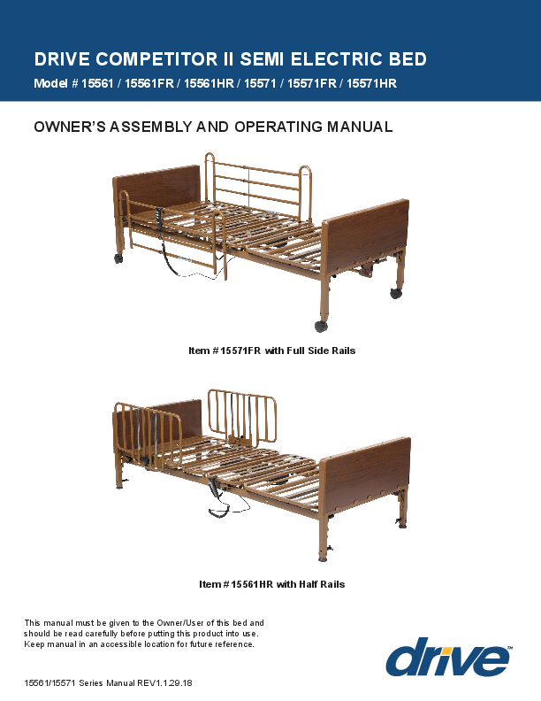
DRIVE COMPETITOR II SEMI ELECTRIC BED
Model # 15561 / 15561FR / 15561HR / 15571 / 15571FR / 15571HR
OWNER'S ASSEMBLY AND OPERATING MANUAL
Item # 15571FR with Full Side Rails
Item # 15561HR with Half Rails
This manual must be given to the Owner/User of this bed and should be read carefully before putting this product into use. Keep manual in an accessible location for future reference. 15561/15571 Series Manual REV1.1.29.18

TABLE OF CONTENTS
Standard Symbols & Warning Labels................................................................................................. 1-3 Intended Use & General Safety........................................................................................................... 4-6 Electromagnetic Emmissions & Immunity....................................................................................... 7-10 Technical Specifications........................................................................................................................11 Packaging and Handling....................................................................................................................... 12
Unpacking......................................................................................................................................... 12 Inspection.......................................................................................................................................... 13 Storage............................................................................................................................................. 13 Assembly Instructions.......................................................................................................................... 14 Frame Assembly............................................................................................................................... 15-17 Motor Installation .................................................................................................................................. 18 Method A - Side Installation......................................................................................................... 19-21 Method B � Underneath installation............................................................................................. 22-24 Bed Operation .................................................................................................................................. 25-26 Bed Rail Installation......................................................................................................................... 27-29 Manual Hi/Lo Adjustment Crank & Manual Leg Adjustment........................................................ 30-31 Accessories...................................................................................................................................... 32-33 Maintenance & Safety Checks........................................................................................................ 34-35 Warnings........................................................................................................................................... 36-37 Troubleshooting.................................................................................................................................... 38 Appendix: A Guide to Bed Safety Bed Rails.................................................................................. 39-40
NOTE: DO NOT operate this product without first reading and understanding this user manual. Damage or injury may result from improper use of this product.

STANDARD SYMBOLS USED IN THIS MANUAL
This manual includes important information about the safety of personnel and equipment. As you read through this manual be aware of the symbols and their meanings.
! DANGER
Information that appears under the DANGER symbol concerns the protection of personnel from direct and pending hazards that, if not avoided, will result in immediate, serious personal injury or death in addition to damage of the equipment.
DANGER SHOCK HAZARD Information that appears under the DANGER SHOCK HAZARD symbol concerns the protection of personnel from possible hazards related to electrical shock.
FIRE HAZARD Information that appears under the FIRE HAZARD symbol concerns the protection of personnel from possible hazards related to fire and flammability.
! WARNING
Information that appears under the WARNING symbol concerns the protection of personnel from possible hazards that can result in injury or death in addition to damage of the equipment.
! CAUTION
Information that appears under the CAUTION symbol concerns the protection of personnel from possible hazards that may result in minor injury or damage of the equipment.
CRUSH HAZARD Information that appears under the CRUSH HAZARD symbol concerns the protection of personnel from possible hazards related to reduce clearances.
NOTE: Information that appears with the NOTE text gives added information, which helps in understanding the item being described.
1

PRODUCT SYMBOLS

Symbols

Description

Symbols

IPX4

Type BF applied part equipment. IEC 60601-2-52: The applied part includes all parts of the medical bed that are within reach of the patient, even if they are underneath the mattress support surface. Applied parts list: Mattress, Bed frame, Side Rail, Head Board and Foot Board, Mattress retainer.

According to IEC 60529. Rating for dustprotection and identified as equipment that is protected against splashing water.

IEC 60601-2-52 IEC 60601-1 IEC 60601-1-2 IEC6060-1-1-11

Class II equipment

Description Recycle the item in accordance with local regulations.
A product bearing the IEC listed Mark is determined to have met the minimum requirements of prescribed product safety standards.

The owner's manual needs to be read before operating the bed.

Maximum patient weight and safe working load

PRODUCT HANDLING SYMBOLS
Do not remove motor cover or repair yourself. Contact your local Provider or Dealer for technical assistance.

5

Do not stack more than 5 cartons high

Do not step

Keep Dry
Do not exceed 104 degrees F
104oF 40oC
Do not leave in direct sun light for extended period of time
Handle with care

2

WARNING LABELS
3

INTENDED USE
The Drive #15561/15571 series beds are intended for use within a Homecare environment, Application Environment 4 (i.e.: care provided in a domestic area where ME Equipment is used to alleviate or compensate for an injury, disability or disease).
This bed is NOT intended for patient/resident transport. Wheels are provided only to allow movement within the patient/ resident room for cleaning or patient/resident access.
CONTRA-INDICATIONS
This bed should not be operated (control the movements of the bed through the control interfaces)by persons who do not have the cognitive skills to understand the information in the owner's manual or cannot understand and perform the proper operation of the bed. This bed should not be used or operated by children.

GENERAL SAFETY
NOTE: In this manual, the terms patient and resident refer to a resident in a homecare environment.

! WARNING
� NEVER allow anyone under the bed at any time.
� DO NOT let any body parts protrude over the side or between parts, especially when the bed is being operated.
� This bed should not be placed in an oxygen enriched environment.
� Unplug bed or stop pressing pendant button when bed does not function as expected.
� DO NOT operate this product without first reading and understanding this user manual. Damage or injury may result from improper use of this product.
� Possible injury or Death may occur if accessories are not provided by Drive DeVilbiss Healthcare. Please contact Drive DeVilbiss Healthcare for accessories that are compatible with this bed.
� Possible injury or Death may occur if replacement parts are not provided by Drive DeVilbiss Healthcare. Please contact Drive DeVilbiss Healthcare for replacement parts compatible with this bed.

! WARNING

� Power cord must be plugged into appropriate wall outlet, ensuring it can be unplugged easily in case of an emergency.

� Never permit more than one (1) person in/on the bed at any time. Never exceed the weight capacity of this bed. The weight capacity of this bed is 450lbs (205kg) including accessories and options (not all accessories and options can be used at the same time). Once resident's weight is known (X), subtract that from 450 lb total weight capacity (Y) and remainder is allowable weight for mattress, accessories and optional equipment (Z). (Z = Y � X)

Assumes:

Max Patient/resident Weight

350 lbs (158.76 kg)

Full or Half Rails (avg/pair)

25 lbs (11.34 kg)

Mattress weight (avg)

25 lbs (11.34 kg)

Trapeze

26 lbs (11.79 kg)

� The medical bed should be left in its lowest position except when care is being provided in order to reduce risk of injury due to falls.

� The bed MUST be connected to an appropriate power source. Unless equipped with battery backup, this bed will not operate when not plugged in. Mains cable and proper function must be checked regularly.

� Possible Injury or Death may occur if bed is pushed over abrupt thresholds while bed is occupied. This bed is not intended for patient/resident transport. Please use an approved resident transport device when moving a resident.

4

DANGER SHOCK HAZARD
� DO NOT plug anything into the control box of bed (i.e. pendants and actuators) while mains cable (power cord) is plugged into the wall outlet.
� Any cords or tubing used on or with this bed MUST be routed and secured properly to ensure that they do NOT become entangled, kinked or severed during normal operation of the bed.
� DO NOT roll the bed over any power or pendant cords. � DO NOT open any actuators, control boxes, or pendants. Service and repair must only to be performed by authorized
service personnel. If unauthorized service is performed on any components the warranty is void. � Inappropriate handling of power supply cords can create a shock hazard. � When routing cables from other equipment in the medical bed, precautions shall be taken to avoid squeezing those
between parts of the medical bed. � DO NOT allow the cord, electrical outlets, and electrical control box or hand pendant to become wet or submerged. � DO NOT operate the bed if any electrical component such as the power cord, electrical outlet, connections, motor/
actuator or mechanical component has malfunctioned or has been damaged in any way. � The bed MUST be connected to an appropriate power source. Unless equipped with the optional battery backup,
this bed will not operate when not plugged in. Mains cable and proper function must be checked regularly. � Possible injury or Death may occur due to pendant cord being a source for entangling patient/resident. Patients/
residents with decreased mental acuity should NOT have access to pendant.
FIRE HAZARD � DO NOT use near open flame or explosive gases. � Possible Fire Hazard if used with nasal mask in 1/2 bed tent 02 administering equipment. If 02 tent is being used it
should not fall below the mattress deck. The pendant should not be placed in an oxygen enriched environment such as an 02 tent. � This bed should not be placed in an oxygen enriched environment.
! CAUTION
� This medical bed is not intended to work with patient lifts other than those specified by Drive DeVilbiss Healthcare as being compatible.
� Do NOT use side rails as handles for moving the bed. � Keep all moving parts, including the mattress deck (sleep surface), main frame, all drive actuators and moving
components free of obstructions. � Ensure that the individual using this bed is properly positioned, particularly when the bed is being operated. � Body weight should be evenly distributed over the sleeping surface of the bed. Avoid situations where entire body
weight is on a raised head or foot surface. This includes while assisting the resident in repositioning or transferring in or out of bed. � Supervision is required when this product is operated by or near children or people with disabilities. � Do not modify this bed without authorization of the manufacturer. If unauthorized service is performed on any components the warranty is void. � This bed frame complies with EMC requirements of IEC 60601-1-2. Radio transmitting equipment, cell phones or similar electronic devices, used in proximity of the bed, may affect the beds performance.
5

!

CRUSH HAZARD

� Possible crush hazard exists between the bed deck and frame. Keep hands and feet out from under the bed deck at all times while operating the bed.

� Possible Injury may occur when lowering or raising the bed. Keep feet and hands clear of bed frame.

� Do not put your hands/fingers into the opening of head or thigh deck edges, crush point may cause injury to your hands/fingers.

! ENTRAPMENT WARNING
� The entrapment issues can still arise when components and accessories are not properly installed.
� If a resident/patient's mental or physical condition could lead to resident/patient entrapment, the mattress deck (sleep surface) should be left in the flat position when unattended. Failure to do so could result in injury or death.
� Incompatible mattress and side rails can create hazards. Only compatible Drive DeVilbiss Healthcare side rails may be used on this bed. Make sure mattress is the correct size for bed frame and the Side rails are secured to frame to decrease the risk of entrapment.
� If bed frames have been serviced or any other adjustments have been made, you must ensure all parts are securely back in place before operating the bed.

! WARNING
Incompatible mattress and side bars/rails can create hazards. Read instructions for use.

MATTRESS SPECIFICATIONS
! WARNING
Possible ENTRAPMENT Hazard may occur if you do not use the recommended specification mattress.
Resident entrapment may occur leading to injury or death.
� A mattress may not be included with this bed. It is recommended that a standard 36" wide mattress that is made to fit an 80"or 84" (extension) length bed frame is used, such as a Drive DeVilbiss Healthcare standard inner spring, foam, fiber, or pressure redistribution mattress. Mattress height must be a minimum of 5-1/2 inches and a maximum of 7 inches.
� Also available are Drive DeVilbiss Healthcare's assortment of mattress overlays and Low Air Loss flotation mattress systems.

6

ELECTROMAGNETIC EMMISSION AND IMMUNITY
This MEDICAL ELECTRICAL EQUIPMENT needs special precautions regarding EMC and needs to be installed and put into service according to the EMC information provided in the table below. Portable and mobile RF communications equipment can affect MEDICAL ELECTRICAL EQUIPMENT

! WARNING
The use of ACCESSORIES, transducers and cables other than those specified, with the exception of transducers and cables sold by the manufacturer of the EQUIPMENT or SYSTEM as replacement parts for internal components, may result in increased EMISSION or decreased IMMUNITY of the EQUIPMENT or SYSTEM.
Below cables information are provided for EMC reference

Cable AC Power Line

Max. cable length, Shielded/unshielded

3.8m

Unshielded

Number 1 Set

Cable classification AC Power

Signal Line

3.2m

(from remote control part

to be main body)

Unshielded

1 Set

DC Power

! WARNING
Important information regarding Electro Magnetic Compatibility (EMC)
SEMI ELECTRIC BED WITH MANUAL LEG ADJUST requires special precautions regarding EMC when put into service according to the EMC information provided in the user manual; SEMI ELECTRIC BED WITH MANUAL LEG ADJUST conforms to this IEC 60601-1-2:2014 standard for both immunity and emissions. Nevertheless, special precautions need to be observed:
SEMI ELECTRIC BED WITH MANUAL LEG ADJUST with no ESSENTIAL PERFORMANCE is intended for use in a professional healthcare facility environment and homecare environment.
WARNING: Portable RF communications equipment (including peripherals such as antenna cables and external antennas) should be used no closer than 30 cm (12 inches) to any part of the SEMI ELECTRIC BED WITH MANUAL LEG ADJUST, including cables specified by the manufacturer. Otherwise, degradation of the performance of this equipment could result."
The use of accessories and cables other than those specified by Drive DeVilbiss Healthcare, with the exception of accessories and cables sold by Drive DeVilbiss Healthcare for use with the SEMI ELECTRIC BED WITH MANUAL LEG ADJUST as replacement parts for internal components, may result in increased EMISSIONS or decreased IMMUNITY of the SEMI ELECTRIC BED WITH MANUAL LEG ADJUST.
WARNING: Use of this equipment SEMI ELECTRIC BED WITH MANUAL LEG ADJUST adjacent to or stacked with other equipment should be avoided because it could result in improper operation. "

7

EMI COMPLIANCE TABLE
Table 1 - Emisson

Phenomenon

Compliance

RF emissions

CISPR 11 Group 1, Class B

Electromagnetic environment
Professional healthcare facility environment and homecare environment

Table 2 - Enclosure Port Phenomenon

Basic EMC standard

Electrostatic Discharge
Radiated RF EM field

IEC 61000-4-2 IEC 61000-4-3

Proximity fields from RF wireless communications equipment
Rated power frequency magnetic fields

IEC 61000-4-3 IEC 61000-4-8

Immunity test levels Professional healthcare facility environment and homecare environment �8 kV contact �2kV, �4kV, �8kV, �15kV air 10V/m 80MHz-2.7GHz 80% AM at 1kHz Refer to table 3
30A/m 50Hz or 60Hz

Table 3 - Proximity fields from RF wireless communications equipment

Test frequency (HHz)
385 450 710 745 780 810 870 930 1720 1845 1970 2450 5240 5500 5785

Band (MHz) 380-390 430-470 704-787
800-960
1700-1990
2400-2570 5100-5800

Immunity test levels Professional healthcare facility environment and homecare environment Pulse modulation 18Hz, 27V/m FM, �5kHz deviation, 1kHz sine, 28V/m Pulse modulation 217Hz, 9V/m
Pulse modulation 18Hz, 28V/m
Pulse modulation 217Hz, 28V/m
Pulse modulation 217Hz, 28V/m Pulse modulation 217Hz, 9V/m

8

Table 4 - Input AC power Port

Phenomenon

Basic EMC standard

Electrical fast transients/burst
Surges Line-to-line

IEC 61000-4-4 IEC 61000-4-5

Conducted disturbances IEC 61000-4-6 induced by RF fields

Voltage dips

IEC 61000-4-11

Voltage interruptions

IEC 61000-4-11

Immunity test levels Professional healthcare facility environment and homecare environment
�2 kV 100kHz repetition frequency �0.5 kV, �1 kV
3V, 0.15MHz-80MHz 6V in ISM bands and amateur radio bands between 0.15MHz and 80MHz 80%AM at 1kHz 0% UT; 0.5 cycle At 0�, 45�, 90�, 135�, 180�, 225�, 270� and 315� 0% UT; 1 cycle and 70% UT; 25/30 cycles Single phase: at 0�
0% UT; 250/300 cycles

Table 5 � Signal input/output parts Port

Phenomenon

Basic EMC standard

Electrical fast transients/ burst
Conducted disturbances induced by RF fields

IEC 61000-4-4 IEC 61000-4-6

Immunity test levels
Professional healthcare facility environment and homecare environment
�1 kV 100kHz repetition frequency 3V, 0.15MHz-80MHz 6V in ISM bands and amateur radio bands between 0.15MHz and 80MHz 80%AM at 1kHz

9

! ELECTRICAL SAFETY WARNINGS
A safety feature of this product includes protection against overheating caused by excessive or extended periods of operation. Depending on the duration, this includes multiple or repeated adjustments or the use of multiple functions at one time. To ensure trouble free operation, always allow a slight pause between multiple adjustments and avoid pressing more than one function button at a time. If thermal protection activation should occur, the bed will not respond to pendant commands. Given this situation, release the pendant button and allow the bed unit to sit for several minutes. This will allow the protection function time to reset and restore bed function. Depending on severity of the initial overheating, this could take up to 30 minutes.
Allow a slight pause between adjustments and avoid pressing multiple buttons at the same time. If pendant buttons are depressed too rapidly or multiple buttons are pressed at the same time, the desired feature may not activate. Simply release the pendant button, permit a slight pause and then activate the next operation.
Always unplug the bed from the electrical outlet before cleaning.
DO NOT open assemblies such as the motors, motor housing or pendant. No user serviceable parts are inside. Only qualified technicians are permitted to repair these parts. If unqualified individuals perform any work on these beds, the warranty is void.
DO NOT place pendant under or between objects. This may unintentionally press the buttons and may cause injury or damage.
Electronic equipment may be influenced by Radio Frequency Interference (RFI). Caution should be exercised with regard to the use of portable communications equipment in the area around such equipment. If RFI causes erratic behavior, unplug the electric bed IMMEDIATELY. Leave unplugged while transmission is in progress.
Ensure all cables and cords are routed such that they will not become entangled or pinched. Otherwise damage or injury may result.
If a button on the pendant sticks or does not release and/or one of the functions will not stop moving. Unplug the power cord from the electrical supply outlet and take the bed out of service for repair.
If a liquid is spilled in or around the electric bed, unplug the electric bed before cleaning. Clean up the spill and allow the electric bed or the area around the electric bed to dry thoroughly before using the electric controls again.
Inspect the covering of the hand pendant panel to assure that the covering is not cracked or damaged.
Keep all electrical cords away from heated or hot surfaces.
Keep the cord away from heated surfaces.
NEVER operate this bed if it has a damaged cord or plug, if it is not working properly, if it has been dropped, damaged, or dropped into water. Return the bed to a service center for examination and repair.
On Full Electric beds, the Hi/Lo crank MUST be removed before the bed is used. Failure to remove the crank may cause damage or personal injury.
Refer servicing to qualified personnel only. Grounding reliability depends upon a properly grounded wall outlet.
The pendant and power cords must be routed and secured properly to ensure that the cords DO NOT become entangled, pinched and/or severed during operation of the electric bed.
Unplug from the outlet before servicing. Unplug the power cord from its power source before performing any maintenance on the manual/electric bed.
Use caution when disconnecting the pendant. DO NOT press pendant buttons.
When bed is not to be used for an extended period, unplug electric bed from the wall outlet.
When using an extension cord, use an extension cord having at least 16 AWG (American Wire Gauge) wire and the same or higher electrical rating as the device being connected. Use of improper extension cord could result in a risk of fire and electric shock.
When using nasal or masked type oxygen administering equipment, the oxygen or air tubing MUST be routed and secured properly to ensure that the tubing does not become entangled and/or severed during normal operation of the bed.
DO NOT use near explosive gases.
Possible fire hazard when used with oxygen administering equipment other than nasal or masked type.
Use masked or nasal type oxygen administering equipment only in conjunction with this bed. The use of ANY other type of oxygen administering equipment can result in a fire hazard.
10

TECHNICAL SPECIFICATIONS

Overall Length Overall Width w/o Rails Overall Width w/Rails Length & Width of Mattress Deck Maximum Weight Capacity Head Deck Angle Foot Deck Angle Height Range
Manual Bed Ends Crank Bed Ends Under Bed Clearance Manual Bed Ends Crank Bed Ends Total Product Weight Head Section Foot Section Manual Bed Ends Crank Bed Ends Noise Level Electrical Requirements
Rated Current Input Fuse Specification Duty Cycle Battery Backup: Handset (1) & Motor (2) Relative Humidity Recommended Storage &Shipping Temperature Recommended Operating Temperature Atmospheric Pressure Range

87.2" 35.63" 37" 79.73" x 34.65" 450lbs. includes all accessories 0�to 68� 0�to 30�
11" to 20" 15.1" to 22.5"
4.4" 8.3"
41lbs 41lbs 44lbs 52lbs 65dB(A) 120VAC,60Hz 1.8A max 2A 250V T_On 2 Min / T_Off 18 Min 9V 15% to 93% relative humidity, non-condensing -22�F to +158�F 41�F to 104�F 700hPa to 1060hPa

OPERATING TEMPERATURE
If bed has been stored in an area where the temperature is above or below the Recommended Operating Temperature range of 41�F to 104�F. You must wait at least 30 minutes for the bed temperature to adjust to the Recommended Operating Temperature range of 41�F to 104�F before use.
BED SERIAL NUMBERS
When ordering parts or when contacting Drive DeVilbiss Healthcare Customer Service Department, please include bed's model and serial numbers, found on the identification labels as below. The identification labels are located under the sleep deck on the either side of the bed frame.
COMPLIANCE INFORMATION
Matching the correct bed components to meet regulatory specifications can be complicated. Drive DeVilbiss Healthcare offers a wide variety of compliance options and we can assist your facility in selecting components or accessories that are recommended for the specific bed model.

11

PACKAGING / HANDLING

TOOLS REQUIRED � Wire Cutters

� Utility Knife

! CAUTION
Unpack the bed in an area with sufficient room to work. Do not allow residents/patients near the bed until it has been completely set up and the work area has been cleared of all debris.
UNPACKING 1. Check cartons for any obvious damage to packaging or contents. If damage is evident, contact your local Drive
Medical dealer/provider.
2. Remove any loose packaging from the cartons.
3. Carefully remove all components from the cartons.

Component Item#
15561HF 15571HF 15565FM 15561FRAIL 15561HRAIL

Description
Competitor II Manual Adjustment Bed Ends, 1/PR Competitor II Crank Hi/Lo Bed Ends w/Driveshaft, 1/PR Competitor II Head/Foot Frame w/MTR, 1/EA Competitor II Full Rail ONLY, 1/PR Competitor II Half Rail ONLY, 1/PR

Shipping Weight (LBS)
46
60
102
20
20

Length (inch)
37 38 35 35 19

Width (inch)
5 6 9 3 5

Height (inch)
27 26 47 22 34

Bed/Bed PKG Item # 15571 15571FR
15571HR
Bed/Bed PKG Item # 15561

#15571 Series: Bed Description & Component Configuration

Competitor II Crank Hi/Lo Height Adjust Bed, 1/cs

15571HF

Competitor II Crank Hi/Lo Bed Ends w/Driveshaft, 1/PR

15565FM

Competitor II Head/Foot Frame w/MTR, 1/EA

Competitor II Crank Hi/Lo Height Adjust Bed w/Full Rail, 1/cs

15571HF

Competitor II Crank Hi/Lo Bed Ends w/Driveshaft, 1/PR

15565FM

Competitor II Head/Foot Frame w/MTR, 1/EA

15561FRAIL

Competitor II Full Rail ONLY, 1/PR

Competitor II Crank Hi/Lo Height Adjust Bed w/Half Rail, 1/cs

15571HF

Competitor II Crank Hi/Lo Bed Ends w/Driveshaft, 1/PR

15565FM

Competitor II Head/Foot Frame w/MTR, 1/EA

15561HRAIL

Competitor II Half Rail ONLY, 1/PR

#15561 Series: Bed Description & Component Configuration

Competitor II Manual Height Adjust Bed, 1/cs

15561HF

Competitor II Manual Adjustment Bed Ends, 1/PR

15565FM

Competitor II Head/Foot Frame w/MTR, 1/EA

12

15561FR 15561HR

Competitor II Manual Height Adjust Bed w/Full Rail, 1/cs

15561HF

Competitor II Manual Adjustment Bed Ends, 1/PR

15565FM

Competitor II Head/Foot Frame w/MTR, 1/EA

15561FRAIL

Competitor II Full Rail ONLY, 1/PR

Competitor II Manual Height Adjust Bed w/Half Rail, 1/cs

15561HF

Competitor II Manual Adjustment Bed Ends, 1/PR

15565FM

Competitor II Head/Foot Frame w/MTR, 1/EA

15561HRAIL

Competitor II Half Rail ONLY, 1/PR

INSPECTION
1. Examine each component carefully for damage, scratches, dents or any other visual damage. 2. Carefully remove Tie Wraps holding power cord, hand pendant and drive shaft. 3. Inspect power cord and plug for cuts or damage. 4. Inspect the motors for damage, loose connections, cuts or damage to the wires. 5. Ensure motor connection to pendant are connected correctly and secure.
STORAGE 1. If the bed is not assembled immediately, retain cartons and packaging for storage until assembly is completed. 2. Store the packaged bed in a dry area. 3. DO NOT place other objects on top of the packaged bed cartons.

13

ASSEMBLY INSTRUCTIONS
1. Confirm that all parts are present: A. Foot Deck Section B. Head Deck Section C1. Crank Hi/Lo Head & Foot Boards (15571HF) C2. Manual Adjust Head and Foot Boards (15561HF) D. Casters (4) � 2 locking, non-locking (15571 Series Only) E. Hand Crank (15571 Series Only) F. Hi/Low Drive Shaft (15571 Series Only) G. Head/Foot Deck Section Motors with Hand Control
B ED

C1 F

A

C2

G F
Caution: DO NOT attempt to operate bed controls until completion of assembly as damage to bed components and/or personal injury may occur.
14

FRAME ASSEMBLY
2.Place both ends of the frame/sleep surface on their side and align the flange with the receptacle as shown.
15

3.To attach the head and foot sections, slide the two sides together and lock into position with cotter pin and clasp.
To disassemble the head and foot section, remove cotter pin and clasp and seperate sections.
16

4.Secure the frame/sleep surface with the cotter pin as shown (Figure A). Lock the cotter pin with the attached clasp. Repeat on the opposite side (Figure B).
Figure A
Figure B 17

THERE ARE TWO METHODS FOR THE INSTALLATION OF THE MOTOR
5. NOTE: Before installing motor, ensure plug hand pendant cable is plugged into motor as shown
6. To install motor, remove locking caps on top of the motor.
METHOD A
The motor is installed on the bed frame when the frame is standing on its side. Installation instructions can be found on pages 20-22. Labels on motor indicate which end goes toward Head Section & Foot Section.
Method B
The motor is installed from underneath the bed frame (horizontal to the ground) Installation instructions can be found on pages 23-25. Labels on motor indicate which end goes towards Head Section & Foot Section.
18

METHOD A Installation of the motor when bed frame is on its side

A1. Prior to installation, make sure that the 2 white motor blocks are in the retracted position. If the white motor block is not in the retracted position, plug power cord into power outlet and retract motor block by depressing the down buttons on hand pendant until motor block is fully retracted.

CORRECT

INCORRECT

Actuator Bar Flange

A2.Align the opening on the head end of the motor with the flange on the head section of the bed and insert the flange into the motor compartment.
A3.With the palm of your hand, snap the motor flush to the actuator bar.

A4.Align the opening on the foot end of the motor with the flange on the foot section of the bed and insert the flange into the motor compartment.
A5.With the palm of your hand, snap the motor flush to the actuator bar.
19

A6. Once in place, replace the motor covers to secure the motor.
A7.Assemble Bed Ends to Frame: #15571HF for Crank Hi/Lo Beds Ends or #15561HF for Manual Adjustment Bed Ends. Once the motor is attached, lay bed flat and install head and foot boards. Foot end of the bed frame has the mattress retainer. Lift mattress retainer to help keep mattress in place. Gear box crank connection will always face outward � away from the bed.
Install casters onto 15571HF Bed ends by inserting the stem of the caster into the leg receptacle. It is recommended to install one locking caster and one non-locking caster on each bed end. The locking casters should be installed diagonally from each other. Install casters to both bed ends. To engage locking caster, press down on locking tab; lift up to release. 15561HF bed ends do not include casters, casters are an option.
Attach the 15571HF or 15561HF Head and Foot Boards by aligning the frame mounting hooks over bed end mounting pins and push frame down to secure in place. Push Slide Locks in place over frame hooks for both bed ends to help prevent frame separation from bed ends.
20

NOTE: # 15571HF Crank Hi/Lo Head and Foot Boards are the same height and must be assembled as a set in order for Bed Ends to operate correctly. Note position of the embossed "HEAD" and "FOOT" labels on top and sides of the bed ends for proper assembly. Foot end of the bed frame has the mattress retainer. Lift mattress retainer to help keep mattress in place. Gear box crank connection will always face outward � away from the bed.
#15561HF Manual Adjust Head and Foot Boards are the same height and are interchangeable with each other.
A8. The #15571 Hi/Lo Drive Shaft comes in 3 sections. Assemble the Hi/Lo Drive Shaft by inserting the (A) section with push pin into the (B) section with indicators and align with the "Semi" indicator hole. Next extend the (C) section and align with the single hole location opposite the "Semi" indicator hole location.

B

A

C

�Slide Driveshaft under length of the bed. Lift the Head Section of the bed frame and install the Spring Loaded end of the Hi/Lo Drive Shaft to the Foot Board drive pin, then install head end of the Hi/Lo Drive Shaft to the Head Board drive pin.
� Hi/Lo Drive Shaft is spring loaded so it will fit securely between these two points. � Adjust length of Hi/Lo Drive Shaft if it is too long or too short.

21

METHOD B
B1.Assemble 15571HF or 15561HF Hi/Lo Bed Ends to the Frame. Install casters onto 15571HF Bed ends by inserting the stem of the caster into the leg receptacle. It is recommended
to install one locking caster and one non-locking caster on each bed end. The locking casters should be installed diagonally from each other. Install casters to both bed ends. To engage locking caster, press down on locking tab; lift up to release. 15561HF bed ends do not include casters, caster are an option.
Lay bed flat and install head and foot boards. Attach the Head and Foot Boards by aligning the frame mounting hooks over bed end mounting pins and push frame down to secure in place. Push Slide Locks in place over frame hooks for both bed ends to help prevent frame separation from bed ends. NOTE: # 15571HF Crank Hi/Lo Head and Foot Boards are the same height and must be assembled as a set in order for
Bed Ends to operate correctly. Note position of the embossed "HEAD" and "FOOT" labels on top and sides of the bed ends for proper assembly. Foot end of the bed frame has the mattress retainer. Lift mattress retainer to help keep mattress in place. Gear box crank connection will always face outward � away from the bed.

B2. The #15571 Hi/Lo Drive Shaft comes in 3 sections. Assemble the Hi/Lo Drive Shaft by inserting the (A) section with push pin into the (B) section with indicators and align with the "Semi" indicator hole. Next extend the (C) section and align with the single hole location opposite the "Semi" indicator hole location.

B

A

C

A-B

C

22

�For 15571, slide Driveshaft under length of the bed. Lift the Head Section of the bed frame and install the Spring Loaded end of the Hi/Lo Drive Shaft to the Foot Board drive pin, then install head end of the Hi/Lo Drive Shaft to the Head Board drive pin.
� Hi/Lo Drive Shaft is spring loaded so it will fit securely between these two points.
� Adjust length of Hi/Lo Drive Shaft if it is too long or too short.

B3. Prior to installation, make sure that the 2 white motor blocks are in the retracted position. If the white motor block is not in the retracted position, plug power cord into power outlet and retract motor block by depressing the down buttons on hand pendant until motor block is fully retracted.

CORRECT

INCORRECT

B4.Remove the covers from the motor and place under the bed and aligned with the actuator under the head section. There are labels on the motor that provide direction and placement in relation to the head section.

23

B5.With both hands, lift the motor and insert into the actuator and frame as shown. With the palm of your hand snap the motor flush to actuator bar.
B6. Once in place, replace the motor covers to secure the motor by sliding cover over motor guides to secure the actuator bar.
24

BED OPERATION
CRUSH HAZARD Crush point exists due to LOW BED CLEARANCE. Do NOT place feet or other limbs under the frame when lowering the bed. When lowering the bed, be aware this may cause INJURY if limbs or personal items interfere with bed movement. Stay clear of the frame and ensure children and/or pets are not under the bed before lowering. WARNING
� It is critically important to lock all casters to prevent unintended bed movement. � Possible injury or Death may occur due to pendant cord being a source for entangling patient/resident.
Patients/residents with decreased mental acuity should NOT have access to pendant.
! WARNING
When routing cables from other equipment in the medical bed, precautions shall be taken to avoid squeezing between parts of the medical bed.
OPERATION
The Model #15571 & 15561 Semi-Electric Bed comes with a 3 Function hand held Pendant. � Top Buttons control raising and lowering the Head Section; � Middle Buttons control raising and lowering the Foot Section; � Lower Buttons simultaneously control the raising and lowering of the Head and Foot Sections.� � Green indicator will illuminate when buttons are depressed.
25

HAND CONTROL
The Competitor II bed comes with a hand control that will illuminate when the bed is plugged into a grounded or polarized wall outlet, or with 9V battery (not included) installed in the hand control. The hand control will illuminate as long as the wall outlet or battery has power. A single 9 volt battery can be installed into the back of the Hand Held Pendant and that will allow the head and foot sections to be lowered at a very slow speed. With this battery installed, the motor can be operated to return the sleep surface to the horizontal position in the event of a power failure.

! WARNING
� The battery backup should be used for EMERGENCY PURPOSES ONLY. � DO NOT use the battery backup to demonstrate or display a bed. � Battery function should be checked periodically to insure battery health. The battery should be removed if it no longer
has a charge or if leakage from battery occurs. � Drive DeVilbiss Healthcare cannot be held responsible for improper backup use. � When battery is installed, unplugging the bed from mains power will not switch bed off. � Batteries must be properly disposed of in accordance with local regulations.
PENDANT LOCKOUT FEATURE
Push button to lock & unlock pendant controls. When light is on pendant is operating.

Lockout Feature Raise Head Section Raise Foot Section Raise Head/Foot Section

Indicator will light when buttons depressed Lower Head Section
Lower Foot Section
Lower Head/Foot Section

26

SIDE RAIL INSTALLATION (OPTION)
! SIDE RAIL WARNING
Other manufacturers side rails/bars may not be compatible and can lead to entrapment issues or harm to patients/ residents. Only compatible side rails/bars may be used on this bed. Make sure bed frame is adjusted correctly for mattress size being used and side rails/bars are properly secured to frame to decrease the risk of entrapment.
! ENTRAPMENT WARNING
The risks associated with these devices used in conjunction with specialty mattresses and mattress overlays have not been evaluated. When these specialty mattresses or mattress overlays are used, the end user facility must take steps to ensure that the therapeutic benefit outweighs the risk of entrapment.
! SIDE RAIL WARNING
Side rails/bars serve as a passive reminder to help keep patient from falling out of the bed.
CRUSH HAZARD Crush hazard exists between the side rails/bars and the floor when in the lowest position which may cause injury to oneself or others. Do NOT place feet beneath the side rails/bars.
! SIDE RAIL WARNING
Although side rails are not rated to any specific weight limitation, the side rails may become deformed or broken if excessive side pressure is exerted on the bed rails. The side rail is not an assist device for getting into or out of bed.
DO NOT use the side rails as push handles when moving the bed. Always test to make sure that the side rails are properly and securely in place before using the bed.
DO NOT install the optional side rails without reading and understanding all of the instructions in the instruction sheet that accompanies the bed rail kit.
DO NOT use the side rails as push handles for moving the bed.
Side rails are intended to prevent an individual from inadvertently rolling out of bed. DO NOT use for restraint purposes.
When used with a manual/electrical bed, side rails DO NOT fall under any weight limitations. Side rails can be deformed or broken if excessive side pressure is exerted on the bed rails. Side rails are used for the purpose of preventing an individual from inadvertently rolling out of bed. Side rails are NOT intended nor may be used for restraint purposes. If an individual is capable of injuring himself/herself, a physician or a healthcare professional should be consulted for alternative means of safe restraint.
! ENTRAPMENT WARNING
Accurate assessment of the patient/resident and monitoring of correct maintenance and equipment use are required to prevent entrapment. For additional information on product and safety issues for bed frames and rails refer to product manuals specific to the product or accessories you have or are planning to install. If bed frames have been serviced or any other adjustments have been made, you must ensure all parts are securely back in place before operating the bed. Other manufacturers side rails may not be compatible and can lead to entrapment issues or harm to residents and staff. Make sure mattress is the correct size for bed frame and the Side rails are secured to frame to decrease the risk of entrapment.
On March 10, 2006, the U.S. Food and Drug Administration (FDA) released guidelines for reducing the risk of hospital bed entrapment entitled; "Hospital bed System Dimensional and Assessment Guidance to Reduce Entrapment". This guidance document identifies potential entrapment areas within the bed frame, rails and mattress and identifies those body parts most at risk for entrapment. It also provides manufacturers with basic design criteria to consider when
27

developing hospital/convalescent beds; recommends specific test methods to assess the conformance of existing hospital/convalescent bed systems; and answers frequently-asked questions about entrapment issues. The FDA Guidance document identifies specific dimensional criteria on potentially injury-threatening gaps and spaces that can occur between bed system components, such as side rails when improperly installed. Drive DeVilbiss Healthcare's 15561/15571 beds and approved accessories are manufactured to be in conformance with these guidelines. Please be aware that entrapment issues can still arise when components and accessories are not properly installed on the bed. It is important for the provider or facility staff to recognize they have an equal role in complying with the FDA guidelines to help ensure resident safety and avoid injuries.
Copies of this document can be obtained from the FDA website: http://www.fda.gov/medicaldevices/deviceregulationandguidance/guidancedocuments/ucm072662.htm
BED RAIL ASSEMBLY
Full Bed Rails: To install Full Bed Rails, lift the head section and find the rail receptacle located on the frame of the bed as shown (Fig A). Pull receptacle outward and return head section to the flat position. Turn receptacle in a vertical position to receive the rail (Fig B). Repeat for all four rail receptacles.

A

B

Full Bed Rail Operation: Pull out Pull Pin on each bracket one at a time to raise or lower rail. Ensure Pull Pins are properly engaged to lock rails in position.
28

Half Bed Rails: To install half rails, locate the label located on the head section of the frame (Fig D). The half rail clamp should be installed over this label. Align fixed clamp jaw (Fig E) in front of bed frame rail as shown below. Align movable clamp jaw on top of bed frame rail, and turn knob clockwise until clamp is tight, securing safety rail to bed frame rail (Fig F).

D

E

F

Half Bed Rail Operation: Pull out Pull Pin on each bracket to raise or lower rail. Ensure Pull Pin is properly engaged to lock rail in position.
NOTE: Bed rails should be removed when bed is disassembled to help prevent damage.

CORRECT
When installing bed rail, only place one (1) rail on bed per side.

INCORRECT
DO NOT place 2 bed rails on the same side of the bed as shown above.

WARNING - INCORRECT MOUNTING MAY CAUSE INJURY OR DEATH

29

MATTRESS RETAINER ADJUSTMENT
Before a mattress is placed onto the bed deck, flip up the mattress guard to reduce mattress movement
15571HF HI/LO ADJUSTMENT CRANK
Use hand crank to raise or lower the entire bed. Insert Hand Crank into bed end gear box and turn to adjust bed height.
30

15561 MANUAL ADJUST HEAD & FOOT BOARDS
#15561HF Manual Adjust Head & Foot Boards have two height adjustments. Adjustment #1 is located on the bed end frame that allows for an upper and lower deck height position. Adjustment #2 is located on the Bed End leg itself and allows for High, Medium and Low Leg Height positions. Using both of these adjustments will provide maximum high and low height positioning.

High Deck Height Position: 20"

Low Deck Height Position: 11"

Leg Height Positions (3): Turn Spring Loaded Thumb Screw counter clockwise and pull out to release pin. While holding thumb screw out with one hand slide leg up or down to desired height and align into one of the 3 adjustment hole positions. Once aligned, release Spring Loaded Thumb Screw by turning clockwise to secure pin in place. Continue turning Spring Loaded Thumb Screw clockwise until pin is secured tightly in position. Adjust other legs to the same height position.

Once the desired position is found, turn the thumb screw until tight. Adjust other legs to the same position. Low Height Position with Deck Height Pin and Leg Height in Lowest Positions (No Casters)
NOTE: Rails cannot be used in the Low Height Position
High Height Position with Deck Height Pin and Leg Height in Highest Positions (No Casters)
31

High Medium Low

ACCESSORIES

15044CSET Four (4) 3" Casters

#15561EXT: 4" Bed Length Extender (For both 15561 & 15571 beds):
1. Detach Drive Shaft from bed ends, attach extension and put aside (Model #15571 only) 2. Detach Foot Bed End 3. Attach Bed Deck extension to foot section of bed deck and secure with bolts. 4. Attach Frame Extender to foot end of bed frame and then attach to bed end. 5. Push Slide Locks in place over frame hooks for both bed ends to help prevent frame separation from bed ends. 6. Assemble Drive Shaft to bed ends (Model #15571 only)

Deck Extension

Frame Extension

32

#15571TRANS: Transporter (for 15571) #15561TRANSC: Transporter with std 3" Casters (For 15561) #15571TRANS Transporter (for 15571) Installation: 1. Completely disassemble bed 2. Assemble bed ends to each side of transporter deck 3. Assemble motor to foot end mounting pins 4. Place Head and Foot Frame onto Transporter Deck #15561TRANSC: Transporter with Casters (For 15561) Installation: 1. Completely disassemble bed 2, Install Casters onto each leg of bed ends 3. Assemble bed ends to each side of transporter deck 4. Assemble motor to foot end mounting pins 5. Place Head and Foot Frame onto Transporter Deck
15571TRANS & 15561TRANSC
Casters included with 15561TRANSC
33

MAINTENANCE & SAFETY CHECKS
Drive recommends the following maintenance and cleaning procedures be conducted between users.
ELECTRONICS � Check all controls to make sure all functions work properly.
� Foot control � Head control � Check all cables for damaged or frayed wires. � Power cord � Pendant cord � Check to make sure all plugs are fully inserted or attached. � Check 9V battery on pendant and motor and replace annually.
BED FRAME & SLEEPING SURFACE � Visually check all welds.
� Head section � Foot section � Main Frame � Check joints between sleeping surface sections for loose fasteners.
CLEANING � If possible, remove patient/resident before cleaning bed. � Prior to cleaning unplug power supply cord �Ensure all electrical parts (motors, control boxes, wires and pendant) are not broken. Ensure that NO liquids enter
electrical components. �The metal parts of the bed are covered with a powder coating. Clean all coated parts with mild detergent and warm
water. � Raise head and foot sections of the bed to remove dust from frame. � Remove mattress and clean mattress deck. �Remove all gross/solid contaminants, then wash and sanitize all components. DO NOT submerge the bed frame or
electrical components. �Solvents, alcohol, bleach, caustic agents, high acid or alkaline solutions or petroleum based products should not be
used on the bed. � Use standard water pressure. DO NOT power wash or steam clean any parts. � Rinse completely with water (Maximum temperature 110oF or 43oC). Do not rinse with cold water. � Ensure all parts are dry before using or storing.
NOTE: This bed is NOT compatible with wash down tunnels.
LUBRICATION & MECHANICAL � Lubricate all caster roller and swivel bearings with light machine oil. � Check all bolts and tighten as needed.
WARRANTY � Lifetime warranty on welds and frame. � 5 year warranty on motor and hand control. � 1 year warranty on all other parts and components. During the warranty period, defective items will be repaired or replaced at Drive's option at no charge.
NOTE: The Competitor II bed can be used with a free standing trapeze or a Drive Medical frame mounted trapeze (Item# 13009KT-BV).
34

PARTS
Drive DeVilbiss Healthcare beds contain a variety of parts that wear from normal use. Drive DeVilbiss Healthcare's responsibility under this warranty is limited to supplying replacement parts, servicing or replacing, at its option, which are found to be faulty by Drive DeVilbiss Healthcare. For warranty replacement, Drive DeVilbiss Healthcare may request that broken parts be sent back to them for evaluation. A credit will be issued only after the inspection and determination of cause.
SERVICE
A majority of service requests can be handled by the local Distributor/Provider's maintenance department with assistance from Drive DeVilbiss Healthcare tech support. If a Drive DeVilbiss Healthcare technician is required, one will be provided by Drive DeVilbiss Healthcare at our discretion. Most parts can be shipped next day air at the customer's expense. This warranty is extended to the original purchaser of the equipment.
SALES AND SERVICE
Contact Drive DeVilbiss Healthcare if you need any help with installation, usage or maintenance of the product. Corporate Office: Drive DeVilbiss Healthcare, 99 Seaview Blvd., Port Washington, NY 11050 Ph: 1-877-224-0946 Fax: 516-988-4601 Website: www.drivemedical.com
END OF LIFE DISPOSAL
� Many components of this product may be recycled. � Please dispose of non-recyclable items properly.
This marking indicates that this product should not be disposed with other household wastes. To prevent possible harm to the environment or human health from uncontrolled waste disposal, recycle responsibly to promote the sustainable reuse of material resources. To safely recycle your used device, please follow local governing ordinances and recycling guidelines regarding disposal of the product or its components.
NOTE: The information within this document is subject to change without notice. This manual includes important information about safety of personnel and equipment. As you read through this manual be aware of the four signal indicators.
35

WARNINGS
GENERAL WARNINGS DO NOT use this product or any available optional equipment without first completely reading and understanding these instructions and any additional instructional material such as owner's manuals, service manuals or instruction sheets supplied with this product or optional equipment. If you are unable to understand the warnings, cautions or instructions, contact a healthcare professional, dealer or technical personnel before attempting to use this equipment - otherwise, injury or damage may occur.

DO NOT use this product or any available optional equipment without first completely reading and understanding these instructions and any additional instructional material such as owner's manuals, service manuals or instruction sheets supplied with this product or optional equipment. If you are unable to understand the warnings, cautions or instructions, contact a healthcare professional, dealer or technical personnel before attempting to use this equipment - otherwise, injury or damage may occur.

Read all the instructions before using the bed.
Refer to the owner's manuals for beds and rails for additional product and safety information. After any adjustments, repair or service and before use, make sure all attaching hardware is tightened securely.
After the bed has been assembled, always test to make sure that all sections of the bed are properly and securely in place before using.

For Dealers Only - Set-up and Assembly Instructions are in the front of this manual. These procedures must be performed by qualified technicians only.
The March 2006 version of the FDA's bed safety guidelines are published by Hospital Bed Safety Workgroup. The latest revision of this document is available at http://www. fda.gov. If the unit is not working properly, call a qualified technician to examine the unit and repair it.

ALWAYS use caster locks except when moving the bed.
Body weight should be evenly distributed over the surface of the bed. DO NOT lay, sit or lean in such a way that your entire body weight is placed only on raised head or foot sections of the bed. This includes when assisting the user in repositioning or transferring in or out of bed.
Check all parts for shipping damage and test before using. In case of damage, DO NOT use. Contact a qualified technician for further instruction.
Close supervision is necessary when this bed is used by or near children or people with disabilities.

Drive Medical products are specifically designed and manufactured for use in conjunction with Drive Medical accessories. Accessories designed by other manufacturers have not been tested by Drive Medical and are not recommended for use with Drive Medical products.
Keep all moving parts, including the main frame, mattress deck (head and foot sections) and all drive shafts free of obstruction (i.e. blankets/sheets, heating blankets/pads, tubing, wiring, etc. and other types of products using electric cords which may get tangled around the bed, side rails or legs) during operation of the bed. Keep the product a minimum of 12 inches away from any direct heat source.

DO NOT let any individual underneath the bed or in between the raised bed frame components at anytime.
DO NOT permit more than one person on/in the bed at any time.

Make sure head and foot sections are locked in place and connected securely to the bed ends before use.
Physically challenged individuals who cannot prevent themselves from rolling/climbing out of the this bed may require alternative safe means of restraint.

DO NOT use outdoors.

Procedures other than those described in this manual must
36

WARNINGS
be performed by a qualified technician. Risk of injury to persons - DO NOT place video equipment such as televisions or computer monitors on bed.
NEVER allow patients to use trapeze or traction units as a total individual weight support.
Trapeze units are to be used only for assisting the patient in repositioning or transferring into or out of bed.
Trapeze units must be positioned on a bed end as close as possible to the center point of the bed end.

(if applicable), or provide alternative means of patient protection. Once patient assessment concludes that the patient's condition increases the chance of entrapment, the bed MUST be in the flat position when left unattended.
Proper patient assessment and monitoring, and proper maintenance and use of equipment is required to reduce the risk of entrapment. Variations in bed rail dimensions, and mattress thickness, size or density could increase the risk of entrapment. Visit the FDA website at http://www.fda. gov to learn about the risks of entrapment.

The bed is not designed to be used as a patient transport. When transporting a patient, use an approved patient transport device. Otherwise, injury or damage may result.
The bed may be equipped with locking casters. When transferring into or out of the bed, always lock the locking caster(s). Inspect for correct locking action on caster locks before using bed. Even with casters properly locked, some flooring surfaces such as tile or wood, will allow the bed to move under some conditions. Use on surfaces such as these must be evaluated by the care provider.
The initial set up of this bed must be performed by a qualified technician.

Replacement mattresses and bed side rails with dimensions different than the original equipment supplied or specified by the bed frame manufacturer are not interchangeable. Variations in bed side rail design, width and thickness or firmness of the mattress could cause/ contribute to entrapment. Use only authorized Drive Medical replacement parts and/or accessories otherwise the warranty is void. Drive Medical will not be responsible for any damage or injury that may result.
To reduce the risk of entrapment make certain that the bed rail cross braces DO NOT exceed the width of the mattress. Mattress MUST fit bed frame and side rails snugly to reduce the risk of entrapment.

The total weight limit of the Drive Medical 36 inch (91.4cm) wide Manual/Semi-Electric/Full Electric bed is 450 pounds (204 kg) which includes the weight of the occupant, all accessories such as mattress, side/assist rails, trapeze, any personal effects, etc. Example: If total weight of mattress and all accessories is 100 lbs, then total occupant weight can be no more than 350 lbs.
Use this bed only for its intended use as described in these instructions. DO NOT use attachments not recommended by the manufacturer. After raising/lowering the head/foot end of the bed, check the distance between the bottom of the bed rail and the mattress. If there is excessive distance between the bottom of the bed rail and the mattress in which individuals may become entangled, adjust the height of the bed rail

When operating this bed, ALWAYS ensure that the individual utilizing the bed is positioned properly within the confines of the bed. DO NOT let any extremities protrude over the side or between the bed rails when performing these functions.
Drive Medical recommends that the mattress be centered on the bed frame. Otherwise, individuals may become entangled between the bed rail and the bed frame.
Mattress MUST fit bed frame and assist rails snugly to reduce the risk of entrapment.
SAVE THESE INSTRUCTIONS
NOTE: Updated versions of this manual are available on www.DriveMedical.com.

37

TROUBLESHOOTING GUIDE

! WARNING
Before doing any repairs or maintenance to the bed frame, read all instructions, cautions, and warnings. Repairs should be done by a skilled technician.

Problem
If bed movement does not occur when pendant control button is pushed.

Solution
1. Adjustment may already be at maximum or minimum level. 2. Bed is not plugged into wall outlet and backup 9V battery has not been installed or is
dead. Plug bed into wall outlet. 3. Repeated adjustments or use of multiple adjustments simultaneously may trip thermal
protection overload. Allow bed to sit for several minutes to reset. This can take up to 30 minutes depending on overload severity. 4. Pendant cord may be damaged. Check cord for damage. If cord is damaged, discontinue bed usage until cord is replaced. 5. Pendant connection may be loose or damaged. Reconnect the pendant to the connection on motor housing - follow instruction on page 19. 6. Bed may be overloaded or constrained from moving. Determine load and check for obstructions.

Model #15571 Crank Hi/ Lo Bed. If Bed will not Raise and Lower

1. Ensure Gear Box Crank connections on both Bed Ends are facing outward so accessible to hand crank.
2. Ensure Hand Crank is properly engaged into bed end gear box. 3. Drive Shaft may not be installed or is incorrectly installed. Ensure Drive Shaft is
properly connected to both Bed End gear boxes. 4. To work properly, Bed Ends must be installed as a set: Bed End at Head Section will
say "HEAD" on the top and sides and at the Foot Section will say "FOOT" on the top and sides.

Model #15571 Crank Hi/ Lo Bed. Drive Shaft is too long or too short
Motor cannot be installed to bed deck

1. Depress adjustment pin and extend/retract shaft to position in the "Semi" hole location
1. Make sure both white motor blocks are in the fully retracted position. Plug in power cord, depress down buttons on hand pendant until motor blocks are full retracted.

Model #15561 Manual Adjust Bed Ends. Legs will not stay in place

1. Ensure spring loaded Thumb Screw is fully tightened in the clockwise direction to fully engage with the adjustable leg.

38

APPENDIX
SPECIAL NOTE For your convenience, we have provided the April 2010 edition of the FDA's guide to bed safety. This information from the FDA's brochure, published by Hospital Bed Safety Workgroup, is replicated verbatim; the latest version is available at http://www.fda.gov.
A Guide to Bed Safety Bed Rails in Hospitals, Nursing Homes and Home Health Care: The Facts
Bed Rail Entrapment Statistics Today there are about 2.5 million hospital and nursing home beds in use in the United States. Between 1985 and January 1, 2009, 803 incidents of patients* caught, trapped, entangled, or strangled in beds with rails were reported to the U.S. Food and Drug Administration. Of these reports, 480 people died, 138 had a nonfatal injury, and 185 were not injured because staff intervened. Most patients were frail, elderly or confused.
* In this brochure, the term patient refers to a resident of a nursing home, any individual receiving services in a home care setting, or patients in hospitals.
Patient Safety Patients who have problems with memory, sleeping, incontinence, pain, uncontrolled body movement, or who get out of bed and walk unsafely without assistance, must be carefully assessed for the best ways to keep them from harm, such as falling. Assessment by the patient's health care team will help to determine how best to keep the patient safe. Historically, physical restraints (such as vests, ankle or wrist restraints) were used to try to keep patients safe in health care facilities. In recent years, the health care community has recognized that physically restraining patients can be dangerous. Although not indicated for this use, bed rails are sometimes used as restraints. Regulatory agencies, health care organizations, product manufacturers and advocacy groups encourage hospitals, nursing homes and home care providers to assess patients' needs and to provide safe care without restraints.
The Benefits and Risks of Bed Rails
Potential benefits of bed rails include: � Aiding in turning and repositioning within the bed. � Providing a hand-hold for getting into or out of bed. � Providing a feeling of comfort and security. � Reducing the risk of patients falling out of bed when being moved. � Providing easy access to bed controls and personal care items.
Potential risks of bed rails may include: � Strangling, suffocating, bodily injury or death when patients or part of their body are caught between rails or between the bed rails and mattress. � More serious injuries from falls when patients climb over rails. � Skin bruising, cuts, and scrapes. � Inducing agitated behavior when bed rails are used as a restraint. � Feeling isolated or unnecessarily restricted. � Preventing patients, who are able to get out of bed, from performing routine activities such as going to the bathroom or retrieving something from a closet.
Meeting Patients' Needs for Safety
Most patients can be in bed safely without bed rails. Consider the following: � Use beds that can be raised and lowered close to the floor to accommodate both patient and health care worker needs. � Keep the bed in the lowest position with wheels locked. � When the patient is at risk of falling out of bed, place mats next to the bed, as long as this does not create a greater risk of accident. � Use transfer or mobility aids. � Monitor patients frequently.
39

� Anticipate the reasons patients get out of bed such as hunger, thirst, going to the bathroom, restlessness and pain; meet these needs by offering food and fluids, scheduling ample toileting, and providing calming interventions and pain relief.
When bed rails are used, perform an on-going assessment of the patient's physical and mental status; closely monitor high-risk patients. Consider the following:
� Lower one or more sections of the bed rail, such as the foot rail. � Use a proper size mattress or mattress with raised foam edges to prevent patients from being trapped between the
mattress and rail. � Reduce the gaps between the mattress and side rails.
Which Ways of Reducing Risks are Best?
A process that requires ongoing patient evaluation and monitoring will result in optimizing bed safety. Many patients go through a period of adjustment to become comfortable with new options. Patients and their families should talk to their health care planning team to find out which options are best for them.
Patient or Family Concerns about Bed Rail Use
If patients or family ask about using bed rails, health care providers should: � Encourage patients or family to talk to their health care planning team to determine whether or not bed rails are indicated. � Reassure patients and their families that in many cases the patient can sleep safely without bed rails. � Reassess the need for using bed rails on a frequent, regular basis.
To report an adverse event or medical device problem, please call FDA's Med Watch Reporting Program at 1-800-FDA-1088.
For additional copies of this brochure, see the FDA's Hospital Bed website.
For more information about this brochure, contact Beryl Goldman at 610-335-1280 or by e-mail at bgoldman@kendaloutreach.org. She has volunteered to answer questions. For information regarding a specific hospital bed, contact the bed manufacturer directly.

Developed by the Hospital Bed Safety Workgroup
Participating Organizations: � AARP � ABA Tort and Insurance Practice Section � American Association of Homes and Services for
the Aging � American Health Care Association � American Medical Directors Association � American Nurses Association � American Society for Healthcare Engineering of
the American Hospital Association � American Society for Healthcare Risk Management � Basic American Metal Products � Beverly Enterprises, Inc. � Care Providers of Minnesota � Carroll Healthcare � DePaul College of Law

� ECRI � Evangelical Lutheran Good Samaritan Society � Hill-Rom Co., Inc. � Joerns Healthcare, Inc. � Joint Commission on Accreditation of Healthcare
Organizations � Medical Devices Bureau, Health Canada � National Association for Home Care � National Citizens' Coalition for Nursing Home Reform � National Patient Safety Foundation � RN+ Systems � Stryker Medical � The Jewish Home and Hospital � Untie the Elderly, The Kendal Corporation � U.S. Food and Drug Administration

40

99 Seaview Boulevard Port Washington, NY 11050
Phone: 516-998-4600 Toll Free: 877.224.0946
Fax: 516.998.4601 www.drivemedical.com
15561/15571 Series Manual REV1.09.14.17