File info: application/pdf · 21 pages · 21.63MB
Troubleshooting Guide
EleVision™ HD 2 Platform Product Support | Medtronic
Full PDF Document

If the inline viewer fails, it will open the original document in compatibility mode automatically. You can also open the file directly.
Extracted Text
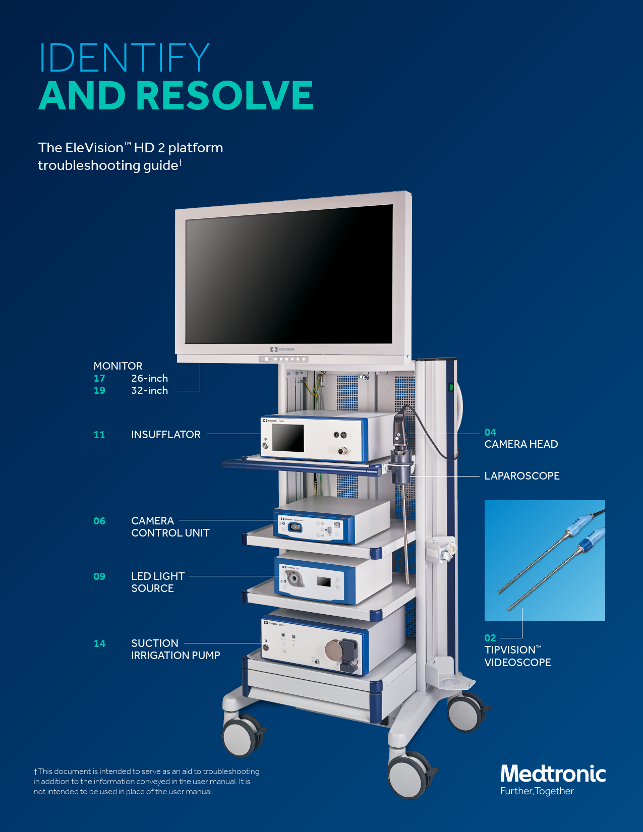
IDENTIFY AND RESOLVE
The EleVisionTM HD 2 platform troubleshooting guide

MONITOR 17 26-inch 19 32-inch
11 INSUFFLATOR
06 CAMERA CONTROL UNIT
09 LED LIGHT SOURCE
14 SUCTION IRRIGATION PUMP
This document is intended to serve as an aid to troubleshooting in addition to the information conveyed in the user manual. It is not intended to be used in place of the user manual.

04 CAMERA HEAD LAPAROSCOPE
02 TIPVISIONTM VIDEOSCOPE

TIPVISIONTM VIDEOSCOPE
What's your issue?
1. Image dark -- insufficient illumination 2. No image 3. Noisy image, black bars, image shift 4. Unnatural colors 5. Appearance of endoscope warnings 6. Appearance of temperature and camera
warnings 7. Corrosion, staining, and discoloration

ERROR & WARNING MESSAGES
Dark image -- insufficient illumination The potential cause Stubborn residue on the glass surfaces can impede proper lighting.
The solution Make sure you clean the glass surfaces to let the proper amount of light through.
No image The potential cause Either the connection cable isn't connected or it could be defective. Another reason the image is missing could be live image failure during operation of a defibrillator.
The solution To solve for this issue you can connect the videoscope to the controller. Make sure you check the plug for moisture. If the cable is defective, send videoscope in for repair. Alternatively, restart the camera control unit. If there is still no live image displayed, send it in for repair.
Noisy image, black bars, or the image shift The potential cause Electromagnetic interference could result in any of the above.
The solution Be sure to remove all potential sources of interference.
Unnatural colors The potential cause The white balance value may not correspond to default anymore.
The solution To ensure the colors are natural, perform a white balance test or simply reset the device.
Appearance of endoscope warnings The potential cause The endoscope tip overheated. Temperature may have risen above 110 degrees Fahrenheit or 43 degrees Celsius.
The solution Switch off device and immerse endoscope tip for about two minutes in a sterile liquid that's approximately 72 degrees Fahrenheit or 22 degrees Celsius. If the warning message doesn't disappear, send it in for repair.

Appearance of temperature and camera warnings
The potential cause The temperature measurement on the distal end is not possible or it has a faulty sensor.
The solution For best results send the videoscope in for repair.
Corrosion, staining, and discoloration
The potential cause The problem can happen due to a number of issues: 1. Inadequate cleaning (e.g. remaining protein residue) 2. Insufficient rinsing between the reprocessing stages,
especially before sterilization 3. Excessive chloride concentration 4. Excessive concentration of minerals (e.g. limescale) or
organic substances 5. Heavy metal ions and/or silicates, elevated concentration
of iron, copper, and manganese in the water or sterilizer steam 6. Contaminated, too frequently reused cleaning and disinfecting solution 7. Extraneous rust, possibly resulting from rust contained in steam or damaged or instruments not corrosion resistant and reprocessed at the same time 8. Contact corrosion
The solution There's a corresponding solution for each cause of this problem: 1. Manual cleaning (reprocessing), rub thoroughly if
necessary, then reprocess 2. Rinse sufficiently between the reprocessing stages 3. Check water quality 4. Check the water quality, only use demineralized water if
necessary 5. Same solution as number four 6. The cleaning and disinfecting solution should be replaced
regularly 7. Check the supply systems. If multiple items are being
reprocessed together, pay attention to material compatibility and signs of prior damage. Try to prevent the different items from touching one another 8. Avoid contact with other devices

3 VIDEOSCOPE

CAMERA HEAD
What's your issue?
1. Dark image -- insufficient illumination 2. No image on the monitor

ERROR & WARNING MESSAGES
Dark image -- insufficient illumination The potential causes 1. The glass surfaces on camera head are soiled. 2. Stubborn residue is on the glass surfaces. 3. The light guide is defective. 4. The camera brightness is set too low. 5. The endoscope optical system is defective. 6. The light output is set too dark. The solution 1. Clean the glass surfaces. 2. Remove residue on the surfaces. 3. Connect a new light guide or if necessary send it in for
repair. 4. Increase the camera's brightness. 5. If the image is too dark even without the camera try a
different endoscope and send in the endoscope for repair. 6. Increase the light output at the light source. No image on the monitor The potential cause The connection cable may not be connected or it's defective. The solution Connect the camera head to the controller and check the plug for moisture. If the cable is defective, send it in for repair.
5 CAMERA HEAD

CAMERA CONTROL UNIT (CCU)
What's your issue?
1. On-screen display does not appear 2. Dark image -- insufficient illumination 3. No image on the monitor 4. Incorrect date and time 5. Light source independently switches on/off 6. Auto light control does not work 7. Camera not connected or incompatibility
message 8. Excess temperature message 9. Light source not connected or
incompatibility message 10. Message: No storage available

11. Message: USB device not compatible with system
12. Message: USB device connected to wrong port
13. Message: No system access to USB storage 14. Transfer incomplete: USB device removal
while saving message 15. Message: while balance failure

ERROR & WARNING MESSAGES
On-screen display does not appear
The potential cause The aspect ratio is set incorrectly.
The solution Correct the position of the on-screen display for the camera.
Dark image -- insufficient illumination
The potential cause 1. The glass surfaces on camera head are soiled. 2. Stubborn residue appears on the glass surfaces. 3. The light guide seems to be defective. 4. Camera brightness set too low. 5. The endoscope optical system seems to be defective. 6. The light output set too dark.
The solution 1. Make sure you clean glass surfaces. 2. Clean the surface to remove any stubborn residue. 3. Connect a new light guide and send it in for repair. 4. Simply increase camera's brightness. 5. If the image is too dark even without the camera, use a
different endoscope and send the defective product in for repair. 6. Increase the light output at the light source.
No image on the monitor
The potential cause 1. There's no power supply. 2. The fuse is likely defective. 3. The controller is incorrectly connected to the monitor. 4. The video cable is defective. 5. The connection cable isn't connected or it's defective. 6. The monitor isn't tuned in to the correct input signal.
The solution 1. Connect and switch on the devices. 2. Replace the fuse. 3. Connect the controller to the monitor correctly. 4. Replace the video cable. 5. Connect the camera head to the controller and check the
plug for moisture. If the cable is defective, send it in for repair. 6. Set the monitor to the correct input signal.
Incorrect date and time
The potential cause Either the date and time aren't set correctly or the battery isn't working.
The solution Set the date and time correctly in the operating menu of the camera or if necessary, change the battery.

Light source independently switches on/off The potential cause It's likely the MIS-Bus fault in the camera or the light source. The solution Disconnect the camera and light source. As well send in camera or light source for repair.
Auto light control does not work The potential cause Light source doesn't support auto light control. The solution Use a compatible light source model.
Camera not connected or incompatibility message The potential cause Camera head not connected to controller or it's not compatible with controller. The solution Connect the compatible camera head to the controller. Or for combination options look at the respective instructions for use of the camera heads.
Excess temperature message The potential cause 1. The controller ventilation slots are covered. 2. The controller fan is defective. The solution 1. Simply uncover the ventilation slots. 2. Send the controller in for repair.
Light source not connected or incompatibility message The potential cause The light source isn't compatible with the controller. The solution Connect the compatible light source to the controller using a MIS-Bus cable.
Message: no storage available The potential cause No USB storage device is connected to the controller. The solution Connect the USB storage device to the front side of the device.
Message: USB device not compatible with system The potential cause The USB storage device has an incompatible file system. The solution Format the USB storage device using the FAT32 file system.

7 CAMERA CONTROL UNIT (CCU)

Message: USB device connected to wrong port The potential cause The USB device is inserted on the rear of the device. The solution Insert the USB device on the front side of the controller. Message: no system access to USB storage The potential cause The USB device is defective. The solution Simply replace the USB device. Transfer incomplete: USB device removal while saving message The potential cause The USB device was removed while saving. The solution Try again and remove the USB device only after saving has concluded. Message: while balance failure The potential cause The white balance test wasn't performed as described in the instructions for use. The solution Repeat the white balance test.
8 CAMERA CONTROL UNIT (CCU)

LED LIGHT SOURCE
What's your issue?
1. Light source does not turn on 2. The light source has no light 3. The light guide cannot be coupled 4. There's not enough light 5. The fans don't work 6. The light source cannot be remotely controlled 7. Auto light control isn't possible 8. The light doesn't switch off -- despite light
guide removal

ERROR & WARNING MESSAGES
Light source does not turn on The potential cause 1. There's no power supply. 2. The power supply unit is malfunctioning. The solution 1. Check the power connection and the fuse. If necessary,
connect the power and/or replace fuse. 2. Send the light source in for repair.
The light source has no light The potential cause The device is overheated. The solution Allow device to cool down.
The light guide cannot be coupled The potential cause The adapter on light guide connection is missing. The solution Screw on the adapter.
There's not enough light The potential cause 1. The light guide isn't connected correctly. 2. The light guide is defective. 3. The adapter isn't screwed on correctly. 4. The light guide isn't completely inserted. The solution 1. Check that the light guide is seated properly and correct it
if necessary. 2. Replace the light guide. 3. Fully screw on adapter. 4. Use a compatible light guide.
The fans don't work The potential cause There's malfunction in fans. The solution Send the light source in for repair.

The light source cannot be remotely controlled The potential cause The MIS-Bus cable isn't properly plugged in or it's defective. The solution Check the connection or replace the cable.
Auto light control isn't possible The potential cause The camera doesn't support auto light control. The solution Use a compatible camera model
Light doesn't switch off -- despite light guide removal The potential cause 1. The light guide wasn't locked. 2. The light guide isn't compatible. The solution 1. Rotate the multilight guide adapter. 2. Use a compatible light guide.

10 LED LIGHT SOURCE

INSUFFLATOR 50L
What's your issue?
1. Low gas supply 2. Change gas bottle 3. Overpressure 4. Venting system active 5. Overpressure/venting system active 6. Occlusion 7. Contamination 8. Contamination/service 9. Gas heater defective 10. Gas temperature >42 degrees Celsius 11. Device terminates -- gas heating/ insufflation 12. Error message for all service 13. Device temperature error 14. Insufflation stopped -- cannot start 15. Venting valve defective

ERROR & WARNING MESSAGES
Low gas supply
The potential causes 1. During device check, the existing gas supply pressure is
too low. 2. During surgery, the gas supply pressure has dropped
below 15 bar. 3. There's insufficient house gas supply.
The solution Open gas bottle or 1. Replace the gas bottle. 2. Check the house gas supply.
Detach the insufflation tube. 1. Close gas supply valve. 2. Replace gas supply. 3. Open gas supply valve. 4. Connect insufflation tube. 5. Continue insufflation.
Check the house gas supply. 1. Open or remove pressure reduction valve if in line with gas
bottle. 2. Check if appropriate house gas connector is used.
Change the gas bottle
The potential cause The gas supply pressure has dropped below 30 bar.
The solution Prepare for changing.

Venting system active
The potential cause The actual pressure is at least mmHg 2�5 and 2�5 seconds above the nominal pressure.
The solution Determine the cause for exceeding the nominal pressure. Check the electronic controls of the device if overpressure exists for a longer period of time.
Overpressure/venting system active
The potential cause The pressure monitor shows that the actual pressure is 2�5 mmHg for 2�5 seconds above the nominal pressure. The overpressure was not reduced within 5 seconds by the venting system.
The solution Determine the cause for exceeding the nominal pressure. Check the electronic controls of the device if overpressure exists for a longer period of time. Reduce the nominal pressure. Check if the instrument's stopcock is open or the tube is plugged up.
Occlusion
The potential cause 1. The tube or instrument occlusion. 2. Faulty Veress needle insertion. 3. The stopcock is closed.
The solution 1. Localize the cause and open/eliminate the occlusion. 2. Check that the Veress cannula is positioned correctly in
the abdomen and make sure the instrument's stopcock is open

Overpressure
The potential cause 1. The pressure monitor shows that the actual pressure is at
least 4 mmHg above the nominal pressure. 2. The actual pressure has reached 30 mmHg/20 mmHg
(depending on the mode).
The solution 1. Determine the cause for exceeding the nominal pressure.
Check the electronic controls of the device if overpressure exists for a longer period of time. 2. Reduce the nominal pressure and determine the cause of exceeding the nominal pressure if necessary.

Contamination
The potential cause Fluid has penetrated the device through the patient gas outlet.
The solution The message is repeated with each start/stop. It's possible to continue using the device with this error message until the device is turned off with the on/ off key.
Contamination/service
The potential cause The device is contaminated with fluid.
The solution The device must be checked by an authorized service technician or clearly marked with a label referring to the contamination and then twice enclosed in a safety foil, sealed, and returned to the manufacturer for repairs.

12 INSUFFLATOR 50L

Gas heater defective
The potential cause Gas heater malfunction.
The solution Check gas heating with a new tube. If this error message is displayed again, have the gas heating checked by a qualified service technician. It is possible to continue using the device without gas heating.
Gas temperature >42 degrees Celsius (107 degrees Fahrenheit)
The potential cause The temperature of the gas exceeds 42 degrees Celsius.
The solutions  Unplug the insufflation tube at the trocar.  Press the start/stop function field. The device insufflates
without heating the gas.  Let hot gas escape until the tube is only warm to the
touch.
Error message
The potential cause The device doesn't work properly and the internal safety system has been triggered.
The solutions  Switch the device off and back on after approx. Three
seconds have expired using the on/off key.  The device is defective if the error message is displayed
again. Make sure the device can no longer be operated until a qualified service technician conducts the appropriate tests and repairs.
Device temperature error
The potential cause 1. The device temperature is above 70 degrees Celsius. 2. The device temperature is below 10 degrees Celsius.
The solution 1. Use the key to turn the device off and allow it to cool off for
about 10 minutes. Make sure the device is not set up in the vicinity of heat sources. 2. Turn the device off for about 10 minutes using the on/off key.
Venting valve defective
The potential cause Venting system malfunctioning
The solution Use the on/off key to turn the device off and turn the device back on after approximately three seconds. If this error message is displayed again after the device check has concluded, have the device checked by an authorized service technician. You can still operate the device without venting system. The error message is repeated with each start/stop.
13 INSUFFLATOR 50L

SUCTION IRRIGATION PUMP
What's your issue?
Device error 1. All LEDs flash rapidly
Short warning beeps, continuously repeated 2. Suction does not start, suction status LED
flashes slowly or short warning beeps repeated three times
Tube warning 1. Irrigation cannot be started
Red tube status LEDs lights -- eight seconds Warning beeps, one short beeps 2. Irrigation cannot be started Red and green tube status LEDs flash slowly Irrigation and suction status LEDs light up Warning beeps, three short beeps 3. Red tube status LED lights up after inserting the tube Warning beeps, three short beeps

4. Red LED flashes slowly after pressing the start key while a tube is inserted Warning beeps, three short beeps irrigation cannot be started
5. Roller wheel stops Red and green tube status LEDs light up Warning beeps, three short beeps
6. Green tube status LED is flashing Warning beep, one short
7. After pressing the start key: Red and green tube status LEDs flash slowly
8. Warning beep, one short
Device information 1. Green tube status LED lights up 2. All LEDs light up briefly -- then go out 3. Warning beep, one long 4. Suction does not automatically shut off
when instrument is closed

ERROR & WARNING MESSAGES
All LEDs flash rapidly and short warning beeps continuously repeated
The potential cause Electronics defective
The solution Turn the device off and back on after approx. 10 seconds. If the error message is displayed again, the device may not be used any longer. Make sure the device can no longer be operated until a qualified service technician conducts the appropriate tests and repairs.
All LEDs flash rapidly and short four warning beeps are continuously repeated
The potential cause Sensor errors: Impermissible deviation or error in the electronics components measuring the pressure. Pressure on sensor while no tube is inserted.
The solution Turn the device off and back on after approximately 10 seconds. If the error message is displayed again, the device may not be used any longer. Make sure the device can no longer be operated until a qualified service technician conducts the appropriate tests and repairs.
All LEDs flash rapidly and short five warning beeps are continuously repeated
The potential cause Motor error: Defective motor control. The motor error warning can also occur during the operation of the device due to a jammed roller wheel.
The solution Turn the device off and back on after approx. 10 seconds. If the error message is displayed again, the device may not be used any longer. Make sure the device can no longer be operated until a qualified service technician conducts the appropriate tests and repairs.
All LEDs flash rapidly and short seven warning beeps are continuously repeated
The potential cause RFID error: Errors in the transponder electronics
The solution Turn the device off and back on after approximately 10 seconds. If the error message is displayed again, the device may not be used any longer. Make sure the device can no longer be operated until a qualified service technician conducts the appropriate tests and repairs.

All LEDs flash rapidly and short 10x warning beeps are continuously repeated
The potential cause Calibration error: The device is not calibrated properly.
The solution Turn the device off and back on after approximately 10 seconds. If the error message is displayed again, the device may not be used any longer. Make sure the device can no longer be operated until a qualified service technician conducts the appropriate tests and repairs.
 Suction does not start  Suction status LED flashes slowly  Short three warning beeps repeated three
times
The potential cause Vacuum pump defective
The solution Turn the device off and back on after approximately 10 seconds. If the error message is displayed again, the device can be used without the integrated vacuum pump. In this case, use external suction. After the surgical procedure, have the device checked by an authorized service technician
TUBE WARNING
 Irrigation cannot be started  The red tube status LEDs lights for eight seconds  Warning beeps, one short beep The potential cause An expired tube was inserted.
The solution Remove tube and insert a new tube. Then, start the irrigation.
 Irrigation cannot be started  Red and green tube status LEDs flash slowly  Irrigation and suction status LEDs light up  Warning beeps, three short beeps The potential cause The pump was switched on while a tube was inserted.
The solution Remove the tube. You can reinsert it after a successful device test. The tube may not be inserted while starting.

15 SUCTION IRRIGATION PUMP

 The red tube status LED lights up after inserting the tube
 Warning beeps, three short beeps
The potential cause The tube has no remaining uses left or it isn't approved for this pump.
The solution Reinsert the tube. If it cannot be detected again, remove the tube, and insert a new one into the pump.
 The red LED flashes slowly after pressing the start key while a tube is inserted
 Warning beeps, three short beeps  Irrigation cannot be started
The potential cause The tube has no remaining uses left or it's not approved for this pump. Also, the start key may have been pressed.
The solution Reinsert the tube. If it's not detected again, remove the tube, and insert a new one into the pump.
 Roller wheel stops  Red and green tube status LEDs light up  Warning beeps, three short beeps
The potential The tube was detected by the transponder but the roller tube is not correctly tensioned over the roller wheel. Then the pump was started.
The solution Remove tube and reinsert. Check the correct fit of the tube on the left side of the roller wheel. The roller wheel must be tensioned across the roller wheel.

 After pressing the start key: Red and green tube status LEDs flash slowly
 One short warning beep
The potential cause The pump was started without an inserted tube or the tube was not detected by the pump, (e.g. defective transponder).
The solution Insert a new tube into pump before starting.
Green tube status LED lights up
The potential cause The tube is OK and irrigation can begin.
All LEDs light up briefly and then go outwith one long warning beep
The potential causes  If the self-test concluded successfully then the pump is
ready.  Suction does not automatically shut off when instrument is
closed  Leakage in tube system or defective vacuum suction
The solution Check the tube system and suction the container for leaks. If there is no leakage, the suction is defective and must be switched off. It's possible to continue using the device without an integrated vacuum pump. In this case, use external suction. After the surgical procedure, have the device checked by an authorized service technician.

Green tube status LED is flashing one short warning beep
The potential cause Last cycle for reusable tube After the surgical procedure is finished, the inserted tube cannot be used any longer.
The solution Make sure a new tube is available for the subsequent surgical procedure.

16 SUCTION IRRIGATION PUMP

26" MONITOR
What's your issue?
1. Power indicator off 2. Power indicator in orange 3. Blurred image, screen interference fringe, or
color edging 4. Abnormal screen image 5. Complete or local broken screen 6. Partial display or broken edges

ERROR & WARNING MESSAGES
Power indicator off The solutions 1. Check the power socket to make sure it's tight. 2. Check the power adapter to make sure it's normal. 3. Ensure the adapter parameters meet the product
requirements. 4. Pull off and insert the power port to restart the monitor. 5. Check the power key is switched to "I" side.
Power indicator in orange The solutions 1. Check the signal line to make sure it's connected properly. 2. Ensure the output resolution of the connected signal
source is the optimum resolution required by the product. 3. Press and hold the lock key to unlock and use the input
1/input 2 key to select interface of the connected signal source. 4. Restart the PC or the connected signal source equipment.
Blurred image, screen interference fringe, or color edging The solutions 1. Check the connecting cable for reliability. 2. We suggest using the accompanied connecting cable. 3. Restart the PC or the connected signal source equipment.
Abnormal screen image The solutions 1. Make sure the output of the current signal source is power. 2. Restart the PC or the connected signal source equipment.
Complete or local broken screen The solutions 1. Please check the format of signal output, as a similar
phenomenon may occur when the output signal of the signal source doesn't match the product. 2. Restart the PC or the connected signal source equipment
Partial display or broken edges The solution Please check the format of the signal output as a similar event can happen when the output signal of the signal source doesn't match the product.
18 26" MONITOR

32" MONITOR
What's your issue?
1. No image on the monitor screen 2. Improper images on the monitor screen 3. Images are too dark 4. Highlighted images are not accentuated 5. Images are too weak 6. Colors are not as specified 7. Wrong screen size 8. Images dislocated 9. Images distorted 10. Inoperative control keys

ERROR & WARNING MESSAGES
No image on the monitor screen
The solutions  Check to see if the AC power cord is tightly plugged in.  Make sure the unit's power switch is turned on.  Check the input signal.  Make sure the input is selected as specified.  Check to see if the signal is listed in the applicable signals
chart.
Improper images on the monitor screen
The solutions  Ensure the input is fed into the selected input terminal.  Check the video signal cable to make sure it's tightly
connected.  Make sure the signal is listed in the applicable signals chart.  Check to see if the signal is fed to the input side, not to the
output side.
Images are too dark
The solutions  Ensure the video signal level is as specified.  Check the brightness control to make sure it's at
minimum.  Make sure the contrast control is at minimum.  Check to see if the backlight level on the user setting
screen is too low.  Check the R. gain, G. gain or B. gain level on the color
setting screen or the RGB gain level to see if it's too low with RGB or components inputs.
Highlighted images are not accentuated
The solutions  Ensure the input signal is connected to the IN side, not to
the OUT side.  Make sure the contrast control is at maximum with high-
level input signals.  Check to see if the S-Video input is handled in the
through-out configuration and if two or more units are connected with the main power off. The S-Video input is terminated off when the main power is turned off. Turn on the main power of all the monitors.

Colors are not as specified with composite video or Y/C signal inputs
The solutions  Make sure the brightness and contrast levels are as
specified.  Check to see if the chroma and hue levels on the image
setting screen are as specified.  Ensure the color temperature is selected and preset as
specified.  Check to see if the R. gain, G. gain or B. gain level on the
color setting screen or the RGB gain level is as specified.
Wrong screen size
The solutions  Check to see if the signal is listed in the applicable signals
chart.  On the display control setting screen, readjust the H.
position, V. position, V. size and clock settings.
Images are dislocated
The solutions  Check to see if the signal is listed in the applicable signals
chart.  On the display control setting screen, readjust the H.
position and clock settings.
Images are distorted
The solutions  Check to see if the external sync signal is connected with
the input signal.  Look at the display control setting screen to see if the
clock setting is as specified.
Inoperative control keys
The solution Check to see if the front key lock function is enabled on the user service setting screen. Hold down the exit front key and turn on the power, and the control keys are unlocked.
If any of the above troubles still exists, call up the memory screen and execute the factory reset. It should be noted, however, that all the user settings are deleted.

Images are too weak
The solutions  Make sure the chroma level is appropriately around 128
with composite video or Y/C input signals.  Check the brightness level to see if it's too high.  Ensure the gamma level is appropriately at 2.2.  Check to see if the R. gain, G. gain or B. gain level on the
color setting screen is too low with RGB or component inputs.

20 32" MONITOR

Contact your local Medtronic sales representative for more information about the EleVisionTM HD 2 platform. medtronic.com/visualizationsolutions
Always refer to the instructions for use included with the product for complete indications, contraindications, warnings, and precautions.
� 2020 Medtronic. All rights reserved. Medtronic, Medtronic logo and Further, Together are trademarks of Medtronic. All other brands are trademarks of a Medtronic company. 07/2020� US-NI-2000009 �[WF#3937293]