Kramer VM-3DT 1:3 HDBT Distributor
This Quick Start Guide provides essential information for installing and operating the Kramer VM-3DT 1:3 HDBT Distributor.
For the latest user manual and firmware updates, visit: www.kramerav.com/downloads/VM-3DT
Step 1: Check what's in the box
- ✔️ VM-3DT 1:3 HDBT Distributor
- ✔️ 1 Power adapter and cord
- ✔️ 1 Quick start guide
- ✔️ 4 Rubber feet
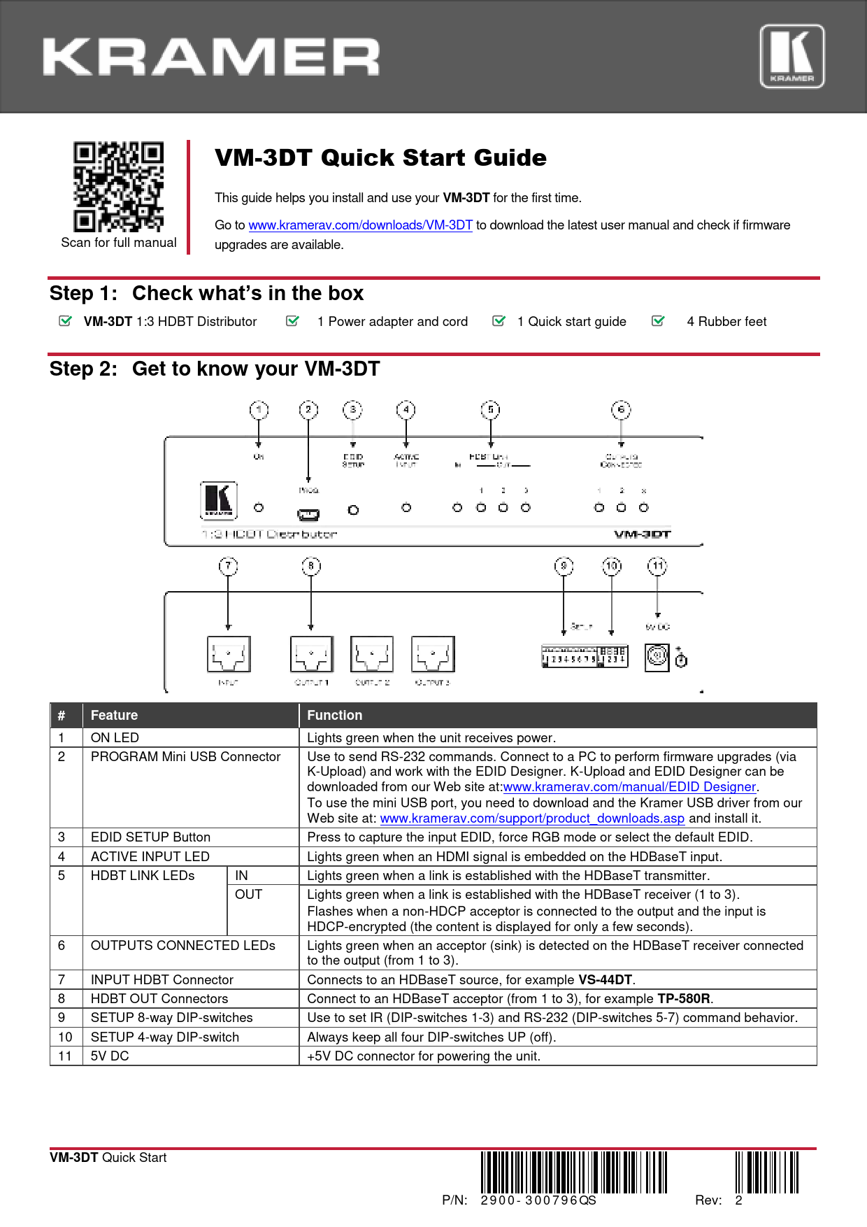
Step 2: Get to know your VM-3DT
The VM-3DT features a compact desktop design with front panel controls and rear panel connectors.
Front Panel Description
The front panel includes the following:
- LED Indicators: ON LED (lights green when powered), ACTIVE INPUT LED (lights green when HDMI signal is on HDBaseT input), HDBT LINK LEDs (IN/OUT, lights green when a link is established), OUTPUTS CONNECTED LEDs (lights green when an acceptor is detected on HDBaseT receiver).
- Buttons: EDID SETUP button (for capturing, forcing RGB, or selecting default EDID).
- Connectors: PROGRAM Mini USB Connector (for RS-232 commands, firmware upgrades via K-Upload, and EDID Designer), 5V DC connector.
- DIP-Switches: 8-way DIP-switches for IR and RS-232 command behavior, and a 4-way DIP-switch (always keep UP/off).
Features Table
| # | Feature | Function |
|---|---|---|
| 1 | ON LED | Lights green when the unit receives power. |
| 2 | PROGRAM Mini USB Connector | Use to send RS-232 commands. Connect to a PC to perform firmware upgrades (via K-Upload) and work with the EDID Designer. K-Upload and EDID Designer can be downloaded from our Web site at: www.kramerav.com/manual/EDID Designer. To use the mini USB port, you need to download and install the Kramer USB driver from our Web site at: www.kramerav.com/support/product_downloads.asp. |
| 3 | EDID SETUP Button | Press to capture the input EDID, force RGB mode or select the default EDID. |
| 4 | ACTIVE INPUT LED | Lights green when an HDMI signal is embedded on the HDBaseT input. |
| 5 | HDBT LINK LEDs (IN/OUT) | IN: Lights green when a link is established with the HDBaseT transmitter. OUT: Lights green when a link is established with the HDBaseT receiver (1 to 3). |
| 6 | OUTPUTS CONNECTED LEDs | Flashes when a non-HDCP acceptor is connected to the output and the input is HDCP-encrypted (the content is displayed for only a few seconds). Lights green when an acceptor (sink) is detected on the HDBaseT receiver connected to the output (from 1 to 3). |
| 7 | INPUT HDBT Connector | Connects to an HDBaseT source, for example VS-44DT. |
| 8 | HDBT OUT Connectors | Connect to an HDBaseT acceptor (from 1 to 3), for example TP-580R. |
| 9 | SETUP 8-way DIP-switches | Use to set IR (DIP-switches 1-3) and RS-232 (DIP-switches 5-7) command behavior. |
| 10 | SETUP 4-way DIP-switch | Always keep all four DIP-switches UP (off). |
| 11 | 5V DC | +5V DC connector for powering the unit. |
Step 3: Install the VM-3DT
Install the VM-3DT using one of the following methods:
- Attach the rubber feet and place the unit on a flat surface.
- Fasten a bracket (included) on each side of the unit and attach it to a flat surface. For more information, visit: www.kramerav.com/downloads/VM-3DT.
- Mount the unit in a rack using the recommended rack adapter (see www.kramerav.com/product/VM-3DT).
Product Image Description: The VM-3DT is a compact, black rectangular device with front and rear panel connections. The front panel features various LEDs, buttons, and a USB port. The rear panel has input and output connectors, DIP switches, and a power input.
Step 4: Connect the inputs and outputs
Always switch OFF the power on each device before connecting it to your VM-3DT. For best results, use Kramer high-performance cables.
HDBT RJ-45 Pinout
Use a straight pin-to-pin cable with RJ-45 connectors. For HDBT cables, it is recommended that the ground shielding be connected/soldered to the connector shield.
T568B Wiring Standard
| PIN | EIA/TIA 568B Wire Color |
|---|---|
| 1 | Orange / White |
| 2 | Orange |
| 3 | Green / White |
| 4 | Blue |
| 5 | Blue / White |
| 6 | Green |
| 7 | Brown / White |
DIP-Switch Setup
To enable/disable IR and RS-232 routing, set the DIP-switches as follows:
DIP-Switch Configuration
| Out # | IR Routing is enabled when: | RS-232 Routing is enabled when: |
|---|---|---|
| OUT 1 | DIP 1 – OFF (up) | DIP 5 - OFF (up) |
| OUT 2 | DIP 2 – OFF (up) | DIP 6 - OFF (up) |
| OUT 3 | DIP 3 – OFF (up) | DIP 7 - OFF (up) |
Note: DIP-switches 4 and 8 are reserved for future use. By default, all DIP-switches are set to OFF (up).
For optimum range and performance, use recommended Kramer cables available at: www.kramerav.com/product/VM-3DT.
Step 5: Connect the power
Connect the power adapter to the VM-3DT and plug the adapter into the mains electricity.
Safety Instructions
- Caution: There are no operator serviceable parts inside the unit.
- Warning: Use only the Kramer Electronics power supply that is provided with the unit.
- Warning: Disconnect the power and unplug the unit from the wall before installing.
- See www.KramerAV.com for updated safety information.
Step 6: Operate the VM-3DT
Acquire EDID
EDID can be acquired using the following methods:
- Using the EDID SETUP front panel button.
- Using the Kramer EDID Designer PC tool connected to USB.
- Manually sending RS-232 serial commands via laptop connected to USB.
USB Setup for RS-232 Communication
| Parameter | Value |
|---|---|
| RS-232 | |
| Baud Rate | 115200 |
| Data Bits | 8 |
| Stop Bits | 1 |
| Parity | None |
| Command Format | ASCII |
| Example (Copy EDID from Output 1 to Input) | "#CPEDID 1,1,0<cr>" |
Factory Reset
Protocol 3000: "#FACTORY" command to reset to factory default configuration.
Note: The VM-3DT supports Kramer EDID Designer, available via the mini USB port. Download it from the Kramer Web site: Kramer EDID Designer.
To use the mini USB port, download and install the Kramer USB driver from: www.kramerav.com/support/product_downloads.asp.
Acquiring the EDID via Front Panel
Press the EDID SETUP button once to display the current EDID source (OUT 1, OUT 2, OUT 3, or all OUT LEDs flash for default EDID).
To acquire an EDID:
- Press EDID SETUP. The current EDID source is displayed.
- Press EDID SETUP again to enter EDID select mode.
- Press EDID SETUP repeatedly to cycle through EDID source options. The OUT LEDs flash in sequence: OUT 1 ➡️ OUT 2 ➡️ OUT 3 ➡️ all output LEDs flash (default EDID). Stop when the desired source is reached.
- Wait a few seconds for the VM-3DT to acquire the EDID. All output LEDs return to normal operation, showing connection status.
If an unconnected output is chosen or the EDID cannot be read, the VM-3DT loads the default EDID.
Forcing the RGB Mode
Normally, the device supports any color space defined in the acquired EDID. If color space issues occur, Force RGB mode may improve image colors.
| Action | Procedure |
|---|---|
| Force acquired EDID to support only RGB color space: | Press and hold the EDID button for a few seconds until all output LEDs flash four times. Continue to acquire the desired EDID. This EDID will be forced to RGB color space only. |
| Return to normal EDID mode: | Press and hold the EDID button for a few seconds until the output LEDs flash once. Continue to acquire the desired EDID. |
| View current EDID mode: | Power cycle the unit. All output LEDs will flash once in normal EDID mode and four times in Force RGB mode. |
Technical Specifications
| Category | Specification | Details |
|---|---|---|
| Input | 1 HDBT | On a female HDMI connector |
| Outputs | 3 HDBT | On RJ-45 female connectors |
| Ports | 1 USB | On a Mini female connector |
| Maximum Extension Range | 40m (130ft) | At 4K@60Hz (4:2:0) |
| 70m (230ft) | At full HD (1080p@60Hz 36bpp) | |
| Note: The specs apply only when using Kramer HDBaseT cables. Reach applies to each IN and OUT port separately; total end-to-end reach is the sum of all ports' reach. | ||
| Video | Max. Resolution | 4K@60Hz 4:2:0 |
| Max. Data Rate | 10.2Gbps (3.4Gbps per graphic channel) | |
| Compliance | Supports HDMI 2.0, HDCP 1.4 and HDBaseT 1.0 | |
| Control | Front Panel | EDID SETUP button, OUTPUTS CONNECTED, HDBT LINK, ACTIVE INPUT, and ON indication LEDs |
| Rear Panel | DIP-switches | |
| Power | Consumption | 5V DC, 3.2A |
| Source | 5V DC, 4A | |
| Environmental Conditions | Operating Temperature | 0° to +40°C (32° to 104°F) |
| Storage Temperature | -40° to +70°C (-40° to 158°F) | |
| Humidity | 10% to 90%, RH non-condensing | |
| Regulatory Compliance | Safety | CE, FCC |
| Environmental | RoHs, WEEE | |
| Enclosure | Size | Desktop |
| Cooling | Fan ventilation | |
| General | Net Dimensions (W, D, H) | 21.5cm x 16.3cm x 4.4cm (8.4" x 6.4" x 1.8") |
| Shipping Dimensions (W, D, H) | 35.1cm x 21.2cm x 7.2cm (13.8" x 8.3" x 2.8") | |
| Net Weight | 0.53kg (1.2lb) approx. | |
| Shipping Weight | 1.3kg (2.9lb) approx. | |
| Accessories | Included | Power cord and adapter |
Specifications are subject to change without notice at www.kramerav.com.
