ℹ️ Document Conversion Notice:
This page was converted from the original file for easier reading. Diagrams/images may appear only in the original PDF below.
File info: application/pdf · 5 pages · 620.56KB
Bosch PRA-ES8P2S Ethernet Switch
8xPoE, 2xSFP
Brand: Bosch
Model: PRA-ES8P2S
Overview
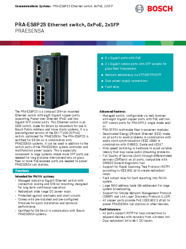
The PRA-ES8P2S is a compact DIN-rail mounted Ethernet switch featuring eight Gigabit copper ports with Power over Ethernet (PoE) and two Gigabit SFP combo ports. This switch is an OEM product made for Bosch by Advantech, specifically for use in Bosch Public Address and Voice Alarm (PA/VA) systems. It is a pre-configured version of the Advantech EKI-7710G-2CPI-AE switch, optimized for the PRAESENSA system. The PRA-ES8P2S is certified for EN 54-16 when used in conjunction with PRAESENSA systems. It serves as an expansion option for PRAESENSA system controllers and multifunction power supplies, particularly useful in large systems requiring additional SFP ports for long-distance fiber optic interconnections or more PoE-enabled ports for powering PRAESENSA call stations.
Functions
Intended for PA/VA systems
Managed industrial Gigabit Ethernet switch with convection cooling and DIN-rail mounting, designed for long-term continuous operation.
Redundant wide-range DC power input.
Protected against overloads and short circuits.
Comes with pre-installed and pre-configured firmware for quick installation and optimum performance.
Certified for EN 54-16 in combination with Bosch PRAESENSA systems.
Advanced Features
Managed switch, configurable via web browser, with eight Gigabit copper ports providing PoE (?) and two SFP combo ports for PRA-SFPLX (single mode) and/or PRA-SFPSX (multimode) fiber transceiver modules.
Energy Efficient Ethernet (EEE) mode is deactivated on all ports to prevent issues with audio clock synchronization (IEEE 1588) in conjunction with OMNEO, Dante, and AES67.
Wire speed switching is implemented in hardware to minimize variable latency that could affect audio streaming.
Full Quality of Service (QoS) is provided through differentiated services (DiffServ) on all ports, compatible with the OMNEO Docent diagnostic tool.
Supports Rapid Spanning Tree Protocol (RSTP) according to IEEE 802.1d for creating redundant network loops.
Includes a fault output relay for reporting system faults to the PA/VA system.
Features a large MAC address table (8k addresses) suitable for large system broadcasting.
Supports Simple Network Management Protocol (SNMP) and Link Layer Discovery Protocol (LLDP).
All copper ports provide PoE (IEEE 802.3 af/at) to power PRAESENSA call stations or other connected devices.
Fault Tolerance
All ports support RSTP for creating loop connections to adjacent devices, enabling recovery from broken links.
Dual redundant 24 to 48 V DC inputs (⚡) provide power resilience.
Diagrams and Indicators
Diagram: Visual representation of the switch's front ports. It shows 8 RJ45 ports labeled 1-8, each indicated with a PoE symbol (?). Ports 9 and 10 are labeled SFP combo ports. Key features are listed: 8 x Gigabit ports with PoE (?), 2 x Gigabit combo ports with SFP sockets for glass fiber transceivers, Network redundancy via STP/MSTP/RSTP, Dual power supply connections (⚡), Fault relay (⚠️).
Connection and Functional Diagram: Block diagram illustrating the switch's architecture. Ports 1 through 8 are shown as RJ45 with PoE (?) connections. Ports 9 and 10 are shown as SFP combo ports. Power inputs PWR1 and PWR2 (⚡) are depicted, along with a Fault relay output (⚠️) labeled P-Fail, and a Console port. A legend identifies symbols for Power over Ethernet power source (?), Controller, SFP Socket for SFP module ([SFP]), DC to DC converter, Fault relay (⚠️), and OMNEO network switch.
Front View: Illustration of the switch's front panel, displaying the 8 RJ45 ports and 2 SFP ports. Status LEDs are visible for each port indicating Link activity, network speed (100 Mbps/1Gbps), and PoE activation. System status (SYS), Ring Master (R.M.), and power supply status (PWR1) indicators are also shown.
Rear View: Illustration of the switch's rear panel, showing the dual DC power input connectors (PWR1, PWR2) and the Console port.
Top View: Illustration of the switch's top panel, showing the chassis ground connection and the dual DC power input connectors (PWR1, PWR2).
Front Panel Control
Reset: System soft reset or factory reset.
Front Panel Connections
Port 1-8: Network port 1-8 with PoE (?).
Port 9-10: Network combo port 9-10 (RJ45/SFP).
Console: Console serial RS232 cable COM port.
Front Panel Indicators
Port / Indicator
Description
Color
Port 1-10 ∧
Link activity
Green
Port 1-10 v
100 Mbps network
Yellow
Port 1-10 v
1Gbps network
Green
PoE 1-8
PoE activated (?)
Green
SYS
System is operating normally
Green
R.M.
Active when determining ring master
Green
PWR1
Power on power supply input 1 (⚡)
Green
Top Panel Connections
Chassis ground
PWR1: 24 to 48 VDC input 1 (⚡)
PWR2: 24 to 48 VDC input 2 (⚡)
P-Fail: Fault relay (⚠️)
Architects' and Engineers' Specifications
The Ethernet switch shall be a managed 10-port Gigabit switch with eight ports providing PoE (?) and two ports providing SFP sockets ([SFP]) for glass fiber transceivers. The switch shall have dual redundant, wide-range DC power supply inputs for 24 to 48 V (⚡). It shall supervise its DC power supply inputs and port links, and have a fault relay output (⚠️) for fault reporting.
Certifications and Approvals
Emergency standard certifications
Region
Standard
Europe
EN 54-16
International
ISO 7240-16
Maritime applications
DNV GL Type Approval
Emergency standard compliance
Region
Standard
Europe
EN 50849
UK
BS 5839-8
Regulatory areas
Area
Standard
Safety
UL 508
Immunity
EN 55024, EN 61000-4-2, EN 61000-4-3, EN 61000-4-4, EN 61000-4-5, EN 61000-4-6, EN 61000-4-8
Emissions
EN 55032 class A, EN 61000-6-4, FCC-47 part 15B class A
Environment
EN 50581
Shock
IEC 60068-2-27
Freefall
IEC 60068-2-32
Vibration
IEC 60068-2-6
Conformity declarations
Region
Declaration
Europe
CE/CPR
USA/Canada
FCC/c-UL
Korea
KE
Parts Included
Quantity
Component
1
10-port industrial Ethernet switch
1
Screw connector
2
Wall-mounting bracket
1
DIN-rail mounting bracket and screws
1
Startup manual
Technical Specifications
Quick overview
Specification
Value
Operating voltage (VDC)
16.8 - 62.4 VDC
Power consumption (W)
140 W maximum
PoE/PoE + power budget
120 W maximum
PoE/PoE + power per port
20 W maximum
PoE/PoE + standard
IEEE 802.3 af/at
Switch type
Managed
Number of RJ45 ports
10
Number of RJ45 interfaces with PoE (?)
8
Number of SFP ports
2
MAC table size
8k
Fault output (⚠️)
Relay
Additional features
Pre-configured for PRAESENSA
Ethernet type
100BASE-TX; 1000BASE-T
Cooling
Convection
Mounting type
Rail-mounted; Wall-mounted
Protection
Watchdog; RSTP; Rate limiting; Storm control
Degree of protection (IEC 60529)
IP30
Operating temperature (°C)
-40 - 75 °C
Dimension (H x W x D) (mm)
152 x 74 x 105 mm
Electrical
Power transfer
Specification
Value
Power supply input PWR1-2 (⚡)
24 to 48 VDC
Input voltage tolerance
16.8 to 62.4 VDC
Power consumption (48 V)
12 W (Active mode, no PoE) < 140 W (Active mode, with PoE ?)