GS34P02Q13-01E
File info: application/pdf · 24 pages · 999.50KB
GS34P02Q13-01E
25th Edition: Feb. 22, 2021
General FCN-RTU Low Power 6SHFL¿FDWLRQV Autonomous ...
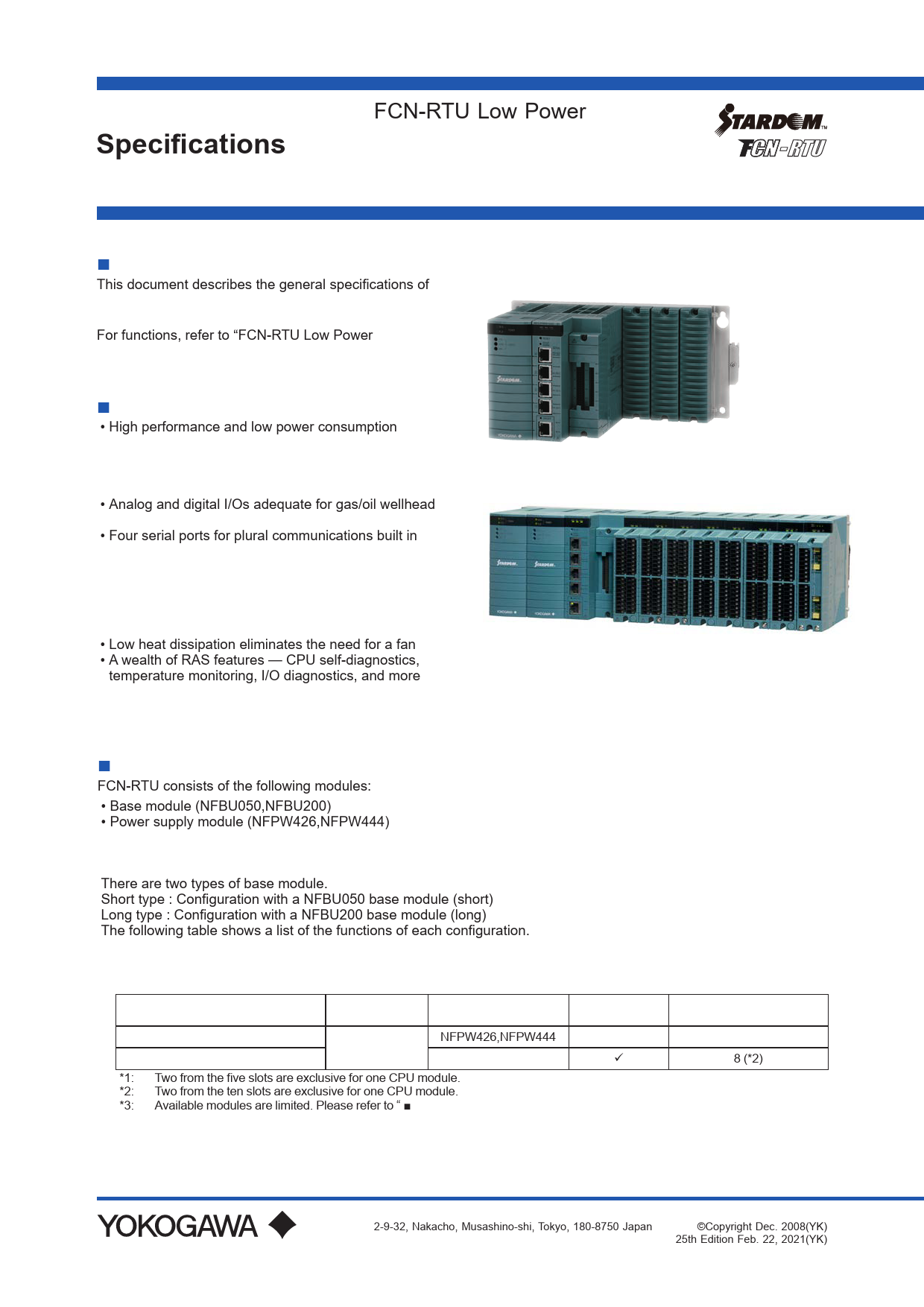
25th Edition Feb. 22, 2021(YK) F01E.ai CONFIGURATION. FCN-RTU consists of the following modules: • Base module (NFBU050,NFBU200) • Power supply module (NFPW426,NFPW444) • CPU (with built-in I/Os) module (NFCP050) • Addi…
General Specifications: FCN-RTU Low Power ... - Yokogawa
22, 2021(YK). F01E.ai ... When FCN-RTU is used under the ATEX Type "n" environment, the Instruction Manual, "Explosion Protection of FCN/FCJ. Products" (IM ...
General FCN-RTU Low Power 6SHFL¿FDWLRQV Autonomous Controller ...
Extracted Text
<<Contents>> <<Index>>
General Specifications
GS 34P02Q13-01E

FCN-RTU Low Power Autonomous Controller
Hardware

 GENERAL
This document describes the general specifications of the FCN-RTU low power autonomous controller with NFCP050 CPU module.
For functions, refer to "FCN-RTU Low Power Autonomous Controller Functions" (GS 34P02Q0201E).
 FEATURES
� High performance and low power consumption modular controller
� Memory with ECC. � FCN-RTU can be used wide temperature range and
high altitude place. � Analog and digital I/Os adequate for gas/oil wellhead
control built in CPU module � Four serial ports for plural communications built in
CPU module � Up to eight additional I/O modules (with NFBU200) � Wide voltage range (10 to 30 V DC input) power
supply module (NFPW426) � Power supply module can be duplexed (NFBU200
with NFPW444) � Low heat dissipation eliminates the need for a fan � A wealth of RAS features -- CPU self-diagnostics,
temperature monitoring, I/O diagnostics, and more � Additional I/O modules (except CPU embedded I/Os)
hot-swappable

Short type (NFBU050) Long type (NFBU200)

F01E.ai
F01cE.ai

 CONFIGURATION
FCN-RTU consists of the following modules:
� Base module (NFBU050,NFBU200) � Power supply module (NFPW426,NFPW444) � CPU (with built-in I/Os) module (NFCP050) � Additional I/O modules (up to eight modules can be mounted on a base module)
There are two types of base module. Short type : Configuration with a NFBU050 base module (short) Long type : Configuration with a NFBU200 base module (long) The following table shows a list of the functions of each configuration.

Table FCN-RTU Control Function List

Base module

CPU Module Power supply module

NFBU050 base module (short) NFBU200 base module (long)

NFCP050

NFPW426,NFPW444 NFPW444

*1: Two from the five slots are exclusive for one CPU module. *2: Two from the ten slots are exclusive for one CPU module. *3: Available modules are limited. Please refer to "  I / O module".

Power supply Redundancy
N.A.


Max number of mountable I/O modules (*3) 3 (*1)
8 (*2)

Yokogawa Electric Corporation 2-9-32, Nakacho, Musashino-shi, Tokyo, 180-8750 Japan

GS 34P02Q13-01E
�Copyright Dec. 2008(YK) 25th Edition Feb. 22, 2021(YK)

<<Contents>> <<Index>>
 Examples of Configuration Short type (NFBU050)

PWM CPU IOM IOM IOM

Unit:1 Slot 1

2 3 45
F02E.ai

Long type (NFBU200)

2

 POWER CONSUMPTION
Table Power Consumption of FCN-RTU (Minimum Consumption Configurations)

SERIAL+

not used

DI/O+AI/O (built-in

I/Os: DI, DO, AI, AO, PI) used

NETWORK (Ethernet)

not used

used

1.6 W

2.3 W

2.1 W

2.9 W

Note: When FCN-RTU is composed of NFCP050, NFBU050 and NFPW426 (Without additional I/O
modules and analog field power supply for built-in AO).

PWM PWM CPU IOM IOM IOM IOM IOM IOM IOM IOM

Slot 1 2 3 4 5 6 7 8

Abbreviation PWM CPU IOM

Description Power supply module CPU module (with built-in I/Os) Additional I/O module

9 10
F23E.ai

 INSTALLATION REQUIREMENTS

Item Ambient temperature

Specification Operation Transportation/storage

-40 to +70 �C (*1) -40 to +85 �C

Ambient humidity

Operation Transportation/storage

5 to 95 %RH (no condensation) 5 to 95 %RH (no condensation)

Rate of change in temperature
Dust

Operation Transportation/storage

Within �10 �C/h Within �20 �C/h 0.3 mg/m3 or less

Protection class

IP20

Resistance to corrosive gases Resistance to vibration Resistance to shock

ANSI/ISA S71.04 Class G2 (Standard) (ANSI/ISA S71.04 Class G3, option) 0.15mm P-P (5 to 58 Hz) 1 G (58 to 150 Hz) 15 G, 11 ms (during power-off, for sine half-waves in XYZ-directions)

Altitude

3000 m or less (*1)

Electric field

3 V/m or less (26 MHz to 1 GHz)

Noise

Magnetic field

30 A/m (AC) or less, 400 A/m (DC) or less

Grounding Cooling

Electrostatic discharge

4 kV or less contact discharge, 8 kV or less aerial discharge
Apply the grounding system which is defined by the rules and standards of the country or the region.
Natural air cooling

*1: It depends on additional I/O modules. Refer to " I/O MODULES" for details.

All Rights Reserved. Copyright � 2008, Yokogawa Electric Corporation

GS 34P02Q13-01E May 12, 2014-00

<<Contents>> <<Index>>

3

 COMPLIANT STANDARDS

Safety Standards (*1) (*8) (*11)

Item CSA
CE Marking Low Voltage Directive EAC Marking Morocco Compliance Marking (C Marking)
CE Marking EMC Directive RCM

Standards
CAN/CSA-C22.2 No.61010-1 CAN/CSA-IEC 61010-2-201 CAN/CSA-C22.2 No.61010-2-030
EN 61010-1 EN 61010-2-201 EN 61010-2-030
CU TR 004
NM EN 61010 1 NM EN 61010 2 201 NM EN 61010 2 030 NM EN 60825 1 EN 55011 Class A Group 1 (*9) EN 61000-6-2 (*1) (*2) (*3)
EN 55011 Class A Group 1 (*9)

EMC Standards
Standards for Hazardous Location Equipment (*4) (*5)
Restriction of Hazardous Substances (*5)

KC Marking EAC Marking Morocco Compliance Marking (C Marking)
US (FM) Nonincendive (*1)
ATEX Type "n" (*6) (*7)
Canada (CSA) Non-Incendive (*1)
IECEx Type "n" (*1) Emirates Conformity Assessment Scheme (ECAS-Ex) Type "n" (*1) RoHS Directive (*12) UAE RoHS Directive

Korea Electromagnetic Conformity Standard
CU TR 020
NM EN 55011 Class A Group 1 (*7) NM EN 61000 6 2 NM EN 61000 3 2 NM EN 61000 3 3
Class I Division 2, Groups A, B, C, D T4 FM 3600:2018 FM 3611:2018 FM 3810:2018 ANSI/UL 121201:2017 ANSI/UL 61010-1:2012 ANSI/UL 61010-2-30:2012
ANSI/UL 61010-2-201:2014
II 3 G Ex nA nC II C T4 Gc X (*10) EN IEC 60079-0:2018 EN 60079-15:2010
Class I Division 2, Groups A, B, C, D T4 C22.2 No.213-17 CAN/CSA-C22.2 No.61010-1-12 CAN/CSA-C22.2 No.61010-2-030-12 CAN/CSA-IEC 61010-2-201:14
Ex nA IIC T4 Gc IEC 60079-0 Ed. 7.0 (2017) IEC 60079-15:2010
Ex nA IIC T4 Gc IEC 60079-0 Ed. 7.0 (2017) IEC 60079-15:2010
EN IEC 63000:2018
UAE Cabinet Decision No. 10 of 2017

*1: For the rack-mountable devices, DIN rail-mountable devices, and wall-mountable devices to meet the Safety Standards and EMC Standards, the devices must be installed in a lockable metal cabinet. The cabinet must conform to IEC/EN/CSA 61010-2-201 or provide degrees of protection IP3X or above and IK09 or above.
*2: For lightning surge immunity, a device such as a lightning arrester needs to be installed externally. Some module can select a pressure clamp terminal block with surge absorber. For details, refer to "Terminal Block" (GS 34P02Q41-01E).
*3: When using the NFCP050 or NFLP121, mount ferrite cores as shown below in order to meet the EMC standards. � NFCP050 (CPU module): Mount two ferrite cores "A1193MN" to Ethernet cable of the NFCP050 side. � NFLP121 (PROFIBUS-DP Communication module) : Mount one ferrite core "A1193MN" to PROFIBUS-DP cable of the NFLP121 side.
*4: Refer to TI 34P02Q91-01E for the products meeting NI. *5: For modules conforming to each standards, refer to the section "I/O Module" and the table "List of I/O Modules" of this
document.
*6: When FCN-RTU is used under the ATEX Type "n" environment, the Instruction Manual, "Explosion Protection of FCN/FCJ Products" (IM 34P02Q11-02E) is required for safer installation and wiring.
*7: To be compliant with these standards, the FCN-RTU hardware needs to be installed in a lockable metal cabinet of IP54 or higher protection rating.
*8: For ensuring the FCN-RTU hardware to satisfy the safety standards, the dedicated breakers in the power supply side must be installed and conform to the following specifications. � [CSA] CSA C22.2 No.5 or UL 489 � [CE Marking] EN 60947-1 and EN 60947-3

All Rights Reserved. Copyright � 2008, Yokogawa Electric Corporation

GS 34P02Q13-01E Feb. 22, 2021-00

<<Contents>> <<Index>>

4

*9: A Class A hardware device is designed for use in the industrial environment. Please use this device in the industrial environment only.
*10: This marking is the explosion-proof specification for FCN-RTU. The marking of each module is either " II 3G Ex nA II C T4 Gc X" or " II 3G Ex nA nC II C T4 Gc X". Symbol `X' denotes the specific condition of use. See "Explosion Protection of FCN/FCJ Products" (IM 34P02Q11-02E) for detail.
*11: To be compliant with these standards, the FCN's cable which is drawn out from the metal, needs to be used the VW-1 class or more of flame-retardant cable.
*12: Including the confirmation of 10 restricted substances defined in the Commission Delegated Directive(EU) 2015/863 amending Annex II to Directive 2011/65/EU.
In relation to the CE Marking, the manufacturer and the authorised representative for the Product in the EEA are indicated below:
� Manufacturer: Yokogawa Electric Corporation (2-9-32 Nakacho, Musashino-shi, Tokyo 180-8750, Japan)
� Authorised representative in the EEA: Yokogawa Europe B.V. (Euroweg 2, 3825 HD Amersfoort, The Netherlands)
"Administration on the Control of Pollution Caused by Electrical and Electronic Products" in the People's Republic of China.
The Product information required by the law is disclosed in the Yokogawa's website. Please refer to the following site.
http://www.yokogawa.com/dcs/CNRoHS/

This instrument is intended to be sold and used only as a part of equipment which is excluded from EU WEEE (Waste Electrical and Electronic Equipment) Directive, such as large-scale stationary industrial tools, a large-scale fixed installation and so on, and therefore, subjected to the exclusion from the scope of the WEEE Directive.

All Rights Reserved. Copyright � 2008, Yokogawa Electric Corporation

GS 34P02Q13-01E Feb. 22, 2021-00

<<Contents>> <<Index>>

5

 BASE MODULE
A base module is a chassis on which various function modules such as CPU, power supply, and I/O modules are mounted to configure a control unit.

 Model and Suffix Codes Base Module (short)

Model
Suffix Codes

Description

NFBU050 Base module (short)

-S

Standard type

1

DIN rail-mounted

5

Basic type with no explosion protection

6

With ISA Standard G3 option and no explosion protection

E

Basic type with explosion protection

F

With ISA Standard G3 option and explosion ptrotection

Base Module (long)

Model
Suffix Codes

Description

NFBU200 Base module(long)

-S

Standard type

0

19-inch rack-mounted

1

DIN rail-mounted

5

Basic type with no explosion protection

6

With ISA Standard G3 option and no explosion protection

E

Basic type with explosion protection

F

With ISA Standard G3 option and explosion ptrotection

Optional Accessories

Model

NFDCV01 NFDCV02

Description
Dummy cover for I/O module slot
Dummy cover for power supply module slot

 Specifications

Item

Model

NFBU050-S1

Max number of mountable I/O modules

3

Number of mountable Power suply modules 1

Weight

0.58 kg

Dimensions (WHD)

28313124.2 mm

Mounting

DIN rail-mounted

Maximum 5 V Self-consumption power consumption 24 V Self-consumption

0.025 A 0

*1: Only NFPW444 power supply module can be redundant.

Specification NFBU200-S0 8 2 (*1) 1.9 kg 482132.5 40.5 mm 19-inch rack-mounted 0.4 A(max)

NFBU200-S1 8 2 (*1) 1.0 kg 440131 42.3 mm DIN rail-mounted

All Rights Reserved. Copyright � 2008, Yokogawa Electric Corporation

GS 34P02Q13-01E May 22, 2020-00

<<Contents>> <<Index>>  Dimensions DIN rail-mounted Model (NFBU050)
283 273 243.6

66.5

DIN rail-mounted Model (NFBU200)

1.25 18

401.5

444

1.9

440.2

Unit: mm
24.2 20.6 16.1

131 110

10.5

F03E.ai

18

6
Unit: mm 35 7 16

19 inch rack-mounted Model (NFBU200)

21.3

440

482.6

8.45

465.7

F26.ai
Unit: mm
40.5 17.6 18.4

131 37.7 57.1
132.5

All Rights Reserved. Copyright � 2008, Yokogawa Electric Corporation

F25E.ai
GS 34P02Q13-01E May 22, 2020-00

<<Contents>> <<Index>>

7

 POWER SUPPLY MODULE (NFPW426, NFPW444)
NFPW426 power supply module mounted on the base module model NFBU050.
NFPW444 power supply module mounted on the base module model NFBU050 and NFBU200.
These power supply module has output functions (5 V DC power supply, 24 V DC analog field power supply for additional I/O modules).

 Model and Suffix Codes

Model
Suffix Codes

NFPW426 -5 -E
0

Description
Power supply module (12 V DC input, 24 V DC input) (*1) Standard type with no explosion protection
Standard type with explosion protection
Basic type

1

With ISA Standard G3 option

*1: This power supply module can be mounted only on the base module model NFBU050.

Model
Suffix Codes

NFPW444 -5 -E
0 1

Description Power supply module (24 V DC input) Standard type with no explosion protection Standard type with explosion protection
Basic type
With ISA Standard G3 option

Power supply terminals (Model NFPW444)

Pin No. 1 2

Name
FLD 24V DC +
FLD 24V DC -

3 G( )

4+

5-

Signal 24 V DC analog field power supply (+) (*1) 24 V DC analog field power supply (-) (*1) Ground of line filter
Power input

*1: When analog I/O modules such as NFAB841 are installed, an analog field power supply is needed.

Checking terminals

Pin No. Name

Signal

1 +5 V-CHK Checking of 5 V system power

2 +24 V-CHK Checking of 24 V field power supply

3 GND

Signal grounding

 LEDs

 Pin Assignment Power supply terminals (Model NFPW426)

Pin No. Name 1+ 23 G( )

Signal
24 V DC analog field power supply enable (+) (*1) (*2)
24 V DC analog field power supply enable (-) (*1) (*2)
Ground of line filter

4+ 5-

Power input

*1: To drive analog field power supply function, supply the same voltage at 24 V DC analog field power supply enable (+) and (-) (connect Pin No.
5 to Pin No. 2, and connect Pin No. 4 to Pin No. 1).
*2: When analog I/O modules such as NFAB841 are installed, an analog field power supply is needed.

LED Indicator Color SYS-POWER Green FLD-POWER Green

Description
Lights when the 5 V system power output is on.
Lights when the 24 V field power supply is on.

 Dimensions
Unit: mm

146.5

49.7

133

13.5

130

F04E.ai

All Rights Reserved. Copyright � 2008, Yokogawa Electric Corporation

GS 34P02Q13-01E May 22, 2020-00

<<Contents>> <<Index>>

8

 Specifications

Model

Item

NFPW426

Specification NFPW444

Rated input voltage

12 V DC, 24 V DC

24 V DC

Input

Input voltage range Input current Fuse rating Rush current Withstanding voltage

10 to 30 V DC
Max. 4 A 3.4 A, 12 V DC input 1.7 A, 24 V DC input
6.3 A
Max. 4.3 A for 200 ms, 12 V DC input Max. 9.2 A for 200 ms, 24 V DC input
500 V AC for 1 minute

21.6 to 31.2 V DC Max. 3.3 A 6.3 A Max. 20 A 500 V AC for 1 minute

Power supply

Insulation resistance
Insensitive momentary powerfailure time Rated output voltage

50 M at 500 V DC 2 ms (100%) +5.1 V DC

50 M at 500 V DC 2 ms (90%) +5.1 V DC

Rated output current

0 to 2.4 A

0 to 7.8 A (*1)

Peak current

2.52 A

11.8 A

Total output Output
Startup time after power-on
Overvoltage protection Overcurrent protection Rated input voltage

12 W
Max. 300 ms
Max. 7 V Min. 105% (auto recovery)
-

40 W (60W peak)
Max. 300 ms Max. 100 ms (during a momentary power failure of 200 ms long with the rated input)
Max. 7 V
Min. 105% (Shutdown after 4 to 14 seconds long overcurrent)
24 V DC � 10%

input Input current

-

Max. 4 A

Fuse rating

-

6.3 A

Analog
field power supply

output

Rated output voltage Rated output current Peak current Total output

24 V DC 0 to 0.54 A 0.57 A 13 W

Input voltage minus matching-diode drop 4 A (*2)
-

Startup time after power-on

Max. 300 ms

-

Overvoltage protection

Max. 36 V

Max.35 V

Overcurrent protection Duplex configuration Weight

Min. 105% (auto recovery) Impossible 0.61 kg

-
Possible (when installed on base module NFBU200)
0.6 kg

Dimensions (WHD)

49.7  130  146.5 mm

49.7  130  146.5 mm

*1: When ambient temperature is higher than 55�C, the rated output current is limited to 75% (0 to 5.85 A). *2: When ambient temperature is higher than 55�C, the rated output current is limited to 75% (3 A).

All Rights Reserved. Copyright � 2008, Yokogawa Electric Corporation

GS 34P02Q13-01E May 22, 2020-00

<<Contents>> <<Index>>

9

 CPU MODULE (NFCP050)
One CPU module is mounted in control unit. The CPU module runs a real-time operating system, supports programming languages compliant with the IEC 61131-3 international standard, and serves as a Java virtual machine. Especailly, this CPU module has built-in I/Os and built-in software licenses.
 Model and Suffix Codes

Description

Model NFCP050

CPU module for FCN-RTU

-S

Standard type

1

Extended type (*1)

5 Suffix Codes
6

Basic type with no explosion protection With ISA Standard G3 option and no explosion protection

E

Basic type with explosion protection

F

With ISA Standard G3 option and explosion protection

*1: For details, refer to "FCN-RTU Low Power Autonomous Controller Functions" (GS 34P02Q02-01E).

 Specifications

CPU

Item

Specification

Model

NFCP050-S

CPU

SH-4A (SH7730) 256 MHz

Memory

Main Static RAM

128 MB with ECC 1 MB with ECC, backed up by battery

System

128 MB on-board flash memory

Serial Port (*1) Communication method Synchronization

3 RS-232 ports (SERIAL: 1, 2, 3), non-isolated, RJ45 modular jacks 1 RS-422/RS-485 port (SERIAL: 4), non-isolated, RJ45 modular jack
RS-232: Full/Half duplex (software settings) RS-422/RS-485: Full/Half duplex (DIP switch settings)
Asynchronous

Baud rate

SERIAL: 1, 4 1.2, 2.4, 4.8, 9.6, 14.4, 19.2, 28.8, 38.4, 57.6, or 115.2 kbps SERIAL: 2, 3 1.2, 2.4, 4.8, 9.6, 14.4, 19.2, 28.8, or 38.4 kbps

Terminating resistance Network Interface Built-in I/O (*2)

RS-422/RS-485: 120  built-in, ON/OFF (DIP switch settings)

NETWORK

1 Ethernet port, 100/10 Mbps ,100BASE-TX or 10BASE-T, RJ45 modular jack, with Network power switch (ON/OFF)

16 DI channels, 8 DO channels, 12 AI channels (1-5 V), 2 AO channels (4-20 mA, required for external power supply), 2 PI channels, 1 AI channel (0-32 V)

I/O interface

SB bus (single)

RAS features

Watchdog timer, temperature monitor, etc.

Battery (*3) Display

2700mAH lithium battery
3 LEDs for CPU status indication, 2 LEDs for LAN status indication, 2 LEDs for Serial port status indication

Switches

RESET, SHUTDOWN, ON/OFF (NETWORK)

Supply voltage

5 V DC � 5%

Power supply

Power consumption 1.16 to 2.30 W

Duplex configuration

Weight

Dimensions

Size

(WHD)

Occupying slots

Impossible 0.57 kg 65.8  130  142.5 mm 2

*1: For connecting to these serial ports, prepare specially made cables following the table shown below. *2: MIL 40-pin  2 (KMS40 cable and TAS40 terminal block can be used.) *3: With battery exhaustion detection function.

All Rights Reserved. Copyright � 2008, Yokogawa Electric Corporation

GS 34P02Q13-01E May 22, 2020-00

<<Contents>> <<Index>>

10

Analog Inputs

Input points

Item

Input signals

Maximum absolute input voltage range

Input impedance

During power-on During power-off

Allowable signal source resistance

Accuracy

Temperature drift

A/D resolution

Data refresh cycle

Input step response time

Normal mode noise rejection ratio

Specification 12 1 to 5 V differential, non-isolated Allowable common mode voltage range �1 V DC �7.5 V 1 M or more 340 k or more 500  or less �0.3% of full scale Max. �0.01%/�C 15 bits/1-5 V 10 ms 100 ms 37 dB or more (with power supply frequency at 50/60 Hz)

Analog Outputs(*1)

Item

Output points

2

Specification

Output signals

4 to 20 mADC, non-isolated

Allowable load resistance

0 to 250  (12 V), 0 to 750  (24V)

Accuracy

�0.5% of full scale

Temperature drift

Max. �0.01%/ �C

D/A resolution

13 bits/4-20 mA

Data refresh cycle

10 ms

Step response time Output fallback (*2) (*3) Output ripple Output open detection

100 ms
HOLD: Holds the current level when the fallback action is triggered. SETV: Sets the output to the preset level when the fallback action is triggered. 50 mVp-p (250  load)
Provided

*1: To use AO, connect a power supply (12 or 24 V) to Vin and Com terminals. *2: The fallback detection time is 4 seconds. *3: Fallback functions can be enabled in common.
When enabling them, HOLD or SETV can be set for each channel.

Digital Inputs
Item Input points Rated input voltage Input "on" voltage Input "off" voltage Source current Input response time Function: Status inputs

16, non-isolated 3.3 V DC, voltage-free contact 1.2 V DC or less 2.5 V DC or more 1 mA 25 ms On/Off status detection Rise/fall

Specification

All Rights Reserved. Copyright � 2008, Yokogawa Electric Corporation

GS 34P02Q13-01E May 22, 2020-00

<<Contents>> <<Index>>

11

Digital Outputs

Item

Specification

Output points

8, non-isolated

Rated load voltage

12 V DC, 24 V DC

Maximum "on" voltage

2 V DC

Maximum output-off leak current

0.1 mA

Output type

Current sink

Maximum load Output response time

100 mA/point, 13.2 V 100 mA/point, 26.4 V
15 ms

Function: Status outputs Output fallback (*1) (*2)

On/Off status outputs
HOLD: Holds the current status when the fallback action is triggered. OFF: Resets all the output channels to off when the fallback action is triggered.

*1: The fallback detection time is 4 seconds. *2: Fallback functions can be enabled in common.
When enabling them, HOLD or OFF can be set in common.

Pulse Inputs

Input points

Item

2, non-isolated

Specification

Input signals

Voltage-free contact pulse, voltage pulse

Absolute maximum input voltage

26.4 V DC

Input frequency

0 to 10 kHz

Minimum input pulse width Input signal level Pull-up resistance

40 s
VH-VL (voltage swing): 3 V or greater where VH: 3 to 24 V
VL: Ranges from -1 to 8 V Signal source resistance: 1 k or less
None

Data refresh cycle

10 ms

Filter function

Can select a filter that eliminates chattering (*1).

*1: The maximum input frequency is lower than specified when the filter for eliminating chattering is used.

Analog Input (0 to 32 V DC) (*1)

Item

Specification

Input points Input signals Maximum absolute input voltage range

1
0 to 32 V differential, non-isolated Allowable common mode voltage range �1 V DC
�36 V

During power-on Input impedance
During power-off

1 M or more 56 k or more

Allowable signal source resistance

500  or less

Accuracy

�100 mV, �0.3 % of full scale

Temperature drift

Max. �6.4 mV/ �C, �0.02 %/ �C

A/D resolution

15 bits/0-32 V

Input step response time

100 ms

Normal mode noise rejection ratio

25 dB or more (with power supply frequency at 50/60 Hz)

*1: The signal name is BAT+/-.

All Rights Reserved. Copyright � 2008, Yokogawa Electric Corporation

GS 34P02Q13-01E May 22, 2020-00

<<Contents>> <<Index>>

 Appearances Front View

Reset switch Shutdown switch
Serial port 4
Serial port 3
Serial port 2 RCV
Serial port 1 SND

NFCP050-S00

S2

HRDY RDY CTRL

RESET
SHUT DOWN
SERIAL

RS-422/

4

RS-485

CN1

CN2

3

RS-232

2

RS-232

1

RS-232

Network power switch NETWORK ON/OFF
Network interface LINK & ACT

ON/OFF NETWORK

(DI/O)

(AI/O)

Built-in I/O (AI/O, PI) channels
Built-in I/O (DI/O) channels
F08E.ai

12

 Pin Assignment

Table Pin Assignment of SERIAL Port (RS-232)

RJ45 Pin No.

RS-232 Signal Name

1

DCD (Data Carrier Detect)

2 DSR (Data Set Ready)

3 RXD (Received Data)

4 RTS (Request To Send)

5 TXD (Transmitted Data)

6 CTS (Clear To Send)

7

DTR (Data Terminal Ready)

8 GND (Common Ground)

Conversion to D-sub Connector

D-sub 9pin Male (Straight
Cable)

D-sub 9pin Female
(Crossover Cable)

1

1

6

4

2

3

7

8

3

2

8

7

4

6

5

5

12345678

Table Pin Assignment of SERIAL Port (RS-422/RS-485)

RJ45 Pin No.

Half Duplex (2-wire)

1 DATA+

2 DATA-

3

4

5

6

7

8 GND

Full Duplex (4-wire) TX+ TXRX+
RX-
GND

F05E.ai
Figure Front View of RJ45 Jack
All Rights Reserved. Copyright � 2008, Yokogawa Electric Corporation

8 76 5 43 21 Figure RJ45 Plug

F06aE.ai

GS 34P02Q13-01E Feb. 22, 2021-00

<<Contents>> <<Index>>

13

signal name N.C.
DI1 DI2 DI3 DI4 DI5 DI6 DI7 DI8 DI9 DI10 DI11 DI12 DI13 DI14 DI15 DI16 COM COM N.C.

CN1 (DI/O)

Pin No.

40 39

38 37

36 35

34 33

32 31

30 29

28 27

26 25

24 23

22 21

20 19

18 17

16 15

14 13

12 11

10

9

8

7

6

5

4

3

2

1

signal name N.C. DO1 DO2 DO3 DO4 DO5 DO6 DO7 DO8 COM COM COM COM N.C. N.C. N.C. N.C. N.C. N.C. N.C.

signal name BAT+ AI1+ AI2+ AI3+ AI4+ AI5+ AI6+ AI7+ AI8+ AI9+ AI10+ AI11+ AI12+ N.C. PI1+ PI2+ N.C. AO1+ AO2+
Vin

CN2 (AI/O, PI)

Pin No.

40 39

38 37

36 35

34 33

32 31

30 29

28 27

26 25

24 23

22 21

20 19

18 17

16 15

14 13

12 11

10

9

8

7

6

5

4

3

2

1

signal name BATAI1AI2AI3AI4AI5AI6AI7AI8AI9AI10AI11AI12N.C. PI1PI2N.C. AO1AO2Com

Vin: Power supply (12 or 24 V) input terminal (+) for built-in AO Com: Power supply (12 or 24 V) input terminal (-) for built-in AO
Figure Pin Assignment of Built-in I/O (MIL)

F09E.ai

All Rights Reserved. Copyright � 2008, Yokogawa Electric Corporation

GS 34P02Q13-01E May 22, 2020-00

<<Contents>> <<Index>>

CPU Module : NFCP050

Cable : KMS40

Cable : KMS40

14

Terminal Block : TAS40

Terminal Block : TAS40

B1 A1
DI/O Terminal

B20

B1

A20

A1

AI/O and PI Terminal

B20 A20
F28E.ai

Figure Connection of NFCP050 buit-in I/O and Terminal block TAS40

Vin AO2+ AO1+ N.C. PI2+ PI1+ N.C AI12+ AI11+ AI10+ AI9+ AI8+ AI7+ AI6+ AI5+ AI4+ AI3+ AI2+ AI1+ BAT+

Signal Name Terminal No. Terminal No. Signal Name

B1 B2 B3 B4 B5 B6 B7 B8 B9 B10 B11 B12 B13 B14 B15 B16 B17 B18 B19 B20 A1 A2 A3 A4 A5 A6 A7 A8 A9 A10 A11 A12 A13 A14 A15 A16 A17 A18 A19 A20

Com AO2AO1N.C. PI2PI1N.C. AI12AI11AI10AI9AI8AI7AI6AI5AI4AI3AI2AI1BAT-

Vin: Power Supply (12 or 24V) input terminal (+) for built-in AO Com: Power Suppy (12 or 24V) input terminal (-) for built-in AO

F29E.ai

Figure I/O Assignment of TAS40 for NFCP050 built-in AI/O and PI

N.C. COM COM DI16 DI15 DI14 DI13 DI12 DI11 DI10 DI9 DI8 DI7 DI6 DI5 DI4 DI3 DI2 DI1 N.C.

Signal Name Terminal No. Terminal No. Signal Name

B1 B2 B3 B4 B5 B6 B7 B8 B9 B10 B11 B12 B13 B14 B15 B16 B17 B18 B19 B20 A1 A2 A3 A4 A5 A6 A7 A8 A9 A10 A11 A12 A13 A14 A15 A16 A17 A18 A19 A20

N.C. N.C. N.C. N.C. N.C. N.C. N.C. COM COM COM COM DO8 DO7 DO6 DO5 DO4 DO3 DO2 DO1 N.C.

F30E.ai

Figure I/O Assignment of TAS40 for NFCP050 built-in DI/O

All Rights Reserved. Copyright � 2008, Yokogawa Electric Corporation

GS 34P02Q13-01E May 22, 2020-00

<<Contents>> <<Index>>

 LEDs Status Indicators

LED Indicator Color

Description

HRDY

Green Lights when the hardware is normal.

RDY

Green Lights when the system is normal.

CTRL

Green

Lights when the control actions are carried out normally.

LAN status indicators (near RJ45 modular jacks)

LED Indicator Color

NETWORK ON/OFF

Green

LINK & ACT Green

Description
Lights on in the normal communication mode. Lights off in the power down mode.
Lights when the LINK has been established. Blinks when the transmission/reception is on.

SERIAL status indicators (near RJ45 modular jacks)

LED Indicator Color

Description

Receive (RCV) Green Reception in progress

Send (SND) Green Transmission in progress

 Dimensions
65.8 130

15
Unit: mm

142.5

129

13.5

F07E.ai

All Rights Reserved. Copyright � 2008, Yokogawa Electric Corporation

GS 34P02Q13-01E May 22, 2020-00

<<Contents>> <<Index>>

16

 I/O MODULES

An autonomous controller FCN-RTU supports the following I/O modules and up to eight of them can be installed on it. For details, refer to the following General Specifications.

� GS 34P02Q31-01E � GS 34P02Q35-01E � GS 34P02Q55-01E � GS 34P02Q57-01E � GS 34P02Q58-01E

Analog I/O Modules
Digital I/O Modules
Foundation fieldbus Communication Module PROFIBUS-DP Communication Module CANopen Communication Module

 List of FCN's Modules and Compliant Standards, Installation Limitations

Table List of FCN's Modules and Compliant Standards, Installation Limitations (1/4)

Type

Model

Function

Base module Power supply module CPU module
Analog I/O Modules (*2)
Digital I/O Modules (*2)

NFBU050 NFBU200 NFPW426 NFPW444 NFCP050 NFAI135
(*9)
NFAI141
(*9)
NFAI143
(*9)
NFAI543
(*10)(*11)
NFAV141 NFAV144
NFAI841
(*9)(*10)
NFAB841
NFAT141 NFAR181
-S0 -S1 -S4 -S5
NFAI835
(*9)(*10)
NFAP135
(*9)
-S0 -S1 -S4 -S5 NFDV151 NFDV551 NFDR541
(*12)
-P -T

Base Module (short) Base Module (long) Power Supply Module (12 V DC input, 24 V DC input) Power supply module (24 V DC input) CPU Module for FCN-RTU Analog Input Module (4 to 20 mA, 8-channel, Isolated channels)
Analog Input Module (4 to 20 mA, 16-channel, Non-Isolated)
Analog Input Module (4 to 20 mA, 16-channel, Isolated)
Analog Output Module (4 to 20 mA, 16-channel, Isolated) Analog Input Module (1 to 5 V, 16-channel, Non-Isolated) Analog Input Module (1 to 5 V, 16-channel, Isolated) Analog I/O Module (4 to 20 mA input, 4 to 20 mA output, 8-channel input/8-channel output, Non-Isolated) Analog I/O Module (1 to 5 V input: differential input, 4 to 20 mA output, 8-channel input/8-channel output, Non-Isolated) TC/mV Input Module (16-channel, Isolated) RTD Input Module (12-channel, Isolated)
Basic type
With Extended Temperature Range option
Analog I/O Module (4 to 20 mA, 4-channel input/4-channel output, Isolated channels)
Pulse Input Module (8-channel, Pulse count, 0 to 10 kHz, Isolated channels)
Basic type
With Extended Temperature Range option
Digital Input Module (32-channel, 24 V DC, Isolated) Digital Output Module (32-channel, 24 V DC, Isolated) Relay Output Module (16-channel, Isolated) Standard type (24 V DC) Standard type (24 to 125 V DC/100 to 240 V AC)

Installation Limitations

Temperature Altitude

[�C]

[m]

-20 to +70 3000

-20 to +70 2000

-40 to +70 3000

-20 to +70 (*8) 2000

-20 to +70 3000

-20 to +70

0 to +55

-20 to +70
-20 to +70
(*10)
0 to +55 -20 to +70 (*5)
-20 to +70

2000

0 to +55
0 to +55 -
0 to +55
-20 to +70
(*4)(*7)
-20 to +70

2000 3000 (*4) 2000

-

-

0 to +55 (*9) 2000

-20 to +70
(*4)(*5)(*6)(*7)
0 to +70 0 to +70
0 to +70
(*5)(*6)

3000 (*4) 2000

All Rights Reserved. Copyright � 2008, Yokogawa Electric Corporation

GS 34P02Q13-01E May 22, 2020-00

<<Contents>> <<Index>>

17

Table List of FCN's Modules and Compliant Standards, Installation Limitations (2/4)

Type

Model

Function

NFLC121

NFLF111

Communication Modules

-S0 -S1
-S4 -S5

NFLP121

NFTA4S

NFTT4S

Pressure Clamp Terminal Block

NFTR8S NFTB5S NFTD5S NFTI3S

NFTC4S -70

NFTF9S

Terminal Block

TAS40 TAS50

Cable

KMS40 KMS50

NFDCV01

Dummy Cover NFDCV02

NFCCC01

CANopen Communication Module (1-port, 10 kbps to 1 Mbps) Foundation fieldbus Communication Module (4-port)
Basic type
With Extended Temperature Range option
PROFIBUS-DP Communication Module (1-port, 9.6 kbps to 12 Mbps) For Analog (16-channel) For Thermocouple/mV (16-channel) For RTD (12-channel) For Digital Input (32-channel) For Digital Output (32-channel) For Isolated Analog Module (for NFAI135, NFAP135, NFAI835) Pressure Clamp Terminal Block for Digital (16-chan nel, with dedicated connector, without surge absorber) For Foundation fieldbus MIL Connector Terminal Block (40 Pole Plug Types) MIL Connector Terminal Block (50 Pole Plug Types) MIL Connector Cable (40 Pole Plug Types) MIL Connector Cable (50 Pole Plug Types) Dummy Cover for I/O Module Slot Dummy Cover for Power supply Module Slot MIL Cable Connector Cover

Installation Limitations

Temperature Altitude

[�C]

[m]

0 to +55

2000

-

-

0 to +55

2000

-40 to +70
(*4)(*7)
0 to +55 -20 to +70 0 to +55 -40 to +70 -20 to +70 -20 to +70 -40 to +70
-20 to +70
-40 to +70 -40 to +70 -20 to +70 -40 to +70 -20 to +70 -20 to +70 -20 to +70 -20 to +70

3000 (*4) 2000 2000 3000 2000 3000 2000 3000 3000 2000 3000 2000
2000

All Rights Reserved. Copyright � 2008, Yokogawa Electric Corporation

GS 34P02Q13-01E Feb. 22, 2021-00

<<Contents>> <<Index>>

18

Table List of FCN's Modules and Compliant Standards, Installation Limitations (3/4)

Model
NFBU050 NFBU200 NFPW426 NFPW444 NFCP050 NFAI135 NFAI141 NFAI143 NFAI543
(*11)
NFAV141 NFAV144 NFAI841 NFAB841 NFAT141 NFAR181
-S0 -S1 -S4 -S5 NFAI835 NFAP135 -S0 -S1 -S4 -S5 NFDV151 NFDV551 NFDR541
-P
-T

Safety
CSA CE EAC C
XXXX XXXX XXXX XXXX XXXX XXXX XXXX XXXX

EMC
CE RCM KC EAC C
XXXXX XXXXX XXXXX XXXXX XXXXX XXXXX XXXXX XXXXX

Explosion protection

US (FM)
NI
X X X X X X X (*3) X

ATEX
Type "n"

Canada
(CSA) NI

IECEx
Type "n"
ECAS-Ex Type "n"

X

X

X

X

X N.A.

X

X

X

X

X

X

X

X

X

X

X N.A.

X

X (*3) X (*3)

X

X

X

Hazardous Substances

RoHS

UAE RoHS
(*13)

X

X

X

X

X

X

X

X

X

X

X

X

X

X

X

X

XXXXXXXXX X

X

X

X

X

X

XXXXXXXXX X

X

X N.A.

X

X

XXXXXXXXX X

X

X N.A.

X

X

X

X

X

X

X

X

X

X

X X (*3) X

X (*3) X (*3)

X

X

XXXXXXXXX X

X

X

N.A.

X

X

X X X N.A. X X X X N.A. X

X

X

N.A.

X

X

X X X N.A. X X X X N.A. X

X

X

X

X

X

XXXXXXXXX X

X

X

X

X

X

XXXXXXXXX X

X

X N.A.

X

X

XXXXXXXXX X

X

X

X

X

X

XXXXXXXXX X

X

X

X

X

X

X

N.A.
(*14)

X

N.A.

N.A.
(*14)

X

X

X N.A. X

X

X N.A. N.A. N.A.

XXXXXXXXX X

X

X

N.A.

X

X

HART
option
(*1)
X X (*3)
X X N.A. N.A. X (*3) N.A. N.A.
N.A.
X
N.A.
N.A. N.A.
N.A. N.A.

All Rights Reserved. Copyright � 2008, Yokogawa Electric Corporation

GS 34P02Q13-01E Feb. 22, 2021-00

<<Contents>> <<Index>>

19

Table List of FCN's Modules and Compliant Standards, Installation Limitations (4/4)

Safety

EMC

Explosion protection

Hazardous Substances

Model

CSA CE EAC C

CE RCM KC EAC C

US (FM)
NI

ATEX
Type "n"

Canada
(CSA) NI

IECEx
Type "n"
ECAS-Ex Type "n"

RoHS

UAE RoHS
(*13)

NFLC121 X X X X X X X X X N.A. N.A. N.A. N.A.

X

X

NFLF111

-S0

-S1

XXXXX X XXX

X

X

X N.A.

X

X

-S4 -S5

NFLP121 X X X X X X X X X N.A. N.A. N.A. N.A.

X

X

NFTA4S

XXXXX X XXX

X

X

X

X

X

X

NFTT4S

X X X N.A. X X X X N.A. X

X

X N.A.

X

X

NFTR8S

X X X N.A. X X X X N.A. X

X

X

X

X

X

NFTB5S

XXXXX X XXX

X

X

X

X

X

X

NFTD5S

XXXXX X XXX

X

X

X

X

X

X

NFTI3S

XXXXX X XXX

X

X

X

X

X

X

NFTC4S -70

XXXXX X XXX

X

X

X N.A.

X

X

NFTF9S

XXXXX X XXX

X

X

X N.A.

X

X

TAS40

XXXXX X XXX

X

X

X

X

X

X

TAS50

XXXXX X XXX

X

X

X

X

X

X

KMS40

XXXXX X XXX

X

X

X

X

X

X

KMS50

XXXXX X XXX

X

X

X

X

X

X

NFDCV01 X X X X X X X X X

X

X

X

X

X

X

NFDCV02 X X X X X X X X X

X

X

X

X

X

X

NFCCC01 X X X X X X X X X

X

X

X

X

X

X

HART
option
N.A. N.A. N.A.
(*1)

Note: All the modules in this list are available in the temperature range 0 to +55�C.

X: Available ( or conforming )

N.A.: Not available ( or Not applicable)

*1: Unconcerned

*2: To use I/O modules as hazardous location equipment (non-incendive), use the specified pressure-clamp terminal blocks or

TAS40/TAS50 (MIL connecter terminal blocks) and KMS40/KMS50 (MIL connector cables).

*3: I/O modules with suffix code "with HART communication" do not conform to the explosion-proof standards.

*4: Refer to "Limitations of Installation for using in the wide temperature range (-40 to +70�C) and high altitude (2000 to 3000m)

environments."

*5: When ambient temperature is higher than 55�C, a blank slot on one side is required to NFAV144 and NFDR541 modules.

See "Figure Installation Examples of using NFAV144" in the following page.

*6: When ambient temperature is higher than 55�C, available channels of NFDR541 are up to eight.

*7: When ambient temperature is higher than 55�C, NFAR181, NFAP135 and NFLF111 modules cannot be installed in next

slot of the NFAI841.

*8: When ambient temperature is higher than 55�C, NFPW444 module is restricted to 75% of rated output current.

*9: In the case of the use of combination with NFPW426, only one module can be used.

*10: NFAI841, NFAI543 and NFAI835 modules are restricted to the external load and module installation. Refer to "Table Module

Arrangement and Restrictions on Installation" in the following page.

*11: The combination of NFAI543 and NFPW426 is not allowed. Use NFPW444 module.

*12: Maximum 8 A is allowed per common.

*13: The products with the condition of not only adapted models on the table, but also manufactured from September, 2016,

compliant with UAE RoHS directive. Manufacturing month and year are marked on the each product.

*14: NFDR541-P modules do not conform to CE Marking after July 22, 2017 due to non-conformity to RoHS. In areas

requiring CE marking, these modules cannot be used except repair purpose only.

All Rights Reserved. Copyright � 2008, Yokogawa Electric Corporation

GS 34P02Q13-01E Feb. 22, 2021-00

<<Contents>> <<Index>>

20

 I/O Module Arrangement and Restriction for using ambiement temperature is higher than 55�C
Table Module Arrangement and Restrictions on Installation (when ambient temperature is higher than 55�C)

Model NFAI841
NFAI543

Left-side slot (*1)  N.A. N.A. N.A.

NFDR541 NFAI835 NFAV144 NFPW444

 N.A.    N.A. N.A. or NFPW444

:

Any module (arbitrary)

*1:

Except NFAI841

Right-side slot (*1) N.A.  N.A. (*1)

Limitations External load (Analog Output): 200-750
External load (Analog Output): 0-400 Up to 12 channels External load (Analog Output): 0-400,

N.A.

Required a vacant slot on one side


Up to 8 channels

N.A.

External load (Analog Output): 200-750


External load (Analog Output): 200-500

N.A.

Required a vacant slot on one side


N.A. or NFPW444 or
NFCP050

Up to 75% of rated output current

N.A.: Blank or Not allowed

PWM CPU Vacant Slot NFAV144 IOM PWM CPU NFAV144 Vacant Slot IOM PWM CPU IOM IOM NFAV144

Slot 1 2 3 4 5

Slot 1 2 3 4 5

Slot 1 2 3 4 5

F20E.ai

Figure Installation Example of using NFAV144

All Rights Reserved. Copyright � 2008, Yokogawa Electric Corporation

GS 34P02Q13-01E May 22, 2020-00

<<Contents>> <<Index>>

21

 Limitations of I/O Modules Installation by power supply module (NFPW426,NFPW444)
Ensure that the required power consumption does not exceed the rated power output of the power supply module. For each I/O module's power consumption (5 V DC and 24 V DC), refer to the corresponding General Specifications.

 Installation Requirements for NFAT141 (the combination of Thermocouple input and Pressure clamp terminal)

To keep the accuracy of reference junction compensation (GS 34P02Q31-01E), the pressure clamp terminal should not be affected by radiated heat. Please make sure to meet the following conditions:

�

Do not install a heat-radiating unit beneath the NFAT141 installed unit.

�

Do not install NFAT141 in the place where airflow affects directly.

�

The following modules can be installed next to NFAT141:

NFAT141, NFAR181, NFAV141 and NFAV144

When installing other I/O modules, make a vacant slot (one or more) in each side.

 Limitations of Installation for using in the wide temperature range (-40 to +70�C) and high altitude (up to 3000m) environments
Main components of FCN-RTU ( NFCP050, NFPW426,NFBU050 ) can operate in the wide temperature range (-40 to +70�C) and high altitude (up to 3000m) environments.
The I/O Modules which are marked up on table "List of FCN-RTU's Modules and Descriptions" can operate in the wide temperature range and high altitude environments by selecting suffix code �S4 or �S5 ( with Extended Temperature range -40 to +70�C option).
In case of using other I/O modules, the specifications of ambient temperature and altitude are shown as follows.
Ambient temperature (operation) : 0 to +55 �C , -20 to +70 �C Altitude: 2000m or lower

70 �C 65 �C
55 �C

I/O modules with suffix code -S4 or -S5

Ambient Temp.
( Operation )

I/O modules with suffix code -S0,-S1

0 �C -20 �C

Derating - 0.5 �C / 100 m

70 �C 65 �C
55 �C

Ambient Temp.
( Operation )

I/O modules
marked up on the table -20~70)

Altitude

0 �C -20 �C

I/O modules with suffix code -S4,-S5

Altitude

-40 �C

2000 m

3000 m

All the I/O Modules Operation Range

-40 �C

2000 m

3000 m
F19E.ai

Marked I/O Modules Operation Range

Figure Suffix code vs Ambient Temperature and Altitude of I/O modules

All Rights Reserved. Copyright � 2008, Yokogawa Electric Corporation

GS 34P02Q13-01E May 22, 2020-00

<<Contents>> <<Index>>

22

 Pulse Input Module with extend temp. option (NFAP135-S4, -S5)'s Ambient Temperature and Limitation of Installations depend on Input Mode
There are some conditions depending on usinginput mode and ambient temperature.

Table Input Mode, Ambient Temp. (operating) and Installation Requirement of NFAP135-S4, -S5

Input Mode (*1)

Ambient Temp. Range ( at 2000m ) Range type (*2)

Installation Requirement

Voltage pulse

Dry contact pulse

2-wire transmitter current pulse (4 to 20 mA)

with 200  shunt resistance
with 500  shunt resistance

3-wire transmitter voltage pulse

-40 to +70 �C -40 to +55 �C -40 to +65 �C -40 to +55 �C -40 to +65 �C -40 to +55 �C
-40 to +55 �C
-40 to +65 �C -40 to +55 �C

1

Ensure space on both side (*3)

3

No restriction

2

Ensure space on both side (*3)

3

No restriction

2

Ensure space on both side (*3)

3

No restriction

3

Ensure space on one side Or use within 4 points or less

2

Ensure space on both side (*3)

3

No restriction

*1: See Figure Input Modes of NFAP135 shown in next page, and refer to GS 34P02Q31-01E for details *2: See Figure Ambient Temperature Range of NFAP135-S4,-S5
*3: See Figure Installation Examples of using NFAP135

70 �C 65 �C
55 �C

Type 1: -40 to +70 �C @ 2000 m Type 2: -40 to +65 �C @ 2000 m

Ambient Temp.
( Operation )

Type 3: -40 to +55 �C @ 2000 m

0 �C

Derating - 0.5 �C / 100 m
Altitude

-40 �C

2000 m

3000 m
F11E.ai

Figure Ambient Temperature Range of NFAP135-S4, -S5

PWM CPU Vacant Slot NFAP135 Vacant Slot PWM CPU IOM Vacant Slot NFAP135

Slot 1

2 3 45

Slot 1 2 3

Figure Installation Example of using NFAP135

45
F12E.ai

All Rights Reserved. Copyright � 2008, Yokogawa Electric Corporation

GS 34P02Q13-01E May 22, 2020-00

<<Contents>> <<Index>>
 Pulse Input Module (NFAP135): Examples of connections and settings depending on the input mode: (In the following diagrams, SW1 is a switch for enabling/disabling shunt resistance RL, and SW2 is for enabling/disabling chattering elimination filter FIL.)

1. An example of connecting a dry contact pulse (open-collector contact) (*1)
12/24 V INA
68 k INB

SW1

SW2

RL

FIL

INC

SW1 (RL): SW2 (FIL): *1:

F14E.ai
OFF ON when necessary Pulse input frequency is allowed from 0 to 800 Hz.

2. An example of connecting a dry contact pulse (relay contact)

INA

12 V

INB

SW1

SW2

INC

RL (1 k)

FIL

SW1 (RL: 1 k): ON

SW2 (FIL):

ON when necessary

F15E.ai

3. An example of connecting a voltage pulse

INA Transmitter
INB

12/24 V

SW1

SW2

RL

FIL

INC

SW1 (RL): SW2 (FIL):

OFF ON when necessary

F16E.ai

23

4. An example of connecting a 4-20 mA current pulse from a two-wire transmitter

Transmitter INA

12/24 V

INB

SW1

SW2

RL

FIL

INC

F17E.ai

SW1 (RL): *1:
SW2 (FIL):

Either 200  or 500 (*1) to be used If a 500  shunt resistance is used, note the installation limitations specified. ON when necessary

5. An example of connecting a voltage pulse from a three-wire transmitter

Transmitter INA

12/24 V

INB

SW1

SW2

RL

FIL

INC

SW1 (RL): SW2 (FIL):

OFF ON when necessary

F18E.ai

Figure Input Modes of NFAP135

All Rights Reserved. Copyright � 2008, Yokogawa Electric Corporation

GS 34P02Q13-01E May 22, 2020-00

<<Contents>> <<Index>>

 CABLE SPECIFICATIONS
The following describes the specifications required for the power and grounding cables used.
For field signal wiring cables of I/O modules, refer to "Field Connections Specifications" (GS 34P02Q3001E).
 Applicable Cables Insulated cables for industrial equipment such as:
� 600 V polyvinyl chloride insulated wires (IV); JIS C3307
� Polyvinyl chloride insulated wires for electrical apparatus (KIV); JIS C3316
� 600 V grade heat-resistant polyvinyl chloride insulated wires (HIV); JIS C3317
� Heatproof vinyl insulated wires VW-1 (UL1015/ UL1007)
� Control cables (vinyl insulated vinyl sheath cable) (CVV); JIS C3401
 Recommended Sizes Power cable: AWG20 to 14 (0.5 to 2 mm2) with ring tongue terminal Grounding cable: AWG14 to 13 (2 to 2.6 mm2) with ring tongue terminal
 Recommended Solderless Terminals Power cable: Insulated M4 solderless terminals, 8.5 mm wide or less Grounding cable: Insulated M4 solderless terminal, 8.5 mm wide or less
Follow the specifications required by the M4 solderless terminals used.

 RESTRICTIONS AND PRECAUTIONS
ON INSTALLATION
Refer to Installation Guide for "STARDOM FCN/FCJ Installation Guide" (TI 34P02Q91-01E).

 For Type "n"
When FCN-RTU is used under the Type "n" environment, the Instruction Manual, "Explosion Protection of FCN/FCJ Products" (IM 34P02Q11-02E) below is required for safer installation and wiring.

Document No. IM 34P02Q11-02E

Name
Explosion Protection of FCN/FCJ Products

 Limitations of Installation for Communication Modules
� NFBU050 base module (short)
A total of up to two NFLF111/NFLC121/NFLP121 can be installed for FCN-RTU. � NFBU200 base module (long)
A total of up to eight NFLF111/NFLC121/NFLP121 can be installed for FCN-RTU. And a total of up to four NFLC121/NFLP121 can be installed for FCN-RTU.

24
 ORDERING INFORMATION
Specify the model and suffix codes. For selecting the right products for explosion protection, please refer to "STARDOM FCN/FCJ Installation Guide" (TI 34P02Q91-01E) without fail.
 TRADEMARK ACKNOWLEDGMENTS
The names of corporations, organizations, products and logos herein are either registered trademarks or trademarks of Yokogawa Electric Corporation and their respective holders.

All Rights Reserved. Copyright � 2008, Yokogawa Electric Corporation Subject to change without notice.

GS 34P02Q13-01E May 22, 2020-00