Lumark PRV / PRV-XL Prevail Discrete PS500005EN page 2 April 12, 2021 3:43 PM Product Family 1, 2 Light Engine Color Temperature Voltage Distribution Mounting (Included) Finish PRV=Prevail Configuration Drive Current 3 740=70CRI, 4000K 730=70CRI, 3000K 735=70CRI, 3500K 750=70CRI, 5000K U=Universal, 120-277V H=High Voltage, 347-480V 9=347V 8=480V 4 T2R=Type II Roadway
April 12, 2021 3:43 PM. Quick Facts ... Refer to installation instructions and pole white paper WP513001EN for additional support information. 3. Nominal drive ...
April 12, 2021 3:43 PM Product Family 1, 2 Light Engine Color Temperature Voltage Distribution Mounting (Included) Finish PRV=Prevail Configuration Drive Current 3 740=70CRI, 4000K 730=70CRI, 3000K 735=70CRI, 3500K 750=70CRI, 5000K U=Universal, 120-277V H=High Voltage, 347-480V 9=347V 8=480V 4 T2R=Type II Roadway T2U=Type II Urban T3=Type III ...
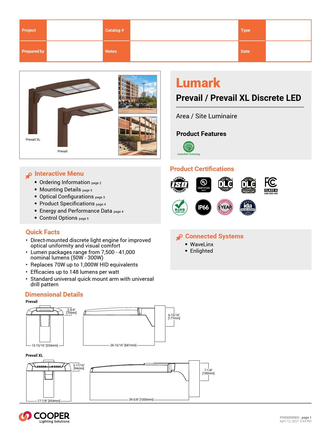
Project Prepared by

Catalog # Notes

Type Date

Prevail XL

Prevail

Interactive Menu
· Ordering Information page 2 · Mounting Details page 3 · Optical Configurations page 3 · Product Specifications page 4 · Energy and Performance Data page 4 · Control Options page 5
Quick Facts
· Direct-mounted discrete light engine for improved optical uniformity and visual comfort
· Lumen packages range from 7,500 - 41,000 nominal lumens (50W - 300W)
· Replaces 70W up to 1,000W HID equivalents · Efficacies up to 148 lumens per watt · Standard universal quick mount arm with universal
drill pattern
Dimensional Details
Prevail
2-3/4" [70mm]

Lumark
Prevail / Prevail XL Discrete LED
Area / Site Luminaire Product Features
LumenSafe Technology
Product Certifications
CLASS A
CAN ICES-005
Connected Systems
· WaveLinx · Enlighted
6-15/16" [177mm]

13-15/16" [354mm]
Prevail XL

3-11/16" [94mm]

26-13/16" [681mm]

17-7/8" [454mm]

39-5/8" [1006mm]

7-1/8" [180mm]

PS500005EN page 1 April 12, 2021 3:43 PM

Lumark

PRV / PRV-XL Prevail Discrete

Ordering Information
SAMPLE NUMBER: PRV-XL-PA4B-740-U-T4W-BZ

Product Family 1, 2 PRV=Prevail

Light Engine

Configuration

Drive Current 3

PA1=1 Panel, 24 LED Rectangle

A=745mA Nominal

PA2=2 Panels, 48 LED Rectangles B=950mA Nominal

PRV-XL=Prevail XL

PA3=3 Panels, 72 LED Rectangles PA4=4 Panels, 96 LED Rectangles

Color Temperature
740=70CRI, 4000K 730=70CRI, 3000K 735=70CRI, 3500K 750=70CRI, 5000K

Voltage

Distribution

U=Universal, 120-277V H=High Voltage, 347-480V 9=347V 8=480V 4

T2R=Type II Roadway T2U=Type II Urban T3=Type III T4W=Type IV Wide 5WQ=Type V Square Wide

Mounting (Included)

Finish

[Blank]=Standard Versatile Arm
MA=Mast Arm
WM=Wall Mount Arm

AP=Grey BK=Black BZ=Bronze DP=Dark Platinum GM=Graphite Metallic WH=White

Options (Add as Suffix)
10K=10kV UL 1449 Fused Surge Protective Device 20MSP=20kV MOV Surge Protective Device 20K=Series 20kV UL 1449 Surge Protective Device HA=50°C High Ambient Temperature HSS=House Side Shield (Factory Installed) 5 L90=Optics Rotated 90° Left R90=Optics Rotated 90° Right PR=NEMA 3-PIN Twistlock Photocontrol Receptacle 6 PR7=NEMA 7-PIN Twistlock Photocontrol Receptacle 6 SPB1=Dimming Occupancy Sensor with Bluetooth Interface, <8' Mounting 23 SPB2=Dimming Occupancy Sensor with Bluetooth Interface, 8'-20' Mounting 23 SPB4=Dimming Occupancy Sensor with Bluetooth Interface, 21'-40' Mounting 23 MS/DIM-L08=Motion Sensor for Dimming Operation, Up to 8' Mounting Height 7, 8, 9 MS/DIM-L20=Motion Sensor for Dimming Operation, 9' - 20' Mounting Height 7, 8, 9 MS/DIM-L40=Motion Sensor for Dimming Operation, 21' - 40' Mounting Height 7, 8, 9 MS-L08=Motion Sensor for ON/OFF Operation, Up to 8' Mounting Height 7, 8, 9 MS-L20=Motion Sensor for ON/OFF Operation, 9' - 20' Mounting Height 7, 8, 9 MS-L40=Motion Sensor for ON/OFF Operation, 21' - 40' Mounting Height 7, 8, 9 ZD=DALI-enabled 4-PIN Twistlock Receptacle 7, 8, 10, 11 ZW=Wavelinx-enabled 4-PIN Twistlock Receptacle 7, 8, 10, 11 SWPD4XX=Wavelinx Wireless Sensor, 7' - 15' Mounting Height 7, 8, 10, 11, 12, 13 SWPD5XX=Wavelinx Wireless Sensor, 15' - 40' Mounting Height 7, 8, 10, 11, 12, 13 LWR-LW=Enlighted Wireless Sensor, Wide Lens for 8' - 16' Mounting Height 7, 8, 14 LWR-LN=Enlighted Wireless Sensor, Narrow Lens for 16' - 40' Mounting Height 7, 8, 14 (See Table Below)=LumenSafe Integrated Network Security Camera 15, 16 CC=Coastal Construction 22

Accessories (Order Separately) 17
PRVWM-XX=Wall Mount Kit 18 PRVMA-XX=Mast Arm Mounting Kit 18 PRVSA-XX=Standard Arm Mounting Kit 18 PRVXLWM-XX=Wall Mount Kit (for Prevail XL) 15 PRVXLMA-XX=Mast Arm Mounting Kit (for Prevail XL) 15 PRVXLSA-XX=Standard Arm Mounting Kit (for Prevail XL) 15 MA1010-XX=Single Tenon Adapter for 3-1/2" O.D. Tenon MA1011-XX=2@180° Tenon Adapter for 3-1/2" O.D. Tenon MA1017-XX=Single Tenon Adapter for 2-3/8" O.D. Tenon MA1018-XX=2@180° Tenon Adapter for 2-3/8" O.D. Tenon HSS-VP=House Side Shield, Vertical Panel 5, 19 HSS-HP=House Side Shield, Horizontal Panel 5, 19 OA/RA1013=Photocontrol Shorting Cap OA/RA1014=NEMA Photocontrol - 120V OA/RA1016=NEMA Photocontrol - Multi-Tap 105-285V OA/RA1201=NEMA Photocontrol - 347V OA/RA1027=NEMA Photocontrol - 480V FSIR-100=Wireless Configuration Tool for Motion Sensor 20 SWPD4-XX=WaveLinx Wireless Sensor, 7' - 15' Mounting Height 11, 12, 13 SWPD5-XX=WaveLinx Wireless Sensor, 15' - 40' Mounting Height 11, 12, 13 WOLC-7P-10A=WaveLinx Outdoor Control Module (7-PIN) 21

NOTES: 1. DesignLights Consortium® Qualified. Refer to www.designlights.org Qualified Products List under Family Models for details. 2. Customer is responsible for engineering analysis to confirm pole and fixture compatibility for applications. Refer to installation instructions and pole white paper WP513001EN for additional support information. 3. Nominal drive currents shown here. For actual drive current by configuration, refer to Power and Lumen tables. 4. Only for use with 480V Wye systems. Per NEC, not for use with ungrounded systems, impedance grounded systems or corner grounded systems (commonly known as Three Phase Three Wire Delta, Three Phase High Leg Delta and Three Phase Corner
Grounded Delta systems). 5. House Side Shield not for use with 5WQ distribution. 6. If High Voltage (H) is specified, use a photocontrol that matches the input voltage used (either 347V or 480V). 7. Option not available with High Voltage (H). Must specify Universal (U), 347V (9), or 480V (8) voltage. 8. Controls system is not available with photocontrol receptacle (PR or PR7) or other controls systems (MS, ZW, ZD or LWR). 9. Utilizes the Wattstopper sensor FSP-211. 10. Sensor passive infrared (PIR) may be overly sensitive when operating below -20°C (-4°F). 11. For the device to be field-configurable, requires WAC Gateway components WAC-PoE and WPOE-120 in appropriate quantities. Only compatible with WaveLinx system and software and requires system components to be installed for operation.
See website for more Wavelinx application information. 12. Replace XX with sensor color (WH, BZ or BK). 13. Requires 4-PIN twistlock receptacle (ZD or ZW) option. 14. Enlighted wireless sensors are factory installed and require network components LWP-EM-1, LWP-GW-1, and LWP-PoE8 in appropriate quantities. See website for application information. 15. Only available in PRV-XL configurations PA3X or PA4X. 16. Not available with High Voltage (H, 8 or 9) or HA options. Consult LumenSafe system product pages for additional details and compatibility information. 17. Replace XX with paint color. 18. Only available in PRV configurations PA1X or PA2X. 19. Must order one per optic/LED when ordering as a field-installable accessory (1, 2, 3 or 4). Refer to House Side Shield reference table for details. 20. This tool enables adjustment to Motion Sensor (MS) parameters including high and low modes, sensitivity, time delay, cutoff and more. Consult your lighting representative for more information. 21. Requires 7-PIN NEMA twistlock photocontrol receptacle (PR7) option. The WOLC-7 cannot be used in conjunction with other controls systems (MS, ZW, ZD or LWR). Only for use at 120-347V. 22. Coastal construction finish salt spray tested to over 5,000-hours per ASTM B117, with a scribe rating of 9 per ASTM D1654. 23. Smart device with mobile application required to change system defaults. See controls section for details.

LumenSafe Integrated Network Security Camera Technology Options (Add as Suffix)

Product Family

Camera Type

Data Backhaul

L=LumenSafe Technology

D=Dome Camera

C=Cellular, Customer Installed SIM Card A=Cellular, Factory Installed AT&T SIM Card V=Cellular, Factory Installed Verizon SIM Card S=Cellular, Factory Installed Sprint SIM Card

E=Ethernet Networking

PS500005EN page 2 April 12, 2021 3:43 PM

Lumark

Mounting Details
Pole Mount Arm (PRV)

1-1/4" [32mm]

4-15/16" [125mm]

6-15/16" [177mm]

4-7/8" [124mm]
4" [102mm]

3" [76mm]

9/16" [15mm] Dia. Hole

Wall Mount (PRV)

PRV / PRV-XL Prevail Discrete

Pole Mount Arm (PRV-XL)
7-1/8" [180mm]

1-7/16" [34mm]
4-7/8" [124mm]
4" [102mm]

Versatile Mount System

5-11/16" [144mm]
Wall Mount (PRV-XL)

3" [76mm]

9-16" [15mm] Dia. Hole

8" [203mm]

7-1/8" [181mm]

8" [203mm]

7" [178mm]

2-3/8" [60mm]

5-1/8" [130mm]
6" [152mm]

7/16" [12mm] Dia. Hole

2-7/8" [74mm]

5" [127mm]
6" [152mm]

13/32" [11mm] Dia. Hole

Mast Arm Mount (PRV)

Mast Arm Mount (PRV-XL)

2-1/2" [64mm]
O.D.

3" 3-5/16" [76mm] [84mm]
O.D. O.D.

6" [153mm]

3-1/4" [83mm]

7-13/32" [188mm]

Mounting Configurations and EPAs
NOTE: For 2 PRV's mounted at 90°, requires minimum 3" square or 4" round pole for fixture clearance. For 2 PRV-XL's mounted at 90°, requires minimum 4" square or round pole for fixture clearance. Customer is responsible for engineering analysis to confirm pole and fixture compatibility for applications.

Wall Mount

Arm Mount Single EPA 0.92 (PRV) EPA 1.12 (PRV-XL)

Arm Mount 2 @ 180° EPA 1.35 (PRV) EPA 2.25 (PRV-XL)

Arm Mount 2 @ 90° EPA 1.42 (PRV) EPA 2.13 (PRV-XL)

Arm Mount 3 @ 90° EPA 1.63 (PRV) EPA 2.52 (PRV-XL)

4-1/8" [104mm]
Arm Mount 4 @ 90° EPA 1.63 (PRV) EPA 2.52 (PRV-XL)

Optical Configurations

PRV-PA1X

PRV-PA2X

PRV-XL-PA3X

PRV-XL-PA4X

Optical Distributions
T2R (Type II Roadway)

T2U (Type II Urban)

T3 (Type III)

T4W (Type IV Wide)

5WQ (Type V Square Wide)

= Distribution with House Side Shield (HSS) = Optical Distribution

PS500005EN page 3 April 12, 2021 3:43 PM

Lumark

PRV / PRV-XL Prevail Discrete

Product Specifications
Construction · Single-piece die-cast aluminum housing · Tethered die-cast aluminum door
Optics · Dark Sky Approved (3000K CCT and warmer only) · Precision molded polycarbonate optics
Electrical · -40°C minimum operating temperature · 40°C maximum operating temperature · >.9 power factor · <20% total harmonic distortion
Energy and Performance Data

· Class 1 electronic drivers have expected life of 100,000 hours with <1% failure rate
· 0-10V dimming driver is standard with leads external to the fixture
Mounting · Versatile, patented, standard mount arm
accommodates multiple drill patterns ranging from 1-1/2" to 4-7/8" (Type M drilling recommended for new installations) · A knock-out on the standard mounting arm enables round pole mounting · Prevail: 3G vibration rated (all arms) · Prevail XL Mast Arm: 3G vibration rated

· Prevail XL Standard Arm: 1.5G vibration rated
Finish · Five-stage super TGIC polyester powder coat paint,
2.5 mil nominal thickness
Shipping Data · Prevail: 20 lbs. (9.09 kgs.) · Prevail XL: 45 lbs. (20.41 kgs.)
Warranty · Five year limited warranty, consult website for
details. www.cooperlighting.com/legal

Power and Lumens (PRV)

Power and Lumens (PRV-XL)

Light Engine

Power (Watts)

Drive Current (mA)

Input Current @ 120V (A)

Input Current @ 277V (A)

Input Current @ 347V (A)

Input Current @ 480V (A)

Distribution

4000K/5000K Lumens

Type II BUG Rating Roadway Lumens per Watt

3000K Lumens 1

4000K/5000K Lumens

Type II Urban

BUG Rating Lumens per Watt

3000K Lumens 1

4000K/5000K Lumens

Type III

BUG Rating Lumens per Watt

3000K Lumens 1

4000K/5000K Lumens

Type IV Wide

BUG Rating Lumens per Watt

3000K Lumens 1

Type V Square Wide

4000K/5000K Lumens BUG Rating Lumens per Watt 3000K Lumens 1

PA1A 54 670 0.45 0.21 0.17 0.12

PA1B 74 930 0.62 0.28 0.23 0.17

PA2A 113 720 0.93 0.41 0.33 0.24

PA2B 151 970 1.26 0.55 0.45 0.33

7,605

9,896

15,811 19,745

B1-U0-G2 B1-U0-G2 B2-U0-G3 B2-U0-G3

141

134

141

131

6,926

9,012

14,399 17,982

7,597

9,886

15,795 19,724

B2-U0-G2 B3-U0-G3 B3-U0-G3 B3-U0-G3

141

134

141

131

6,919

9,003

14,384 17,963

7,575

9,857

15,749 19,667

B1-U0-G2 B2-U0-G3 B3-U0-G3 B3-U0-G3

140

133

141

130

6,899

8,977

14,343 17,911

7,484

9,738

15,560 19,431

B2-U0-G2 B2-U0-G3 B3-U0-G3 B3-U0-G4

139

132

139

129

6,816

8,869

14,170 17,696

7,831

10,190 16,281 20,332

B3-U0-G2 B4-U0-G3 B4-U0-G3 B5-U0-G3

145

138

145

135

7,132

9,280

14,827 18,517

Light Engine

Power (Watts)

Drive Current (mA)

Input Current @ 120V (A)

Input Current @ 277V (A)

Input Current @ 347V (A)

Input Current @ 480V (A)

Distribution

4000K/5000K Lumens

Type II BUG Rating Roadway Lumens per Watt

3000K Lumens 1

4000K/5000K Lumens

Type II Urban

BUG Rating Lumens per Watt

3000K Lumens 1

4000K/5000K Lumens

Type III

BUG Rating Lumens per Watt

3000K Lumens 1

4000K/5000K Lumens

Type IV Wide

BUG Rating Lumens per Watt

3000K Lumens 1

Type V Square Wide

4000K/5000K Lumens BUG Rating Lumens per Watt 3000K Lumens 1

PA3A 172 750 1.44 0.62 0.52 0.39

PA3B 234 980 1.95 0.85 0.70 0.52

PA4A 245 785 2.04 0.93 0.74 0.53

PA4B 303 970 2.53 1.12 0.90 0.65

24,718 30,648 34,067 39,689

B3-U0-G3 B3-U0-G4 B3-U0-G4 B3-U0-G4

144

131

139

131

22,511 27,912 31,025 36,145

24,692 30,616 34,031 39,647

B4-U0-G4 B4-U0-G4 B4-U0-G4 B4-U0-G4

144

131

139

131

22,488 27,882 30,992 36,107

24,621 30,527 33,932 39,532

B3-U0-G4 B3-U0-G5 B3-U0-G5 B4-U0-G5

143

130

138

130

22,423 27,802 30,903 36,002

24,325 30,161 33,525 39,057

B3-U0-G4 B3-U0-G5 B3-U0-G5 B4-U0-G5

141

129

137

129

22,153 27,468 30,531 35,570

25,453 31,559 35,079 40,868

B5-U0-G4 B5-U0-G5 B5-U0-G5 B5-U0-G5

148

135

143

135

23,180 28,741 31,947 37,219

NOTES: 1. For 3000K BUG Ratings, refer to published IES files.

NOTES: 1. For 3000K BUG Ratings, refer to published IES files.

Lumen Maintenance Ambient Temperature Up to 50°C

View PRV Discrete IES files
TM-21 Lumen Maintenance (78,000 Hours) 96.76%

View PRV-XL Discrete IES files

House Side Shield Reference Table

Rotated Optics

Standard
L90 or R90 option

PA1
HSS-VP (qty 1)
HSS-HP (qty 1)

Light Engine Configuration

PA2

PA3

HSS-HP (qty 2)

HSS-HP (qty 3)

HSS-VP (qty 2)

HSS-VP (qty 3)

PA4
HSS-VP (qty 4)
HSS-HP (qty 4)

PS500005EN page 4 April 12, 2021 3:43 PM

After Hours Dim (AHD)

This feature allows photocontrol-enabled luminaires to achieve additional energy savings by dimming during scheduled portions of the night.

The dimming profile will automatically take effect after a "dusk-to-dawn" period has been calculated from the photocontrol input. Specify the

desired dimming profile for a simple, factory-shipped dimming solution requiring no external control wiring. Reference the After Hours Dim

Lumark supplemental guide for additional information.

PRV / PRV-XL Prevail Discrete

Dimming Occupancy Sensor (MS/DIM-LXX and MS-LXX)
Control Options These sensors are factory installed in the luminaire housing. When the MS/DIM-LXX sensor option is selected, the occupancy sensor is connected
to a dimming driver and the entire luminaire dims when there is no activity detected. When activity is detected, the luminaire returns to full light 0o-u10tpVuTth. iTshfiextMureSp/DroIvMidsesen0s-1o0rVisdifmamctiongrywpirreelseeadt stofodr iumsedwoiwthnatloighatpinpgrocoxnimtroaltpealyne5l 0orpoetrhceer ncot nptorowl meretwhoitdh. a time delay of five minutes. The MS-LXX sensor Pishofatocctoonrtyropl r(PeRseatntdoPtRu7rn) Pthhoetolucomnitnroalirreeceopfftaacfletesrpfirovveidme ainfuletxeibsleofsonloutaiocntitvoiteyn.aTblhee"dMusSk/-Xto--LdXawXni"sligahlstiongpbreysseetnfsoinrgfilivgehtmleivneulste. Asdavnadncoendlcyocnotrnoltrsoylsstetmhes csopmepcaifitiebdle nwuitmh NbEeMr oAf7l-ipgihntsetanngdianredss ctoanmbaeiunttilaizinedswteitahdtyheoPuRtp7uretcferoptmactleh.e remaining light engines. Dimming Occupancy Sensor (SPB, MS/DIM-LXX and MS-LXX) These sensors are factory installed in the luminaire housing. When the SPB or MS/DIM sensor options are sTehleecsteedo, tchceulpumanincayirseewnilslodrims idnocwlundaeftserafnivienmteignuratelspohfontooaccetlilvtithyadtecteacntebde. WachteinvaatcetidvitwyiitshdtehteecFteSdI,Rth-1e0lu0maicncaeirsesroetruyrnfos rto"dfuullslkig-htot -oduatpwunt."WchoenntarosleonsrodrafoyrliOgNh/t OhFaFrvoepsetraintigon- (tMheS-fLaXcXt)oirsyspelreecsteedt,itsheOlFuFm. iTnahiereFwSilIlRt-u1r0n0ofifsaaftwerifrievelemssintuoteosl ouftinliozeacdtifvoitry.cThhaensgeioncgcuthpeandciymsmenisnogrsleinvcelul,dteimaneindteelgarya,l psheontsoicteivllitthyaat ncadnobteheacrtivated omproainbraailecmtaievpatpetlericdsa.wtAiiotnhvabthryeieWptaryottgosrftaosmpepmneisrnotgorrcleehmnaonstgeaer/efcaoacntvofairgyiluadrbaetfliaeountlottdooiompl tfmoimrin"igdzuelesvtkhe-tle,ot-cidmoaevwednre"alcagoye,nstpreoanlstotiterivr"dnitayfyoalinrgdhmtoohthauernvretpisnatrginamgh."eeStigePrhBst.smAfvoratoiiolmanbsl8ee'nf-o4sro0ir'O.sSreaqnudirAenthderoSidendseovricCeosn. TfighuerSaPtioBn sensor is factory preset to dim down to approximately 10% power with a time delay of five minutes.

For mounting heights up to 8' (SPB1, -L08) 0

For mounting heights up to 20' (SPB2, -L20) 0

8

5

12

36

24 18

7 50 5 7

18 24

36

Coverage Side Area (Feet)

10

For mounting heights up to 40' (SPB4, -L40W) 0
15

15

20 20 18 15 12 9

63

036

9 12 15 18 20 Coverage Side Area (Feet)

27

40

50

40

30

20

10

0

10

20

30

40

50

Coverage Side Area (Feet)

WaveLinx Wireless Control and Monitoring SystemAvailable in 7-PIN or 4-PIN configurations, the WaveLinx Outdoor control platform operates on a wireless mesh network

based on IEEE 802.15.4 standards enabling wireless control of outdoor lighting. Use the WaveLinx Mobile application for set-up and configuration. At least one Wireless

ALrueamCaoWntarotltlePr r(WoAWC)iriselreeqsusirCedonfotrrofulllafnundcMtioonnaliittyorainndgreSmyostteecmom(LmWuRni-cLaWtioann(dinLcWludRi-nLgNa)djustment of any factory pre-sets).

WTahveeLEinaxtoOnut'dsoLour mCoanWtroal tMtoPdruolep(WowOLeCr-e7dP-1b0yAE)nAlipghhotteodcoinstarocl tohnant eencatebdlesligashttrionngomsoicluotritoimn et-hbaatsecdomscbhiendeusleas tborporaodvidseelOeNc,tiOoFnFoafndendeimrgmyin-egfcfiocnietrnolt oLfEfiDxtluuremsinaires uwtiliitzhinag pa o7w-PeINrfruelceinptteacglrea. tTehde wouitr-eolfe-bsosxsfeunncstoiornsaylistyteismO.NTahtedsuesnk saondr cOoFnFtarot dlsawthne. lighting system in compliance with the latest energy codes and collects

WvaavleuLainbxleWdirealteassaSbeonusot rb(uSWildPiDn4gapnderSfWoPrmD5a)nTcheeasendouutdsoeo. rSsoefntsworasreofafeprpplaicsasitvieoninsfrtaurernd (tPhIeR)gorcacnuuplaanrcdyaatnadiantpohointofocerlml faotricolnostehdrolouogphdaeynliegrhgt ysednassinhgb. oThaerdses and ssepnesocrisalcizaendbeapfapcstotrhyaint smtaallkeed iotrsfiiemldp-ilnestaanlldedhveialpsoimpptilem, tiozeol-tlhesesuinsteegorfabtiounildinitnoglurmesinoauirrecseesq,ubipepyeodnwditlhigthhetinZhga. ga Book 18 compliant 4-PIN receptacle (ZD or ZW). These sensors are factory preset to dim down to approximately 50 percent power after 15 minutes of no activity detected. These occupancy sensors include an integral

photocell for "dusk-to-dawn" control or daylight harvesting that is factory-enabled. A variety of sensor lenses are available to optimize the coverage pattern for mounting

heigFhotrsmforoumnti7n'g-4h0e'.ights from 8' to 16' (LWR-LW)
0

For mounting heights from 16' to 40' (LWR-LN) 0

For mounting heights from 16' to 40' (SWPD) 0

20

20

30

30

1460

40

24

840 30 2108 10 00 10 280 30 40 18

24

CCoovveeraraggeeSSidiedeAAreraea(F(eFeete) t)

40 30 20 10 0 10 20 30 40 Coverage Side Area (Feet)

EWnlaigvhetLedinWxirWeliersesleCsosntOroul atdndooMroLniitgohrintignSgysCtoemnt(rLoWlRM-LoWdaunlde L(WWRO-LNC)-7TPh-1e0EAn)lighted System is a connected lighting solution that combines LED luminaires with
aTnhient7e-gpraintewd wirierelelessssosuentdsoorosrylsitgehmti.nTghecsoenntsroorl cmonotdroulsletheenlaigbhlteinsgWsyasvteeLmininxctoomcpolinatnrcoel woiuthtdtoheorlaatersetae,nseirtgeyacnoddeflsoaondd lcioglhletcintsgv.aWluabvleeLdinatxa caobnoutrtoblusilding poeurftodromoarnlcieghantidnugsue.sSinogftwscahreeadpuplleicsattoionpsrotuvrindteheOgNra, nOuFlaFr adnatda dinitmo minfionrgmcaotionntrtohlrsoubgahseendeorgny adsastrhobnooarmdsicanodr tsipmeceiaslcizheeddauplpessthbaatsmedakoenitasi7mdplaeyawndeheekl.p optimize the use of other resources beyond lighting.

For mounting heights from 8' to 16' (LWR-LW) 0

For mounting heights from 16' to 40' (LWR-LN) 0

20

30

16

40

24

18

8

0

8

18

24

Coverage Side Area (Feet)

40 30 20 10 0 10 20 30 40 Coverage Side Area (Feet)

LumenSafe (LD) The LumenSafe integrated network camera is a streamlined, outdoor-ready camera that provides high definition video surveillance. This IP camera solution is optimally designed to integrate into virtually any video management system or security software platform of choice. No additional wiring is needed beyond providing line power to the luminaire. LumenSafe features factory-installed power and networking gear in a variety of networking options allowing security integrators to design the optimal solution for active surveillance.

Cooper Lighting Solutions 1121 Highway 74 South Peachtree City, GA 30269 P: 770-486-4800 www.cooperlighting.com

© 2021 Cooper Lighting Solutions All Rights Reserved.
Specifications and dimensions subject to change without notice.

PS500005EN page 5 April 12, 2021 3:43 PM
Adobe PDF Library 15.0