
![]() DIALOG® 20 and DIALOG® 10 USB
DIALOG® 20 and DIALOG® 10 USB
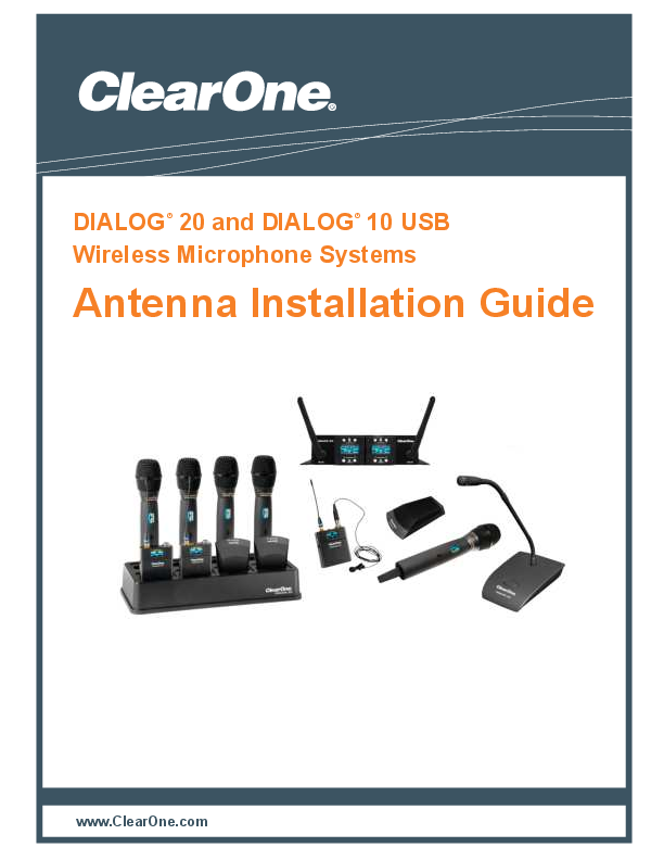
Wireless Microphone Systems 
Antenna Installation Guide
Clearance DIALOG® 20 and DIALOG® 10 USB
The Clearance DIALOG 20 and DIALOG 10 USB Wireless Microphone System Receivers include two, built-in, passive antennas. When using a ClearOne DIALOG 20 or DIALOG 10 USB Antenna Cable Kit, the antennas can be extended to either 10’ or 25’ lengths in each direction easily accommodating most conferencing requirements and room types. These Plenum rated antennas adhere to most municipal fire codes, and therefore, they can be extended inside ceiling crawl spaces for discreet installation. The available transmitters include: Boundary tabletop, Gooseneck podium, Handheld and Belt pack.
Example of “A” and “B” antennas with antenna kit configuration.
Receiver Mounted Antennas:
DIALOG 20 and DIALOG 10 USB Receivers come with two, Plenum rated, dipole antennas.
- Mount the antennas on the front of the receiver using a non-conductive adhesive on the threads of the Female TNC Connector.
- Tilt the antennas slightly outward.

Antenna Cable Kits:
DIALOG 20 and DIALOG 10 USB Antenna Cable Kits are available in two lengths.
The DIALOG Antenna Cable kit can be used to extend the passive, Plenum rated, dipole antennas that are included with the DIALOG 20 and DIALOG 10 USB Receivers.
Choose either a 10’ (ft.) or 25’ (ft.) Antenna Cable Kit.
Includes required hardware. Does not include antennas or adhesive.
 |
|
| 10’ (ft) length for small rooms (RG58 Plenum Cable) SKU: 910-6105-011 | 25’ (ft) length for large rooms (RG8 Plenum Cable) SKU: 910-6105-021 |
Confirm the Box Contains the Following:

Use these cable extension bracket templates to mark the pilot holes.
Hollow Wall Antenna Installation:
- Determine required mounting location.
- Using the antenna extension brackets or the templates (fig. 1; Pg. 2), mark the two (2) mounting hole locations.
- Drill two 5/16” (8mm) pilot holes (Fig 2).

- Fold the anchor (D) in the middle by pressing in middle with finger (Fig. 3).
- Insert anchor in hole and tap flush with a hammer (Fig. 4).
- Use nail or small screwdriver to pop anchor open behind hollow wall (Fig. 5; not necessary for thick or solid walls).
Do not hammer nail or screwdriver.
- Repeat steps 4 – 7 for the second anchor. To avoid interference, only one anchor should be installed vertically.
- Secure antenna extension bracket (A) using two (2) wood screws (B) (Fig 6).
Do not overtighten screws.
Hollow wall anchors (D) may be used as wedge anchors in walls thicker than 3/4” or as expansion anchors in solid walls.
Wood Stud Antenna Installation:
- Determine required mounting location.
- Using the antenna extension bracket or the template (fig. 1; pg. 2), mark two (2) mounting hole locations.
- Drill two 7/64” (2.5mm) pilot holes to a depth of 1-3/4” (45mm).
- Secure the antenna extension bracket (A) to the structure using two (2) wood screws (B) (Fig. 7).
 Fig. 7
Wood Stud Wall Mount Installation
Mounting Antennas to Wall, Ceiling or AV Rack:
- Mount antenna over-head and within line of site to transmitters.
The dipole antenna’s reception is strongest at the sides of the antenna with a null point at the tip. Therefore, it is best to tilt the antenna so that the side faces the transmitters.
• Wall Mount (Fig. 8).
• Ceiling Mount (Fig. 9, 10, 11).
• Ceiling Mount RX with PoE to CONVERGE Pro 2 or Beamforming Mic Array 2 (Fig. 11).
• AV Rack Mount (Fig. 12). Fig. 8 Antenna Bracket Assembly Wall Mounted
 - Separation distance of antennas should be a minimum of 2’ (ft.) and maximum of 30’ (ft.).
- Attach TNC panel mount connector (C) and permanently secure both the antenna and the extension cable (E) to the antenna extension bracket (A) by using a non conductive adhesive on the threads of both sides of the TNC Panel Mount Connector (Fig. 8) .
- Attach the other end of the extension cable to the Dialog 20 Receiver and secure by using a non-conductive adhesive on the threads of the Female TNC Connector.
Repeat steps 1 to 4 for the second antenna and extension cable.
Suggested Mounting Options:
 |
|||
| Fig. 9 Plenum Rated Antennas Mounted in the Crawl Space above the Ceiling Tiles using 3rd party “T-Bracket”. |
Fig. 10 Plenum Rated Antennas Mounted below the Ceiling Tiles. |
Fig. 11 Receiver Mounted on Outside of Ceiling Tile with PoE to CONVERGE Pro 2 or Beamforming Mic Array 2 |
Fig. 12 Antenna Position AV Rack Mounted |
Professional installation is required. Installer is responsible for securing antennas with a nonconductive adhesive and ensuring mounting hardware is appropriate to their particular installation.
CLEARONE LOCATIONS
HEADQUARTERS:
Salt Lake City, UT USA
5225 Wiley Post Way
Suite 500
Salt Lake City, UT 84116
Tel: 801.975.7200
Toll Free: 800.945.7730
Fax: 801.303.5711
e-mail: sales@clearone.com
| EMEA Tel: 44 (0) 1189.036.053 e-mail: global@clearone.com |
APAC Tel: 852.3590.4526 e-mail: global@clearone.com |
| LATAM Tel: 801.974.3621 e-mail: global@clearone.com |
TechSales Tel: 800.707.6694 e-mail: techsales@clearone.com Technical Support Tel: 800.283.5936 e-mail: tech.support@clearone.com |
Other product names may be registered trademarks of their respective owners who do not necessarily endorse Clearance or Clearance’s products. All rights reserved. Information in this document subject to change without notice. © 2022 Clearance. DOC-0307-001 DIALOG20 ANTENNA INSTALLATION GUIDE V6.0 January 04, 2022.
Documents / Resources
 |
ClearOne DIALOG 20 and DIALOG 10 USB Wireless Microphone Systems [pdf] Installation Guide DIALOG 20 and DIALOG 10 USB Wireless Microphone Systems, DIALOG 20 and DIALOG, 10 USB Wireless Microphone Systems, Microphone Systems |
References
-
 Professional AV networking and cloud-based collaboration |Advanced audio conferencing| Video Conferencing- ClearOne
- User Manual


