u blox EMMYW163 WLAN/Bluetooth/NFC host-based multiradio module EMMY-W1 User Manual NEO 7
u-blox AG WLAN/Bluetooth/NFC host-based multiradio module EMMY-W1 NEO 7
u blox >
Contents
- 1. EMMY-W1_User_Manual
- 2. Data Sheet
- 3. EMMY-W1_AntennaReferenceDesign
EMMY-W1_User_Manual
EMMY-W1 series
Host-based multiradio modules with Wi-
Fi, Bluetooth and NFC
User Manual
Abstract
This technical data sheet describes the EMMY-W1 series modules
with Wi-Fi 802.11ac, Bluetooth v4.2 (Bluetooth® Smart Ready) and
Near-Field Communication (NFC) designed for both simultaneous
and independent operations. These modules include an integrated
MAC/baseband processor and RF front-end components and can
connect to a host processor through SDIO 3.0 or high-speed UART
interfaces. A PCM interface is available for Bluetooth audio
applications. These modules are offered in both professional and
automotive grades.
www.u-blox.com
UBX-16015271 - R03

EMMY-W1 series - User Manual
UBX-16015271 - R03 Product Information Page 2 of 46
Document Information
Title
EMMY-W1 series
Subtitle
Host-based multiradio modules with Wi-Fi, Bluetooth and NFC
Document type
User Manual
Document number
UBX-16015271
Revision and date
R03
05-July-2016
Document status
Product Information
Document status explanation
Objective Specification
Document contains target values. Revised and supplementary data will be published later.
Advance Information
Document contains data based on early testing. Revised and supplementary data will be published later.
Early Production Information
Document contains data from product verification. Revised and supplementary data may be published later.
Production Information
Document contains the final product specification.
This document applies to the following products:
Product name
Type number
ROM/FLASH version
PCN / IN reference
EMMY-W161
EMMY-W161-00B-00
EMMY-W161-00B
N/A
EMMY-W161-A
EMMY-W161-00A-00
EMMY-W161-00A
N/A
EMMY-W163
EMMY-W163-00B-00
EMMY-W163-00B
N/A
EMMY-W163-A
EMMY-W163-00A-00
EMMY-W163-00A
N/A
EMMY-W165
EMMY-W165-00B-00
EMMY-W165-00B
N/A
EMMY-W165-A
EMMY-W165-00A-00
EMMY-W165-00A
N/A
u-blox reserves all rights to this document and the information contained herein. Products, names, logos and designs described herein may in
whole or in part be subject to intellectual property rights. Reproduction, use, modification or disclosure to third parties of this document or
any part thereof without the express permission of u-blox is strictly prohibited.
The information contained herein is provided “as is” and u-blox assumes no liability for the use of the information. No warranty, either
express or implied, is given, including but not limited, with respect to the accuracy, correctness, reliability and fitness for a particular purpose
of the information. This document may be revised by u-blox at any time. For most recent documents, visit www.u-blox.com.
Copyright © 2016, u-blox AG.
u-blox® is a registered trademark of u-blox Holding AG in the EU and other countries. ARM® is the registered trademark of ARM Limited in
the EU and other countries.

EMMY-W1 series - User Manual
UBX-16015271 - R03 Product Information Contents
Page 3 of 46
Contents
Contents .............................................................................................................................. 3
1 Functional description .................................................................................................. 5
1.1 Overview .............................................................................................................................................. 5
1.2 Applications .......................................................................................................................................... 5
1.3 Product features ................................................................................................................................... 6
1.4 Block diagrams ..................................................................................................................................... 6
1.5 Product description ............................................................................................................................... 7
1.6 Supported features ............................................................................................................................... 8
1.6.1 Wi-Fi features ................................................................................................................................ 8
1.6.2 Bluetooth features ......................................................................................................................... 8
1.6.3 NFC features ................................................................................................................................. 8
1.6.4 General product features ............................................................................................................... 8
1.6.5 Compliance ................................................................................................................................... 9
1.7 Additional reserved MAC addresses ...................................................................................................... 9
2 Interfaces .................................................................................................................... 10
2.1 Operation mode configuration ........................................................................................................... 10
2.2 SDIO interface .................................................................................................................................... 10
2.2.1 Default speed and High speed modes ......................................................................................... 10
2.2.2 SDR12, SDR25, SDR50 Modes (up to 100 MHz) (1.8 V) ............................................................... 11
2.2.3 SDR104 Mode (208 MHz) (1.8 V) ................................................................................................ 12
2.2.4 DDR50 Mode (50 MHz) (1.8 V) .................................................................................................... 13
2.3 High Speed UART interface ................................................................................................................. 14
2.4 PCM interface ..................................................................................................................................... 15
2.4.1 PCM interface specifications ........................................................................................................ 15
2.5 GPIO interface .................................................................................................................................... 16
3 Pin Definition .............................................................................................................. 18
3.1 Pin description .................................................................................................................................... 18
3.2 Reset configuration............................................................................................................................. 19
4 Electrical specification ................................................................................................ 20
4.1 Absolute maximum ratings ................................................................................................................. 20
4.2 Operating conditions .......................................................................................................................... 20
4.3 Digital pin ratings ............................................................................................................................... 21
4.4 Wi-Fi power consumption ................................................................................................................... 21
4.5 Bluetooth power consumption ........................................................................................................... 22
4.6 NFC power consumption .................................................................................................................... 22
4.7 Radio specifications ............................................................................................................................ 23
4.7.1 Wi-Fi ........................................................................................................................................... 23
4.7.2 Bluetooth .................................................................................................................................... 28

EMMY-W1 series - User Manual
UBX-16015271 - R03 Product Information Contents
Page 4 of 46
4.7.3 LTE co-existence .......................................................................................................................... 28
4.7.4 Near field communication ........................................................................................................... 28
5 Host drivers and firmware ......................................................................................... 30
5.1 General principle ................................................................................................................................ 30
5.2 Supported operating systems .............................................................................................................. 30
5.2.1 Linux ........................................................................................................................................... 30
6 Mechanical specifications .......................................................................................... 31
7 Qualification and approvals ...................................................................................... 32
7.1 Approvals ........................................................................................................................................... 32
7.1.1 European Union regulatory compliance ....................................................................................... 32
7.1.2 FCC compliance .......................................................................................................................... 33
7.1.3 IC compliance.............................................................................................................................. 34
7.2 Approved antennas ............................................................................................................................ 35
7.2.1 Bluetooth antenna ...................................................................................................................... 36
7.2.2 NFC antenna ............................................................................................................................... 36
7.3 FCC and IC IDs (planned) .................................................................................................................... 36
7.4 Certification in other countries ........................................................................................................... 36
8 Product handling ........................................................................................................ 37
8.1 Packaging ........................................................................................................................................... 37
8.1.1 Reels ........................................................................................................................................... 37
8.1.2 Tapes .......................................................................................................................................... 37
8.2 Shipment, storage and handling ......................................................................................................... 37
8.2.1 Moisture sensitivity levels ............................................................................................................. 37
8.2.2 Mounting process and soldering recommendations ..................................................................... 38
8.2.3 ESD handling precautions ............................................................................................................ 39
9 Labeling and ordering information ........................................................................... 40
9.1 Product labeling .................................................................................................................................. 40
9.2 Explanation of codes........................................................................................................................... 41
9.3 Ordering codes ................................................................................................................................... 41
Appendix .......................................................................................................................... 42
A Glossary ...................................................................................................................... 42
Related documents........................................................................................................... 44
Revision history ................................................................................................................ 45
Contact .............................................................................................................................. 46

EMMY-W1 series - User Manual
UBX-16015271 - R03 Product Information Functional description
Page 5 of 46
1 Functional description
1.1 Overview
The EMMY-W1 series provides a complete short range transceiver solution that can easily be integrated into
automotive and industrial applications. The modules are designed for both simultaneous and independent
operation of the following technologies:
IEEE 802.11a/b/g/n/ac payload data rates for Wi-Fi
Dual-mode Bluetooth v4.2
NFC
The EMMY-W1 series is a surface-mount device (SMD) component and can be used as a Wi-Fi micro-access point
supporting up to 10 clients. A coexistence feature on chip level improves parallel use of Bluetooth and Wi-Fi
communication. For highest throughput and performance, a module variant with separated Wi-Fi and Bluetooth
antenna pin is also available.
The modules include an integrated MAC/baseband processor and RF front-end components and can connect to
a host processor through SDIO 3.0 and high-speed UART interfaces. The EMMY-W1 series are offered in
automotive and professional grades (see 9.3 Ordering codes and 1.4 Block diagrams). The automotive grade
variant includes an automotive-qualified (AEC-Q100) chipset. A host driver for Linux 3.x is available free of
charge. The modules are radio type approved
1
for Europe (ETSI R&TTE), US (FCC CFR 47 part 15 unlicensed
modular transmitter approval) and Canada (IC RSS). Regulatory approvals for using this module in Japan, South
Korea, China, Taiwan and Australia will follow.
1.2 Applications
Automotive applications
High definition (HD) video streaming (headrest displays, rear-view camera) and in-car gaming
Rapid sync-n-go applications and fast content download to the vehicle
Hands-free equipment (Bluetooth)
Personalized adjustment of comfort functions through NFC
Industrial applications
Manufacturing floor automation, wireless control terminals and point-to-point backhaul
Outdoor content distribution
Mobile video streaming
Robust wireless connectivity in a broad range of industrial applications
1
Approvals are pending
EMMY-W1 series - User Manual
UBX-16015271 - R03 Product Information Functional description
Page 6 of 46
1.3 Product features
Model
Radio
Interfaces
Power
Connectors
Features
Grade
Wi-Fi 2.4 GHz channels 1-13
Wi-Fi 5 GHz channels 36-165
Wi-Fi IEEE 802.11 version
NFC
Bluetooth qualification
Bluetooth profiles
Max output power at antenna pin
Antenna type
LTE filter
High-speed UART
SDIO 3.0
PCM (Bluetooth audio)
Power supply: 3.0-3.6 V
Solder pins
Micro Access Point
AES hardware support
RF parameters in OTP memory
MAC addresses in OTP memory
Standard
Professional
Automotive
EMMY-W161
•
•
a/b/g/n/ac
•
v4.2
H
18 dBm
1p
•
•
•
•
•
•
•
•
•
•
EMMY-W163
•
•
a/b/g/n/ac
•
v4.2
H
18 dBm
2p
•
•
•
•
•
•
•
•
•
EMMY-W165
•
•
a/b/g/n/ac
•
v4.2
H
18 dBm
1p
•
•
•
•
•
•
•
•
•
H = HCI 1p = One pin for combined external antenna for Bluetooth and Wi-Fi
2p = Two pins for separate external antennas for Bluetooth and Wi-Fi
Table 1: EMMY-W1 series main features summary
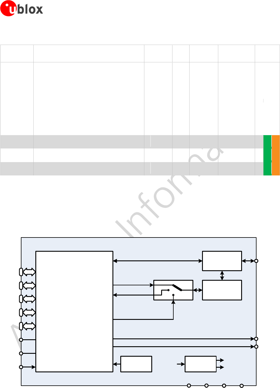
1.4 Block diagrams
The block diagrams of the EMMY-W1 series are provided in this section.
Figure 1: EMMY-W161/EMMY-W165 block diagram - Single antenna variant
MAC/BB/RADIO
2.4GHz WLAN TX
2.4GHz WLAN/BT RX
BT TX
WLAN &
BT ANT
5GHz WLAN TX/RX 5GHz BPF &
DIPLEXER
2.4GHz
BPF
EMMY-W161 / EMMY-W165
SDIO
37.4 MHz
Crystal
VIO1
UART VIO2
PCM VIO2
BT LTE
COEX VIO2
BT LED
WLAN
LED
PDn
SP3T
3.3V VIO1 VIO2 GND
NFC
COIL
VIO2
GPIOs
DC/DC
3.3V
1.8V
1.1V
EMMY-W1 series - User Manual
UBX-16015271 - R03 Product Information Functional description
Page 7 of 46
In EMMY-W161, the band pass filter (2.4 GHz BPF) is a BAW filter that enables co-existence with
LTE. For the variant EMMY-W165, the band pass filter provides no co-existence protection against
a co-located LTE transmitter.
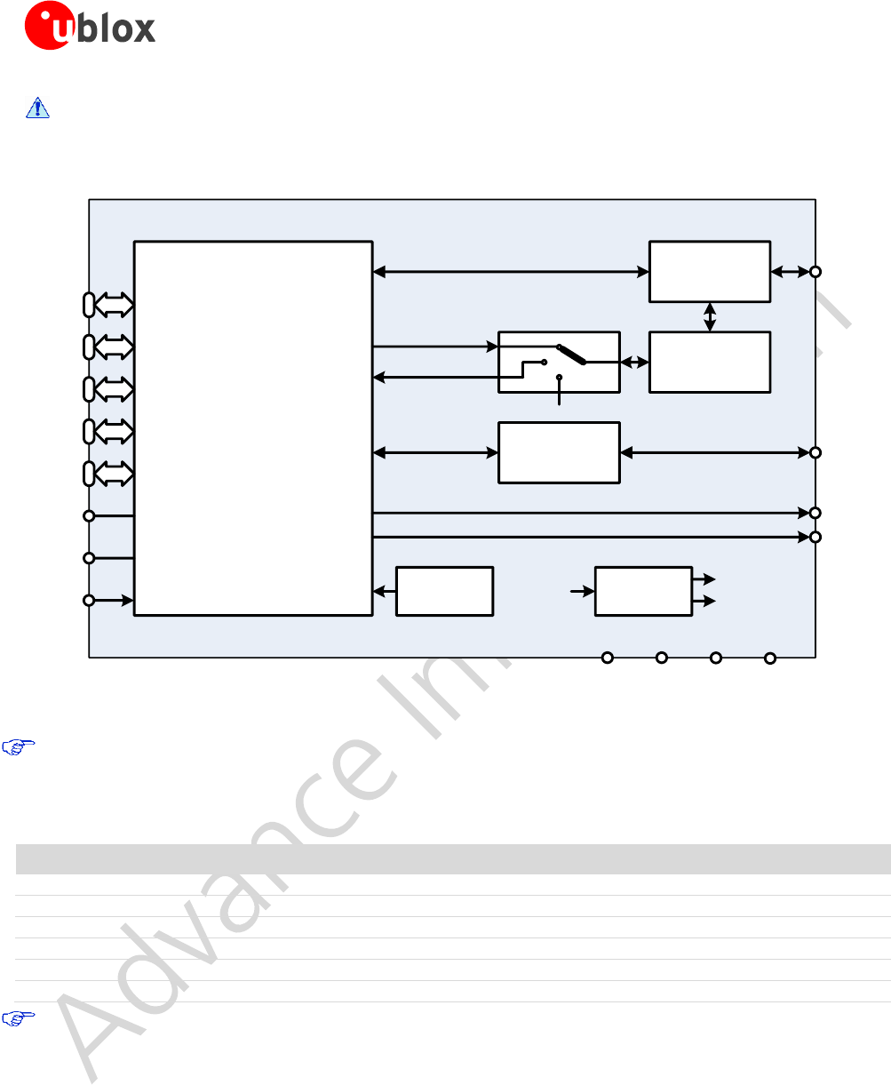
Figure 2: EMMY-W163 block diagram - Dual-antenna variant
In EMMY-W163, the bandpass filters (2.4 GHz BPF) are ceramic bandpass filters. An LTE co-existence
variant is not available in the dual-antenna configuration.
1.5 Product description
Model
Description
EMMY-W161
Professional grade module with 1 combined antenna pin for Wi-Fi and Bluetooth and integrated LTE filter
EMMY-W163
Professional grade module with 2 separate antenna pins for Wi-Fi and Bluetooth (no LTE filter)
EMMY-W165
Professional grade module with 1 combined antenna pin for Wi-Fi and Bluetooth (no LTE filter)
EMMY-W161-A
Automotive grade module with 1 combined antenna pin for Wi-Fi and Bluetooth and integrated LTE filter
EMMY-W163-A
Automotive grade module with 2 separate antenna pins for Wi-Fi and Bluetooth (no LTE filter)
EMMY-W165-A
Automotive grade module with 1 combined antenna pin for Wi-Fi and Bluetooth (no LTE filter)
The EMMY-W161 is recommended for applications that have co-located Wi-Fi, Bluetooth and LTE
antennas and require co-existence of these wireless technologies. This module provides a dedicated BAW
bandpass filter instead of the ceramic bandpass filter. This filter rejects the adjacent LTE bands B40, B7,
B41 and B38. The integrated BAW filter is available only for the single-antenna configuration
(EMMY-W161). The module pinout, operating conditions, and electrical characteristics are identical for all
product variants. Differences in the RF parameters are explained in the Radio specifications section.
MAC/BB/RADIO
2.4GHz WLAN TX
2.4GHz WLAN RX
BT RX/TX
WLAN
ANT
5GHz WLAN TX/RX 5GHz BPF &
DIPLEXER
2.4GHz
BPF
EMMY-W163
SDIO
37.4 MHz
Crystal
VIO1
UART VIO2
PCM VIO2
BT LTE
COEX VIO2
BT LED
WLAN
LED
PDn
2.4GHz
BPF
SP3T
3.3V VIO1 VIO2 GND
NFC
COIL
BT
ANT
VIO2
GPIOs
DC/DC
3.3V
1.8V
1.1V

EMMY-W1 series - User Manual
UBX-16015271 - R03 Product Information Functional description
Page 8 of 46
1.6 Supported features
1.6.1 Wi-Fi features
Wi-Fi standards: IEEE 802.11a/b/g/n/ac/d/e/h/i/k
2
/r/v2/w
Simultaneous client and access point operation (up to 10 clients supported)
Support of Wi-Fi direct mode
IEEE 802.11ac 1x1 antenna configuration
IEEE 802.11 PHY data rates up to 433 Mbps
64- and 128-bit AES hardware encryption engine
WAPI encryption is supported by hardware
SDIO 3.0 host interface for Wi-Fi
1.6.2 Bluetooth features
Bluetooth v4.2 with Bluetooth Low Energy and Classic Bluetooth v2.1+EDR over SDIO or high-speed
UART interface
PCM interface for audio
MWS/LTE coexistence serial transport interface for connecting an external and co-located LTE device
3
1.6.3 NFC features
NCI 1.0 support according to NFC Forum specification
NFC support through SDIO or UART
Full protocol support for ISO 14443A/B, ISO 15693
4
, ISO 18092, NFCIP-2, NFC forum, EMV contactless
targets with data rates up to 848 Kbps
Deep Sleep
Proprietary Low-Power Target Detection mode to reduce standby current consumption
On-Host card emulation: supported in NFC A, B, F and V technologies
Off-Host card emulation with UICCs and Embedded SEs (availability is package dependent):
o ETSI TS 102 613: SWP/CLT ISO14443 Type A (Mifare) and ISO18093 212/424 kbps passive
mode (FeliCa).
o ETSI TS 102 622: SWP/HCI ISO14443A/B and ISO18092 212/424 kbps passive mode
o DCLB
Compliant with EMVCo book D (Contactless Communication Protocol)
Reader/Writer, card emulation, and Peer-to-peer (P2P) modes
Programmable carrier detection level for card emulation mode
Programmable field detection level for RF anti-collision when operating as reader or active target
UART host interface support (shared with Bluetooth when operating)
1.6.4 General product features
Driver support for Linux
Low-power and sleep modes for Bluetooth and Wi-Fi core
Coexistence arbitration for Wi-Fi/Bluetooth/LE/NFC/LTE operation
Small footprint (19.8 mm x 13.8 mm), LGA package
Product variant with integrated LTE co-location filter available
Automotive qualification tests (climatic, mechanical, and operating life tests) according ISO 16750-4
planned
2
Supported by hardware but not supported by firmware currently.
3
Available on request
4
For ISO 15693 VICC mode, the maximum supported 10-90% rise/fall times for receiving 10% ASK modulation is 1.18 μs.

EMMY-W1 series - User Manual
UBX-16015271 - R03 Product Information Functional description
Page 9 of 46
1.6.5 Compliance
RoHS compliant
Radio type approvals for Europe, USA, Canada, Japan, Korea, Taiwan, China and Australia
5
1.7 Additional reserved MAC addresses
The EMMY-W1 module series has four unique consecutive MAC addresses reserved for each module, from
which the first two addresses are already stored in the configuration during production. The first address is used
for the Bluetooth communication while the second address is configured for Wi-Fi communication. The Data
Matrix Code on the label includes the Bluetooth MAC address (see section 9). The remaining two MAC
addresses are not used in the manufacturing configuration, but are reserved for usage with the module.
MAC address
Assignment
Last two bits of MAC address
Example
Module1, address 1
Bluetooth
0b00
D4:CA:6E:44:00:04
Module1, address 2
Wi-Fi
0b01
D4:CA:6E:44:00:05
Module1, address 3
(free for use)
0b10
D4:CA:6E:44:00:06
Module1, address 4
(free for use)
0b11
D4:CA:6E:44:00:07
Module2, address 1
Bluetooth
0b00
D4:CA:6E:44:00:08
Module2, address 2
Wi-Fi
0b01
D4:CA:6E:44:00:09
Module2, address 3
(free for use)
0b10
D4:CA:6E:44:00:0A
Module2, address 4
(free for use)
0b11
D4:CA:6E:44:00:0B
Table 2: MAC address assignment
5
Approvals are pending.
EMMY-W1 series - User Manual
UBX-16015271 - R03 Product Information Interfaces
Page 10 of 46
2 Interfaces
2.1 Operation mode configuration
EMMY-W1 series module uses the GPIO_3 and GPIO_2 pins as host interface configuration input to set the
desired operation mode following a reset. The definitions of these pins are changed to their usual functions after
reset. When you need to configure the pins for a certain module operation mode, you need to provide a 100 kΩ
pull down resistor to the ground. No external circuitry is required to set a configuration pin to high logical level.
External reset is not needed for proper operation due to internal power-up reset logic though it can be used by
the host controller through the PDn pin (active low) in case of an abnormal module behavior.
After reset, GPIO_3 and GPIO_2 pins can be used as open drain outputs (depending on firmware/driver version)
for Bluetooth and Wi-Fi activity LED indicators, but simultaneous usage of an LED connected to 3.3 V power line
and a pull-down resistor is not allowed (LED acts as a strong pull-up circuitry). Do not connect LED if you need
the pull-down resistors.
Depending on the firmware or driver used, you can use either one or both host interface operation modes:
GPIO_3
GPIO_2
Wi-Fi
Bluetooth/NFC
Number of SDIO functions
0
0
SDIO
UART
1 (Wi-Fi)
0
1
SDIO
SDIO
3 (Wi-Fi, Bluetooth and NFC)
1
0
SDIO
UART
1 (Wi-Fi)
1
1
SDIO
SDIO
3 (Wi-Fi, Bluetooth and NFC)6
Table 3: Module configuration
2.2 SDIO interface
EMMY-W1 series modules support an SDIO device interface that conforms to the industry standard SDIO 3.0
Full-Speed specification (4-bit SDIO up to 208 MHz) and allows a host controller using the SDIO bus protocol to
access the Wi-Fi and Bluetooth functions. The interface supports 4-bit SDIO transfer mode at the full clock range
of 0 to 208 MHz.
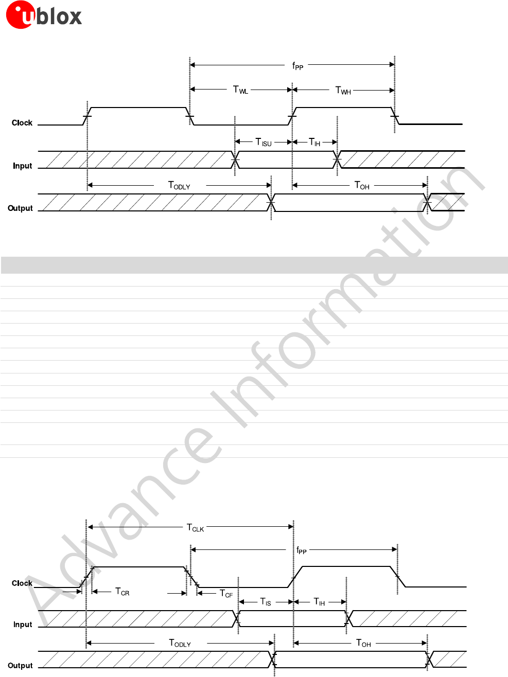
2.2.1 Default speed and High speed modes
Figure 3: SDIO protocol timing diagram- Default speed mode (3.3 V)
6
Default configuration. It is possible to use connected LEDs to both the pins.
EMMY-W1 series - User Manual
UBX-16015271 - R03 Product Information Interfaces
Page 11 of 46
Figure 4: SDIO protocol timing diagram – High speed mode (3.3 V)
Symbol
Parameter
Condition
Min.
Typ
Max.
Units
fPP
Clock frequency
Normal
0
-
25
MHz
High speed
0
-
50
MHz
TWL
Clock low time
Normal
10
-
-
ns
High speed
7
-
-
ns
TWH
Clock high time
Normal
10
-
-
ns
High speed
7
-
-
ns
TISU
Input setup time
Normal
5
-
-
ns
High speed
6
-
-
ns
TIH
Input hold time
Normal
5
-
-
ns
High speed
2
-
-
ns
TODLY(max)
Maximal Output delay time
Normal
-
14
ns
TODLY(min)
Minimal Output delay time
Normal
-
0
ns
TODLY
Output delay time CL ≤ 40 pF
(1 card)
Normal
-
14
ns
TOH
Output hold time
High speed
2.5
-
-
ns
Table 4: SDIO timing data – Default speed, High speed modes (3.3 V)
2.2.2 SDR12, SDR25, SDR50 Modes (up to 100 MHz) (1.8 V)
Figure 5: SDIO protocol timing diagram – SDR12, SDR25, SDR50 modes (up to 100 MHz) (1.8 V)
EMMY-W1 series - User Manual
UBX-16015271 - R03 Product Information Interfaces
Page 12 of 46
Symbol
Parameter
Condition
Min.
Typ
Max.
Units
fPP
Clock frequency
SDR12/25/50
25
-
100
MHz
TIS
Input setup time
SDR12/25/50
3
-
-
ns
TIH
Input hold time
SDR12/25/50
0.8
-
-
ns
TCLK
Clock time
SDR12/25/50
10
-
40
ns
TCR, TCF,
Rise time, fall time
TCR, TCF < 2 ns (max) at 100 MHz
CCARD = 10 pF
SDR12/25/50
-
0.2*TCLK
ns
TODLY
Output delay time
CL ≤ 30 pF
SDR12/25/50
-
7.5
ns
TOH
Output hold time
CL = 15 pF
SDR12/25/50
1.5
-
-
ns
Table 5: SDIO timing data – SDR12, SDR25, SDR50 modes (up to 100 MHz) (1.8 V)
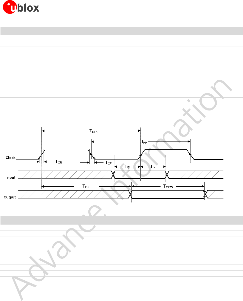
2.2.3 SDR104 Mode (208 MHz) (1.8 V)
Figure 6: SDIO protocol timing diagram – SDR104 mode (208 MHz)
Symbol
Parameter
Condition
Min.
Typ
Max.
Units
fPP
Clock frequency
SDR104
0
-
208
MHz
TIS
Input setup time
SDR104
1.4
-
-
ns
TIH
Input hold time
SDR104
0.8
-
-
ns
TCLK
Clock time
SDR104
4.8
-
-
ns
TCR, TCF,
Rise time, fall time
TCR, TCF < 0.96 ns (max) at 208 MHz
CCARD = 10 pF
SDR104
-
0.2*TCLK
ns
TOP
Card output phase
SDR104
0
-
10
ns
TODW
Output timing of variable data window
SDR104
2.88
-
-
ns
Table 6: SDIO timing data – SDR104 mode (208 MHz)
EMMY-W1 series - User Manual
UBX-16015271 - R03 Product Information Interfaces
Page 13 of 46
2.2.4 DDR50 Mode (50 MHz) (1.8 V)
Figure 7: SDIO CMD timing diagram – DDR50 mode (50 MHz)
Figure 8: SDIO DAT[3:0] timing diagram – DDR50 mode (50 MHz)

EMMY-W1 series - User Manual
UBX-16015271 - R03 Product Information Interfaces
Page 14 of 46
Symbol
Parameter
Condition
Min.
Typ
Max.
Units
Clock
TCLK
Clock time
50 MHz (max) between rising edges
DDR50
20
ns
TCR, TCF,
Rise time, fall time
TCR, TCF < 4.00 ns (max) at 50 MHz
CCARD = 10 pF
DDR50
0.2*TCLK
ns
Clock Duty
DDR50
45
55
%
CMD Input (referenced to clock rising edge)
TIS
Input setup time
CCARD ≤ 10 pF (1 card)
DDR50
6
ns
TIH
Input hold time
CCARD ≤ 10 pF (1 card)
DDR50
0.8
ns
CMD Output (referenced to clock rising edge)
TODLY
Output delay time during data transfer mode
CL ≤ 30 pF (1 card)
DDR50
13.7
ns
TOHLD
Output hold time
CL ≥ 15 pF (1 card)
DDR50
1.5
ns
DAT[3:0] Input (referenced to clock rising and falling edges)
TIS2x
Input setup time
CCARD ≤ 10 pF (1 card)
DDR50
3
ns
TIH2x
Input hold time
CCARD ≤ 10 pF (1 card)
DDR50
0.8
ns
DAT[3:0] Output (referenced to clock rising and falling edges)
TODLY2x (max)
Output delay time during data transfer mode
CL ≤ 25 pF (1 card)
DDR50
7.0
ns
TODLY2x (min)
Output hold time
CL ≥ 15 pF (1 card)
DDR50
1.5
ns
Table 7: SDIO timing data – DDR50 mode (50 MHz)
2.3 High Speed UART interface
The EMMY-W1 series modules support a high speed Universal Asynchronous Receiver/Transmitter (UART)
interface in compliance with the industry standard 16550 specification. The main features of the UART interface
are:
FIFO mode permanently selected for transmit and receive operations
2 pins for transmit and receive operations
2 flow control pins
Interrupt triggers for low-power, high throughput operation
High throughput (4 Mbps)
The UART interface operation includes:
Uploading the firmware to the module
Supporting data input/output operation for peripheral devices connected through a standard UART
interface
Baud Rate
1200
38400
460800
1500000
3000000
2400
57600
500000
1843200
3250000
4800
76800
921600
2000000
3692300
9600
115200
1000000
2100000
4000000
19200
230400
1382400
2764800
Table 8: Supported UART Baud rates
EMMY-W1 series - User Manual
UBX-16015271 - R03 Product Information Interfaces
Page 15 of 46
2.4 PCM interface
The EMMY-W1 series modules support a Pulse Code Modulation (PCM) interface that provides:
Master or slave mode
PCM bit width size of 8 bits or 16 bits
Up to 4 slots with configurable bit width and start positions
Short frame and long frame synchronization
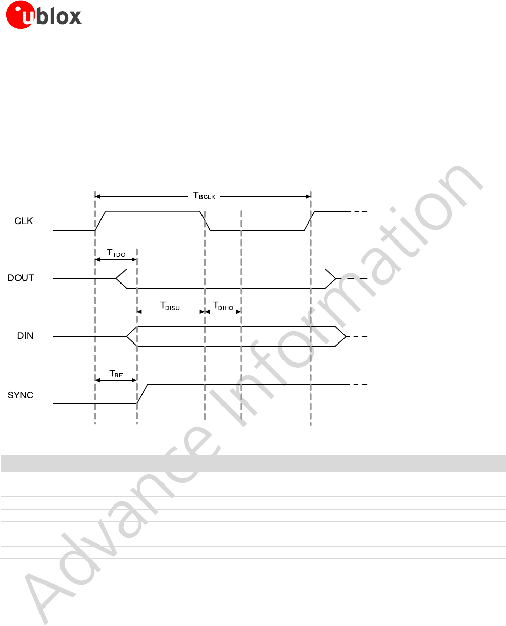
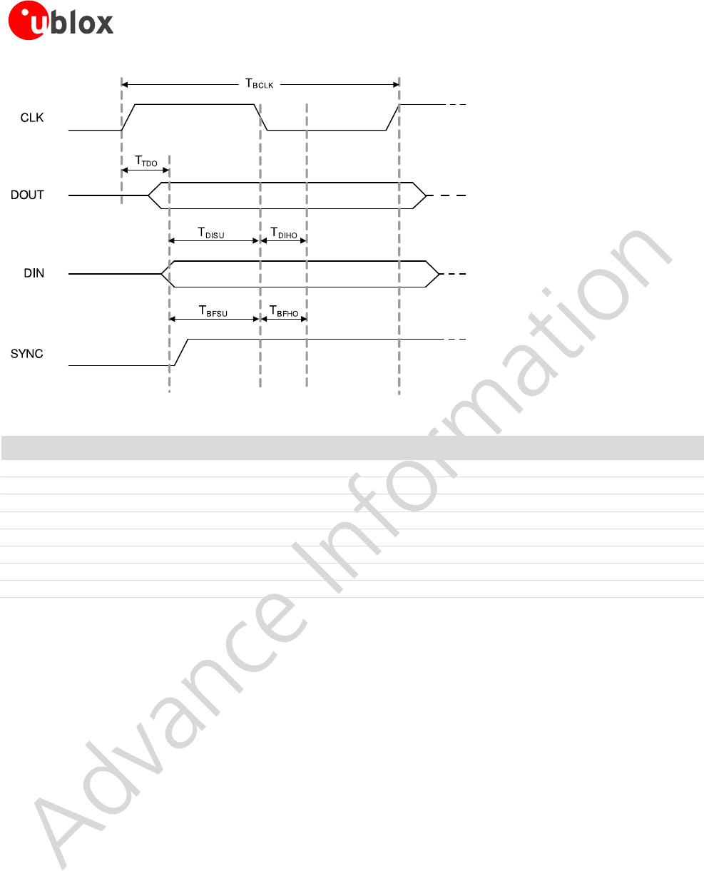
2.4.1 PCM interface specifications
Figure 9: PCM timing specification – Master mode
Symbol
Parameter
Condition
Min.
Typ
Max.
Units
FBCLK
-
-
-
2/2.048
-
MHz
Duty Cycle BCLK
-
-
0.4
0.5
0.6
-
TBCLK rise/fall
-
-
-
3
-
Ns
TDO
-
-
-
-
15
ns
TDISU
-
-
20
-
-
ns
TDIHO
-
-
15
-
-
ns
TBF
-
-
-
-
15
ns
Table 9: PCM timing specification – Master mode
EMMY-W1 series - User Manual
UBX-16015271 - R03 Product Information Interfaces
Page 16 of 46
Figure 10: PCM timing specification – Slave mode
Symbol
Parameter
Condition
Min.
Typ
Max.
Units
FBCLK
-
-
-
2/2.048
-
MHz
Duty Cycle BCLK
-
-
0.4
0.5
0.6
-
TBCLK rise/fall
-
-
-
3
-
ns
TDO
-
-
-
-
30
ns
TDISU
-
-
15
-
-
ns
TDIHO
-
-
10
-
-
ns
TBFSU
-
-
15
-
-
ns
TBFHO
-
-
10
-
-
ns
Table 10: PCM timing specification – Slave mode
2.5 GPIO interface
The General-Purpose I/O (GPIO) interface is used to implement user defined input and output signals to and from
the 88W8887 chip such as external interrupts and other user-defined I/Os. Main features of the GPIO interface
include:
User-defined GPIO (each I/O configured to either input or output)
Each GPIO independently controlled
Each I/O configurable to output bit from GPIO_OUT
The general functions associated with each GPIO pin is shown in Table 11:

EMMY-W1 series - User Manual
UBX-16015271 - R03 Product Information Interfaces
Page 17 of 46
GPIO
Function
GPIOP Pin
0
1
2
3
4
5
6
7
8
9
10
11
12
13
14
15
16
17
General
Input
X
X
X
X
X
X
X
X
X
X
X
X
X
X
X
X
X
X
Output
X
X
X
X
X
X
X
X
X
X
X
X
X
X
X
X
X
X
LEDs
LED output7
-
-
X
X
-
-
-
-
-
-
-
-
-
-
-
-
-
-
Interrupts
Input
X
X
X
X
X
X
X
X
X
X
X
X
X
X
X
X
X
X
Table 11: GPIO Functions – GPIO [17:14], [12:0]
GPIO_12 is not available.
7
GPIO [2] is used for Wi-Fi activity while GPIO [3] is used for Bluetooth activity.
EMMY-W1 series - User Manual
UBX-16015271 - R03 Product Information Pin Definition
Page 18 of 46
3 Pin Definition
3.1 Pin description
Figure 11: Pin assignment
No
Pin name
Pin type
Supply domain
Description
1
GND
Ground
-
Ground
2
NC
-
Reserved, do not connect
3
NC
-
Reserved, do not connect
4
NC
-
Reserved, do not connect
5
GPIO_0
I/O
VIO2
BT2HOST_WAKEUP (Output)
6
GPIO_1
I/O
VIO2
WL2HOST_WAKEUP (Output)
7
GPIO_14
I/O
VIO2
HOST2WL_WAKEUP (Input)
8
GPIO_15
I/O
VIO2
HOST2BT_WAKEUP (Input)
9
GPIO_16
I/O
VIO2
UART_LTE_SIN (Input)
10
GPIO_17
I/O
VIO2
UART_LTE_SOUT (Output)
11
GPIO_4
I/O
VIO2
PCM_DIN (Input)
12
GPIO_5
I/O
VIO2
PCM_DOUT (Output)
13
GPIO_6
I/O
VIO2
PCM_CLK (Input if slave, Output if master)
14
GPIO_7
I/O
VIO2
PCM_SYNC (Input if slave, Output if master)
15
GND
Ground
-
Ground
16
GND
Ground
-
Ground
17
SD_CLK
I
VIO1
SDIO Clock input
18
SD_CMD
I/O
VIO1
SDIO Command line
19
SD_D0
I/O
VIO1
SDIO Data line bit [0]
20
SD_D1
I/O
VIO1
SDIO Data line bit [1]
21
SD_D2
I/O
VIO1
SDIO Data line bit [2]
22
SD_D3
I/O
VIO1
SDIO Data line bit [3]
GND
EMMY-W1
SD_CLK
SD_CMD
SD_D0
SD_D1
SD_D2
SD_D3
GND
GND
3V3
VIO1
VIO2
PDn
GPIO_8
GPIO_9
GPIO_10
29
30
31
25
26
27
28
24
46
45
44
43
42
41
40
39
GND
ANT2
GND
GND
GND
GND
ANT1
GND
6
5
4
3
2
1
GND
Reserved
Reserved
Reserved
GPIO_0
GPIO_1
7
GPIO_14
8
GPIO_15
9
GPIO_16
10
GPIO_17
11
GPIO_4
12
GPIO_5
13
GPIO_6
14
GPIO_7
15
GND
16
17
18
19
20
21
22
23
GPIO_11
32
GPIO_3
33
GPIO_2
34
GND
35
NFC_ANT_N
36
NFC_ANT_P
37
GND
38

EMMY-W1 series - User Manual
UBX-16015271 - R03 Product Information Pin Definition
Page 19 of 46
No
Pin name
Pin type
Supply domain
Description
23
GND
Ground
-
Ground
24
GND
Ground
-
Ground
25
3V3
Power
3.3V
3.3V Power supply (2.97 V - 3.63 V)
26
VIO1
Power
VIO1
VIO1 Power supply (1.62V - 1.98 V, 2.97 V - 3.63 V)
27
VIO2
Power
VIO2
VIO2 Power supply (1.62V - 1.98 V, 2.97 V - 3.63 V)
28
PDn
Input
-
Full power down(active low)8
29
GPIO_8
I/O
VIO2
UART_SOUT (Output)
30
GPIO_9
I/O
VIO2
UART_SIN (Input)
31
GPIO_10
I/O
VIO2
UART_CTSn (Input)
32
GPIO_11
I/O
VIO2
UART_RTSn (Output)
33
GPIO_3
I/O
3.3V
LED_OUT_BT (Output) - BT indicator, Configuration pin9
34
GPIO_2
I/O
3.3V
LED_OUT_WLAN (Output) - WLAN indicator, Configuration pin9
35
GND
Ground
-
Ground
36
NFC_ANT_N
I/O, RF
3.3V
NFC Coil Antenna, negative I/O pin
37
NFC_ANT_P
I/O, RF
3.3V
NFC Coil Antenna, positive I/O pin
38
GND
Ground
-
Ground
39
GND
Ground
-
Ground
40
ANT2
I/O, RF
-
Bluetooth antenna only in case of EMMY-W163 module. Not connected in
case of EMMY-W161 or EMMY-W165 module10
41
GND
Ground
-
Ground
42
GND
Ground
-
Ground
43
GND
Ground
-
Ground
44
GND
Ground
-
Ground
45
ANT1
I/O, RF
-
Wi-Fi + Bluetooth antenna in case of single-antenna module. Wi-Fi antenna
only in case of dual-antenna module10
46
GND
Ground
-
Ground
-
Exposed pin
Ground
-
Six Ground/Thermal exposed pins, connect to the ground
Table 12: EMMY-W1 series pin description
3.2 Reset configuration
The EMMY-W1 is reset to its default operating state under the following conditions:
Power-on reset (POR) – Module receives power 3V3 supplies rise (triggers internal POR circuit)
Software/Firmware reset
External pin assertion (PDn) will generate POR.
8
High input impedance pin for minimizing shutdown current consumption. The pin shall be driven by the host controller or/and connected
via 51 kΩ (or less) pull-up resistor to the 3.3 V supply rail.
9
Possible to use as an LED output depending on the firmware and driver version. In this case, the module pin acts as an open drain output
and the whole LED circuitry must be supplied from 3.3 V power line. A LED current limiting resistor should be used; maximum sink current to
the ground is 10 mA. These pins can also be used for host interface configuration. See Operation mode configuration section.
10
Pin protected from the static electricity by internal DC feed to the ground.

EMMY-W1 series - User Manual
UBX-16015271 - R03 Product Information Electrical specification
Page 20 of 46
4 Electrical specification
Stressing the device above one or more of the ratings listed in the Absolute Maximum Rating
section may cause permanent damage. These are stress ratings only. Operating the module at
these or at any conditions other than those specified in the Operating conditions section
(section 4.2) of the specification should be avoided. Exposure to Absolute Maximum Rating
conditions for extended periods may affect device reliability.
Operating condition ranges define those limits within which the functionality of the device is guaranteed.
Where application information is given, it is advisory only and does not form part of the specification.
4.1 Absolute maximum ratings
Symbol
Description
Min.
Typ
Max.
Units
3V3
Power supply voltage 3.3 V
-
3.3
4.0
V
VIO1
I/O supply voltage 1.8 V
1.8
2.2
V
I/O supply voltage 3.3 V
3.3
4.0
V
VIO2
I/O supply voltage 1.8 V
-
1.8
2.2
V
I/O supply voltage 3.3 V
3.3
4.0
V
TSTORAGE
Storage temperature
-40
+85
ºC
Table 13: Absolute maximum ratings
The product is not protected against overvoltage or reversed voltages. If necessary, voltage
spikes exceeding the power supply voltage specification given in table above must be limited to
values within the specified boundaries by using appropriate protection devices.
4.2 Operating conditions
Symbol
Parameter
Min.
Typ
Max.
Units
3V3
Power supply voltage 3.3 V
2.97
3.3
3.63
V
VIO1
I/O supply voltage 1.8V/3.3 V
1.62
1.8
1.98
V
2.97
3.3
3.63
V
VIO2
I/O supply voltage 1.8V/3.3 V
1.62
1.8
1.98
V
2.97
3.3
3.63
V
VDD_NFC
NFC antenna input voltage (pins NFC_ANT_P/N)
-
-
3.6
V
IANT_NFC
NFC antenna peak input current (pins NFC_ANT_P/N))
-
-
400
mA
TA
Ambient operating temperature
-40
-
+85
ºC
Ripple Noise
Peak-to-peak voltage ripple on 3V3, VIO1 or VIO2
supply line. The values have been determined in a
frequency range from 10 KHz to > 2 MHz [3].
20
-
mV
Table 14: Operating conditions
Parameter
Min.
Typ
Max.
Units
Storage temperature
-40
+85
ºC
Operation temperature
-40
+85
ºC
Table 15: Temperature range

EMMY-W1 series - User Manual
UBX-16015271 - R03 Product Information Electrical specification
Page 21 of 46
4.3 Digital pin ratings
Symbol
Parameter
Min.
Max.
Units
VIH
Input high voltage
0.7*VIO
VIO+0.4
V
VIL
Input low voltage
-0.4
0.3*VIO
V
VHYS
Input hysteresis
100
-
mV
VOH
Output high voltage
VIO-0.4
-
V
VOH
Output low voltage
-
0.4
V
Table 16: Digital pin ratings for VIO1 and VIO2 supply domains
4.4 Wi-Fi power consumption
Operation mode:
2.4 GHz Wi-Fi TX/RX with BT and NFC in Deep Sleep mode
Average current, mA11
Peak current, mA12
RX Idle Default
52
64
RX 11 Mbps
50
62
TX 11 Mbps (Normal power mode, 18 dBm)
290
420
TX 11 Mbps (Low power mode, 10 dBm)
184
RX 54 Mbps
54
68
TX 54 Mbps (15 dBm)
260
320
TX 54 Mbps (8 dBm)
170
RX 11n MCS7 (HT20)
65
TX 11n MCS7 (HT20, 15 dBm)
260
TX 11n MCS7 (HT20, 8 dBm)
174
Operation mode:
5 GHz Wi-Fi TX/RX with BT and NFC in Deep Sleep mode
Average current, mA11
Peak current, mA12
RX 54 Mbps
67
75
TX 54 Mbps (12 dBm)
280
320
TX 54 Mbps (8 dBm)
196
RX MCS7 (HT20)
78
TX MCS7 (HT20, 12 dBm)
282
TX MCS7 (HT20, 8 dBm)
202
RX MCS7 (HT40)
89
TX MCS7 (HT40, 10 dBm)
270
TX MCS7 (HT40, 8 dBm)
214
RX MCS7 (VHT80)
112
TX MCS7 (VHT80, 11 dBm)
360
RX MCS8 (VHT20)
82
TX MCS8 (VHT20, 11 dBm)
265
RX MCS8 (VHT40)
105
TX MCS8 (VHT40, 10 dBm)
265
RX MCS8 (VHT80)
114
TX MCS8 (VHT80, 8 dBm)
356
RX MCS9 (VHT40)
104
TX MCS9 (VHT40, 10 dBm)
263
RX MCS9 (VHT80)
120
TX MCS9 (VHT80, 8 dBm)
348
11
Supply 3.3V. Wi-Fi client mode. Numbers obtained from IPERF UDP traffic.
12
Maximum peak current for the worst supply conditions

EMMY-W1 series - User Manual
UBX-16015271 - R03 Product Information Electrical specification
Page 22 of 46
Operation mode:
Power save modes
Average current, mA
Power Down
0.03
WiFi and BT both in Deepsleep
0.13
WiFi DTIM 1 and BT Deepsleep
1.14
WiFi DTIM 3 and BT Deepsleep
0.47
WiFi DTIM 5 and BT Deepsleep
0.34
Table 17: Wi-Fi power consumption
4.5 Bluetooth power consumption
Bluetooth mode with Wi-Fi and NFC in deep sleep mode
TX @ 0dBm
Average current, mA13
Deep Sleep Mode
0.125
BT idle (Sleep Mode)
4.23
Power Down
0.03
SCO HV3 Peak TX
18.75
SCO HV3 Peak RX
16.50
HV3 SCO mode ACL sniff 0x800
7.57
eSCO link, Master (2-EV3), ACL sniff 0x800
6.57
eSCO link, Master (EV3), ACL sniff 0x800
7.69
ACL (data pump) DH1
11.60
ACL (data pump) DH3
14.60
ACL (data pump) DH5
16.40
ACL Link, master sniff mode, interval=1.28s (800)
0.186
ACL Link, master sniff mode, interval=500ms (320)
0.278
SCO HV3 Average TX @ 4 dBm (external antenna)
7.83
SCO HV3 Average RX @ 4 dBm (external antenna)
22.00
Interlaced scan (= P&I scan)
0.372
Page & Inquiry scan
0.372
Page Scan
0.257
Inquiry Scan
0.257
LE Advertise @ 1.28s interval
0.150
Peak LE TX
18.00
Peak LE RX
16.00
LE Link (interval=400=1.28s)
0.154
LE Link (interval=320=1.00s)
0.155
LE Scan (interval=800=1.28s)
0.231
LE Scan (interval=640-1.00s)
0.262
Table 18: Bluetooth power consumption
4.6 NFC power consumption
Operation Mode
Average current, mA
3V3
TAG Type 1
90
TAG Type 2
95
TAG Type 3
85
TAG Type 4A
100
Table 19: NFC power consumption
13
Supply 3.3V, Average consumption current if not specified otherwise.

EMMY-W1 series - User Manual
UBX-16015271 - R03 Product Information Electrical specification
Page 23 of 46
4.7 Radio specifications
4.7.1 Wi-Fi
The EMMY-W1 series modules support Wi-Fi standards IEEE 802.11a/b/g/n/ac in 2.4 GHz and 5 GHz radio
bands. In the 2.4 GHz band, the EMMY-W1 supports 802.11b/g/n while in 5 GHz band, it supports
802.11a/n/ac.
Parameter
Operation Mode
Specification
RF Frequency range
802.11b/g/n
2.400 – 2.500 GHz
802.11a/n/ac
5.150 – 5.850 GHz
Modulation
802.11b
CCK and DSSS
802.11a/g/n/ac
OFDM
Supported data rates
802.11b
1, 2, 5.5, 11 Mbps
802.11a/g
6, 9, 12, 18, 24, 36, 48, 54 Mbps
802.11n
MCS0 - MCS7 (150 Mbps)
802.11ac
MCS0 – MCS9 (433 Mbps)
Supported channel
bandwidth
802.11ac
20, 40, 80 MHz
Supported guard interval (GI)
802.11n
400, 800 ms
802.11ac
Short guard interval supported
Maximum transmit power
802.11b
18 dBm ± 1.5 dB
802.11a/g/n/ac
16 dBm ± 1.5 dB
Receiver sensitivity
2.4 GHz
802.11b
1 Mbps
-98 dBm ± 1 dB
11 Mbps
-89 dBm ± 1 dB
802.11g
6 Mbps
-91 dBm ± 1 dB
54 Mbps
-74 dBm ± 1 dB
802.11n
20 MHz
MCS0
-91 dBm ± 1 dB
MCS7
-73 dBm ± 1 dB
40 MHz
MCS0
-89 dBm ± 1 dB
MCS7
-71 dBm ± 1 dB
5 GHz
802.11a
6 Mbps
-91 dBm ± 1 dB
54 Mbps
-74 dBm ± 1 dB
802.11n
20 MHz
MCS0
-90 dBm ± 1 dB
MCS7
-72 dBm ± 1 dB
40 MHz
MCS0
-88 dBm ± 1 dB
MCS9
-63 dBm ± 1 dB
802.11ac
80 MHz
MCS0
-85 dBm ± 1 dB
MCS9
-60 dBm ± 1 dB
Table 20: Wi-Fi radio specifications
Channel
Frequency, GHz
Channel
Frequency, GHz
Channel
Frequency, GHz
1
2.412
6
2.437
11
2.462
2
2.417
7
2.442
12
2.467
3
2.422
8
2.447
13
2.472
4
2.427
9
2.452
5
2.432
10
2.457
Table 21: 2.4 GHz Band Supported Channels, 20 MHz bandwidth
Channel
Frequency, GHz
Channel
Frequency, GHz
Channel
Frequency, GHz
1 - 5
2.422
4 - 8
2.437
7 - 11
2.452
2 - 6
2.427
5 - 9
2.442
3 - 7
2.432
6 - 10
2.447
Table 22: 2.4 GHz band supported channels, 40 MHz bandwidth

EMMY-W1 series - User Manual
UBX-16015271 - R03 Product Information Electrical specification
Page 24 of 46
Channel
Frequency, GHz
Channel
Frequency, GHz
Channel
Frequency, GHz
36
5.180
100
5.500
144
5.720
40
5.200
104
5.520
149
5.745
44
5.220
108
5.540
153
5.765
48
5.240
112
5.560
157
5.785
52
5.260
116
5.580
161
5.805
56
5.280
132
5.660
165
5.825
60
5.300
136
5.680
64
5.320
140
5.700
Table 23: 5 GHz band supported channels, 20 MHz bandwidth
Channel
Frequency, GHz
Channel
Frequency, GHz
Channel
Frequency, GHz
36 - 40
5.190
100 - 104
5.510
149 - 153
5.755
44 - 48
5.230
108 - 112
5.550
157 - 161
5.795
52 - 56
5.270
132 - 136
5.670
60 - 64
5.310
140 - 144
5.710
Table 24: 5 GHz band supported channels, 40 MHz bandwidth
Channel
Frequency, GHz
Channel
Frequency, GHz
Channel
Frequency, GHz
42
5.210
106
5.530
155
5.775
58
5.290
138
5.690
Table 25: 5 GHz band supported channels, 80 MHz bandwidth
The module is certified to operate as both client and master on channels 1 - 13 (2412 - 2462
MHz), and channel 36 – 48 (5180 – 5240 MHz). On the following channels it is certified to
operate as a client only 52 – 64 (5260 – 5320 MHz), 100 – 116 (5500 – 5580 MHz), 132 – 140 (5660
– 5700 MHz) and 149 – 165 (5745 – 5825 MHz). When the module is set to operate on channels
52 – 64, 100 – 116, 132 – 140 and 149 – 165 it is restricted to only operate using passive scan.
The module is certified to operate with the power tables shown in Table 26 for operation in the
2.4 GHz band and from Table 27 to Table 29 for operation in the 5 GHz band. The specified
values are the maximum permitted output power settings.

EMMY-W1 series - User Manual
UBX-16015271 - R03 Product Information Electrical specification
Page 25 of 46
Channel
Modulation
Channel bandwidth
Data rates
Maximum power setting
1-11
CCK and DSSS
1, 2, 5.5, 11 Mbps
18 dBm
12
CCK and DSSS
1, 2, 5.5, 11 Mbps
15 dBm
13
CCK and DSSS
1, 2, 5.5, 11 Mbps
13 dBm (EMMY-W161),
12 dBm (EMMY-W163)
1
OFDM
20 MHz
6, 9, 12, 18, 24, 36 Mbps
13 dBm
2-9
OFDM
20 MHz
6, 9, 12, 18, 24, 36 Mbps
16 dBm
10
OFDM
20 MHz
6, 9, 12, 18, 24, 36 Mbps
15 dBm
11
OFDM
20 MHz
6, 9, 12, 18, 24, 36 Mbps
13 dBm
12
OFDM
20 MHz
6, 9, 12, 18, 24, 36 Mbps
10 dBm
13
OFDM
20 MHz
6, 9, 12, 18, 24, 36 Mbps
9 dBm (EMMY-W161),
8 dBm (EMMY-W163)
1-11
OFDM
20 MHz
48, 54 Mbps
13 dBm
12-13
OFDM
20 MHz
48, 54 Mbps
9 dBm
1
OFDM
20 MHz
HT20 MCS0-MCS4
13 dBm
2
OFDM
20 MHz
HT20 MCS0-MCS4
15 dBm
3-10
OFDM
20 MHz
HT20 MCS0-MCS4
16 dBm
11
OFDM
20 MHz
HT20 MCS0-MCS4
12 dBm
12-13
OFDM
20 MHz
HT20 MCS0-MCS4
9 dBm
1-10
OFDM
20 MHz
HT20 MCS5-MCS7
13 dBm
11
OFDM
20 MHz
HT20 MCS5-MCS7
12 dBm
12-13
OFDM
20 MHz
HT20 MCS5-MCS7
9 dBm (EMMY-W161),
8 dBm (EMMY-W163)
3 (2.422 GHz), 4 (2.427 GHz)
OFDM
40 MHz
HT40 MCS0-MCS4
11 dBm (EMMY-W161),
10 dBm (EMMY-W163)
5 (2.432 GHz)
OFDM
40 MHz
HT40 MCS0-MCS4
13 dBm
6 (2.437 GHz), 7 (2.442 GHz)
OFDM
40 MHz
HT40 MCS0-MCS4
14 dBm
8 (2.447 GHz)
OFDM
40 MHz
HT40 MCS0-MCS4
13 dBm
9 (2.452 GHz)
OFDM
40 MHz
HT40 MCS0-MCS4
10 dBm
3 (2.422 GHz), 4 (2.427 GHz)
OFDM
40 MHz
HT40 MCS5-MCS7
11 dBm
5 (2.432 GHz), 6 (2.437 GHz),
7 (2.442 GHz), 8 (2.447 GHz)
OFDM
40 MHz
HT40 MCS5-MCS7
13 dBm
9 (2.452 GHz)
OFDM
40 MHz
HT40 MCS5-MCS7
11 dBm
Table 26: WLAN power table for operation in the 2.4 GHz band

EMMY-W1 series - User Manual
UBX-16015271 - R03 Product Information Electrical specification
Page 26 of 46
Channel
Modulation
Channel bandwidth
Data rates
Maximum power setting
36, 64
OFDM
20 MHz
6, 9, 12, 18, 24, 36 Mbps
13 dBm
40, 44, 48, 52, 56, 60
OFDM
20 MHz
6, 9, 12, 18, 24, 36 Mbps
16 dBm
36, 40, 44, 48, 52, 56, 60, 64
OFDM
20 MHz
48, 54 Mbps
13 dBm
36, 64
OFDM
20 MHz
HT20 MCS0-MCS4
13 dBm
40, 44, 48, 52, 56, 60
OFDM
20 MHz
HT20 MCS0-MCS4
16 dBm
36, 40, 44, 48, 52, 56, 60, 64
OFDM
20 MHz
HT20 MCS5-MCS7
13 dBm
36, 64
OFDM
20 MHz
VHT20 MCS0-MCS4
13 dBm
40, 44, 48, 52, 56, 60
OFDM
20 MHz
VHT20 MCS0-MCS4
16 dBm
36, 40, 44, 48, 52, 56, 60, 64
OFDM
20 MHz
VHT20 MCS5-MCS8
13 dBm
38 (5.190 GHz), 62 (5.310 GHz)
OFDM
40 MHz
HT40 MCS0-MCS4
12 dBm
46 (5.230 GHz), 54 (5.270 GHz)
OFDM
40 MHz
HT40 MCS0-MCS4
16 dBm
38 (5.190 GHz), 46 (5.230 GHz),
54 (5.270 GHz) , 62 (5.310 GHz)
OFDM
40 MHz
HT40 MCS5-MCS7
12 dBm (ELLA-W161),
11 dBm (ELLA-W163)
38 (5.190 GHz), 62 (5.310 GHz)
OFDM
40 MHz
VHT40 MCS0-MCS4
12 dBm
46 (5.230 GHz), 54 (5.270 GHz)
OFDM
40 MHz
VHT40 MCS0-MCS4
16 dBm
38 (5.190 GHz), 46 (5.230 GHz),
54 (5.270 GHz) , 62 (5.310 GHz)
OFDM
40 MHz
VHT40 MCS5-MCS7
12 dBm
38 (5.190 GHz), 46 (5.230 GHz),
54 (5.270 GHz) , 62 (5.310 GHz)
OFDM
40 MHz
VHT40 MCS8-MCS9
10 dBm
42 (5.210 GHz), 58 (5.290 GHz)
OFDM
80 MHz
VHT80 MCS0-MCS9
8 dBm
Table 27: WLAN power table for operation in the 5 GHz U-NII-1 and U-NII-2A bands
Channel
Modulation
Channel bandwidth
Data rates
Maximum power setting
100, 140
OFDM
20 MHz
6, 9, 12, 18, 24, 36 Mbps
13 dBm
104-136 (exc. 120-128)
OFDM
20 MHz
6, 9, 12, 18, 24, 36 Mbps
16 dBm
100-140 (exc. 120-128)
OFDM
20 MHz
48, 54 Mbps
13 dBm
100, 140
OFDM
20 MHz
HT20 MCS0-MCS4
13 dBm
104-136 (exc. 120-128)
OFDM
20 MHz
HT20 MCS0-MCS4
16 dBm
100-140 (exc. 120-128)
OFDM
20 MHz
HT20 MCS5-MCS7
13 dBm
100
OFDM
20 MHz
VHT20 MCS0-MCS4
13 dBm
104-144 (exc. 120-128)
OFDM
20 MHz
VHT20 MCS0-MCS4
16 dBm
100-144 (exc. 120-128)
OFDM
20 MHz
VHT20 MCS5-MCS8
13 dBm
102 (5.510 GHz), 134 (5.670 GHz)
OFDM
40 MHz
HT40 MCS0-MCS4
12 dBm
110 (5.550 GHz)
OFDM
40 MHz
HT40 MCS0-MCS4
16 dBm
102 (5.510 GHz), 110 (5.550 GHz)
134 (5.670 GHz)
OFDM
40 MHz
HT40 MCS5-MCS7
12 dBm
102 (5.510 GHz)
OFDM
40 MHz
VHT40 MCS0-MCS4
12 dBm
110 (5.550 GHz), 134 (5.670 GHz),
OFDM
40 MHz
VHT40 MCS0-MCS4
16 dBm

EMMY-W1 series - User Manual
UBX-16015271 - R03 Product Information Electrical specification
Page 27 of 46
Channel
Modulation
Channel bandwidth
Data rates
Maximum power setting
142 (5.710 GHz)
102 (5.510 GHz), 110 (5.550 GHz),
134 (5.670 GHz), 142 (5.710 GHz)
OFDM
40 MHz
VHT40 MCS5-MCS7
12 dBm
102 (5.510 GHz), 110 (5.550 GHz),
134 (5.670 GHz), 142 (5.710 GHz)
OFDM
40 MHz
VHT40 MCS8-MCS9
10 dBm
106 (5.530 GHz)
OFDM
80 MHz
VHT80 MCS0-MCS9
8 dBm
138 (5.690 GHz)
OFDM
80 MHz
VHT80 MCS0-MCS2
16 dBm
138 (5.690 GHz)
OFDM
80 MHz
VHT80 MCS3-MCS4
13 dBm
138 (5.690 GHz)
OFDM
80 MHz
VHT80 MCS5-MCS7
10 dBm
138 (5.690 GHz)
OFDM
80 MHz
VHT80 MCS8-MCS9
8 dBm
Table 28: WLAN power table for operation in the 5 GHz U-NII-2e band
Channel
Modulation
Channel bandwidth
Data rates
Maximum power setting
149, 165
OFDM
20 MHz
6, 9, 12, 18, 24, 36 Mbps
14 dBm
153, 157, 161
OFDM
20 MHz
6, 9, 12, 18, 24, 36 Mbps
16 dBm
149-165
OFDM
20 MHz
48, 54 Mbps
13 dBm
149, 165
OFDM
20 MHz
HT20 MCS0-MCS4
13 dBm
153, 157, 161
OFDM
20 MHz
HT20 MCS0-MCS4
16 dBm
149-165
OFDM
20 MHz
HT20 MCS5-MCS7
13 dBm
149
OFDM
20 MHz
VHT20 MCS0-MCS4
13 dBm
153, 157, 161, 165
OFDM
20 MHz
VHT20 MCS0-MCS4
16 dBm
149-165
OFDM
20 MHz
VHT20 MCS5-MCS8
13 dBm
151 (5.755 GHz)
OFDM
40 MHz
HT40 MCS0-MCS4
12 dBm
159 (5.795 GHz)
OFDM
40 MHz
HT40 MCS0-MCS4
16 dBm
151 (5.755 GHz), 159 (5.795 GHz)
OFDM
40 MHz
HT40 MCS5-MCS7
12 dBm
151 (5.755 GHz), 159 (5.795 GHz)
OFDM
40 MHz
VHT40 MCS0-MCS9
12 dBm
155 (5.775 GHz)
OFDM
80 MHz
VHT80 MCS0-MCS9
8 dBm
Table 29: WLAN power table for operation in the 5 GHz U-NII-3 band

EMMY-W1 series - User Manual
UBX-16015271 - R03 Product Information Electrical specification
Page 28 of 46
4.7.2 Bluetooth
Parameter
Specifications
RF Frequency Range
2.400 – 2.4835 GHz
Supported Modes
Bluetooth v4.2 (including Bluetooth Low Energy and Classic Bluetooth with BR and EDR)
Number of channels
79
Modulation
1 Mbps: GFSK (BR)
2 Mbps: π/4 DQPSK (EDR)
3 Mbps: 8DQPSK (EDR)
Transmit Power
Class 2, Class 1, BR: 10 dBm ± 2 dB, EDR: 8 dBm ± 2 dB14
Receiver Sensitivity
-85 dBm
Table 30: Bluetooth radio specifications
4.7.3 LTE co-existence
Specific influence of BAW filters on the following RF parameters:
Wi-Fi output power
Wi-Fi sensitivity
Bluetooth output power
Bluetooth sensitivity
Characterization of LTE co-existence:
Maximum tolerated input power from LTE interferer
Rejection in LTE bands
Wi-Fi and Bluetooth desensitization in presence of LTE transmission in adjacent bands for given antenna
isolation
BAW decrease influence to LTE as well
The BAW-Filter is included only in the EMMY-W161 module variant.
4.7.4 Near field communication
4.7.4.1 Card emulator specifications
Parameter
Condition
Minimum
Type
Maximum
Units
AC characteristics
VsensPICC
Input carrier detection level, full-power mode, peak
sinus differential voltage on NFC_ANT_P/N pin
-
300
-
mVpeak
MODPICC
Input ASK modulation index15
8
-
100
%
DRPICC
Input data rate (coding depending on standard:
Manchester, Modified, Miller, or NRZ
106
-
848
Kbps
Table 31: NFC card emulator
For typical recommended operating conditions unless otherwise specified.
4.7.4.2 Reader/Writer specifications
Parameter
Condition
Minimum
Type
Maximum
Units
DC characteristics
VCMTX_PA
Power amplifier output common mode level
-
VDDTX/2
-
V
AC characteristics
14
For regulatory reasons in Europe only class 2 operations are permitted.
15
As defined in ISO/IEC 14443-2, for example, [a-b]/[a+b] where a and b are the peak and minimum signal amplitude respectively.

EMMY-W1 series - User Manual
UBX-16015271 - R03 Product Information Electrical specification
Page 29 of 46
Parameter
Condition
Minimum
Type
Maximum
Units
FTXCARR
Output carrier frequency
13.553
13.56
13.567
MHz
ROUT_ANT
Power amplifier output impedance
-
50
-
Ω
MODPCD
Output ASK modulation index15
8
-
100
%
Table 32: NFC Reader/Writer specifications
For typical recommended operating conditions unless otherwise specified.

EMMY-W1 series - User Manual
UBX-16015271 - R03 Product Information Host drivers and firmware
Page 30 of 46
5 Host drivers and firmware
5.1 General principle
The EMMY-W1 series module does not contain any persistent software. A firmware binary will be downloaded
by the host operating system driver on system start-up.
5.2 Supported operating systems
5.2.1 Linux
Linux device drivers are available from u-blox. Once you sign the Limited Use License Agreement (LULA) with
u-blox, a driver package will be available. This package includes:
• Dedicated Kernel driver, to bind the Wi-Fi, Bluetooth and NFC block to the kernel. The sources of those
drivers will be provided.
• A dedicated firmware image, which will be uploaded during initialization.
• Various configuration tools
• Laboratory and manufacturing tools
For a detailed description of the driver packages, refer to EMMY-W1 series System Integration Manual [3].
EMMY-W1 series - User Manual
UBX-16015271 - R03 Product Information Mechanical specifications
Page 31 of 46
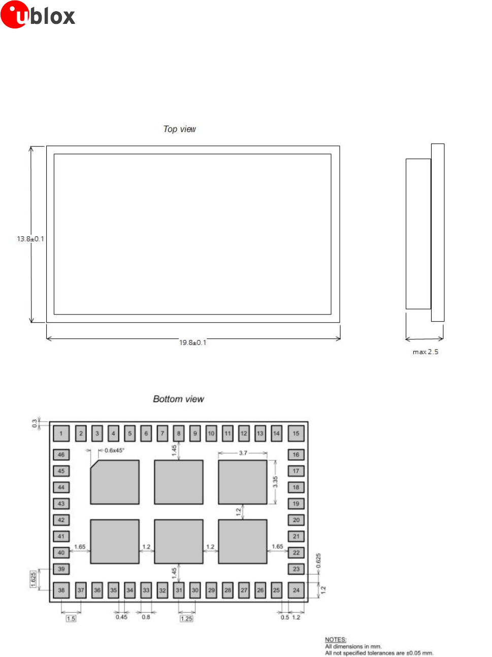
6 Mechanical specifications
Figure 12: Physical dimensions

EMMY-W1 series - User Manual
UBX-16015271 - R03 Product Information Qualification and approvals
Page 32 of 46
7 Qualification and approvals
7.1 Approvals
16
Products marked with this lead-free symbol on the product label comply with the
"Directive 2002/95/EC of the European Parliament and the Council on the Restriction of
Use of certain Hazardous Substances in Electrical and Electronic Equipment" (RoHS).
EMMY-W1 series Wi-Fi modules are RoHS compliant.
7.1.1 European Union regulatory compliance
The EMMY-W1 series module complies with the regulatory standards
Effective use of spectrum:
EN 300 328 V 1.8.1
EN 301 893 V 1.7.1
EMC:
EN 301 489-1/-17
Health and safety:
EN 60950-1:2006 + A11:2009
EN 62311 (WLAN)
EN 62479 (BT)
We declare that the human exposure of these modules is below the SAR limits specified in the EU
recommendations 1999/519/EC.
7.1.1.1 Equipment classes
A multi-radio module is classified as class-1 or class-2 radio equipment depending on the frequency band in
which it can operate. This equipment class is inherited by the end-product that integrates the module, thus it
must be marked accordingly.
Class-1 radio equipment can be placed on the market and put into service without restrictions.
(Article 1 of Commission Decision 2000/299/EC of April 6 2000)
This multi-radio module is defined as class-1 radio equipment when it is restricted to operate in the
following frequency bands:
Bluetooth , ISM band 2400 – 2483.5 MHz
WLAN, ISM band 2400 – 2483.5 MHz
WLAN, U-NII band-2e 5470 – 5725 MHz
Class-2 radio equipment includes restrictions applied by Member States as indicated in Article 1(2) of the
Commission Decision. This class uses the “Alert Sign” as an equipment class identifier.
Figure 13: Alert sign to identify equipment Class-2
16
These approvals are pending.
EMMY-W1 series - User Manual
UBX-16015271 - R03 Product Information Qualification and approvals
Page 33 of 46
If an end product allows the multiradio module to operate in the 5150-5350 MHz band (WLAN channel: 36-64),
it is defined as class-2 radio equipment and must be marked accordingly. Class-2 radio equipment must have the
"alert" sign affixed on the equipment, packaging and printed in the user manual.
The EMMY-W1 multiradio module uses harmonized frequency bands thus it is comprised by subclass H01 of
class 2 equipment, for which notification in accordance with article 6(4) of the R&TTE directive is not necessary.
A definition of subclasses of Class 2 equipment can be found in the following link:
http://ec.europa.eu/enterprise/sectors/rtte/files/rtte-subclass2_en.pdf
The table below shows the restrictions when operating WLAN at different bands within the European countries
Band
Channel number
Channel
frequency
[MHz]
Indoor use
allowed
Outdoor use
allowed
Radio
Equipment
Class
ISM
1 – 11
2412 – 2462
Yes
Yes
1
U-NII 1
36 – 48
5180 – 5240
Yes
No
2
U-NII 2
52 – 64
5260 – 5320
Yes
No
2
U-NII 2e
100 – 140
5500 – 5700
Yes
Yes
1
Table 33: Operating restrictions and radio equipment classification of EMMY-W1 series
Guidance on how the end product is marked in accordance with the R&TTE directive can be
found in the following links:
http://ec.europa.eu/enterprise/sectors/rtte/documents/index_en.htm - h2-5
http://ec.europa.eu/enterprise/sectors/rtte/documents/guidance/index_en.htm
A direct link to the quick guide to the marking requirements can be found here:
http://ec.europa.eu/enterprise/sectors/rtte/files/guidance/guidance_en.pdf
IMPORTANT: The ”CE” marking must be affixed to a visible location on the OEM product in
which this module is installed and has to be labeled in accordance to R&TTE Directive 1999/5/EC.
7.1.2 FCC compliance
The EMMY-W1 series module complies with Part 15 of the FCC Rules. Operation is subject to the following two
conditions:
1. This device may not cause harmful interference, and
2. This device must accept any interference received, including interference that may cause undesired
operation
Non authorized modification could void authority to use this equipment. The internal / external antenna(s) used
for this module must provide a separation distance of at least 20 cm from all persons and must not be
co-located or operating in conjunction with any other antenna or transmitter.
In accordance with 47 CFR § 15.19, the end product into which this module is integrated shall bear the
following statement in a conspicuous location on the device:
This device complies with Part 15 of the FCC Rules. Operation is subject to the following two conditions:
1. This device may not cause harmful interference, and
2. This device must accept any interference received, including interference that may cause undesired
operation

EMMY-W1 series - User Manual
UBX-16015271 - R03 Product Information Qualification and approvals
Page 34 of 46
When the end-product is so small or for such use that it is not practical to place the above statement on it, the
information shall be placed in a prominent location in the instruction manual or pamphlet supplied to the user or
on the container in which the device is marketed. However, the FCC ID label must be displayed on the device.
If the end-product will be installed in locations where the end-user is not able to see the FCC ID and/or this
statement, the FCC ID and the statement shall also be included in the end-product manual.
The outside of final products containing the EMMY-W1 module must display in a user accessible area a
label referring to the enclosed module. This exterior label can use wording such as the following:
“Contains Transmitter Module FCC ID: (XYZ)(UPN)” or “Contains FCC ID: (XYZ)(UPN)”, where (XYZ)
represents the FCC “Grantee Code” and (UPN) is the Unique Product Number decided by the grant
owner
17
.
7.1.3 IC compliance
The EMMY-W1 series module complies with Industry Canada license-exempt RSSs. Operation is subject to the
following two conditions:
(1) This device may not cause interference, and
(2) This device must accept any interference, including interference that may cause undesired operation of the
device.
Any notification to the end user of installation or removal instructions about the integrated radio module
is NOT allowed. Unauthorized modification could void authority to use this equipment.
This equipment complies with IC RSS-102 radiation exposure limits set forth for an uncontrolled environment.
This equipment should be installed and operated with minimum distance 20 cm between the radiator and your
body.
This radio transmitter IC: 8595A-EMMYW161, IC: 8595A-EMMYW163 and IC: 8595A-EMMYW165 has been
approved by Industry Canada to operate with the antenna types listed below with the maximum permissible gain
indicated. Antenna types not included in this list, having a gain greater than the maximum gain indicated for
that type, are strictly prohibited for use with this device.
Operation in the band 5150–5250 MHz is only for indoor use to reduce the potential for harmful
interference to co-channel mobile satellite systems;
Operation in the 5600-5650 MHz band is not allowed in Canada. High-power radars are allocated as
primary users (i.e. priority users) of the bands 5250-5350 MHz and 5650-5850 MHz and that these radars
could cause interference and/or damage to LE-LAN devices.
The Industry Canada certification label of a module shall be clearly visible at all times when installed in the host
device; otherwise, the host device must be labeled to display the Industry Canada certification number for the
module, preceded by the words “Contains transmitter module”, or the word “Contains”, or similar wording
expressing the same meaning, as follows: “Contains transmitter module IC: (CN)-(UPN)”, where (CN) is the
Company Number registered at Industry Canada and (UPN) is the Unique Product Number decided by the grant
owner.
Le présent appareil est conforme aux CNR d'Industrie Canada applicables aux appareils radio exempts de licence.
L'exploitation est autorisée aux deux conditions suivantes:
(1) l'appareil ne doit pas produire de brouillage, et
(2) l'utilisateur de l'appareil doit accepter tout brouillage radioélectrique subi, même si le brouillage est
susceptible d'en compromettre le fonctionnement.
Cet équipement est conforme aux limites d'exposition de rayonnement d'IC RSS-102 déterminées pour un
environnement non contrôlé. Cet équipement devrait être installé et actionné avec la distance minimum 20 cm
entre le radiateur et votre corps.
Cet émetteur radio, IC: 8595A-EMMYW161, IC: 8595A-EMMYW163 et IC: 8595A-EMMYW165 été approuvé
par Industry Canada pour fonctionner avec les types d’antenne énumérés ci-dessous avec le gain maximum
17
The FCC and IC IDs for the EMMY-W1 series module variants are shown in Table 37. Select the applicable ID.

EMMY-W1 series - User Manual
UBX-16015271 - R03 Product Information Qualification and approvals
Page 35 of 46
autorisé et l’impédance nécessaire pour chaque type d’antenne indiqué. Les types d’antenne ne figurant pas
dans cette liste et ayant un gain supérieur au gain maximum indiqué pour ce type-là sont strictement interdits
d’utilisation avec cet appareil.
Le dispositif de fonctionnement dans la bande 5150-5250 MHz est réservé à une utilisation en intérieur
pour réduire le risque d'interférences nuisibles à la co-canal systèmes mobiles par satellite
Opération dans la bande 5600-5650 MHz n'est pas autorisée au Canada. Haute puissance radars sont
désignés comme utilisateurs principaux (c.-àutilisateurs prioritaires) des bandes 5250-5350 MHz et 5650-
5850 MHz et que ces radars pourraient causer des interférences et / ou des dommages à dispositifs LAN-
EL.
L’étiquette d’homologation d’Industrie Canada d’un module donné doit être posée sur l’appareil hôte à un
endroit bien en vue en tout temps. En l’absence d’étiquette, l’appareil hôte doit porter une étiquette sur laquelle
figure le numéro d’homologation du module d’Industrie Canada, précédé des mots « Contient un module
d’émission », ou du mot « Contient », ou d’une formulation similaire allant dans le même sens et qui va comme
suit : « Contient le module d’émission IC: (CN)-(UPN) », où (CN) représente le numéro de compagnie, attribué
par Industrie Canada et (UPN) représente le numéro de produit unique attribué par le requérant.
The approval of the variant EMMY-W165 with the IC: 8595A-EMMYW165 is still in progress and
expected to be finished soon.
The internal / external antenna(s) used for this module must provide a separation distance of at least 20 cm from
all persons and must not be co-located or operating in conjunction with any other antenna or transmitter. See
Table 34 for list of approved antennas.
The approval type for all the EMMY-W1 series variants is a limited modular approval. Due to Industry
Canada Modular Approval Requirements (Source: RSP-100 Issue 10), any application which includes the
module must be approved by the module manufacturer (u-blox). The application manufacturer must
provide design data for the review procedure.
7.2 Approved antennas
For Bluetooth and Wi-Fi operation in the 2.4 GHz band and Wi-Fi operation in the 5 GHz band, the module has
been tested and approved for use with the antenna listed in Table 34.
Manufacturer
Part Number
Antenna type
Peak gain [dBi]
2.4 GHz band
5 GHz band
Antenova
A10194
SMD chip antenna 10x10x0.9 [mm] [4]
1.8
4.1
Linx
ANT-DB1-RAF-RPS
Dual-band dipole antenna [5]
2.5
4.6
Taoglas
GW.40.2153
Dual-band dipole antenna [6]
3.74
2.5
Taoglas
GW.59.3153
Dual-band dipole antenna [7]
2.37
2.93
Walsin
RFDPA870900SBLB8G1
Dual-band dipole antenna [8]
2
3
Linx
ANT-2.4-CW-RCT-RP
Single-band dipole antenna [9]
2.2
N/A
Delock
88395
Dual-band dipole antenna [10]
1.5
2.1
Table 34: List of approved dual-band antennas
The module can be integrated with other antennas which the OEM installer must authorize with respective
regulatory agencies and after approval of the module manufacturer.

EMMY-W1 series - User Manual
UBX-16015271 - R03 Product Information Qualification and approvals
Page 36 of 46
7.2.1 Bluetooth antenna
The following antennas are designated for Bluetooth transmission on EMMY-W163:
Manufacturer
Part Number
Antenna type
Peak gain [dBi]
2.4 GHz band
Johanson
Technology
2450AT45A100
SMD chip antenna 10x10x0.9 [mm] [11]
2.2
Taoglas
GW.26.0151
Single-band monopole antenna [12]
0.0
Linx
ANT-2.4-CW-RH
Single-band monopole antenna [13]
-0.9
Table 35: List of approved single-band antennas
7.2.2 NFC antenna
The following antennas are designated to be used for Near Field Communication (NFC) on EMMY-W161,
EMMY-W163 and EMMY-W165:
Manufacturer
Part Number
Antenna type
u-blox
EMMY_NFC_ANT
External PCB antenna with connector
Table 36: List of approved NFC antenna
7.3 FCC and IC IDs (planned)
Product name
FCC ID
IC ID
EMMY-W161
XPYEMMYW161
8595A-EMMYW161
EMMY-W161-A
XPYEMMYW161
8595A-EMMYW161
EMMY-W163
XPYEMMYW163
8595A-EMMYW163
EMMY-W163-A
XPYEMMYW163
8595A-EMMYW163
EMMY-W165
XPYEMMYW165
8595A-EMMYW165
EMMY-W165-A
XPYEMMYW165
8595A-EMMYW165
Table 37: FCC and IC IDs for different models of EMMY-W1 series
7.4 Certification in other countries
Regulatory approvals for using the EMMY-W1 series module in Japan, South Korea, China, Taiwan and Australia
are pending.
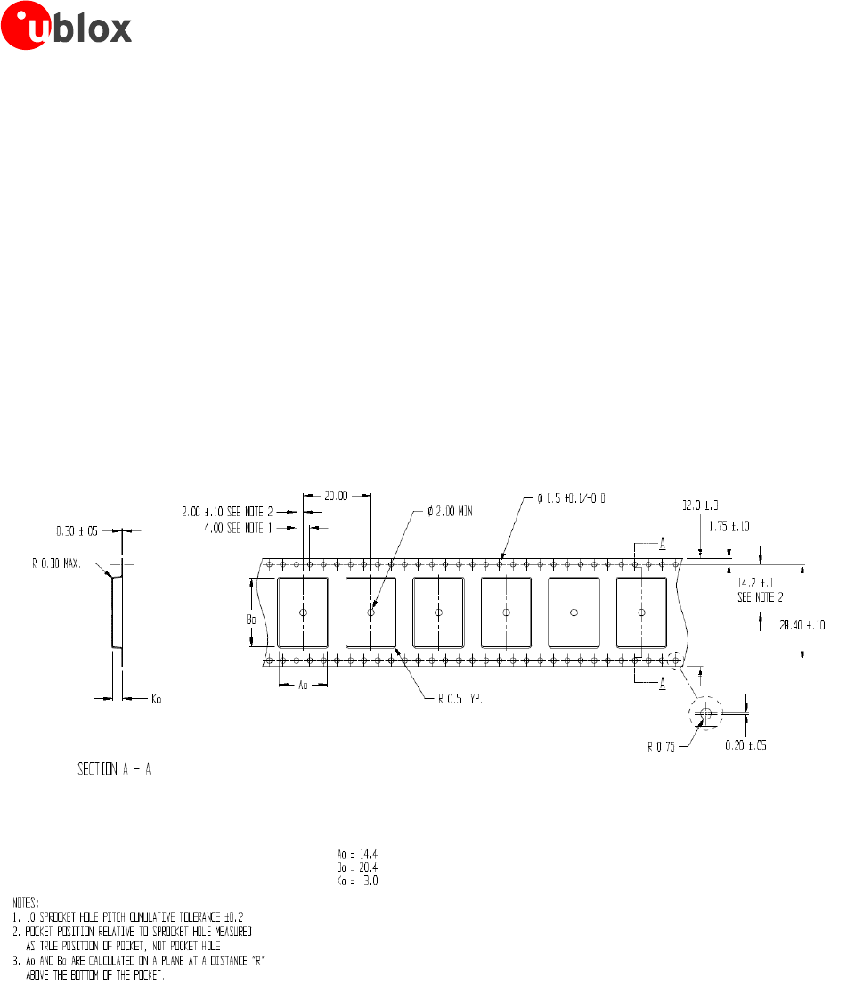
EMMY-W1 series - User Manual
UBX-16015271 - R03 Product Information Product handling
Page 37 of 46
8 Product handling
8.1 Packaging
The EMMY-W1 series modules are delivered as hermetically sealed tape and reels, to enable efficient production,
production lot set-up and tear-down. For more information about packaging, see the u-blox Package
Information Guide [1].
8.1.1 Reels
The EMMY-W1 series modules are deliverable in quantities of 500 pieces on a reel. The EMMY-W1 series
modules are shipped on reel Type A as described in the u-blox Package Information Guide [1].
8.1.2 Tapes
The dimensions of the tapes are specified in Figure 14.
Figure 14: EMMY-W1 Tape dimensions
8.2 Shipment, storage and handling
For more information regarding shipment, storage and handling see the u-blox Package Information Guide [1].
8.2.1 Moisture sensitivity levels
The EMMY-W1 series modules are rated at moisture sensitivity level 3. See moisture sensitive warning label on
each shipping bag for detailed information. After opening the dry pack, modules must be mounted within 168
hours in factory conditions of maximum 30°C/60%RH or must be stored at less than 10%RH. Modules require
baking if the humidity indicator card shows more than 10% when read at 23±5°C or if the conditions
mentioned above are not met. Please refer to J-STD-033B standard for bake procedure. }
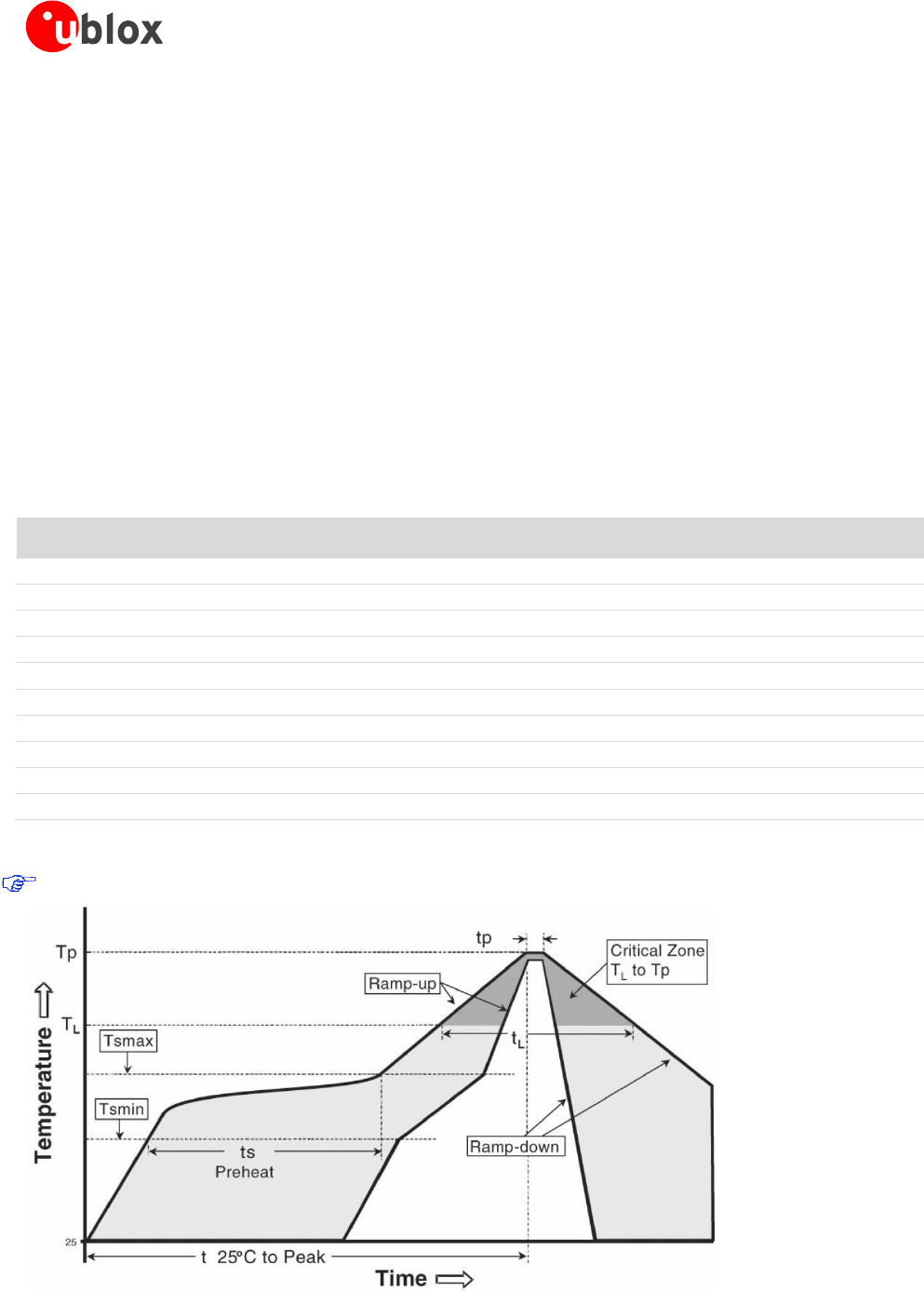
EMMY-W1 series - User Manual
UBX-16015271 - R03 Product Information Product handling
Page 38 of 46
8.2.2 Mounting process and soldering recommendations
The EMMY-W1 series module is a surface mount module supplied on a 4-layer FR4-type PCB with gold plated
connection pins and produced in a lead-free process with a lead-free soldering paste. The wrap page of the PCB
is max. 0,75% according to IPC-A-610E. The thickness of solder resist on the host PCB top side and the
EMMY-W1 bottom side must be considered for the soldering process.
This module is compatible with industrial reflow profile for RoHS/Pb-free solders, Sn96.5/Ag3.0/Cu0.5 solder is a
right choice. Use of "No Clean" soldering paste is strongly recommended, cleaning the populated modules is
strongly discouraged - residuals under the module cannot be easily removed with any cleaning process. Cleaning
with water can lead to capillary effects where water is absorbed into the gap between the host board and
module. The combination of soldering flux residuals and encapsulated water could lead to short circuits between
neighboring pins.
Only a single reflow soldering process is permitted for host boards with the EMMY-W1 series modules.
The reflow profile used is dependent on the thermal mass of the entire populated PCB, heat transfer efficiency
of the oven and particular type of solder paste used. Since the profile used is process and layout dependent, the
optimum profile should be studied case by case. Recommendations below should be taken as a starting point
guide. In case of basic information necessity, please refer to J-STD-020C standard. }
Profile feature
Sn-Pb eutectic
(Sn63/Pb37)
RoHS/Pb-free
(Sn96.5/Ag3.0/Cu0.5)
Ramp up rate (TSMAX to TP)
3 °C/sec max
3 °C/sec max
Minimum soak temperature (TSMIN)
100 °C
150 °C
Maximum soak temperature (TSMAX)
150 °C
200 °C
Soak time (ts)
60 - 120 sec
60 - 180 sec
Liquidus temperature (TL)
183 °C
217 °C
Time above TL (tL)
60 - 150 sec
60 - 150 sec
Peak temperature (TP)
215 – 225 °C
235 – 245 °C
Time within +0 / -5°C of actual TP (tp)
10 - 30 sec
20 - 40 sec
Ramp down rate
6 °C/sec max
6 °C/sec max
Time from 25°C to TP
6 min max
8 min max
Table 38: Recommended reflow profile
The lowest value of TP and slower ramp down rate (2 – 3 °C/sec) is preferred.
Figure 15: Reflow profile
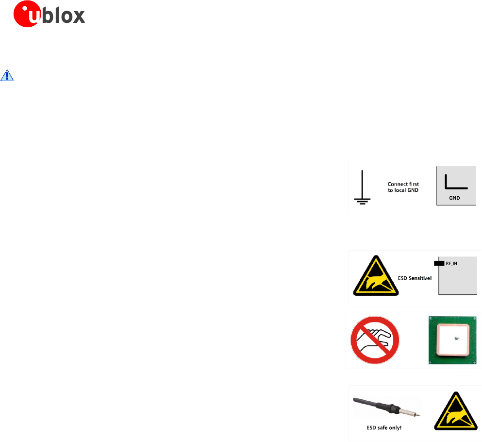
EMMY-W1 series - User Manual
UBX-16015271 - R03 Product Information Product handling
Page 39 of 46
8.2.3 ESD handling precautions
EMMY-W1 series modules are Electrostatic Sensitive Devices (ESD). Observe precautions for
handling! Failure to observe these precautions can result in severe damage to the Wi-Fi receiver!
Wi-Fi transceivers are Electrostatic Sensitive Devices (ESD) and require special precautions when handling.
Particular care must be exercised when handling patch antennas, due to the risk of electrostatic charges. In
addition to standard ESD safety practices, the following measures should be taken into account whenever
handling the receiver:
Unless there is a galvanic coupling between the
local GND (i.e. the work table) and the PCB GND,
then the first point of contact when handling the
PCB must always be between the local GND and
PCB GND.
Before mounting an antenna patch, connect
ground of the device
When handling the RF pin, do not come into
contact with any charged capacitors and be
careful when contacting materials that can
develop charges (e.g. patch antenna ~10 pF, coax
cable ~50-80 pF/m, soldering iron, …)
To prevent electrostatic discharge through the RF
input, do not touch any exposed antenna area. If
there is any risk that such exposed antenna area is
touched in non ESD protected work area,
implement proper ESD protection measures in the
design.
When soldering RF connectors and patch
antennas to the receiver’s RF pin, make sure to
use an ESD safe soldering iron (tip).
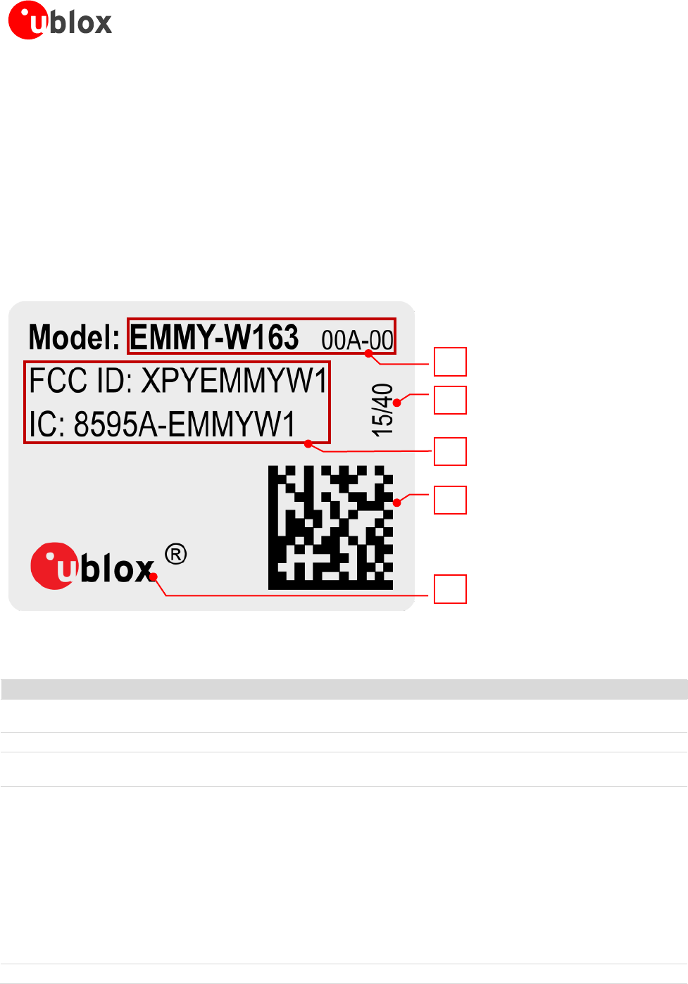
EMMY-W1 series - User Manual
UBX-16015271 - R03 Product Information Labeling and ordering information
Page 40 of 46
9 Labeling and ordering information
9.1 Product labeling
The labels of EMMY-W1 series include important product information as described in this section. The data
matrix code for automotive and professional grade variants of EMMY-W1 series includes a serial number.
Figure 16 illustrates the sample label of the automotive grade (professional grade is similar and differs with
respect to product version (1) as mentioned in Table 39) of the EMMY-W1 series and includes: the u-blox logo,
product name (model), type number, FCC and IC certification number and date of unit production encoded
YY/WW (year/week).
Figure 16: EMMY-W1 series – Professional grade sample label
A detailed description of the label components are listed in Table 39. The first three digits of the serial number
represent the Bluetooth MAC address.
Reference
Description
1
Text “MODEL:” followed by product type number, omitting the second dash and smaller font used for the product
version identifier (“xxB-yy” for professional and “xxA-yy” for automotive grade).
2
Date of production encoded YY/WW (year/week)
3
FCC/IC ID which the module has been listed with
4
Data Matrix with unique serial number of 15 alphanumeric symbols.
The 3 first symbols represent the unique module type no:
631: EMMY-W161-00A-00,
632: EMMY-W163-00A-00,
700: EMMY-W163-00B-00,
701: EMMY-W161-00B-00,
756: EMMY-W165-00A-00,
???: EMMY-W165-00B-00,
, the next 8 symbols represent the unique hexadecimal Bluetooth MAC address (see section 1.7 for more information
about MAC addresses) of the module AABBCCDDEE, and the last 4 symbols represent the hardware and firmware
version encoded HHFF.
5
u-blox logo, the red dot in the logo is also marking pin no 1
Table 39 EMMY-W1 series label description
5
3
4
2
1

EMMY-W1 series - User Manual
UBX-16015271 - R03 Product Information Labeling and ordering information
Page 41 of 46
9.2 Explanation of codes
Two different product code formats are used. The Product Name is used in documentation such as this data
sheet and identifies all u-blox products, independent of packaging and quality grade. The Ordering Code
includes options and quality, while the Type Number includes the hardware and firmware versions. Table 40
below details these three different formats:
Format
Structure
Product Name
PPPP-TGVV
Ordering Code
PPPP-TGVV-TTQ
Type Number
PPPP-TGVV-TTQ-XX
Table 40: Product code formats
Table 41 explains the parts of the product code.
Code
Meaning
Example
PPPP
Form factor
EMMY
TG
Platform
T – Dominant technology, For example, W: Wi-Fi, B: Bluetooth
G - Generation
W1
VV
Variant based on the same platform; range [00…99]
61
TT
Major Product Version
00
Q
Quality grade
A: Automotive
B: Professional
C: Standard
A
XX
Minor product version (not relevant for certification)
00
Table 41: Part identification code
9.3 Ordering codes
Ordering Code
Product name
Product
EMMY-W161-00B
EMMY-W161
EMMY-W161 professional grade module
EMMY-W161-00A
EMMY-W161-A
EMMY-W161 automotive grade module
EMMY-W163-00B
EMMY-W163
EMMY-W163 professional grade module
EMMY-W163-00A
EMMY-W163-A
EMMY-W163 automotive grade module
EMMY-W165-00B
EMMY-W165
EMMY-W165 professional grade module
EMMY-W165-00A
EMMY-W165-A
EMMY-W165 automotive grade module
EVK-EMMY-W161-A
EVK-EMMY-W161
Evaluation kit for EMMY-W161 and EMMY-W161-A
EVK-EMMY-W163-A
EVK-EMMY-W163
Evaluation kit for EMMY-W163 and EMMY-W163-A
Table 42: Product ordering codes
Product changes affecting form, fit or function are documented by u-blox. For a list of Product Change
Notifications (PCNs) see our website.

EMMY-W1 series - User Manual
UBX-16015271 - R03 Product Information Appendix
Page 42 of 46
Appendix
A Glossary
Name
Definition
ACL
Access control list
AES
Advanced Encryption Standard
BPF
Band-Pass Filter
BT
Bluetooth
BAW
Bulk Acoustic Wave
CPU
Central Processing Unit
DTIM
Delivery traffic indication message
DC
Direct Current
DDR
Double Data Rate
ESD
Electrostatic Sensitive Devices
EMV
Europay, MasterCard and Visa
FCC
Federal Communications Commission
FIFO
First In, First Out
GI
Guard interval
GND
Ground
GPIO
General-purpose input/output
HD
High Definition
HCI
Host Controller Interface
IC
Industry Canada
IMDS
International Material Data System
IMEI
International Mobile Station Equipment Identity
LED
Light-emitting diode
LTE
Long Term Evolution
LE
Low Energy
MAC
Medium Access Control
MWS
Mobile Wireless Standards
MCS
Modulation Coding Scheme
MSL
Moisture sensitivity level
NFC
Near-Field Communication
NFCIP
NFC Interface and Protocol
OEM
Original equipment manufacturer
P2P
Peer-to-peer
PCB
Printed Circuit Board
PCN
Product Change Notification
PCM
Pulse-code modulation
R&TTE
Radio and telecommunications terminal equipment
RF
Radio Frequency
RSS
Radio Standards Specification
RH
Relative humidity
RoHS
Restriction of Hazardous Substances
SDIO
Secure Digital Input Output

EMMY-W1 series - User Manual
UBX-16015271 - R03 Product Information Appendix
Page 43 of 46
Name
Definition
SDR
Secure Digital Rate
SMD
Surface-mount Device
SCO
Synchronous Connection-Oriented
UART
Universal Asynchronous Receiver/Transmitter
Table 43: Explanation of abbreviations and terms used

EMMY-W1 series - User Manual
UBX-16015271 - R03 Product Information Related documents
Page 44 of 46
Related documents
[1] u-blox Package Information Guide, document number UBX-14001652
[2] Driver Software Application Note for ELLA-W1 series and EMMY-W1 series, document number
UBX-15012542
[3] EMMY-W1 series System Integration Manual, document number UBX-15024929
[4] Mixtus A10194 Product Specification, Antenova-M2M, http://www.antenova-
m2m.com/documents/download/40c67cf2e7a4c7b8cd0f7faed7f6d2ca4fe1886d597d5, October 2015
[5] ANT-DB1-RAF-xxx Data Sheet, Linx, http://www.linxtechnologies.com/resources/data-guides/ant-db1-
raf-xxx.pdf, October 2015
[6] Specification. Part No.: GW.40.2153, taoglas, https://fccid.io/pdf.php?id=2415249, December 2015
[7] Specification. Part No.: GW.59.3153, taoglas,
http://www.taoglas.com/images/product_images/original_images/GW.59.3153- 2.4GHz-5.8GHz Band
Mount Dipole Antenna 080910.pdf, October 2015
[8] 2015 RF Devices and High Frequency Inductors Product catalog,
http://www.passivecomponent.com/document/HF_Devices/2013RF_Catalogue.pdf, December 2015
[9] ANT-2.4-CW-RCT-xx Data Sheet, Linx, http://www.linxtechnologies.com/resources/data-guides/ant-
2.4-cw-rct-xx.pdf, October 2015
[10] Delock WLAN 802.11 ac/a/b/g/n Antenna RP-SMA 2 dBi Omnidirectional Joint, 2015-11-26
http://www.delock.com/produkt/88395/pdf.html?sprache=en, November 2015
[11] 2.45 GHz High Gain SMD Chip Antenna P/N 2450AT45A100, Johanson Technology,
http://www.johansontechnology.com/datasheets/antennas/2450AT45A100.pdf, October 2015
[12] 2.4 GHz Miniature Screw mount Monopole Antenna, taoglas,
http://www.taoglas.com/images/product_images/original_images/GW.26.0112 2.4GHz Band
Monopole SMA%28M%29RA.pdf, December 2015
[13] ANT-2.4-CW-RH Data Sheet, Linx, http://www.linxtechnologies.com/resources/data-guides/ant-2.4-cw-
rh-xxx.pdf, December 2015
For regular updates to u-blox documentation and to receive product change notifications, register on our
homepage (http://www.u-blox.ch/).

EMMY-W1 series - User Manual
UBX-16015271 - R03 Product Information Revision history
Page 45 of 46
Revision history
Revision
Date
Name
Status / Comments
R01
23-June-2016
Daniel Dietterle
Draft
R02
01-July-2016
Daniel Dietterle
Document release after review
R03
05-July-2016
Daniel Dietterle
Corrected maximum output power for EMMY-W163 in Table 26 and Table 27

EMMY-W1 series - User Manual
UBX-16015271 - R03 Product Information Contact
Page 46 of 46
Contact
For complete contact information visit us at www.u-blox.com
u-blox Offices
North, Central and South America
u-blox America, Inc.
Phone: +1 703 483 3180
E-mail: info_us@u-blox.com
Regional Office West Coast:
Phone: +1 408 573 3640
E-mail: info_us@u-blox.com
Technical Support:
Phone: +1 703 483 3185
E-mail: support@u-blox.com
Headquarters
Europe, Middle East, Africa
u-blox AG
Phone: +41 44 722 74 44
E-mail: info@u-blox.com
Support: support@u-blox.com
Asia, Australia, Pacific
u-blox Singapore Pte. Ltd.
Phone: +65 6734 3811
E-mail: info_ap@u-blox.com
Support: support_ap@u-blox.com
Regional Office Australia:
Phone: +61 2 8448 2016
E-mail: info_anz@u-blox.com
Support: support_ap@u-blox.com
Regional Office China (Beijing):
Phone: +86 10 68 133 545
E-mail: info_cn@u-blox.com
Support: support_cn@u-blox.com
Regional Office China (Shenzhen):
Phone: +86 755 8627 1083
E-mail: info_cn@u-blox.com
Support: support_cn@u-blox.com
Regional Office India:
Phone: +91 959 1302 450
E-mail: info_in@u-blox.com
Support: support_in@u-blox.com
Regional Office Japan:
Phone: +81 3 5775 3850
E-mail: info_jp@u-blox.com
Support: support_jp@u-blox.com
Regional Office Korea:
Phone: +82 2 542 0861
E-mail: info_kr@u-blox.com
Support: support_kr@u-blox.com
Regional Office Taiwan:
Phone: +886 2 2657 1090
E-mail: info_tw@u-blox.com
Support: support_tw@u-blox.com