Wedge it com HHR1 AP router User Manual
Wedge-it.com Ltd AP router Users Manual
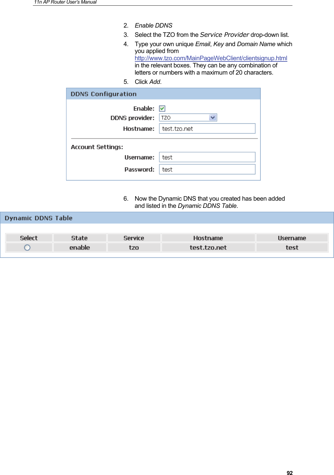
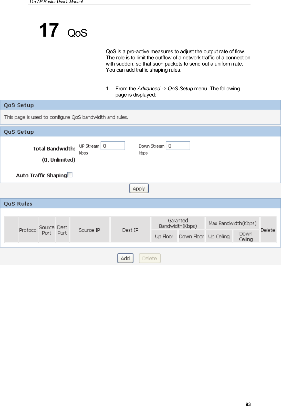
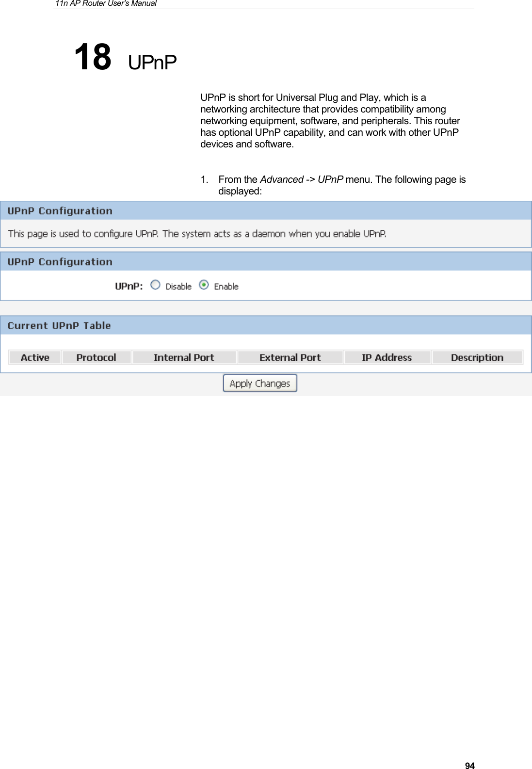
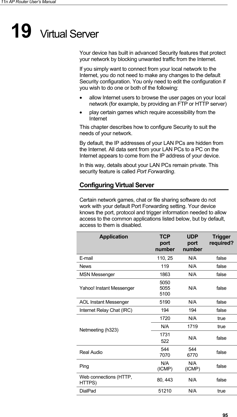
UserManual.wiki
>
Wedge it com
>
HHR1 User Manual
Users Manual
Navigation menu
Upload a User Manual
Namespaces
Wiki Guide
HTML
PDF
Info
Views
User Manual
Discussion / Help
Navigation

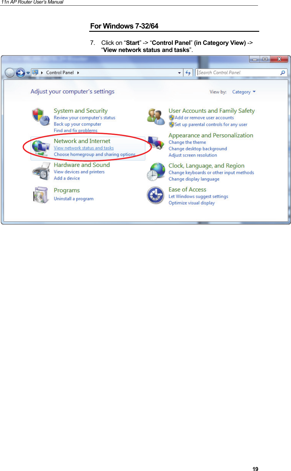
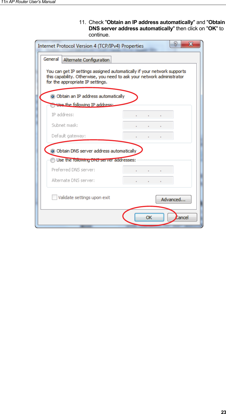
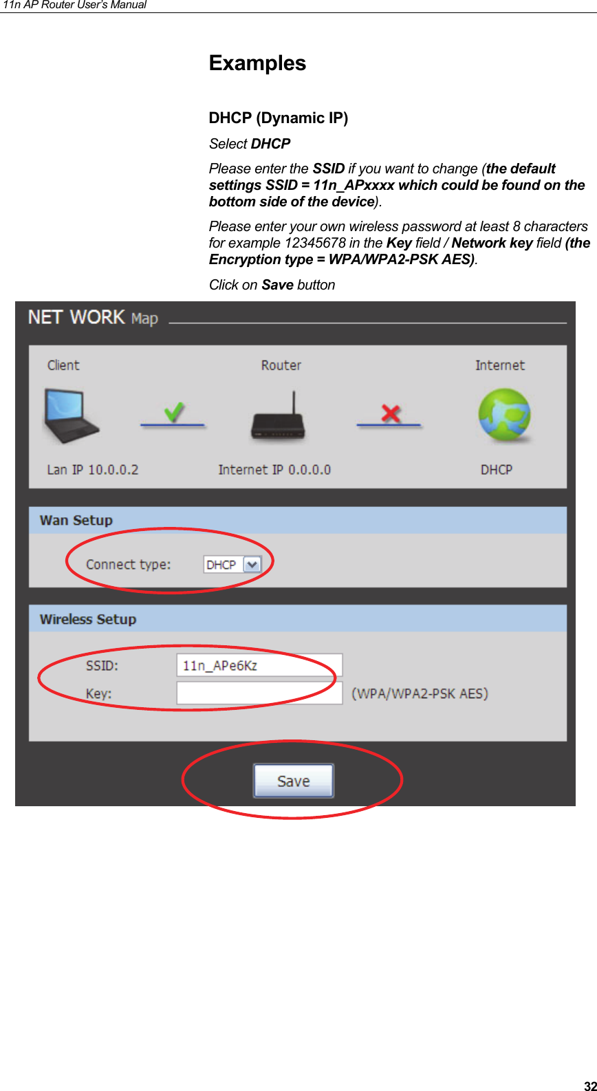
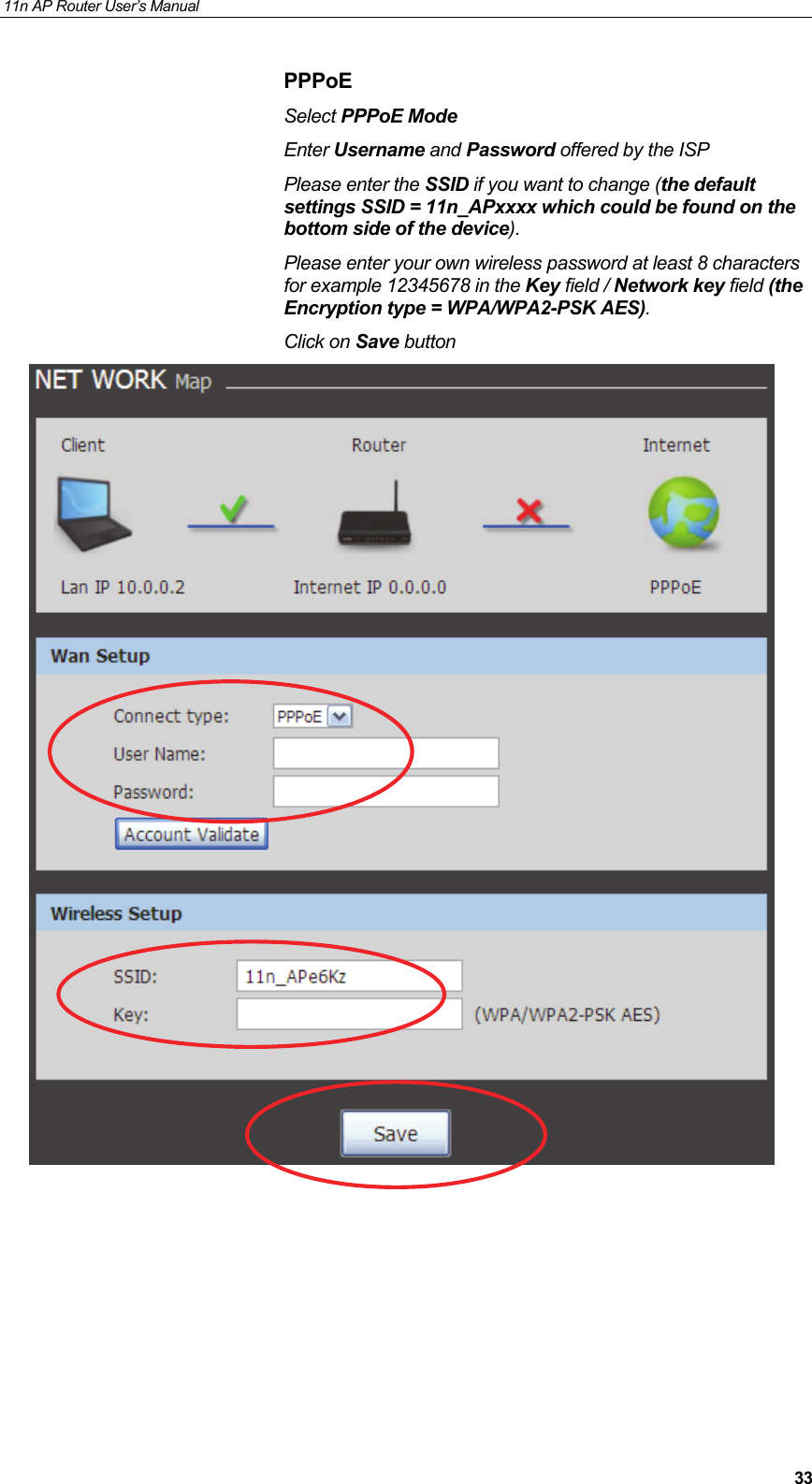
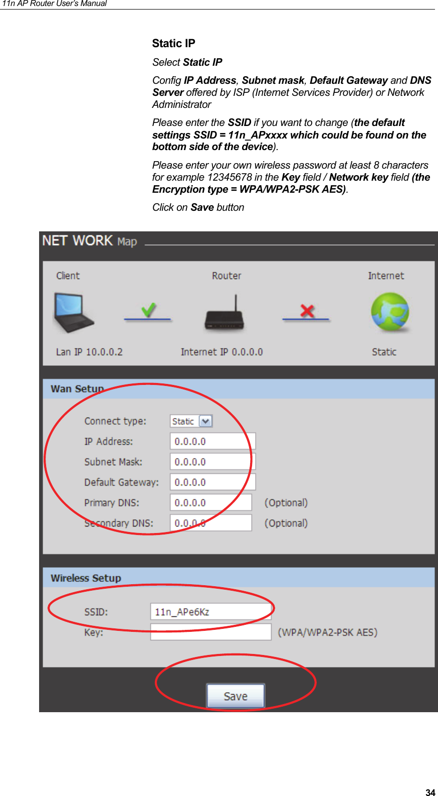
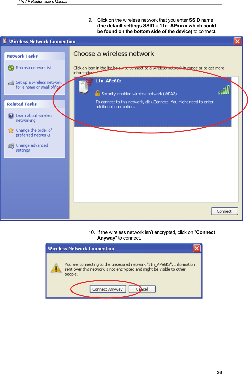
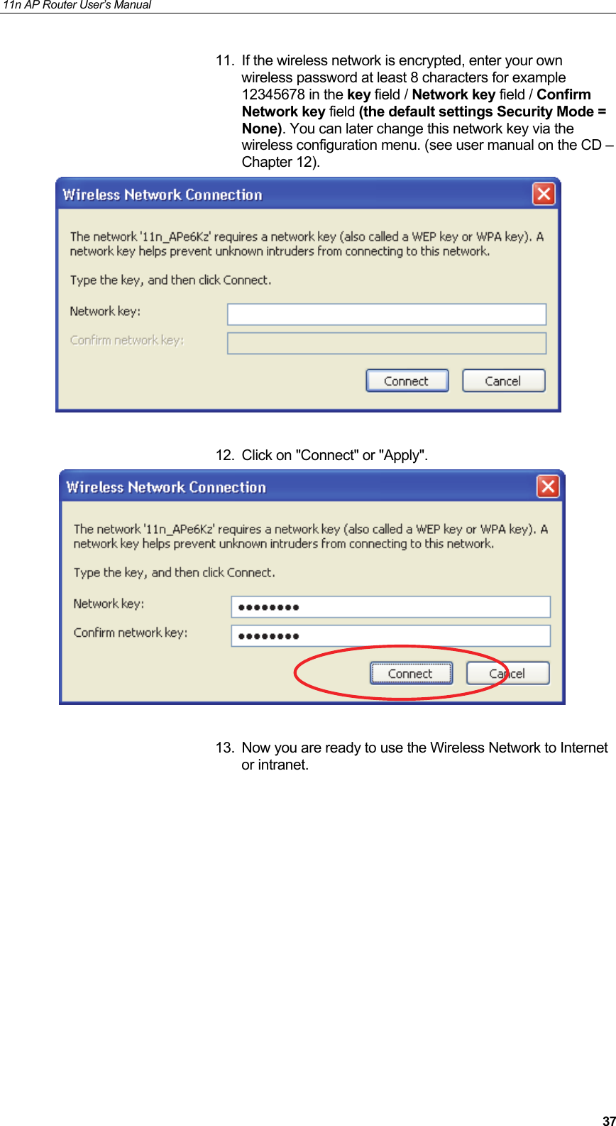
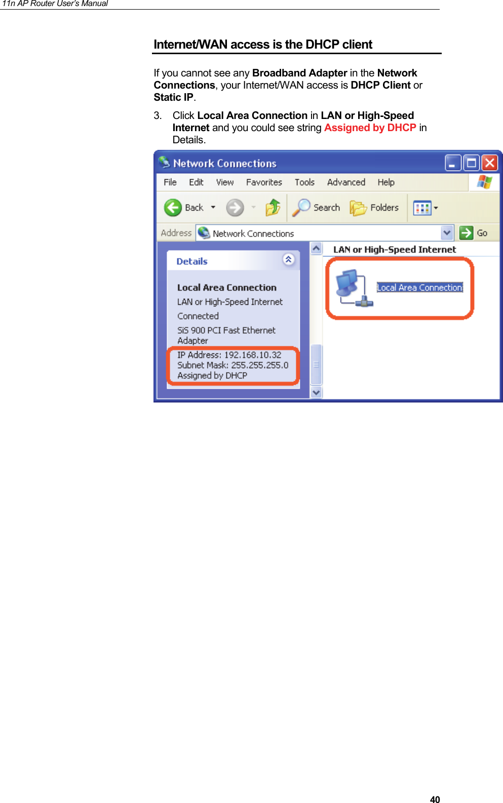
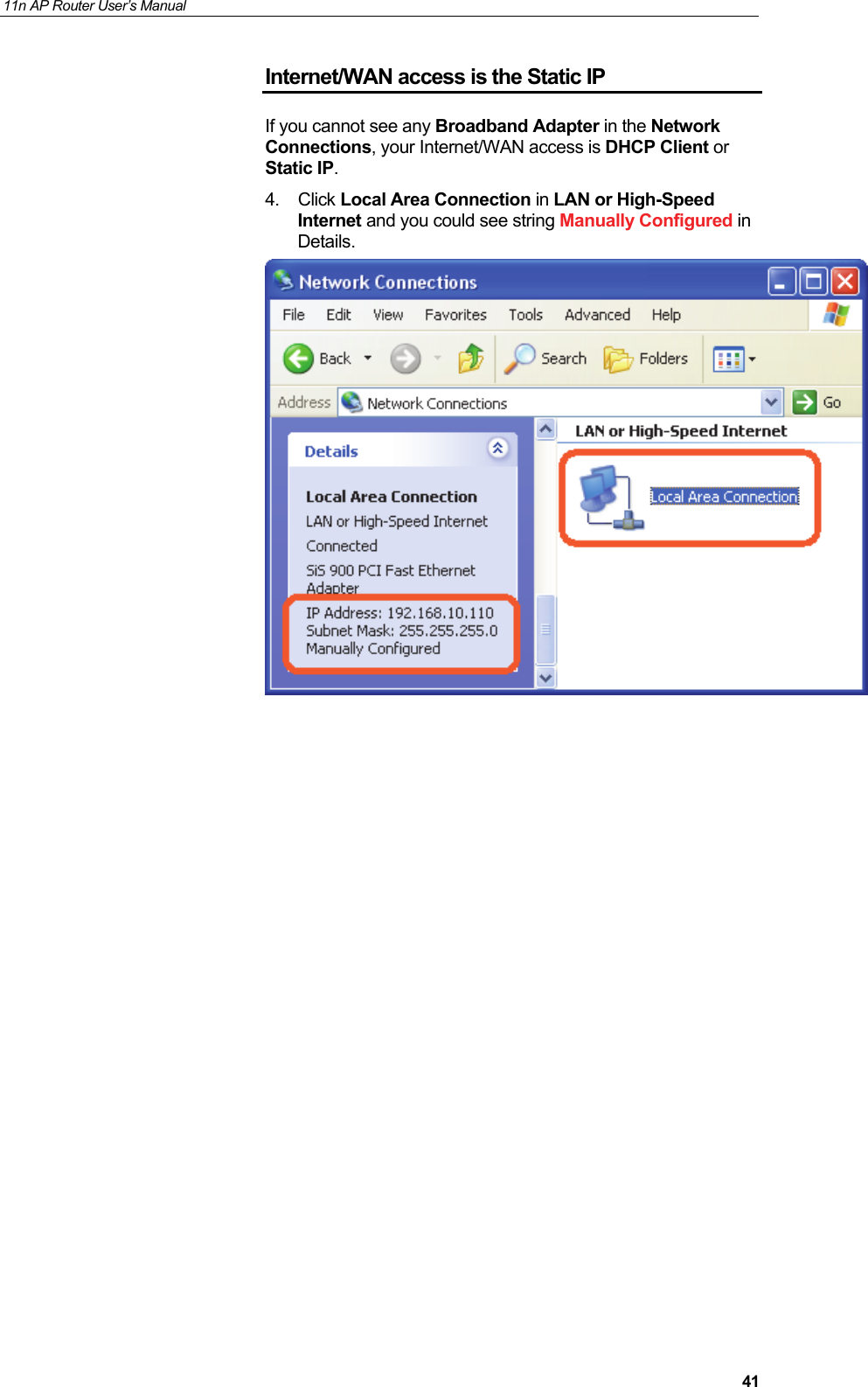
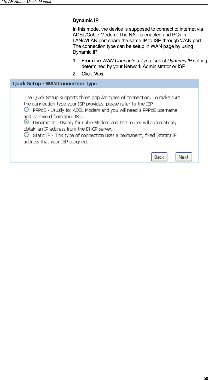
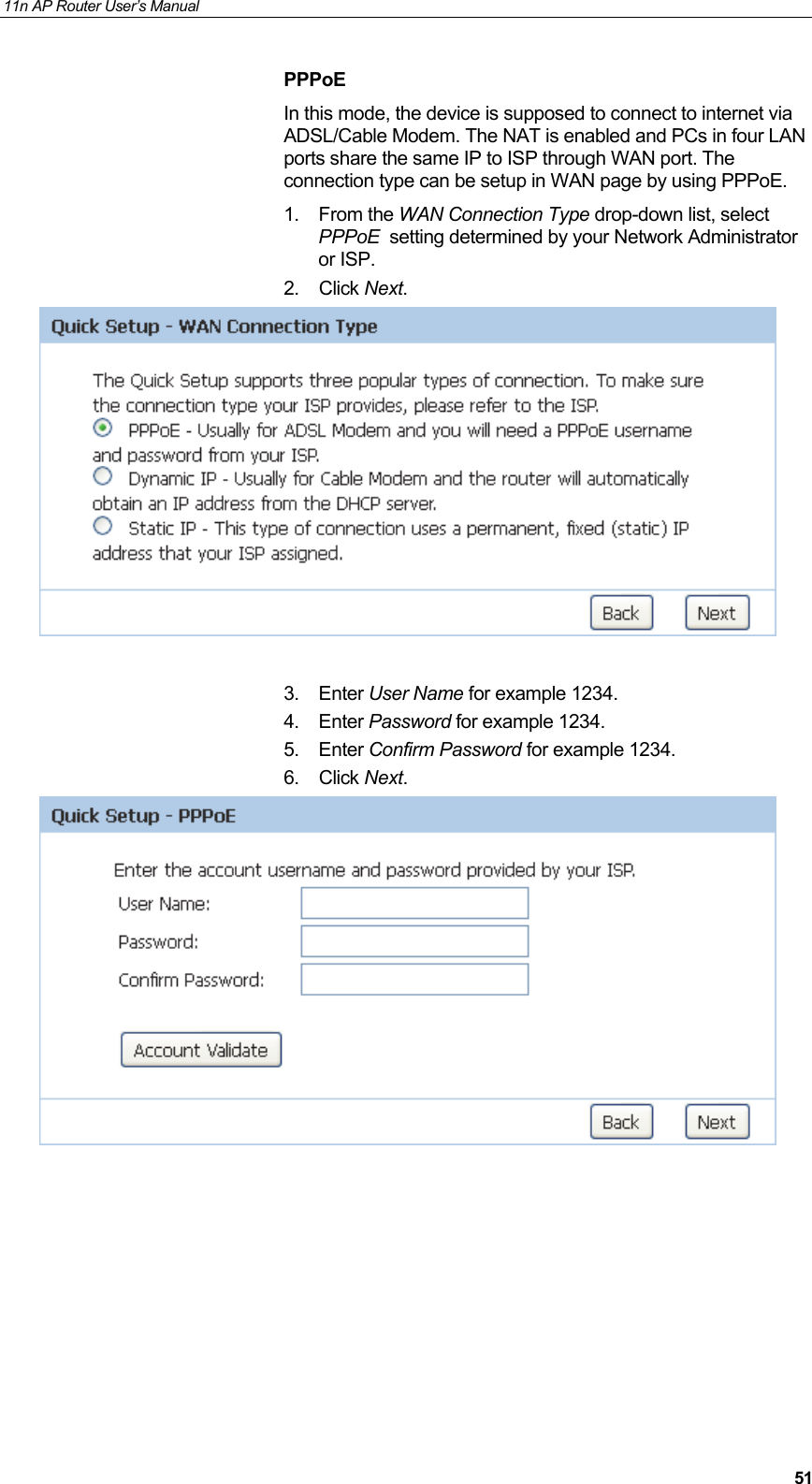
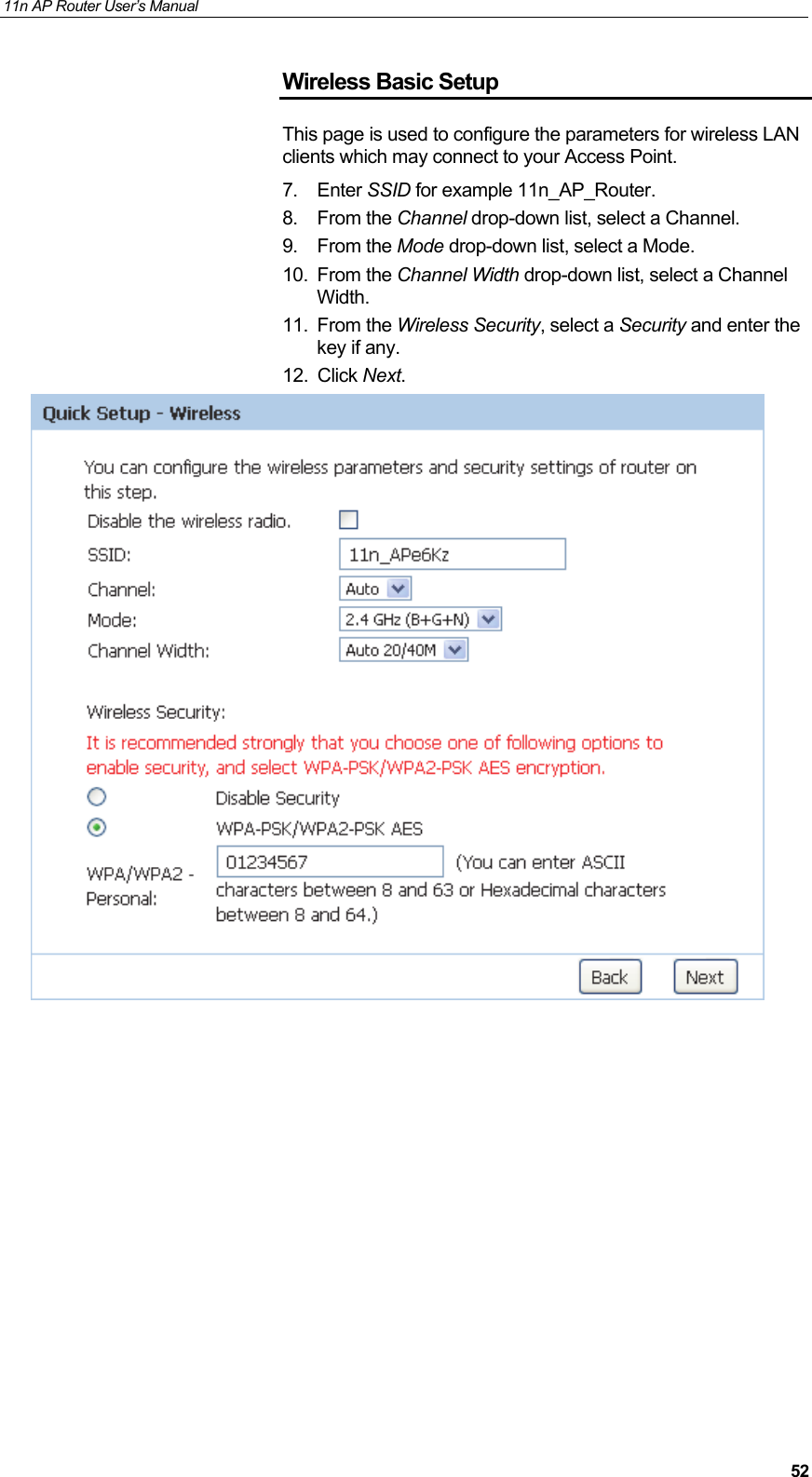
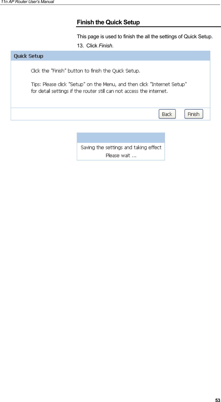
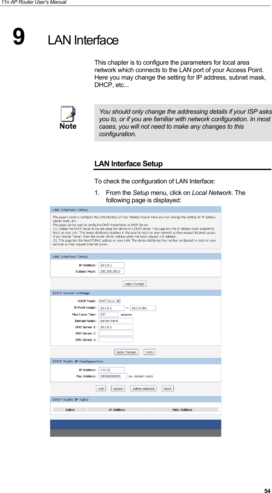
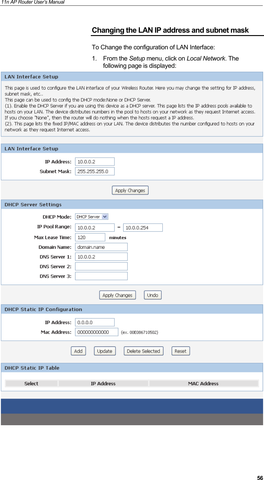
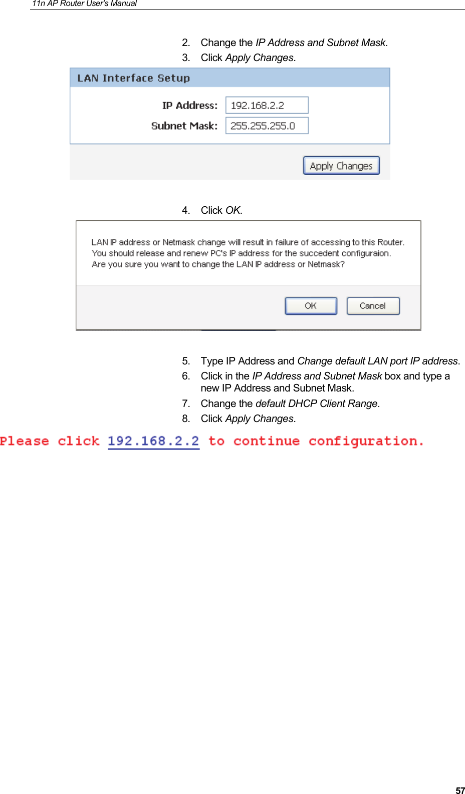
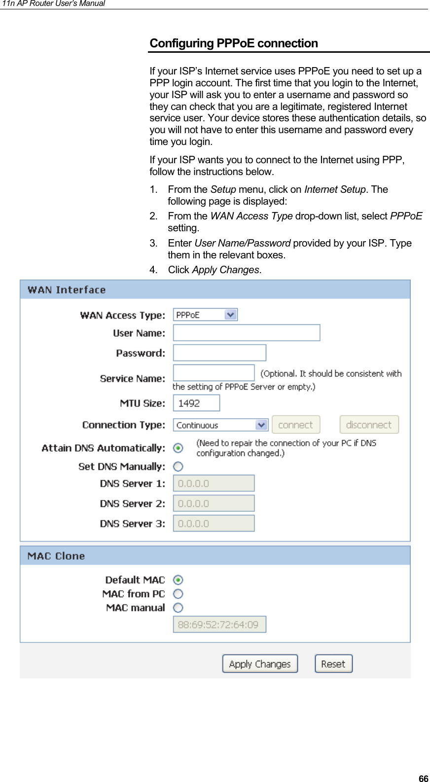
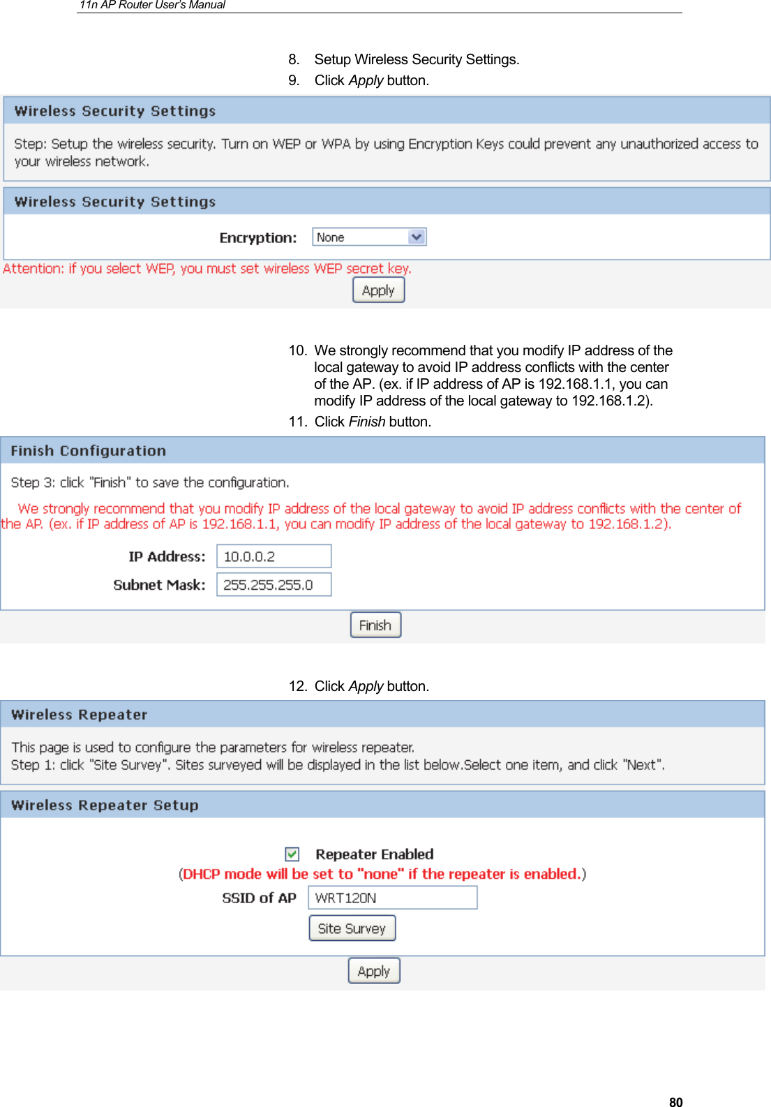
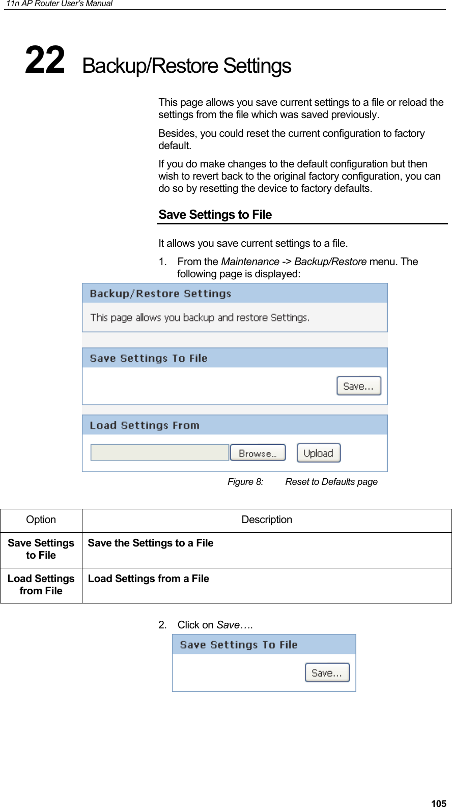
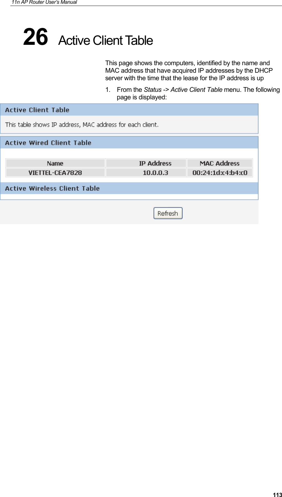
![11n AP Router User’s Manual 315 Advanced Configuration Advanced Configuration with Router Mode 1. From any of the LAN computers connected to , launch your web browser, type the following URL in the web address (or location) box, and press [Enter] on your keyboard: http://10.0.0.2 2. Select the Connect type DHCP, Static or PPPoE and enter related parameters that your ISP (Internet Services Provider) or Network Administrator provided. 3. Please enter the “SSID” if you want to change (the default settings SSID = 11n_APxxxx which could be found on the bottom side of the device). 4. Please enter your own wireless password at least 8 characters for example 12345678 in the Key field / Network key field (the Encryption type = WPA/WPA2-PSK AES). 5. Click on “Save” button.](https://usermanual.wiki/Wedge-it-com/HHR1/User-Guide-2447222-Page-31.png)
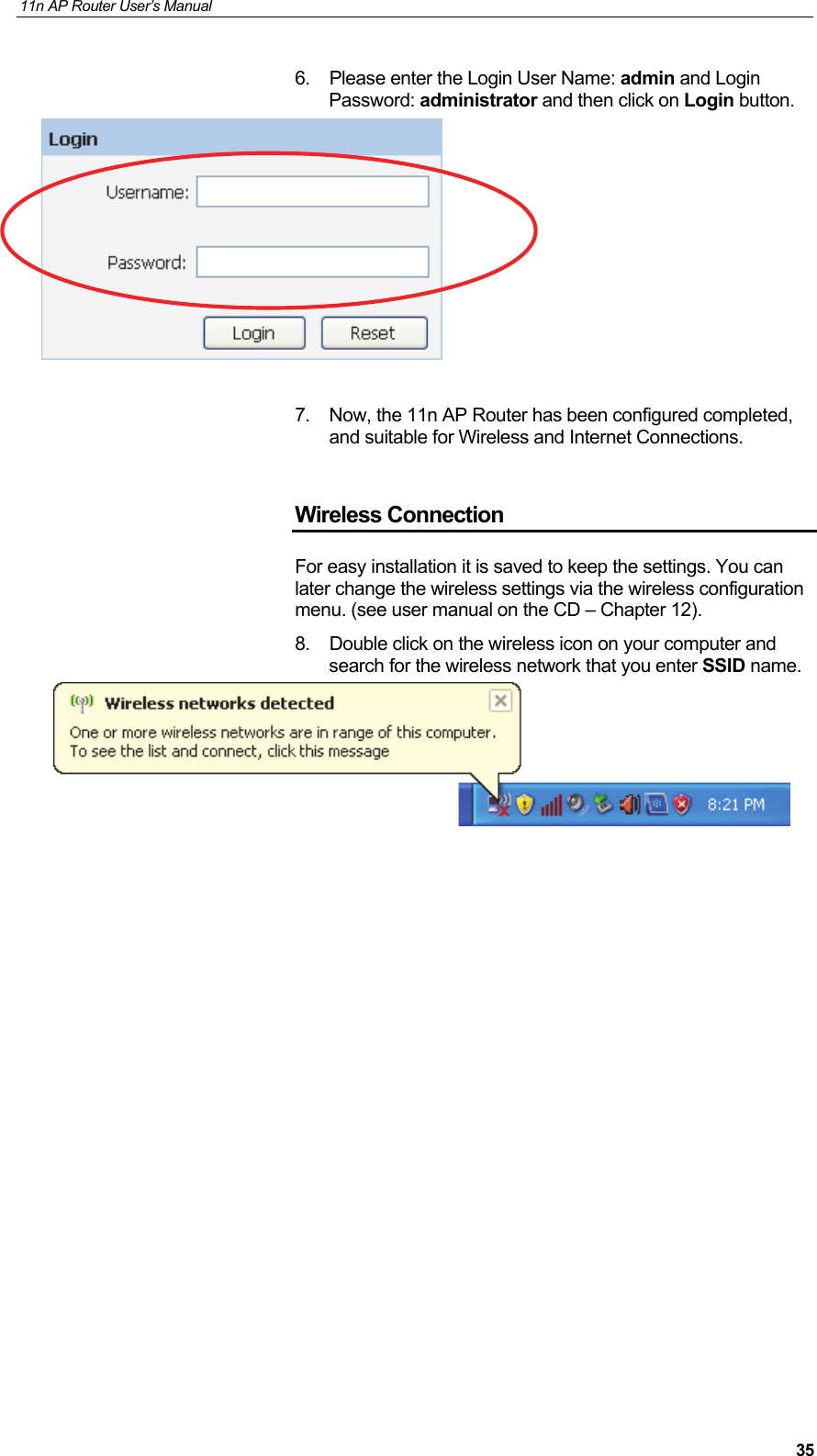

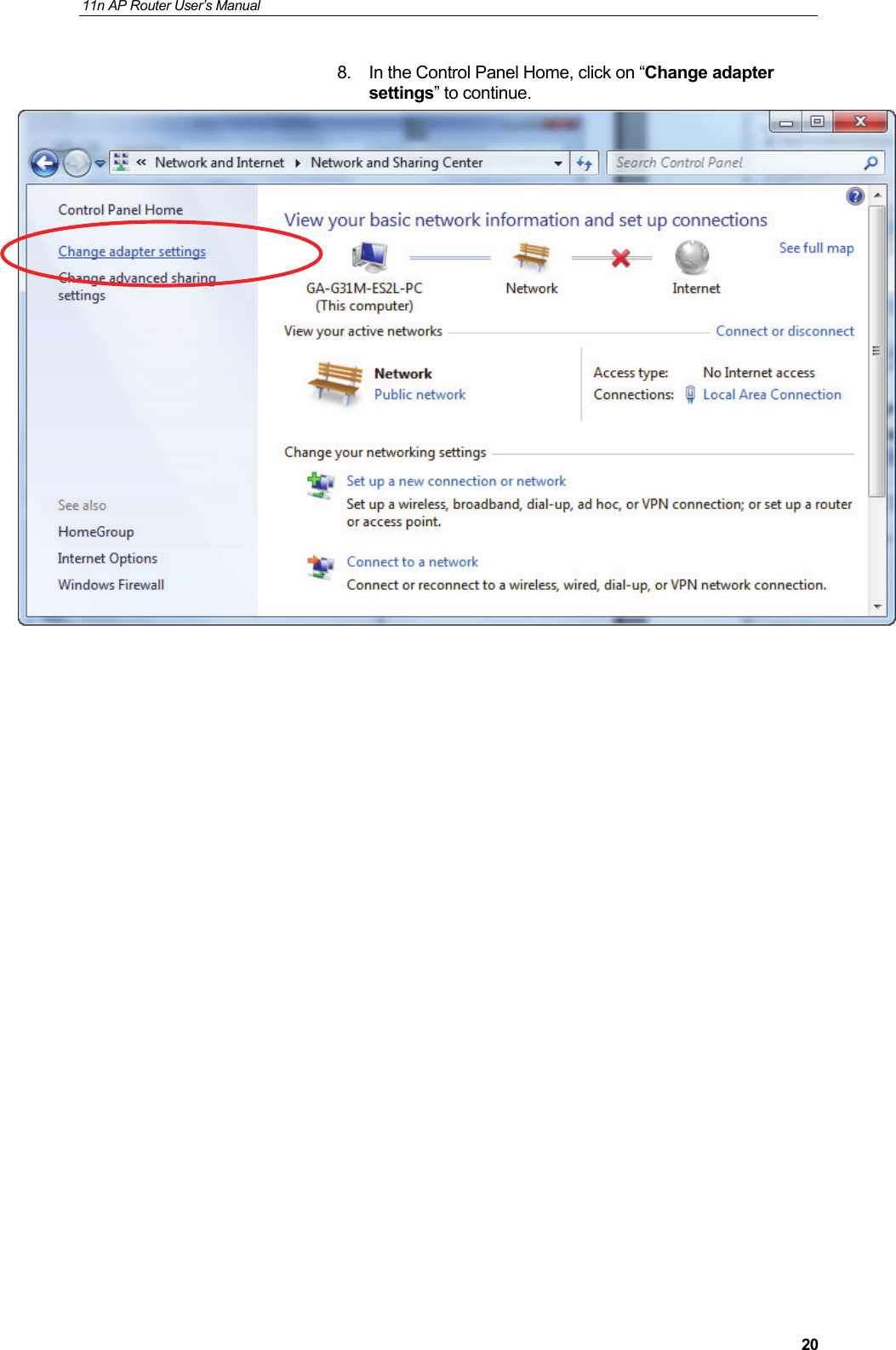
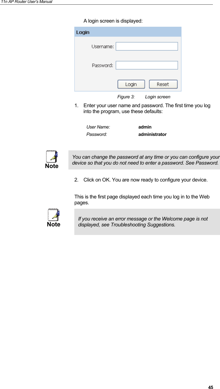
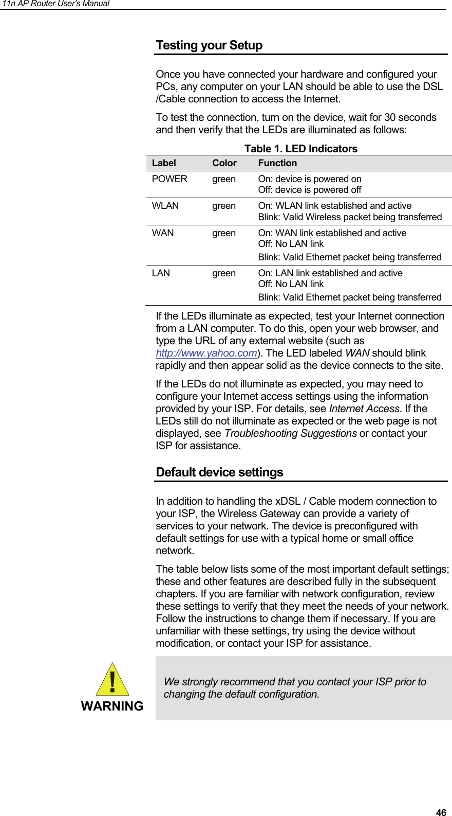
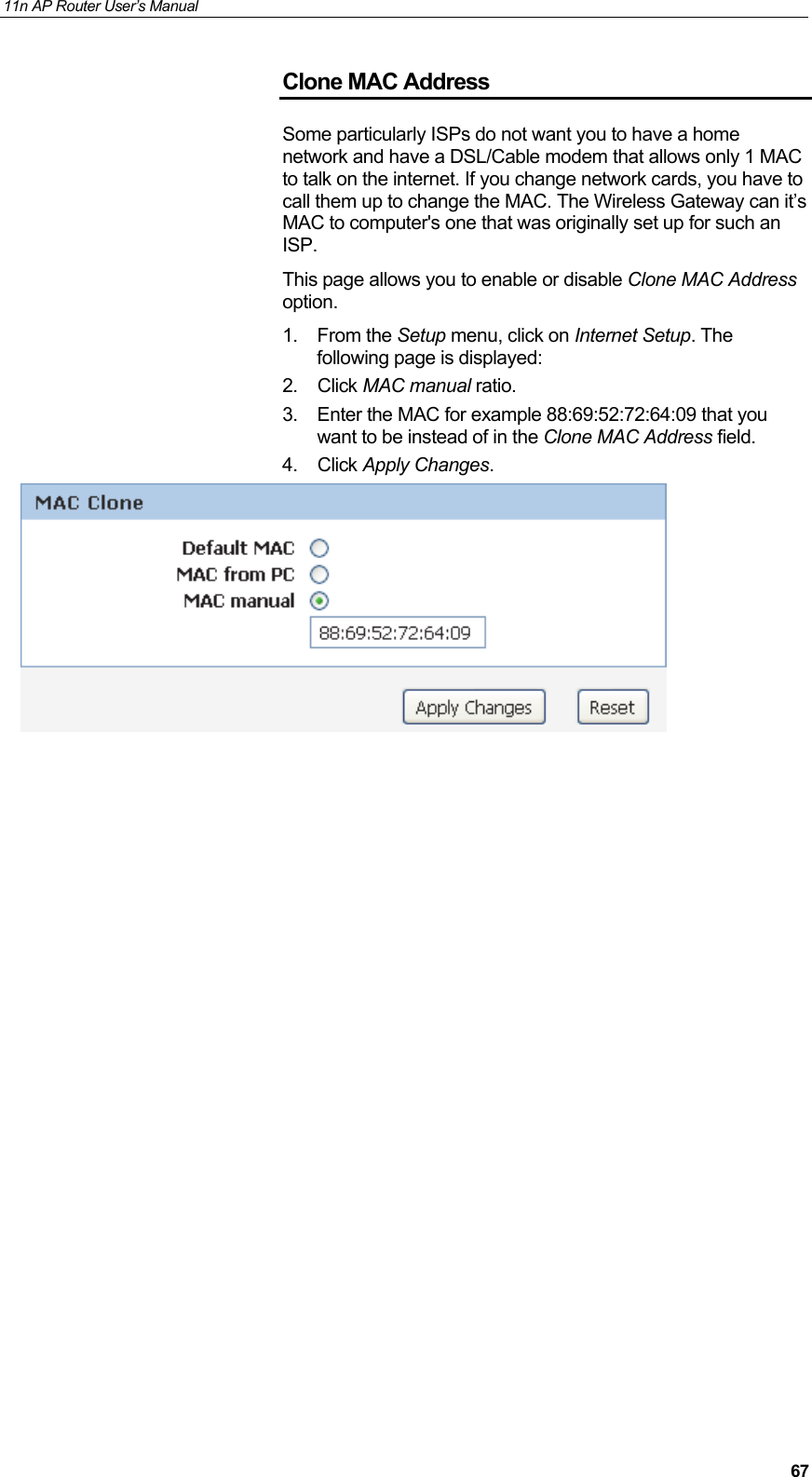
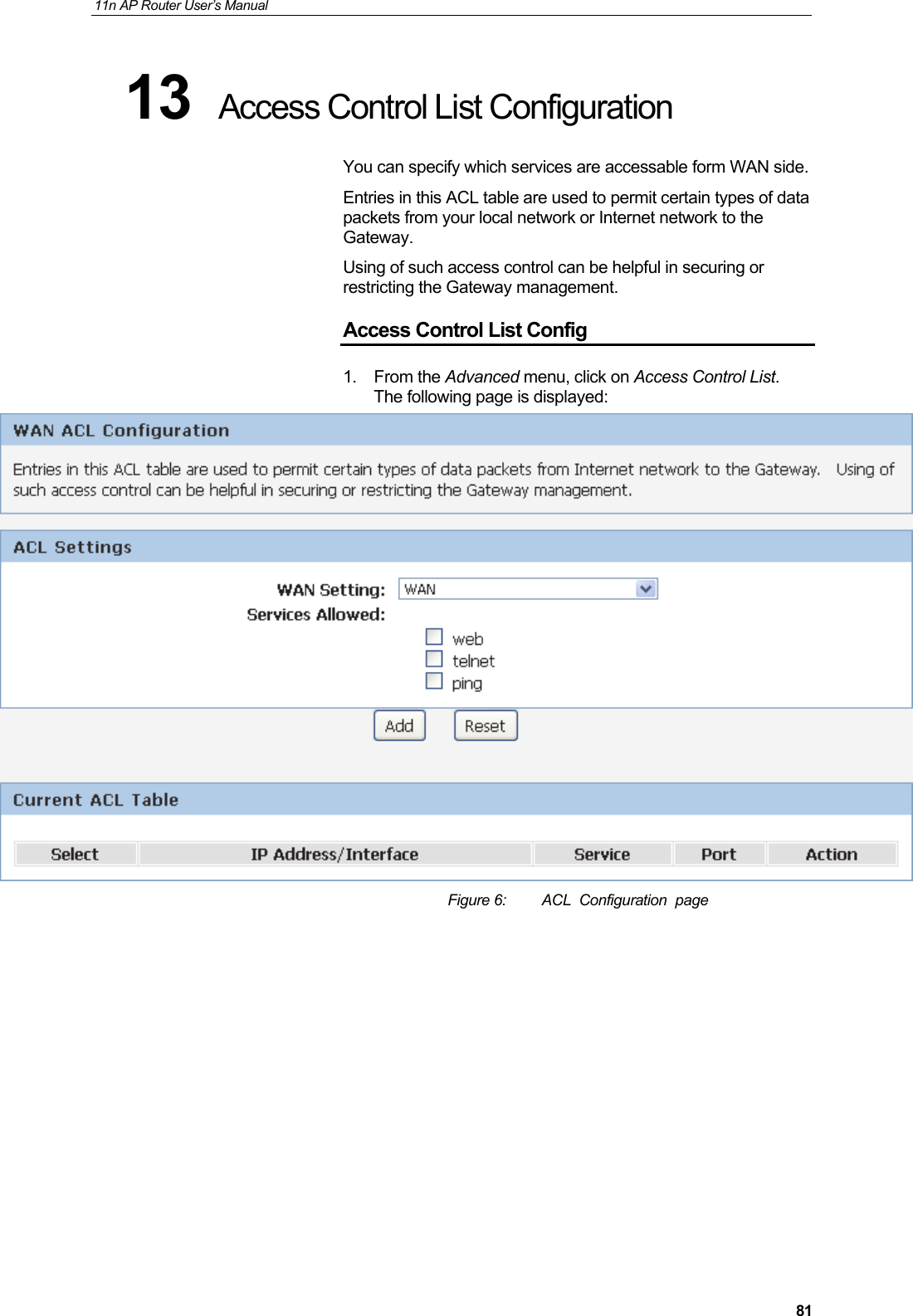
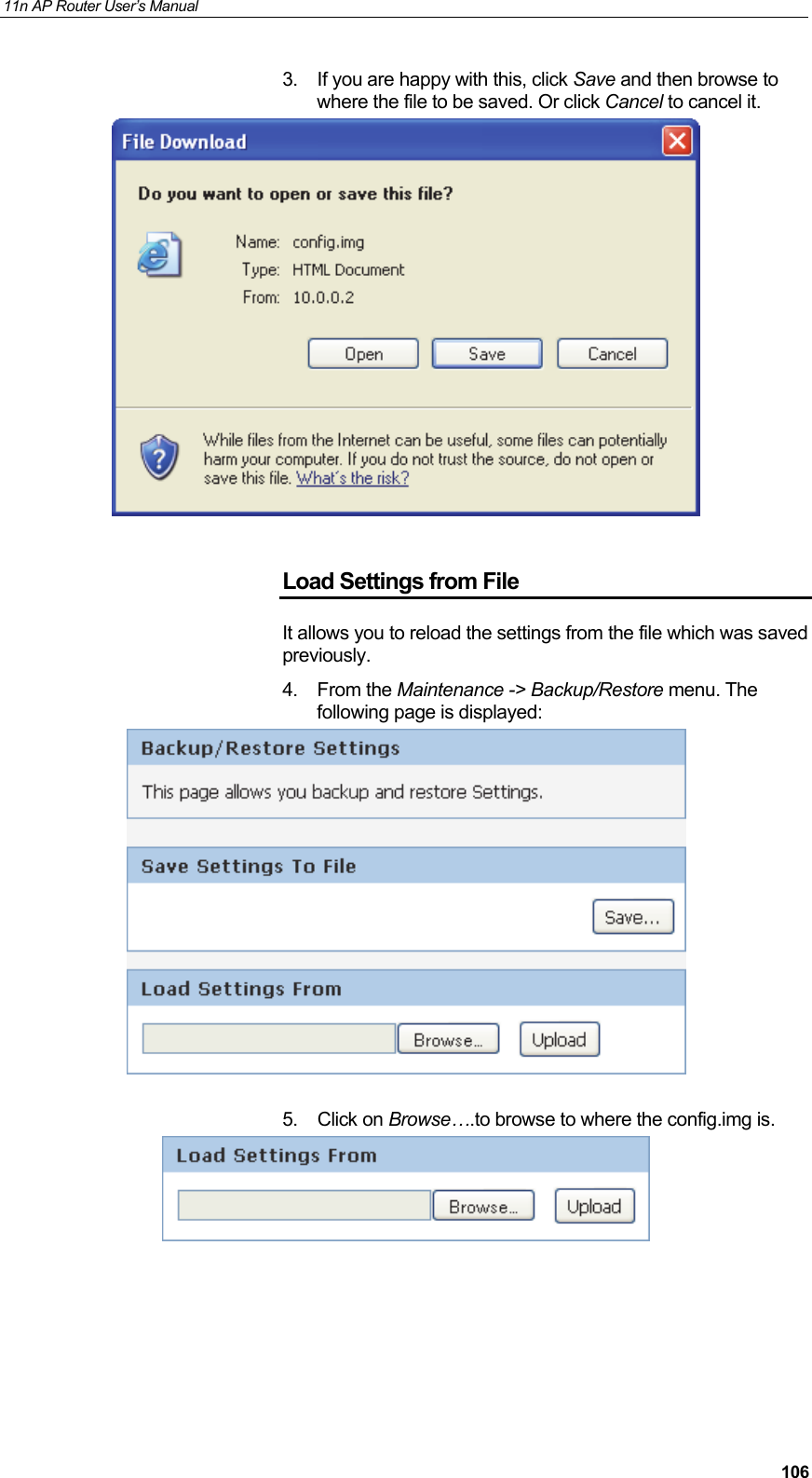
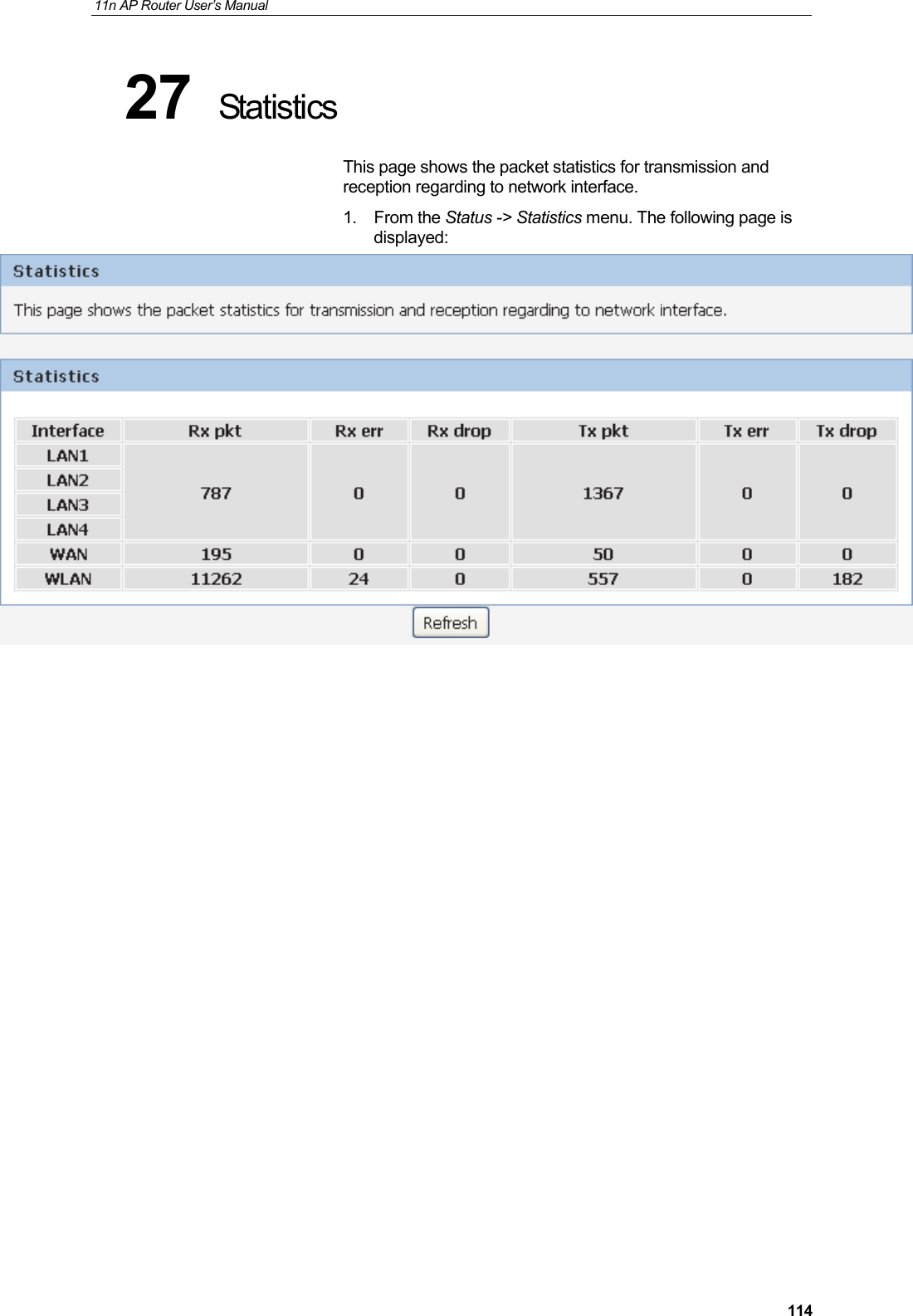
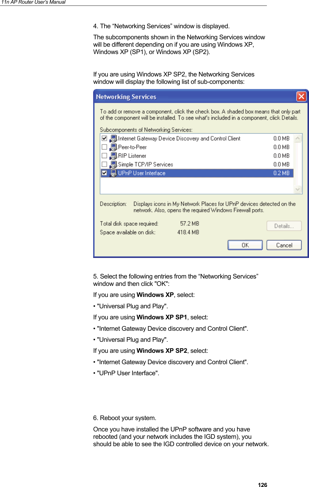
![11n AP Router User’s Manual 447 Getting Started with the Web pages The Wireless Gateway includes a series of Web pages that provide an interface to the software installed on the device. It enables you to configure the device settings to meet the needs of your network. You can access it through your web browser from any PC connected to the device via the LAN ports. Accessing the Web pages To access the Web pages, you need the following: • A PC or laptop connected to the LAN port on the device. • A web browser installed on the PC. The minimum browser version requirement is Internet Explorer v4 or Netscape v4. For the best display quality, use latest version of Internet Explorer, Netscape or Mozilla Fire fox. From any of the LAN computers, launch your web browser, type the following URL in the web address (or location) box, and press [Enter] on your keyboard: http://10.0.0.2 The Status homepage for the web pages is displayed: Figure 2: Homepage The first time that you click on an entry from the left-hand menu, a login box is displayed. You must enter your username and password to access the pages.](https://usermanual.wiki/Wedge-it-com/HHR1/User-Guide-2447222-Page-44.png)
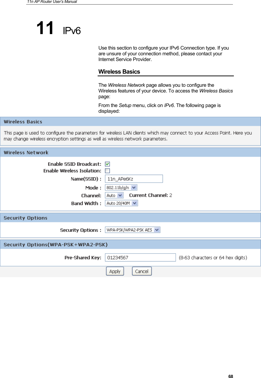
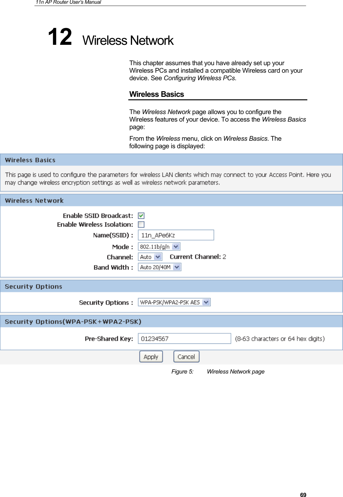
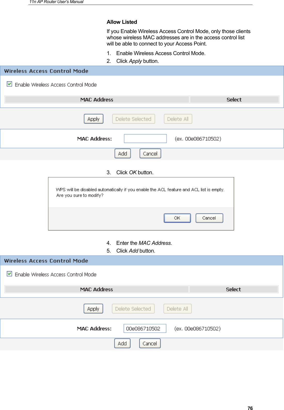
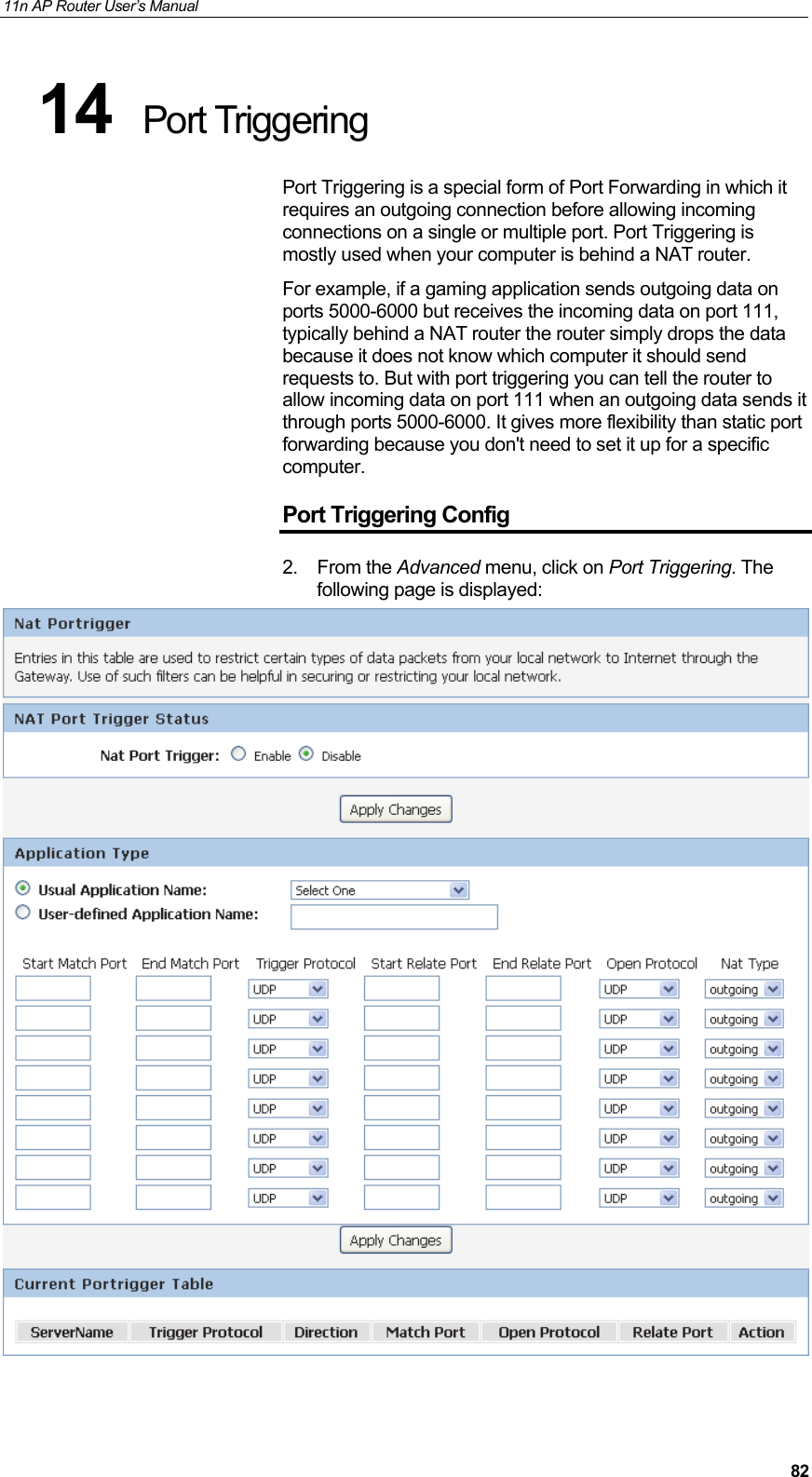
![11n AP Router User’s Manual 70Field Description Enable SSID Broadcast Broadcast or Hide SSID to your Network. Default: Enabled Enable Wireless Isolation Isolate your Network. Default: Disabled SSID Specify the network name. Each Wireless LAN network uses a unique Network Name to identify the network. This name is called the Service Set Identifier (SSID). When you set up your wireless adapter, you specify the SSID. If you want to connect to an existing network, you must use the name for that network. If you are setting up your own network you can make up your own name and use it on each computer. The name can be up to 20 characters long and contain letters and numbers. Mode Specify the WLAN Mode to 802.11b mode, 802.11g mode, 802.11b/g mode, 802.11n mode, 802.11n/g mode or 802.11b/g/n mode Channel Choose a Channel from the pull-down menu. Band Width Choose a Band Width from the pull-down menu. Max Transmission Rate Select the Max Transmission Rate from the drop-down list Security Options Configure the Encryption to None, WEP, WPA-PSK[TKIP] , WPA2-PSK[AES] or WPA-PSK/WPA2-PSK AES Security Encryption(WEP) Authentication Type: Automatic or Shared Keys Encryption Strength: 64 bits or 128 bits Security Encryption(WEP) Key Select and configure Key 1, Key 2, Key 3 or Key 4 Security Options(WPA-PSK) Enter the Pre-Shared Key Security Options(WPA2-PSK) Enter the Pre-Shared Key Security Options(WPA-PSK+WPA2-PSK) Enter the Pre-Shared Key](https://usermanual.wiki/Wedge-it-com/HHR1/User-Guide-2447222-Page-70.png)
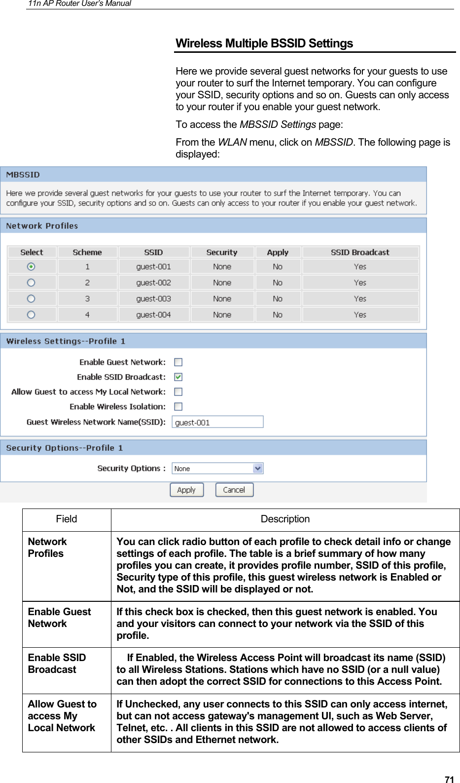
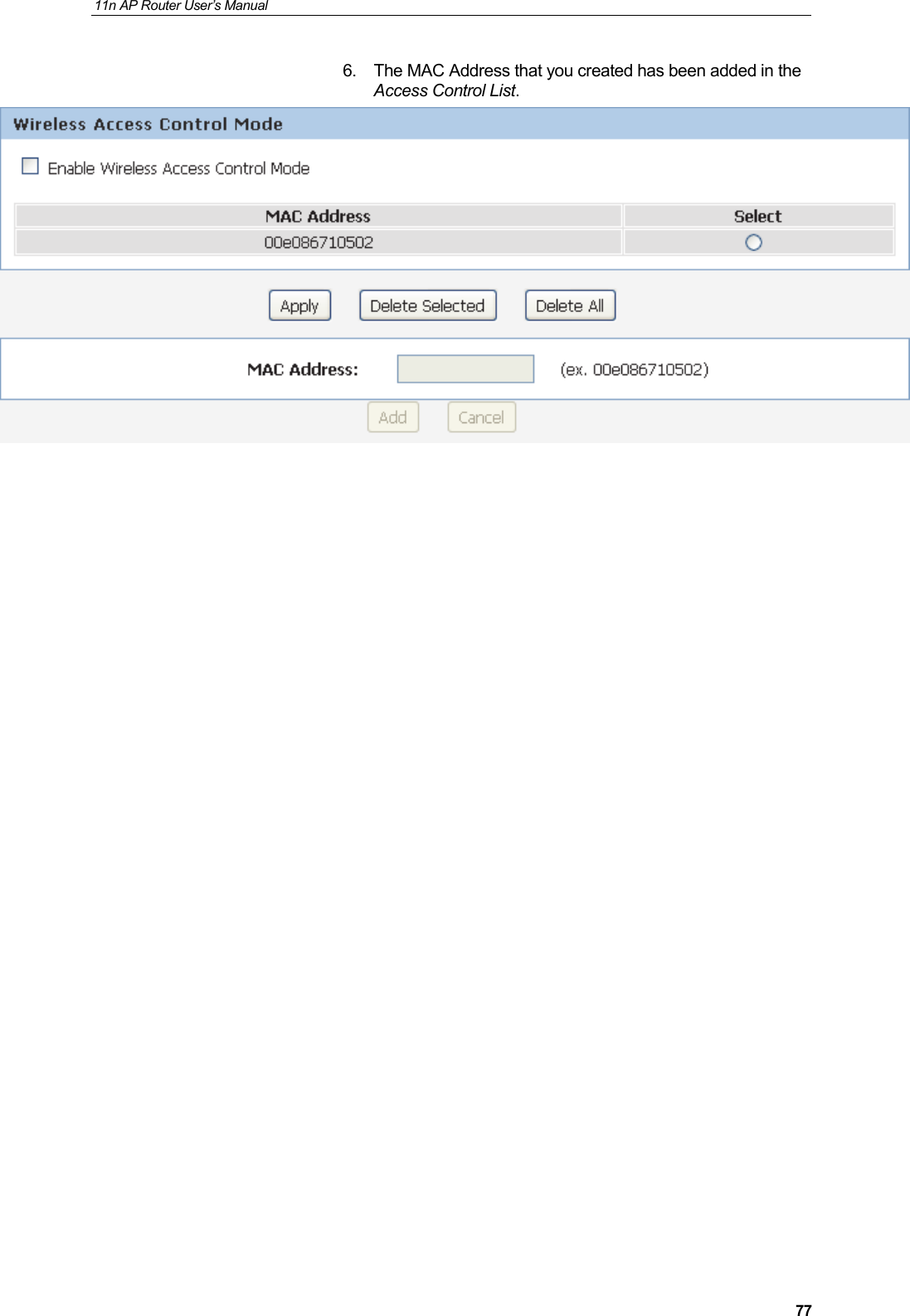
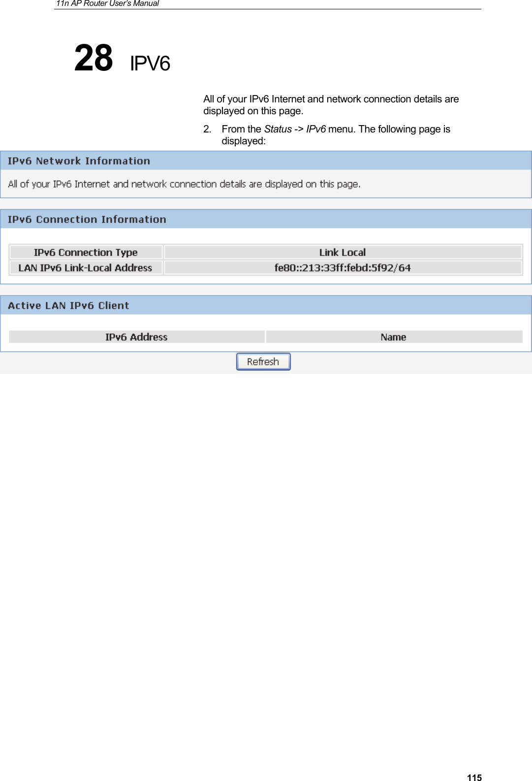
![11n AP Router User’s Manual 72If Checked, any user who connects to this SSID can access not only internet but also local networks of this wireless router like users in primary SSID. Enable Wireless Isolation If checked, the wireless client under this SSID can`t access other wireless clients under the same SSID. If unchecked, the wireless client under this SSID can access other wireless clients under the same SSID. Guest Wireless Network Name(SSID) Enter a value of up to 32 alphanumeric characters. The same Name (SSID) must be assigned to all wireless devices in your network. The default SSID is SSID_N, N is profile number, but we strongly recommend that you change your network`s Name (SSID) to a different value. This value is also case-sensitive. For example, SSID is not the same as SSId. Security Options None - no data encryption WEP - Wired Equivalent Privacy, use WEP 64- or 128-bit data encryptionNote: Wi-Fi Protected Setup function is disabled when the security setting is WEP with Shared-Key authentication WPA-PSK [TKIP] - Wi-Fi Protected Access with Pre-Shared Key, use WPA-PSK standard encryption with TKIP encryption type WPA2-PSK [AES] - Wi-Fi Protected Access version 2 with Pre-Shared Key, use WPA2-PSK standard encryption with the AES encryption type WPA-PSK [AES] + WPA2-PSK [AES] - Allow clients using either WPA-PSK [AES] or WPA2-PSK [AES] To achieve the best performance with 11N wireless adapters under robust security network, we recommends that you change your network`s security option to WPA2-PSK.](https://usermanual.wiki/Wedge-it-com/HHR1/User-Guide-2447222-Page-72.png)
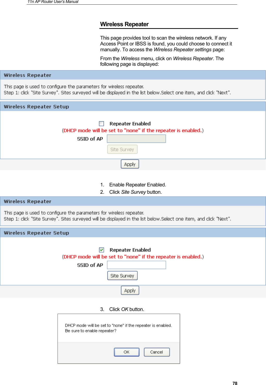

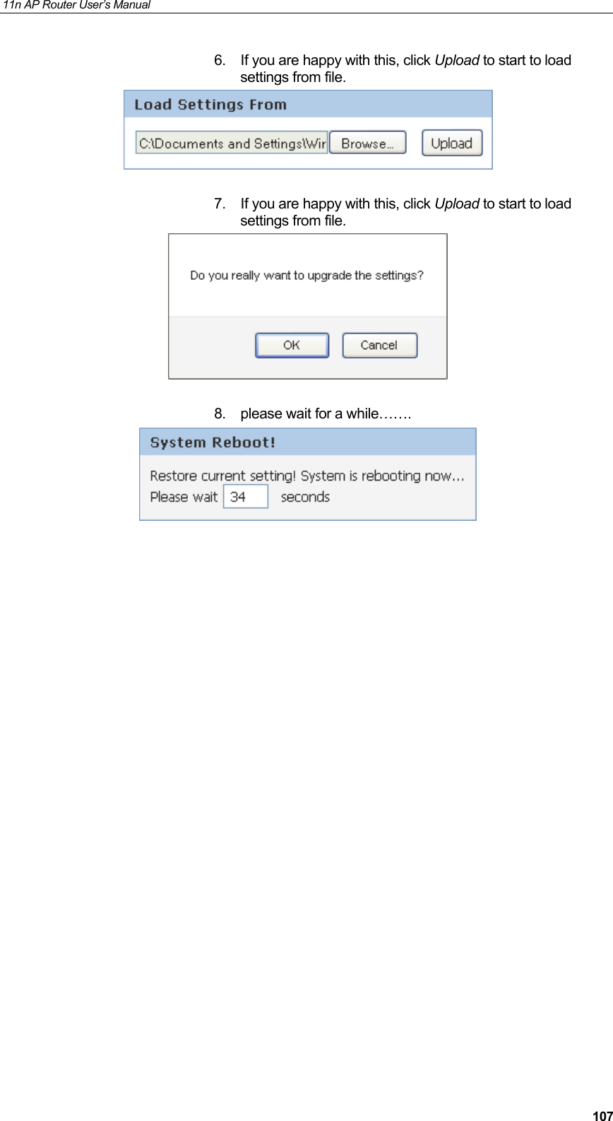
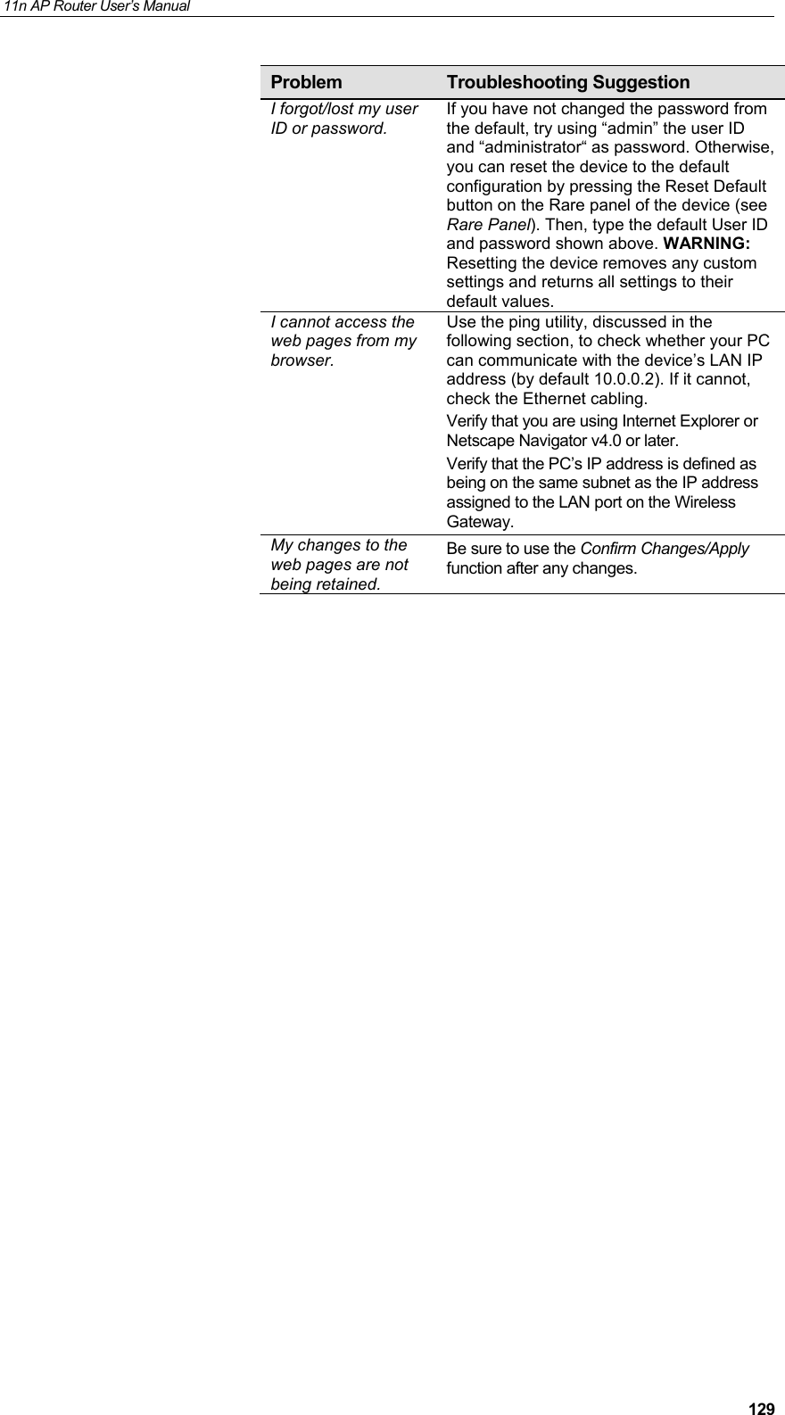
![錯誤! 使用 [常用] 索引標籤將 Title 套用到您想要在此處顯示的文字。 User’s Guide Troubleshooting D Troubleshooting This appendix suggests solutions for problems you may encounter in installing or using the Wireless Gateway, and provides instructions for using several IP utilities to diagnose problems. Contact Customer Support if these suggestions do not resolve the problem. Troubleshooting Suggestions Problem Troubleshooting Suggestion LEDs Power LED does not illuminate after product is turned on.Verify that you are using the power cable provided with the device and that it is securely connected to the Wireless Gateway and a wall socket/power strip. LINK LAN LED does not illuminate after Ethernet cable is attached. Verify that the Ethernet cable is securely connected to your LAN hub or PC and to the Wireless Gateway. Make sure the PC and/or hub is turned on. Verify that your cable is sufficient for your network requirements. A 100 Mbit/sec network (10BaseTx) should use cables labeled CAT 5. A 10Mbit/sec network may tolerate lower quality cables. Internet Access My PC cannot access the Internet Use the ping utility (discussed in the following section) to check whether your PC can communicate with the device’s LAN IP address (by default 10.0.0.2). If it cannot, check the Ethernet cabling. If you statically assigned a private IP address to the computer, (not a registered public address), verify the following: • Check that the gateway IP address on the computer is your public IP address (see Current Status for instructions on viewing the IP information.) If it is not, correct the address or configure the PC to receive IP information automatically. • Verify with your ISP that the DNS server specified for the PC is valid. Correct the address or configure the PC to receive this information automatically. My LAN PCs cannot display web pages on the Internet. Verify that the DNS server IP address specified on the PCs is correct for your ISP, as discussed in the item above. If you specified that the DNS server be assigned dynamically from a server, then verify with your ISP that the address configured on the Wireless Gateway is correct, then You can use the ping utility, to test connectivity with your ISP’s DNS server. Web pages](https://usermanual.wiki/Wedge-it-com/HHR1/User-Guide-2447222-Page-128.png)
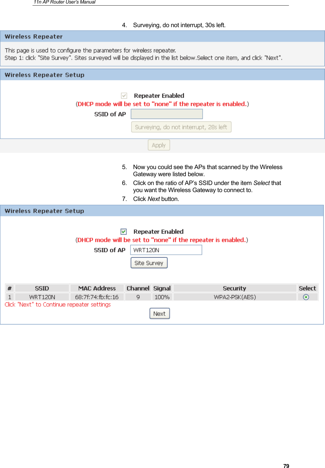
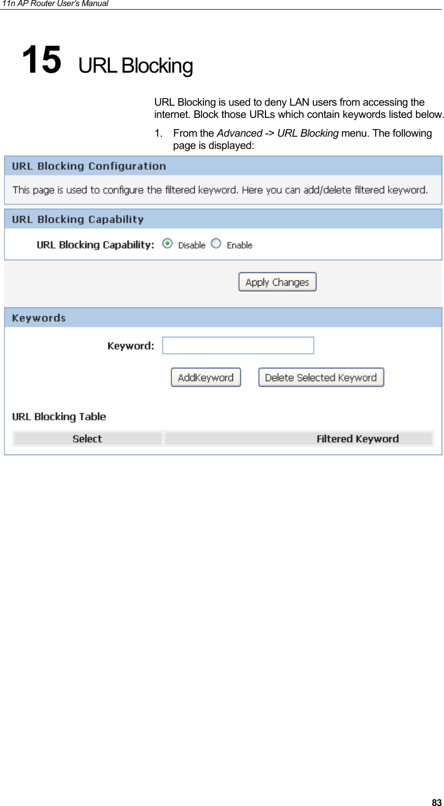
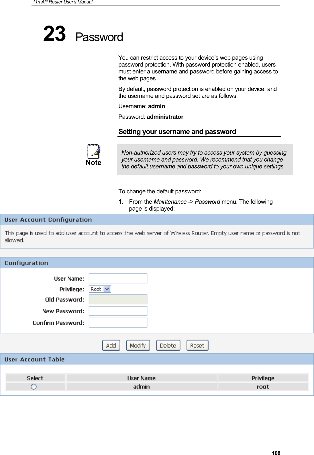
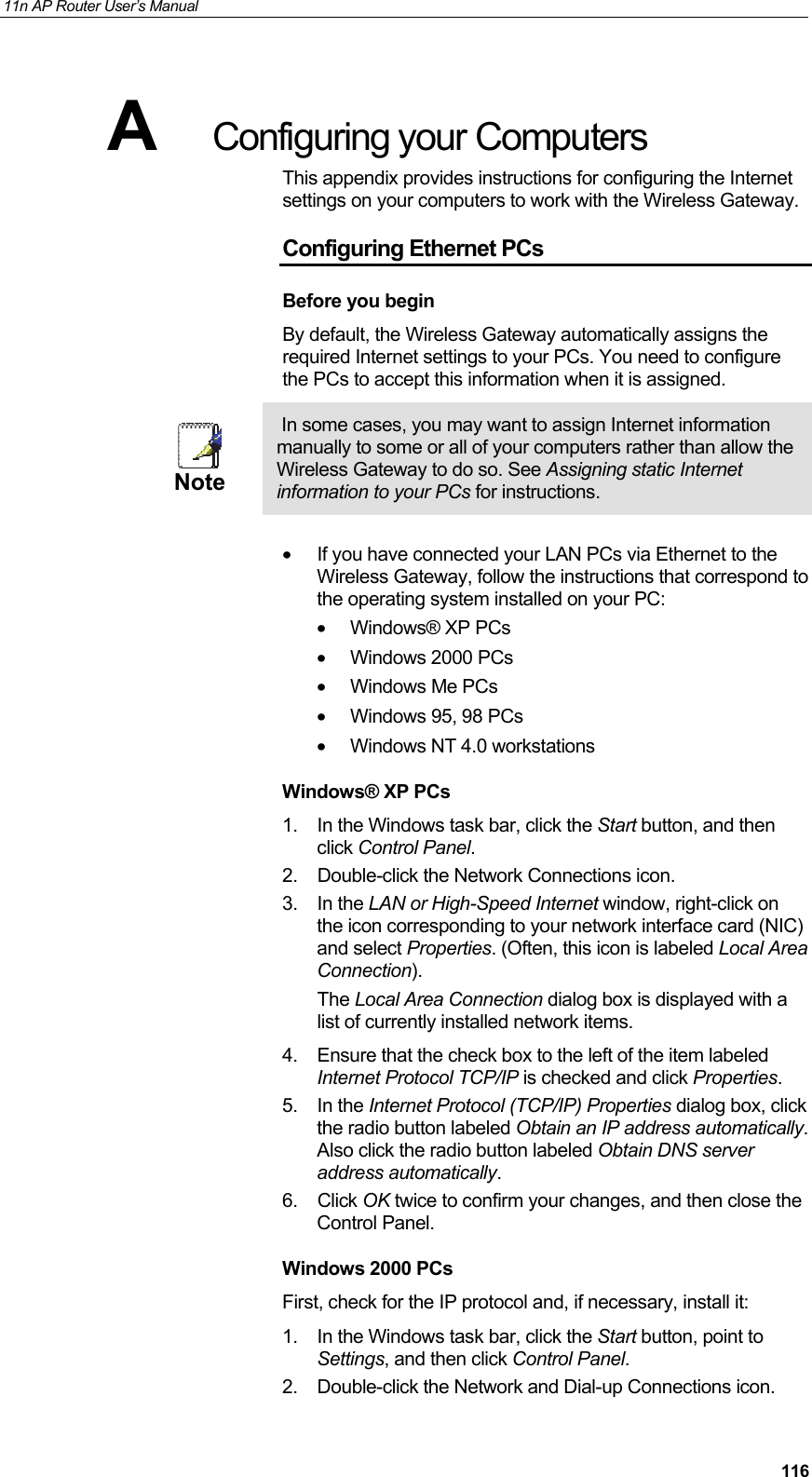
![11n AP Router User’s Manual 131name is not an entry in your ISP’s DNS table, the request is then referred to another higher-level server, and so on, until the entry is found. The server then returns the associated IP address. On Windows-based computers, you can execute the nslookup command from the Start menu. Click the Start button, and then click Run. In the Open text box, type the following: Nslookup Click OK. A Command Prompt window displays with a bracket prompt (>). At the prompt, type the name of the Internet address that you are interested in, such as www.microsoft.com. The window will display the associate IP address, if known, as shown below: Figure 10: Using the nslookup Utility There may be several addresses associated with an Internet name. This is common for web sites that receive heavy traffic; they use multiple, redundant servers to carry the same information. To exit from the nslookup utility, type exit and press [Enter] at the command prompt.](https://usermanual.wiki/Wedge-it-com/HHR1/User-Guide-2447222-Page-131.png)