3M Traffic Safety Systems 6204 3M UHF RFID Reader User Manual
3M Traffic Safety Systems 3M UHF RFID Reader
UserManual.wiki
>
3M Traffic Safety Systems
>
6204 User Manual
>
User manual
Contents
1.
User manual
2.
Users manual
User manual
Navigation menu
Upload a User Manual
Namespaces
Wiki Guide
HTML
PDF
Info
Views
User Manual
Discussion / Help
Navigation
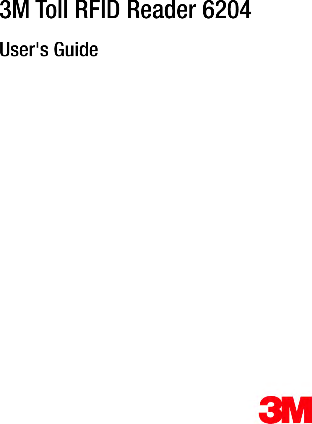

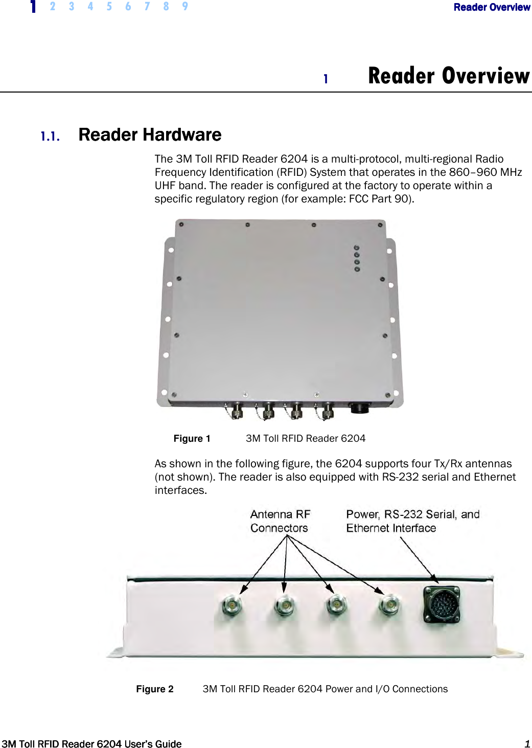
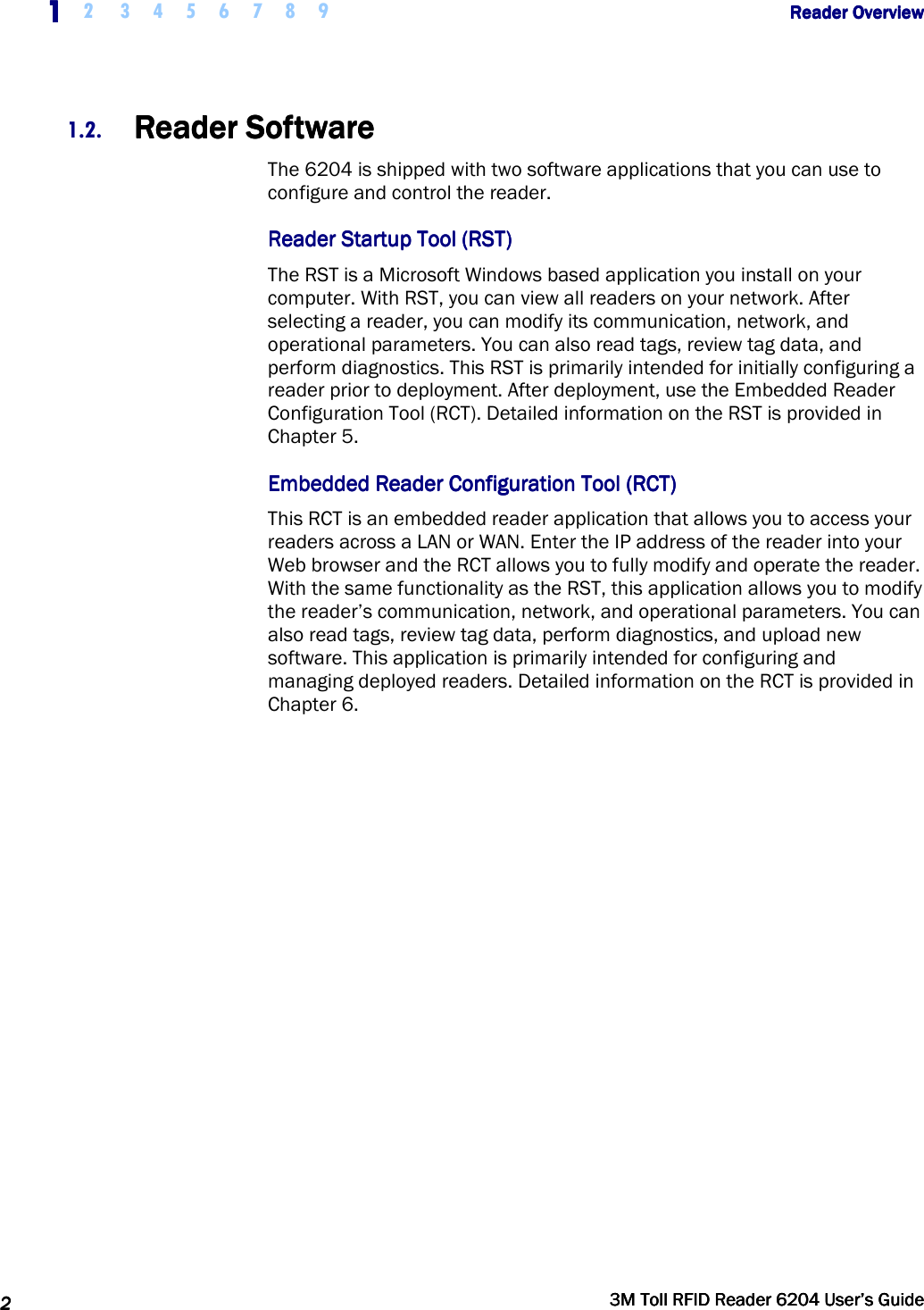

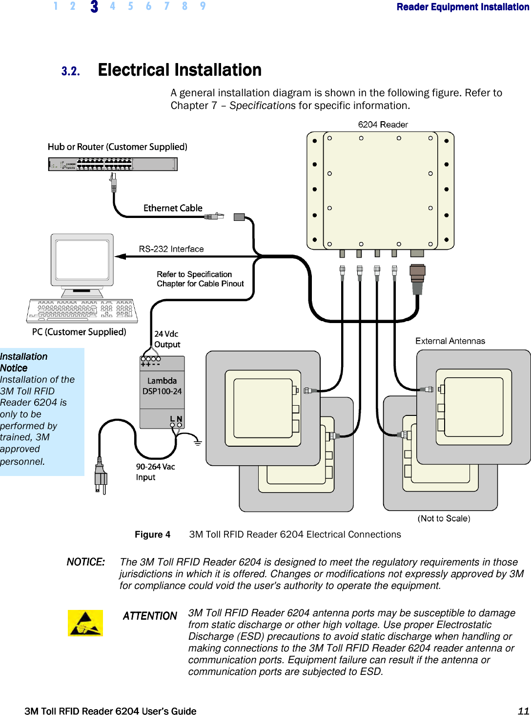
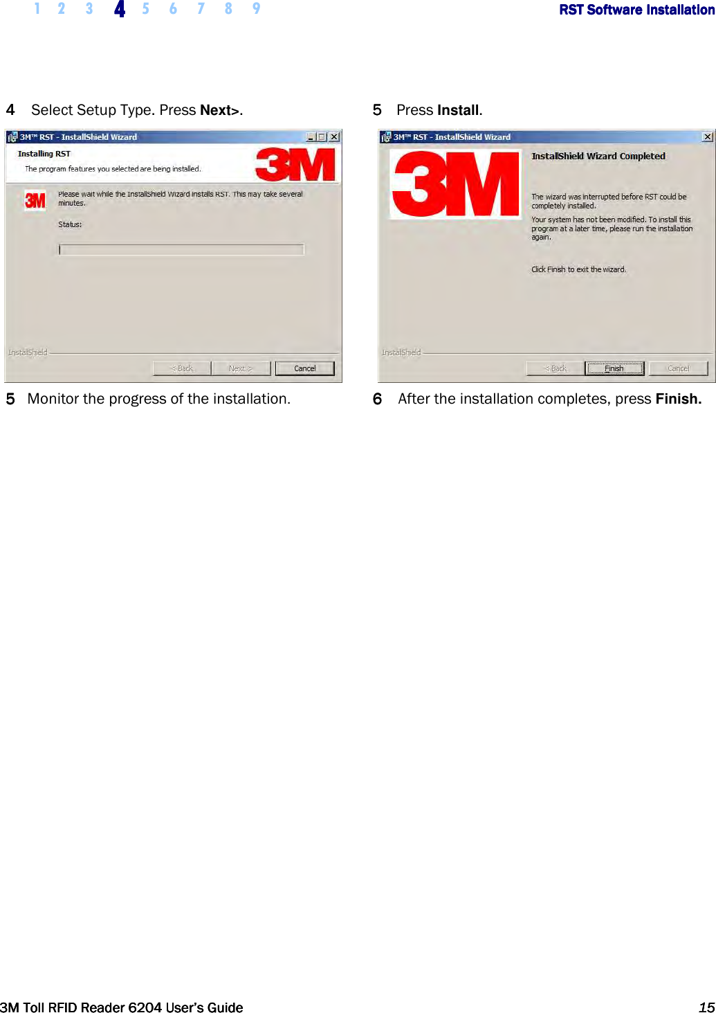
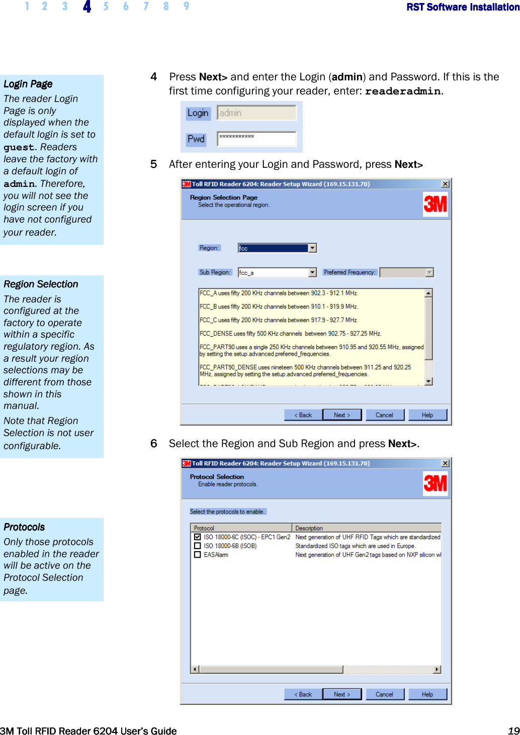
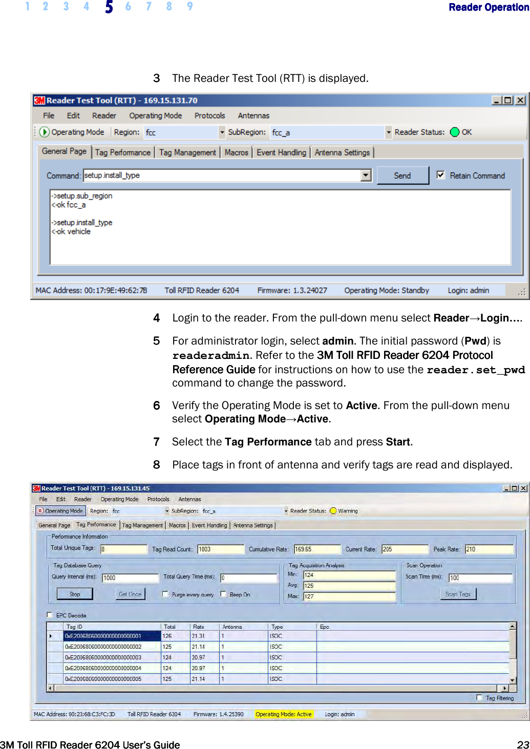
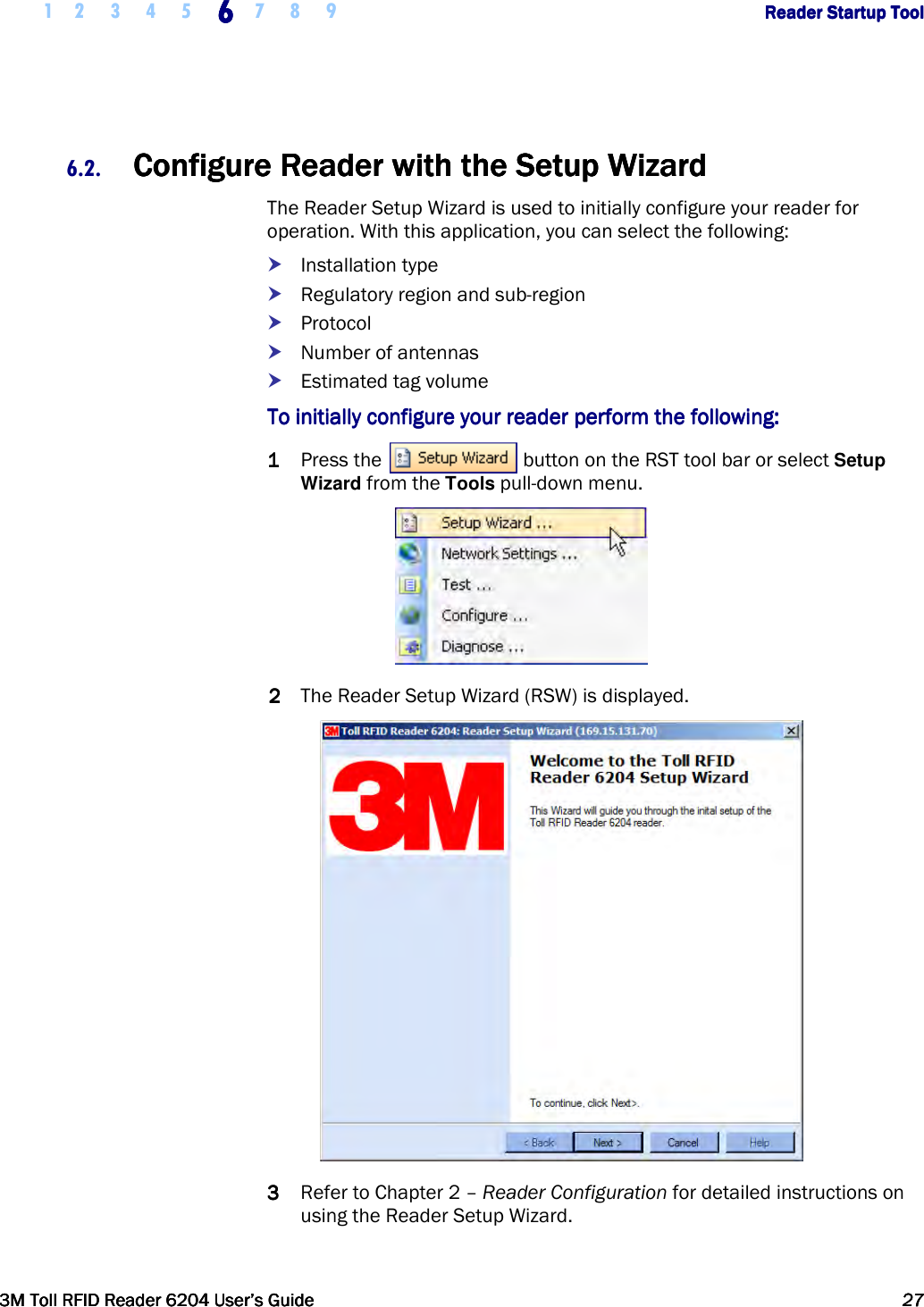
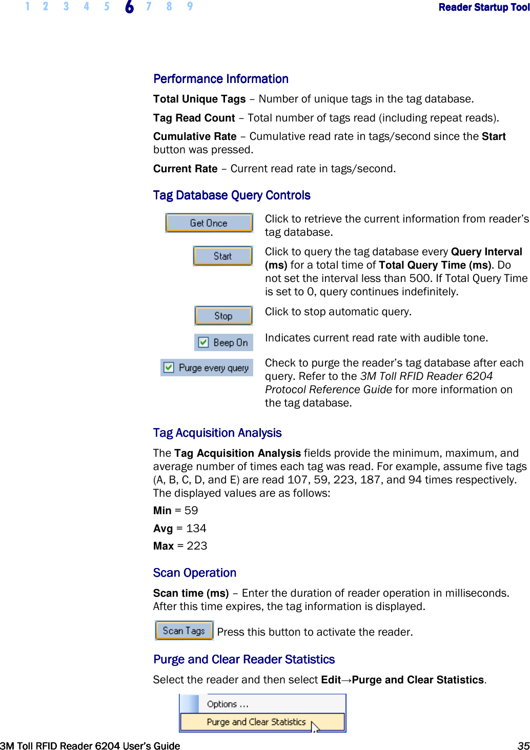
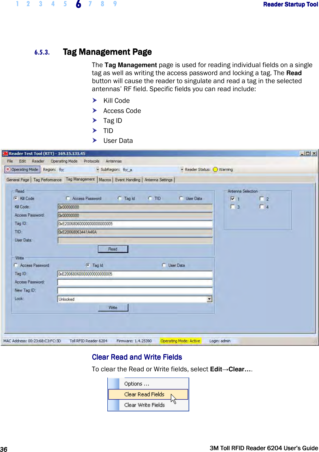
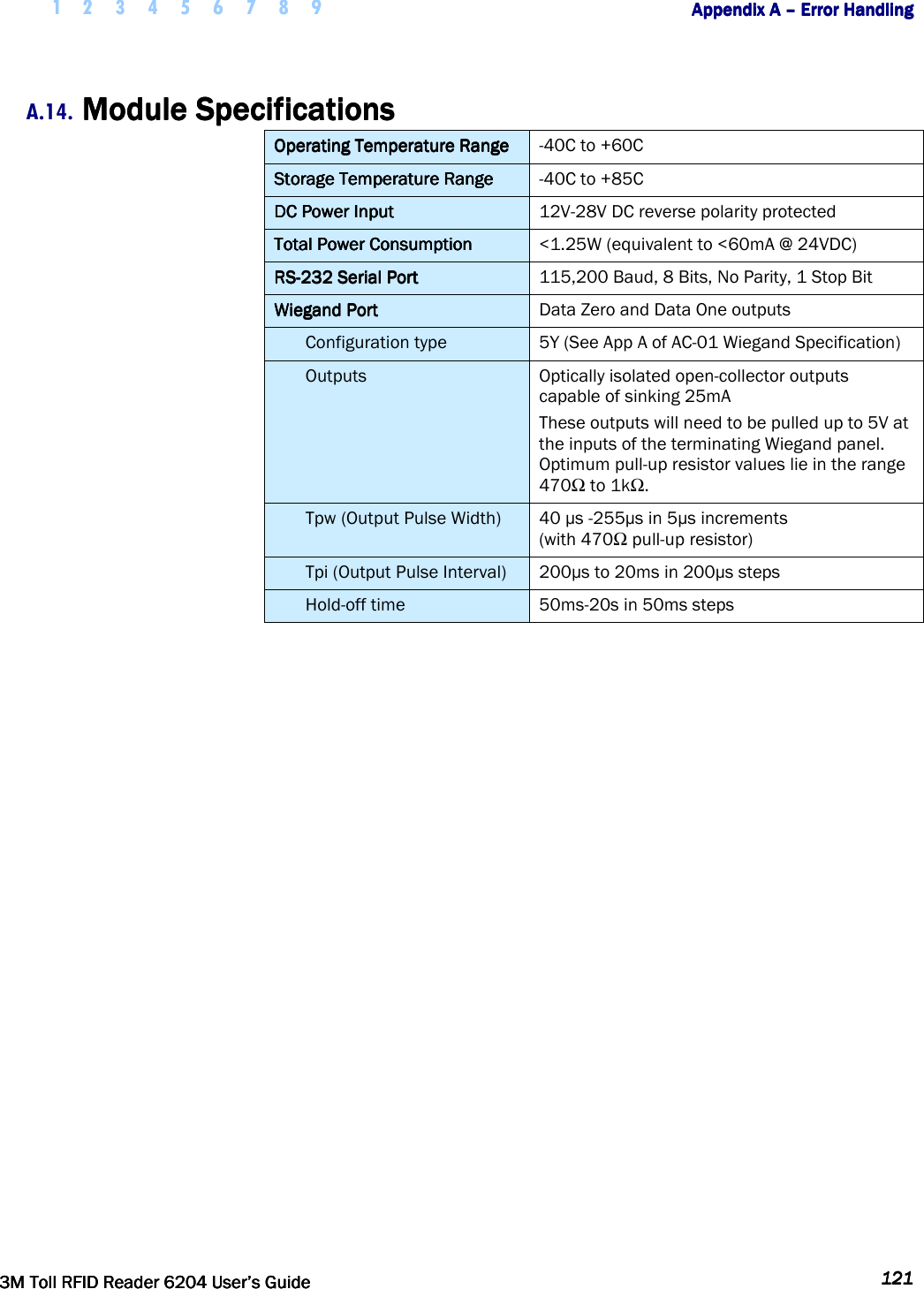
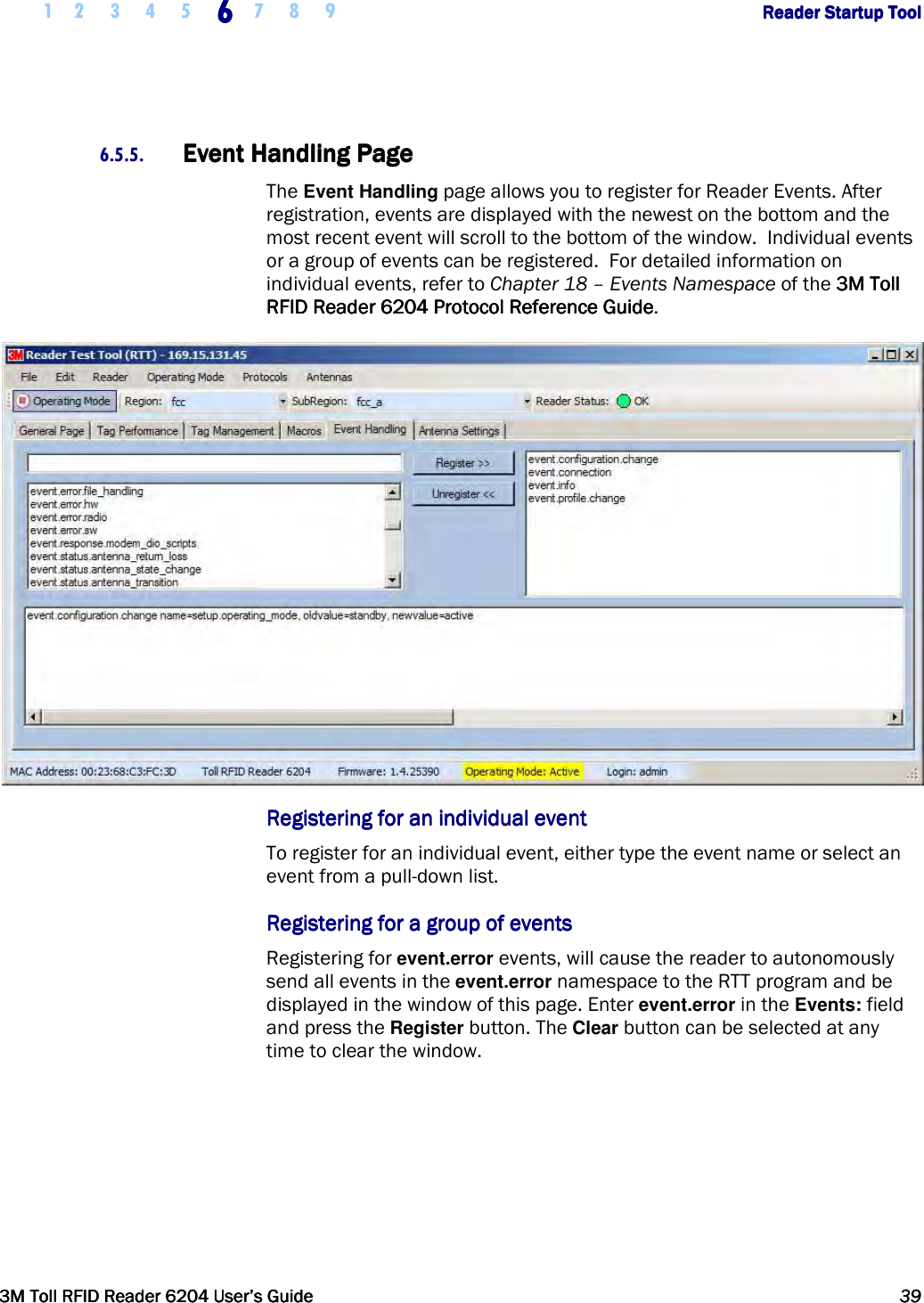
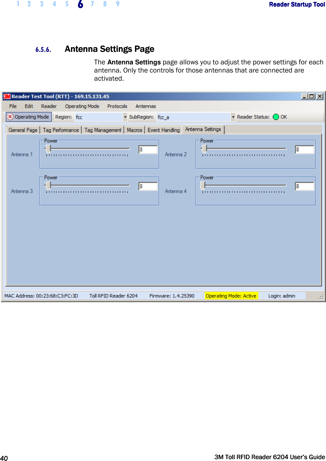
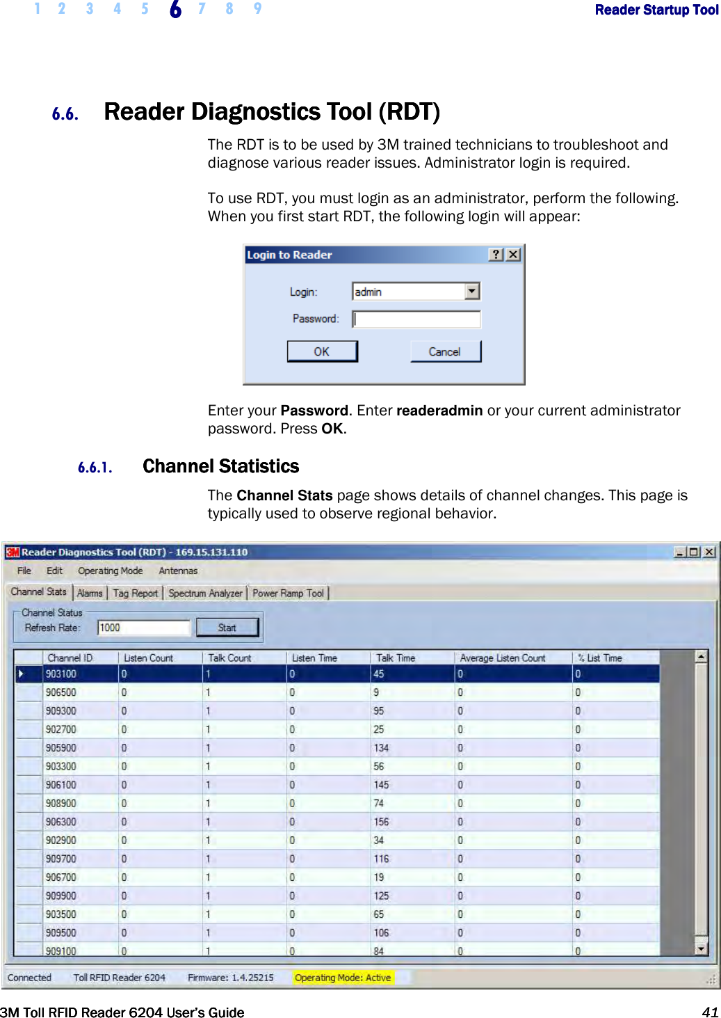
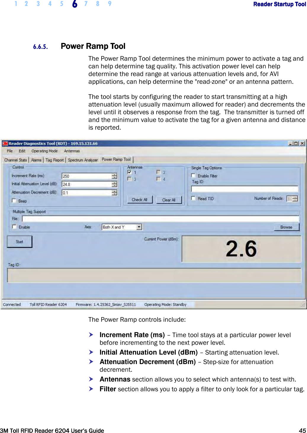
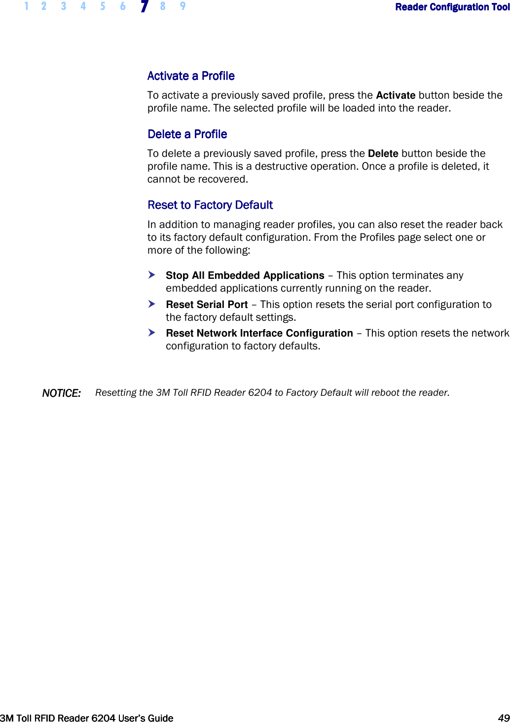
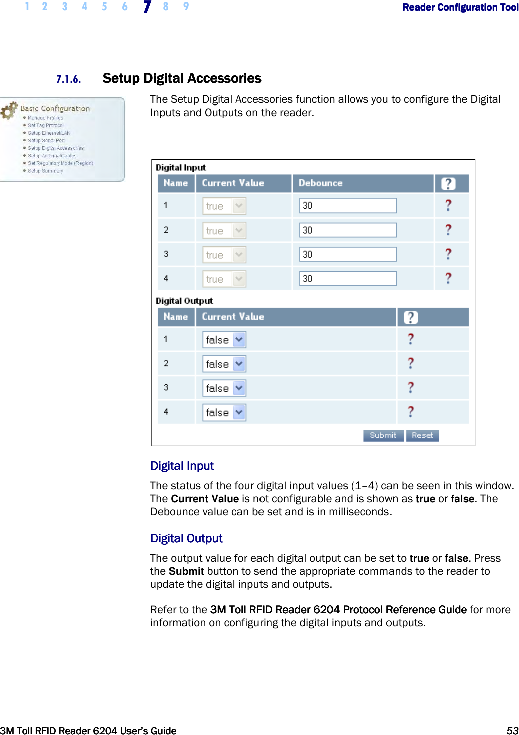
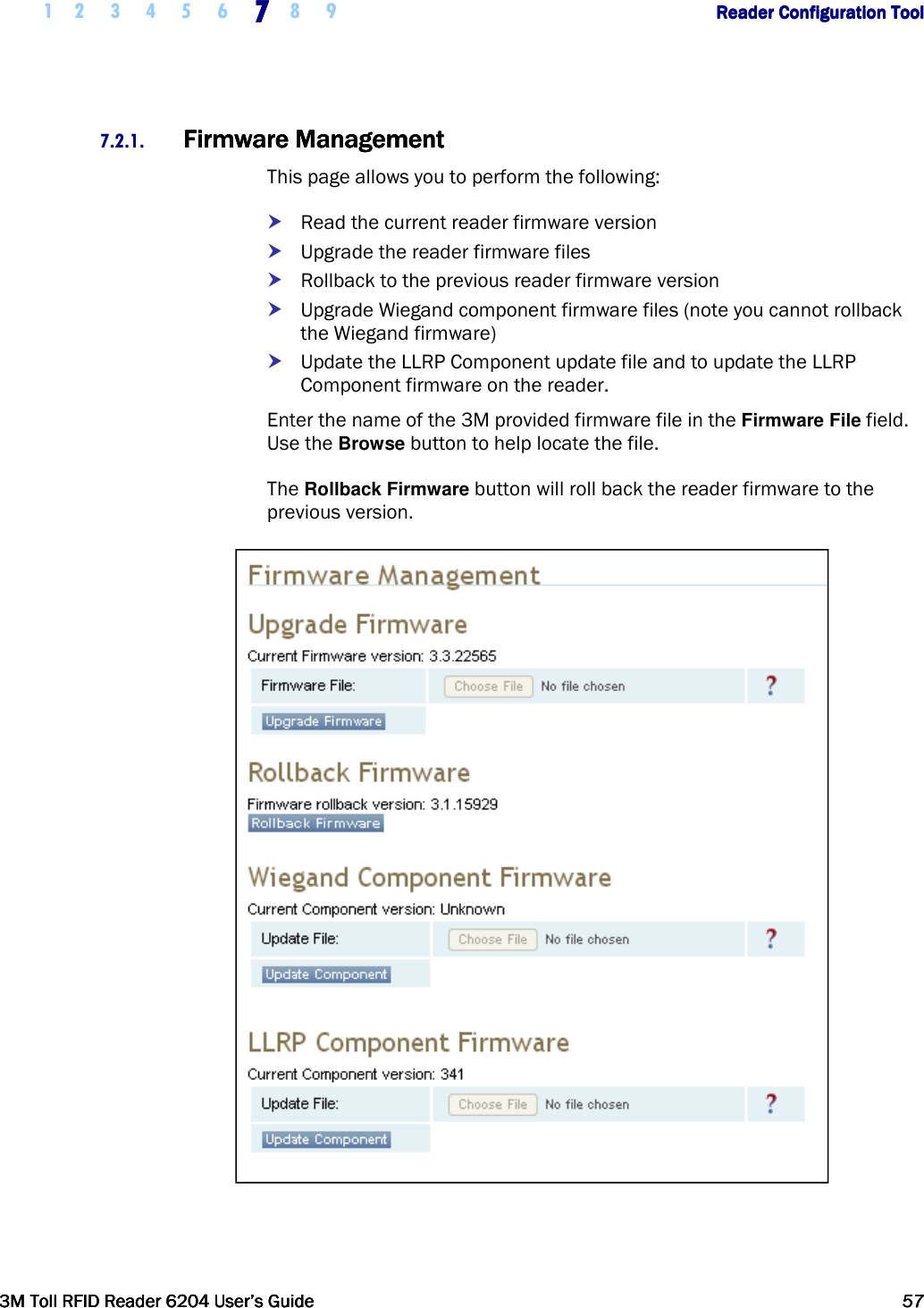
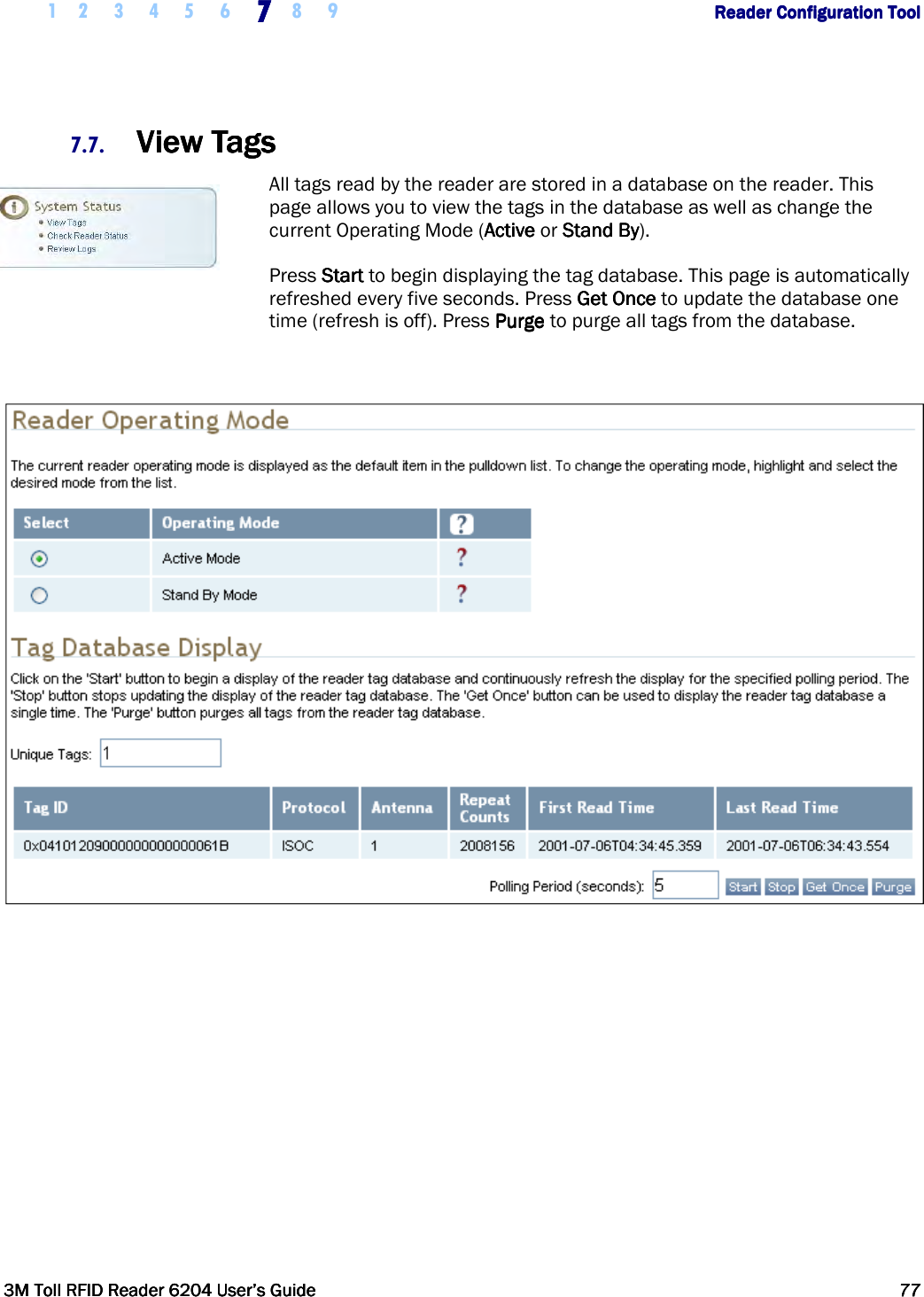
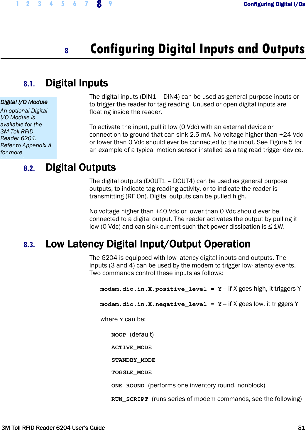
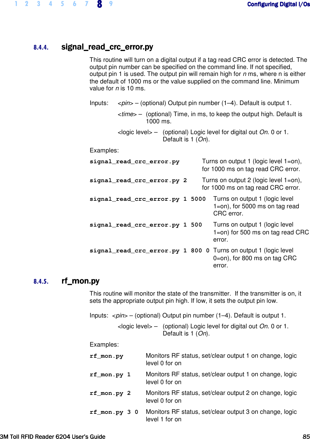
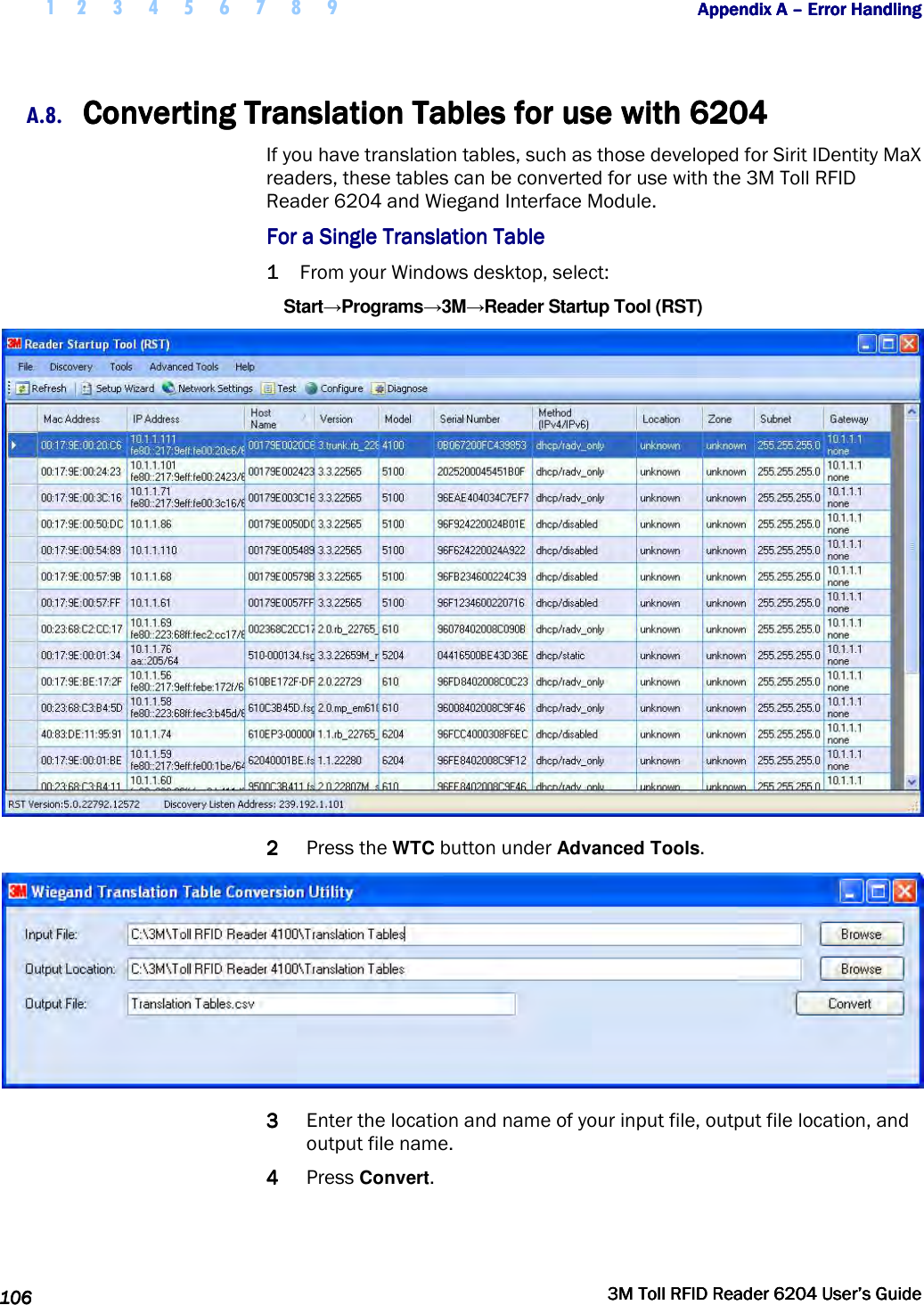
![1 2 3 4 5 6666 7 8 9 Reader Startup ToolReader Startup ToolReader Startup ToolReader Startup Tool 3M Toll RFID Reader 62043M Toll RFID Reader 62043M Toll RFID Reader 62043M Toll RFID Reader 6204 User’s GuideUser’s GuideUser’s GuideUser’s Guide 37373737 6.5.4. Macros PageMacros PageMacros PageMacros Page The Macros page allows the reader to manage macro files. The macros are provided by 3M or can be written by the end user. Some of the macros provided are dependent on the operating region of the reader. A macro (script or command file) is a text file that contains one or more reader commands. These commands are used to configure the reader to a known configuration. The Macros can contain variables. These variables are resolved by a dialog box (Macro Variables) that appears when the Send to Reader button is selected. The syntax of a variable is: [$variable_name] During execution, the variable is replaced with user entries into the Macro Variables dialog box. Macros can be edited with any text editor including Windows Notepad.](https://usermanual.wiki/3M-Traffic-Safety-Systems/6204.User-manual/User-Guide-2464263-Page-49.png)
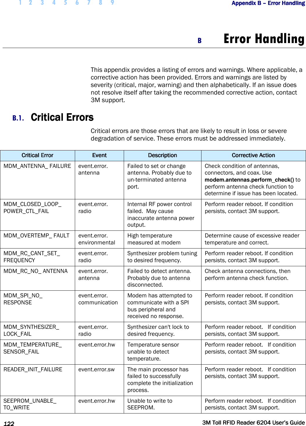
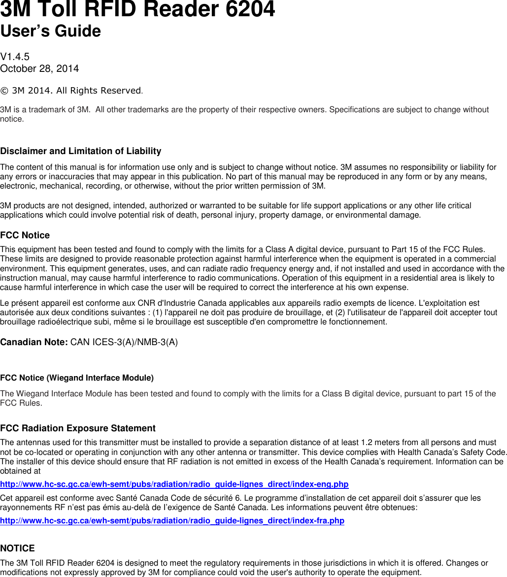
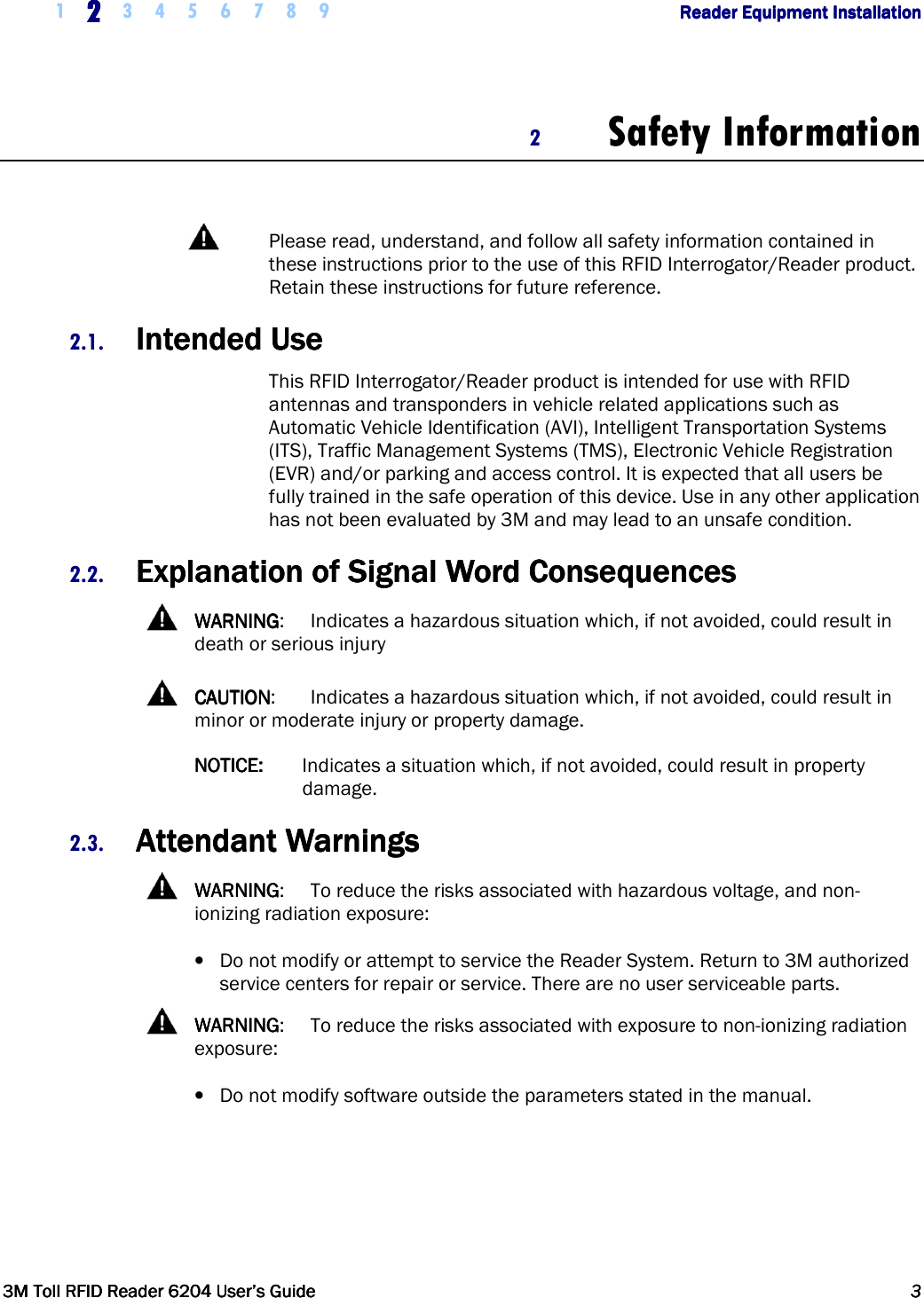
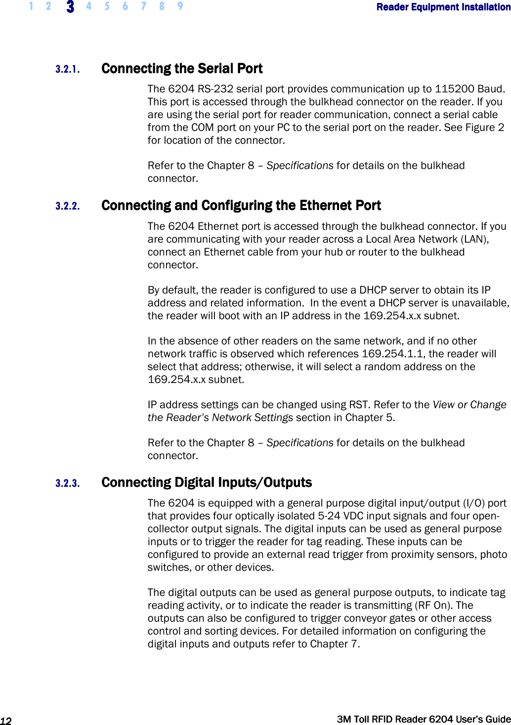
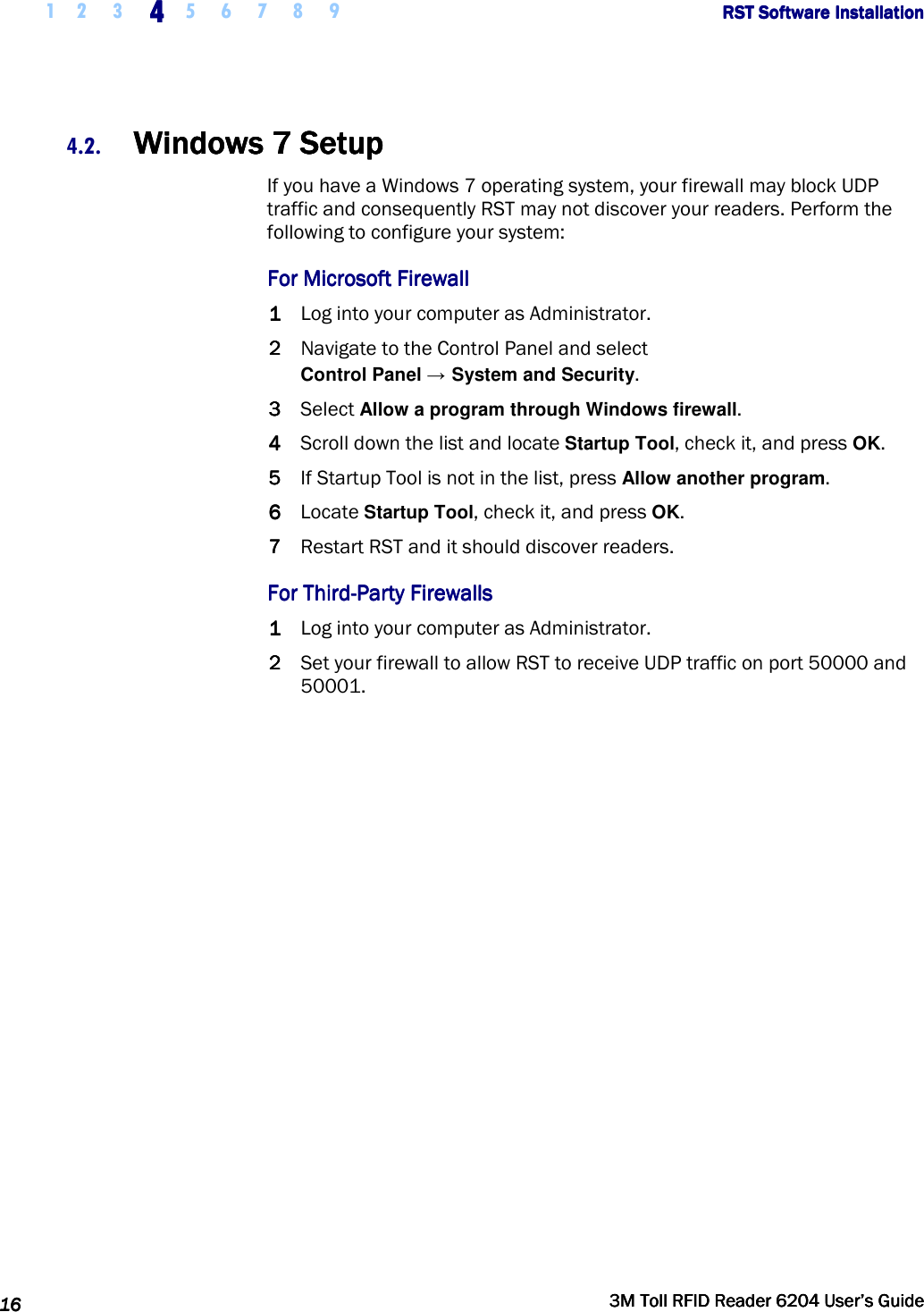
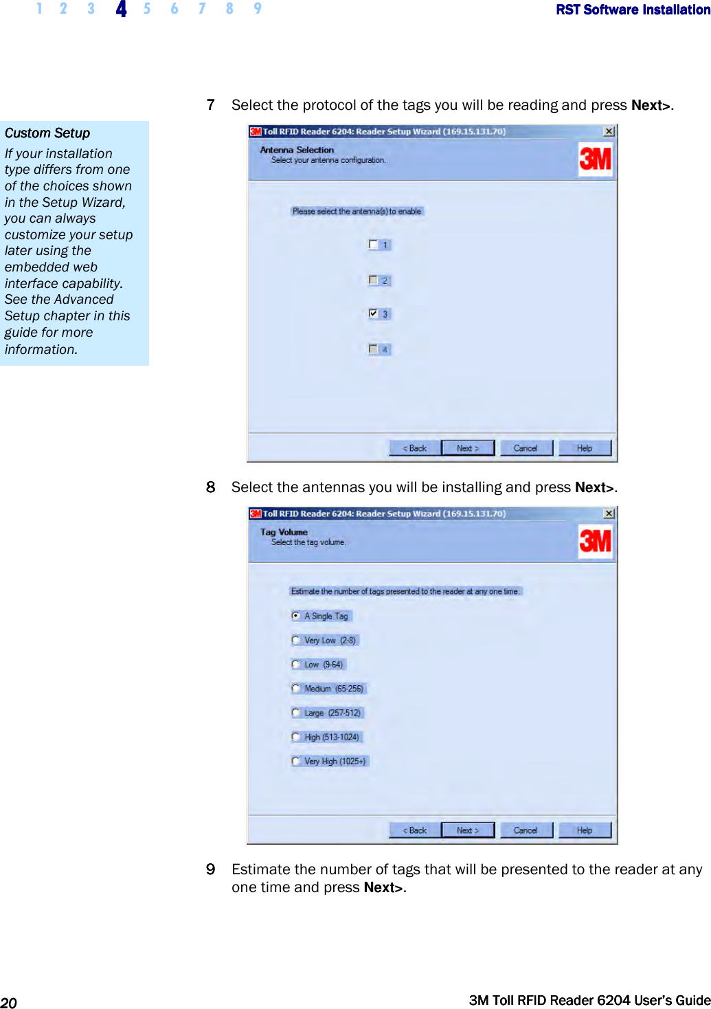
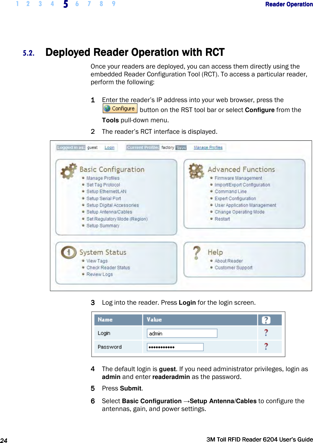
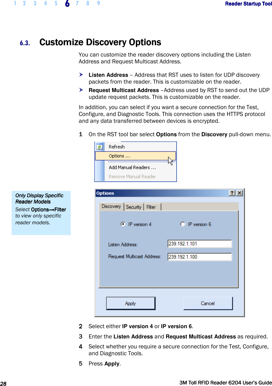
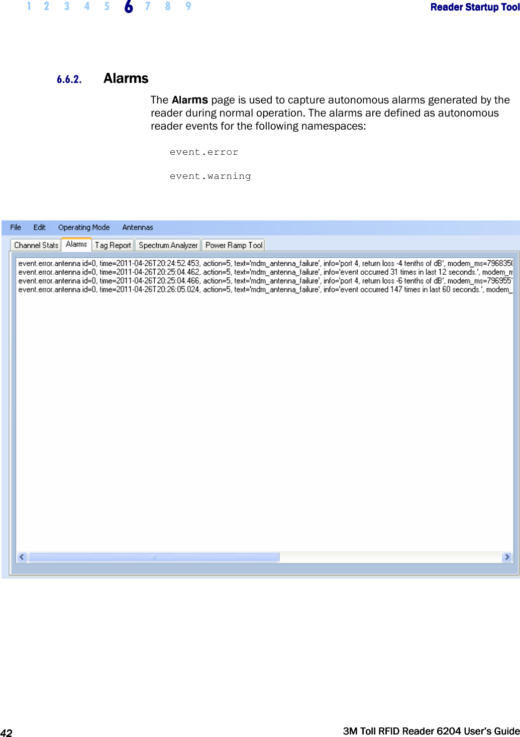
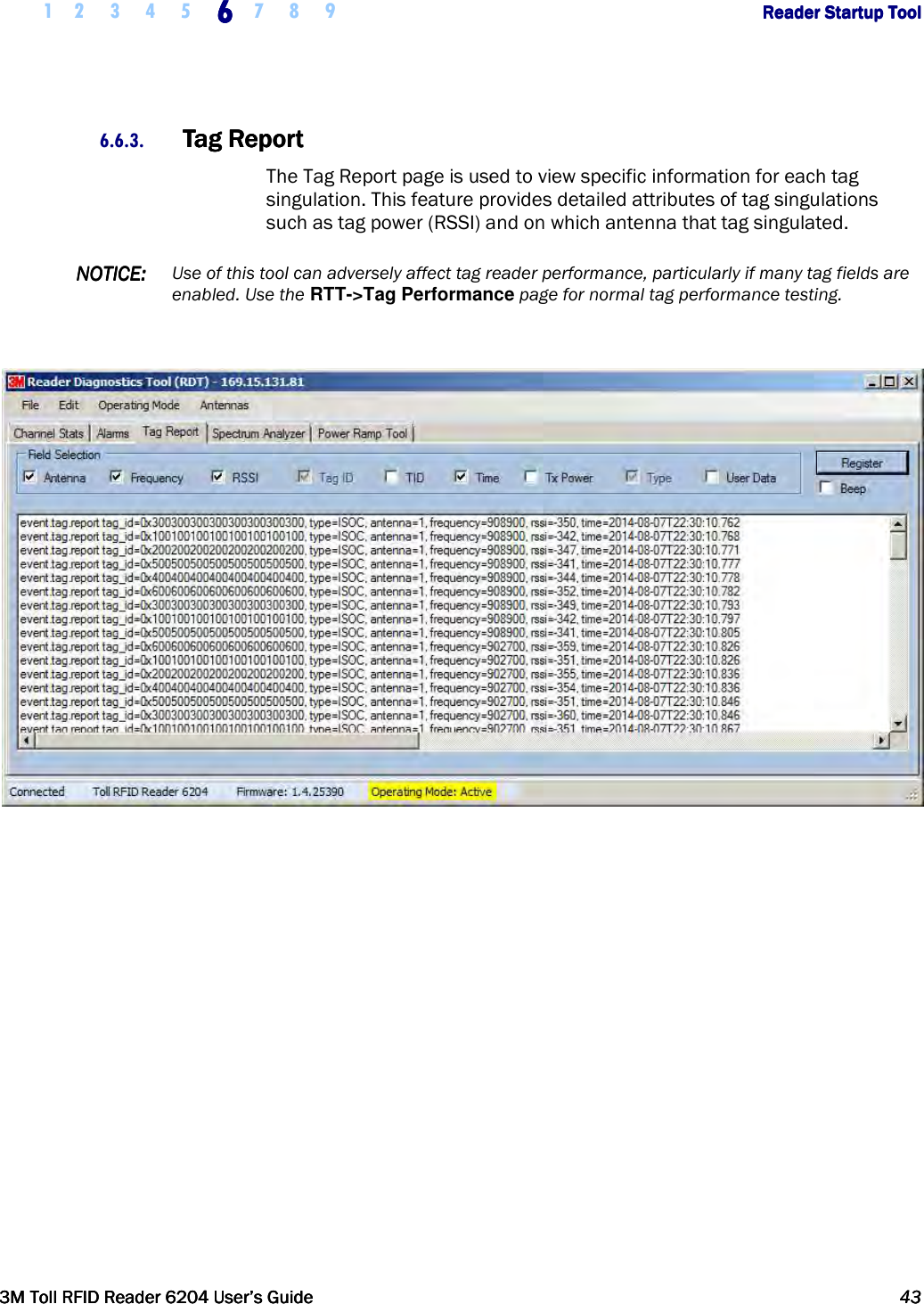
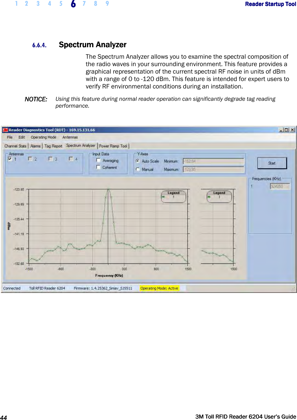
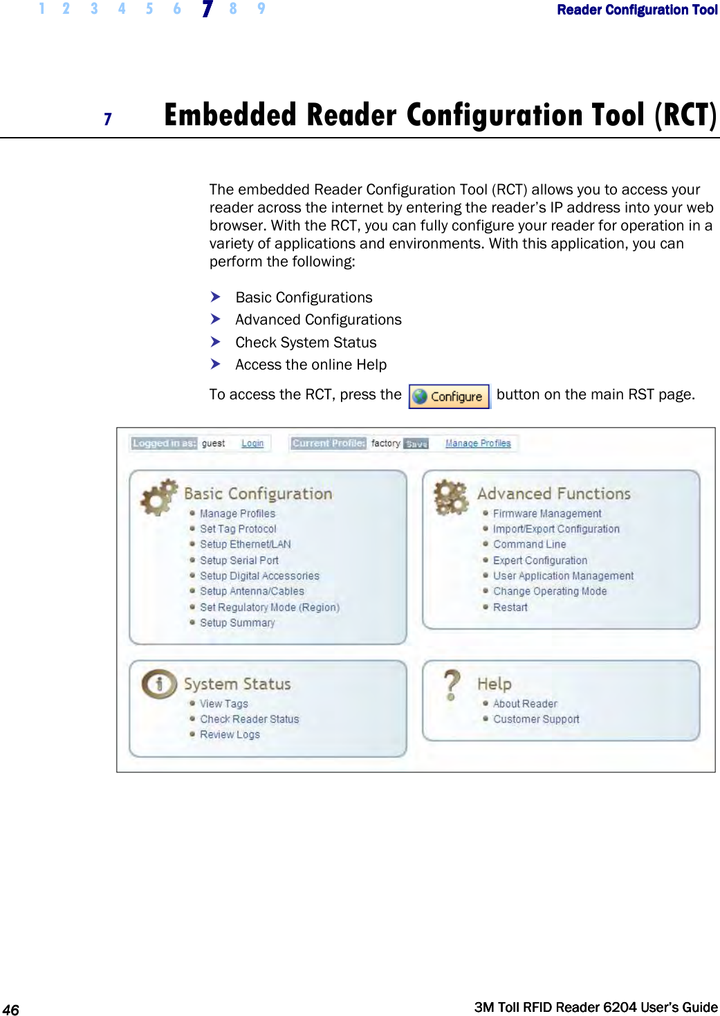
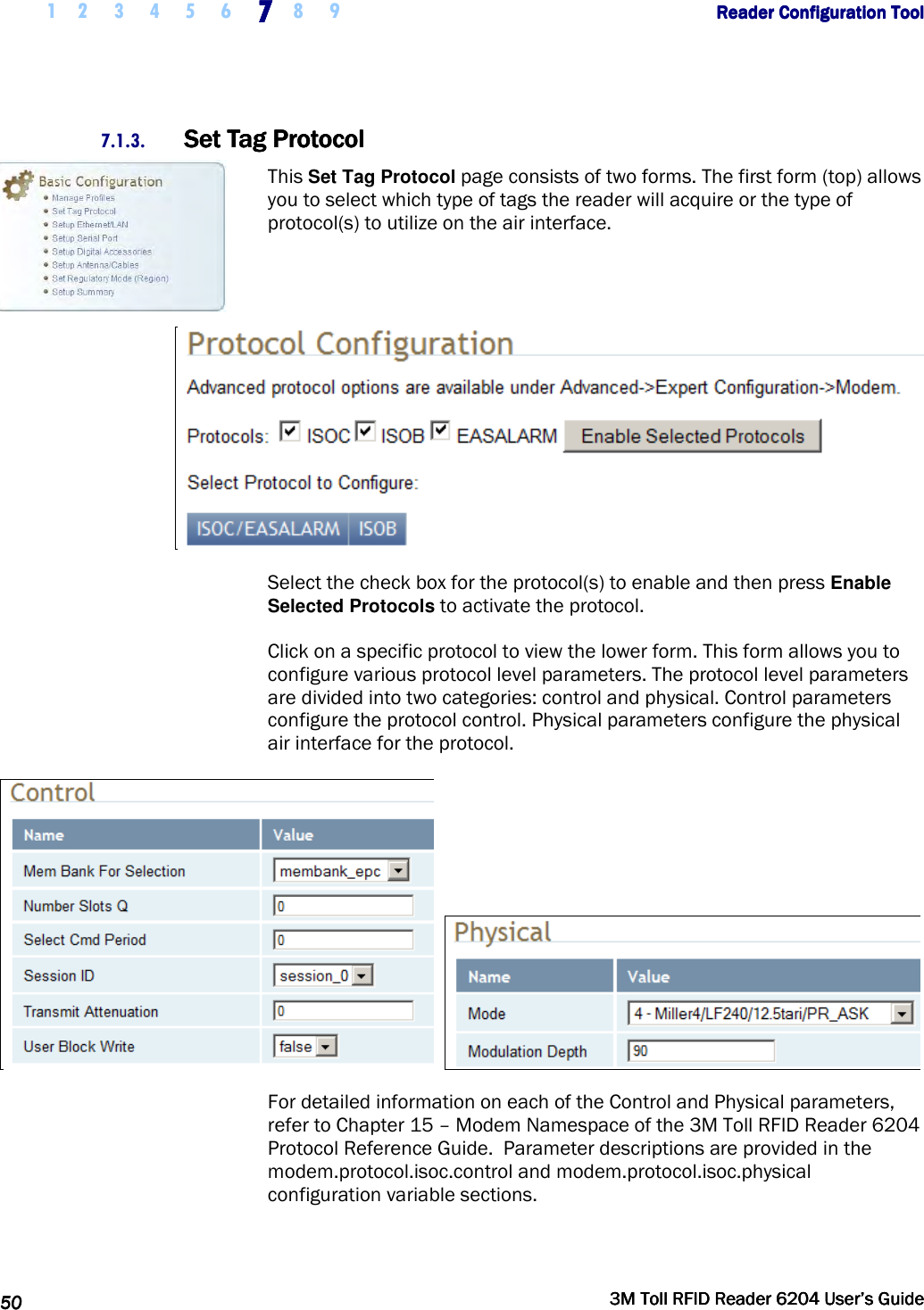
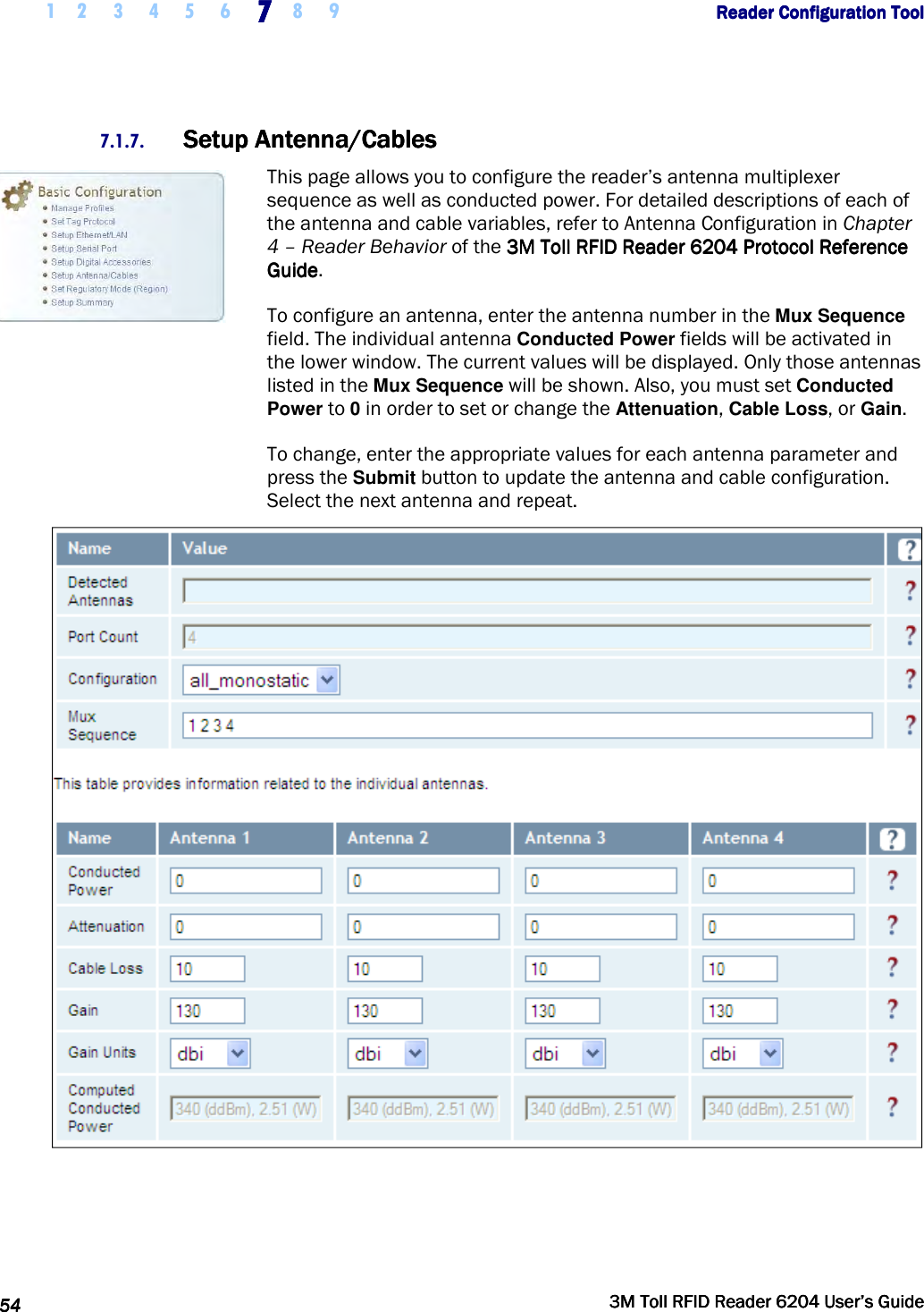
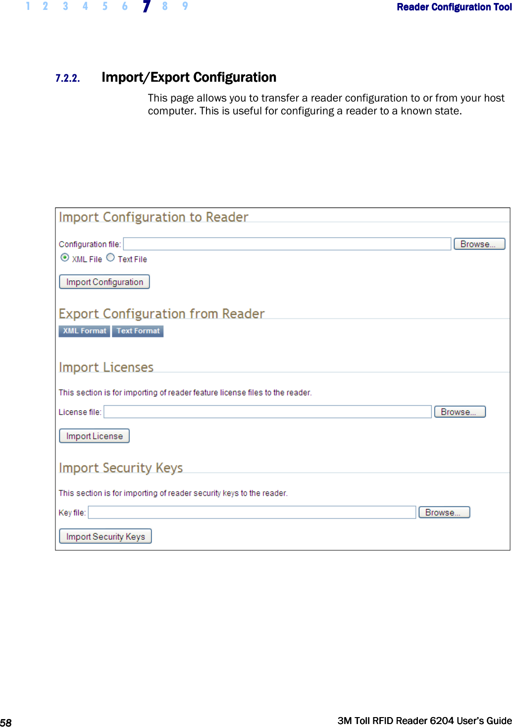
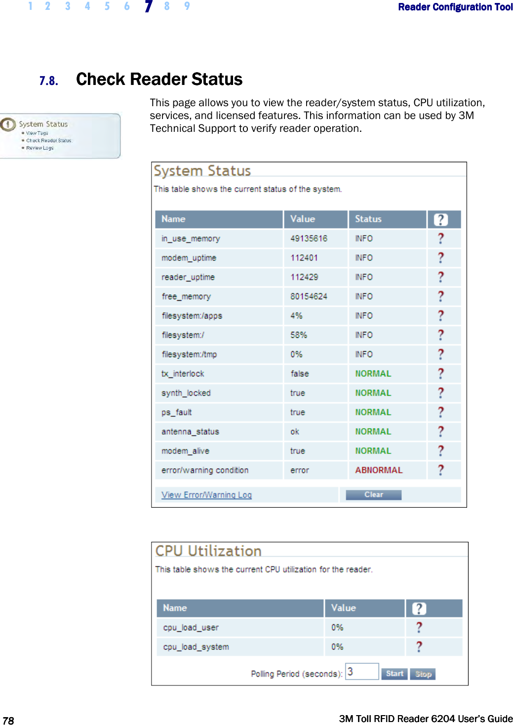
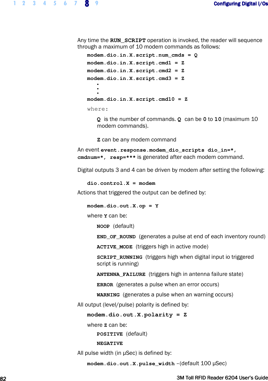
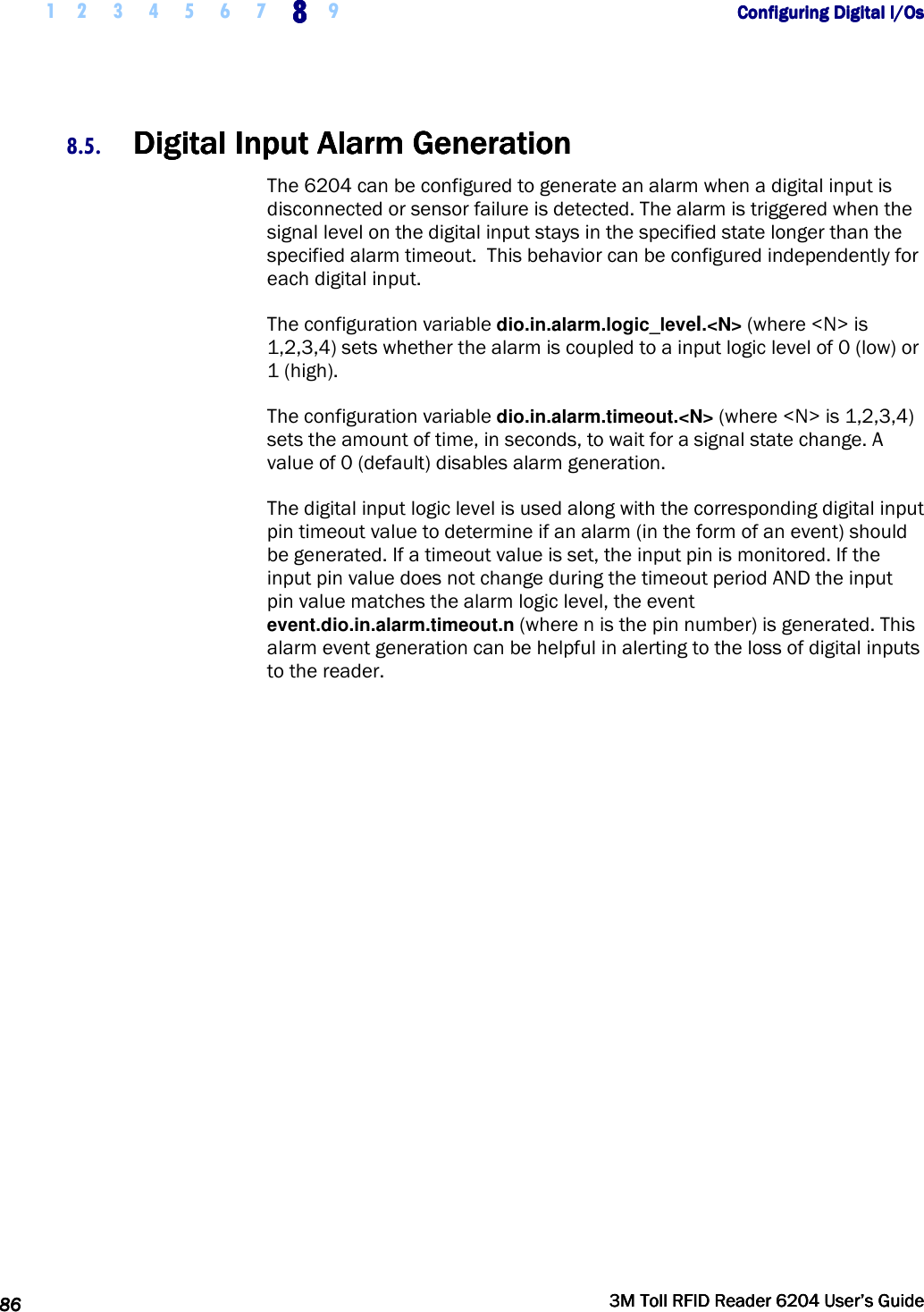
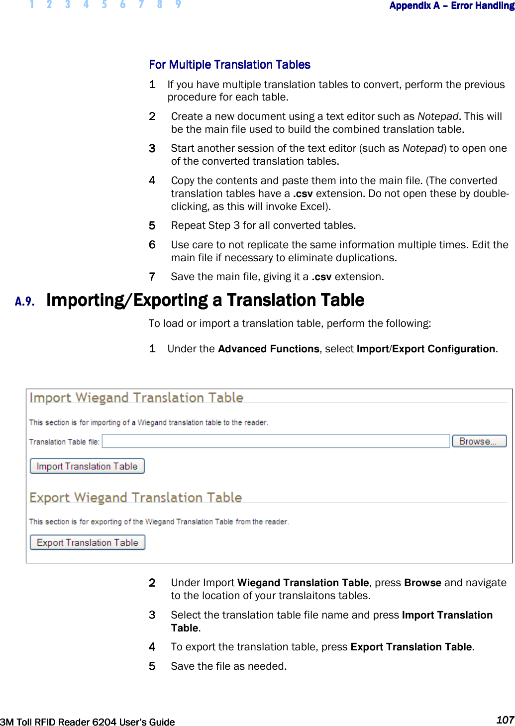
![1 2 3 4 5 6666 7 8 9 Reader Startup ToolReader Startup ToolReader Startup ToolReader Startup Tool 38383838 3M Toll RFID Reader 62043M Toll RFID Reader 62043M Toll RFID Reader 62043M Toll RFID Reader 6204 User’s GuideUser’s GuideUser’s GuideUser’s Guide Macro Macro Macro Macro Input subInput subInput subInput sub----windowwindowwindowwindow The Macro Input window shows the current script that will be sent to the reader when the Send to Reader button is selected. The text in the Macro Input window can be edited prior to being sent to the reader. Macro Output subMacro Output subMacro Output subMacro Output sub----windowwindowwindowwindow The Macro Output window is updated after the Send to Reader button is selected. Look at this window to verify that each command line in a script executed correctly. Look for the −−>> ok response from the reader for each command line. Macro Macro Macro Macro VariableVariableVariableVariablessss DiaDiaDiaDialog boxlog boxlog boxlog box When a macro is sent to the reader, the values for variables must be resolved via this Windows Dialog box. You can [tab] to each value field and enter the desired value. For example, one macro can be used for two different applications by using variables for antenna selection and transmit power. Macro ExampleMacro ExampleMacro ExampleMacro Example To configure the reader for FCC, Part 90 Dense operation, send the following macro (part90_6tari_lf640_PR_M2.mcr): # configure region setup.region=fcc setup.sub_region=fcc_part90 # set frequency setup.advanced.preferred_frequencies=915950 # configure protocol modem.protocol.isoc.control.auto_phy.enable=false modem.protocol.isoc.physical.set(tari=tari_06_25, return_link_freq=LF640, data_1_length=d1_len_20, rt_modulation=rt_mod_pr, tr_encoding=tr_enc_miller_2,interrogator_mode=dense)](https://usermanual.wiki/3M-Traffic-Safety-Systems/6204.User-manual/User-Guide-2464263-Page-50.png)
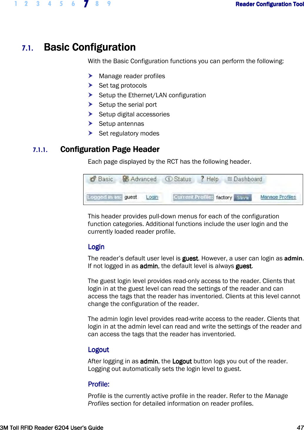
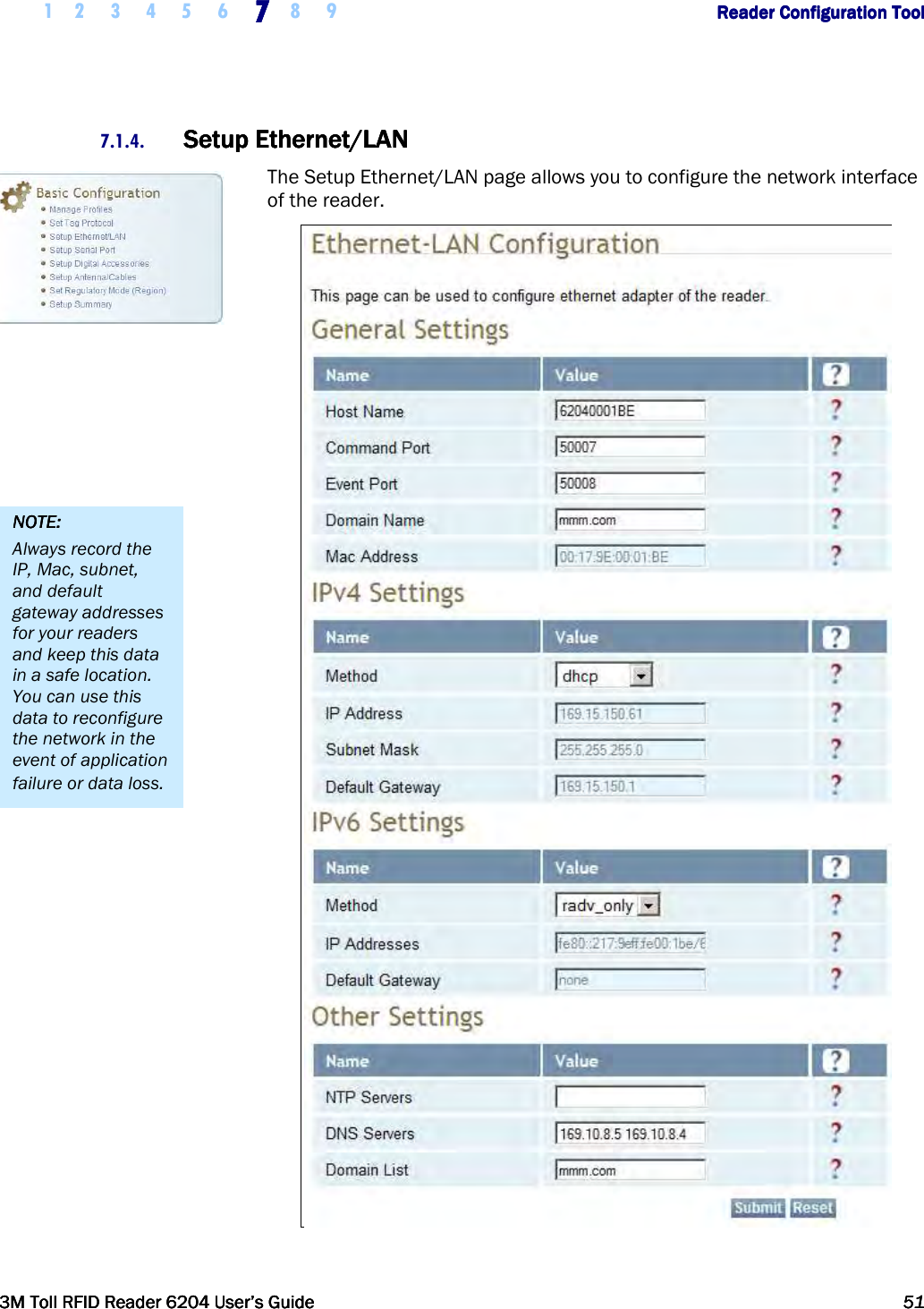
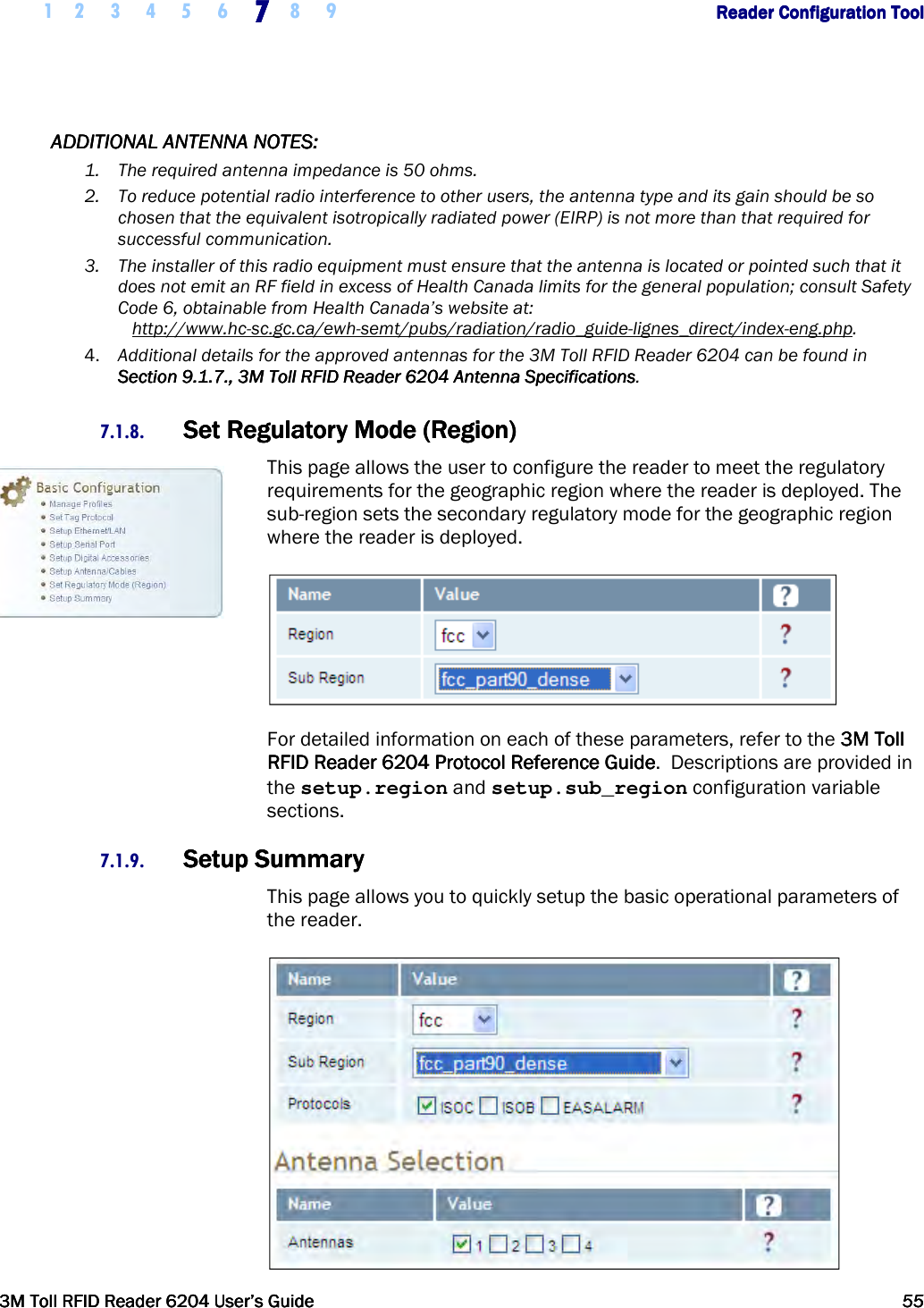
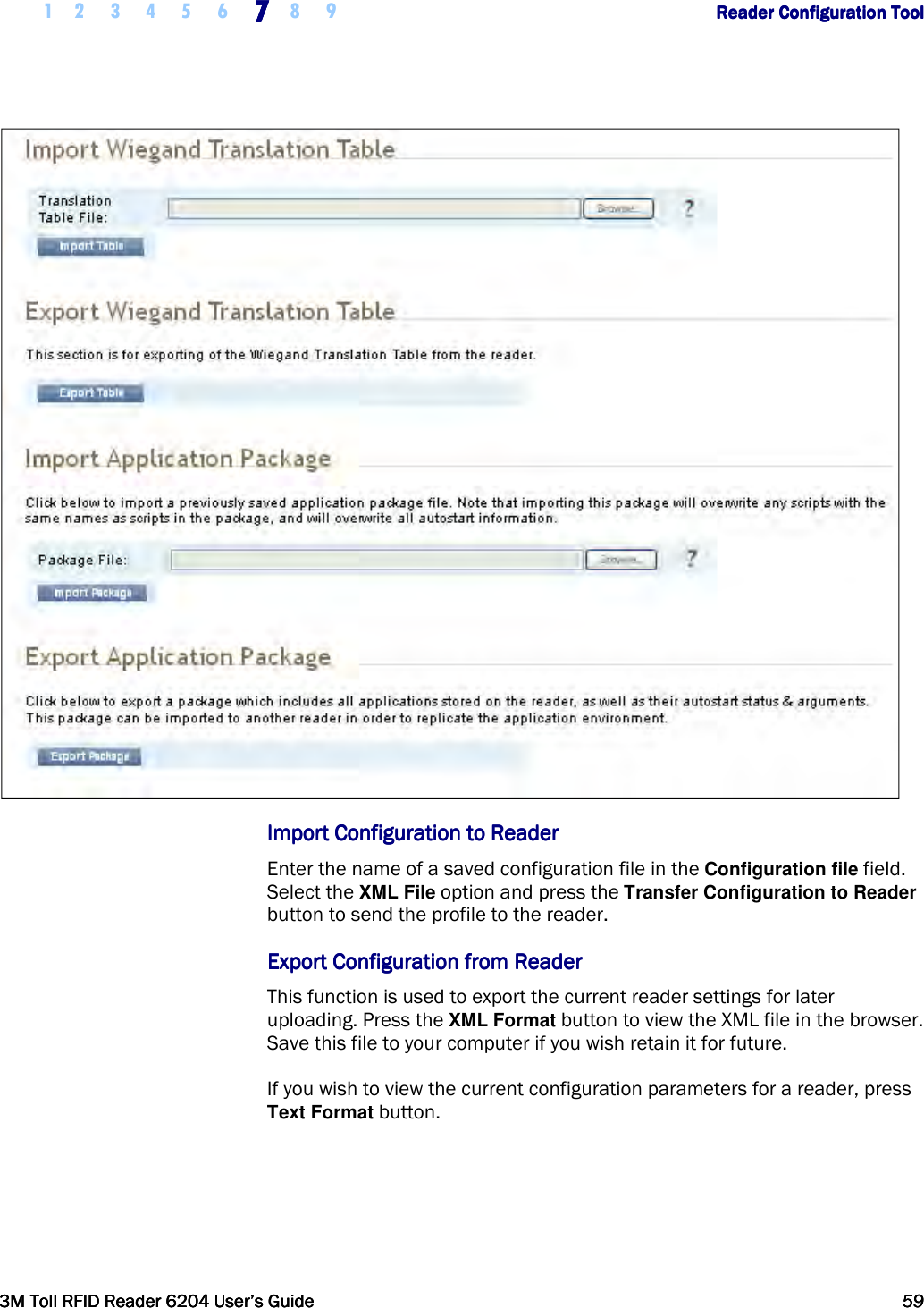
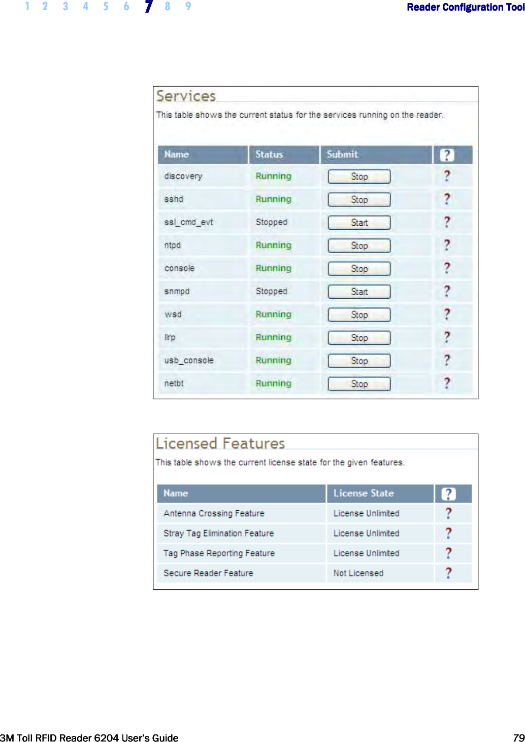
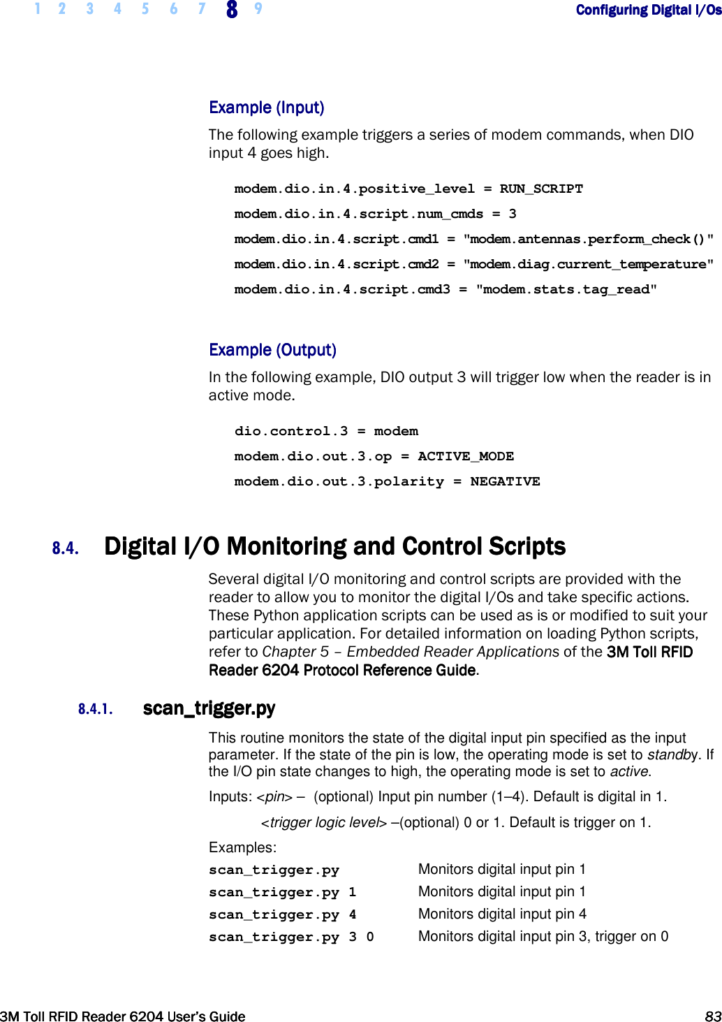
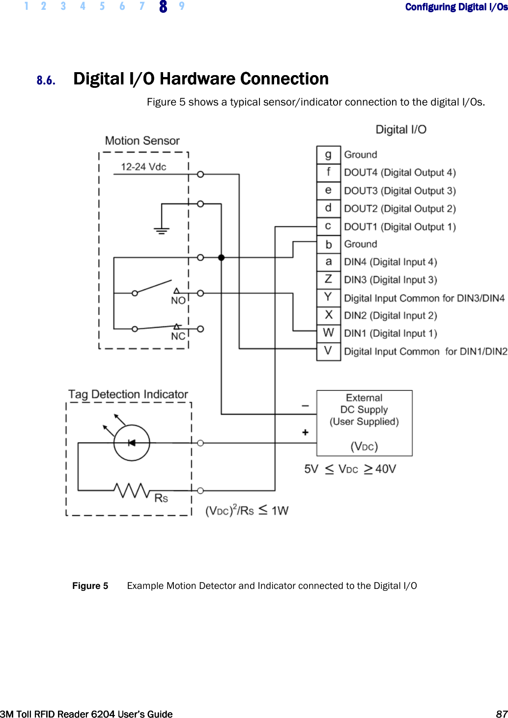

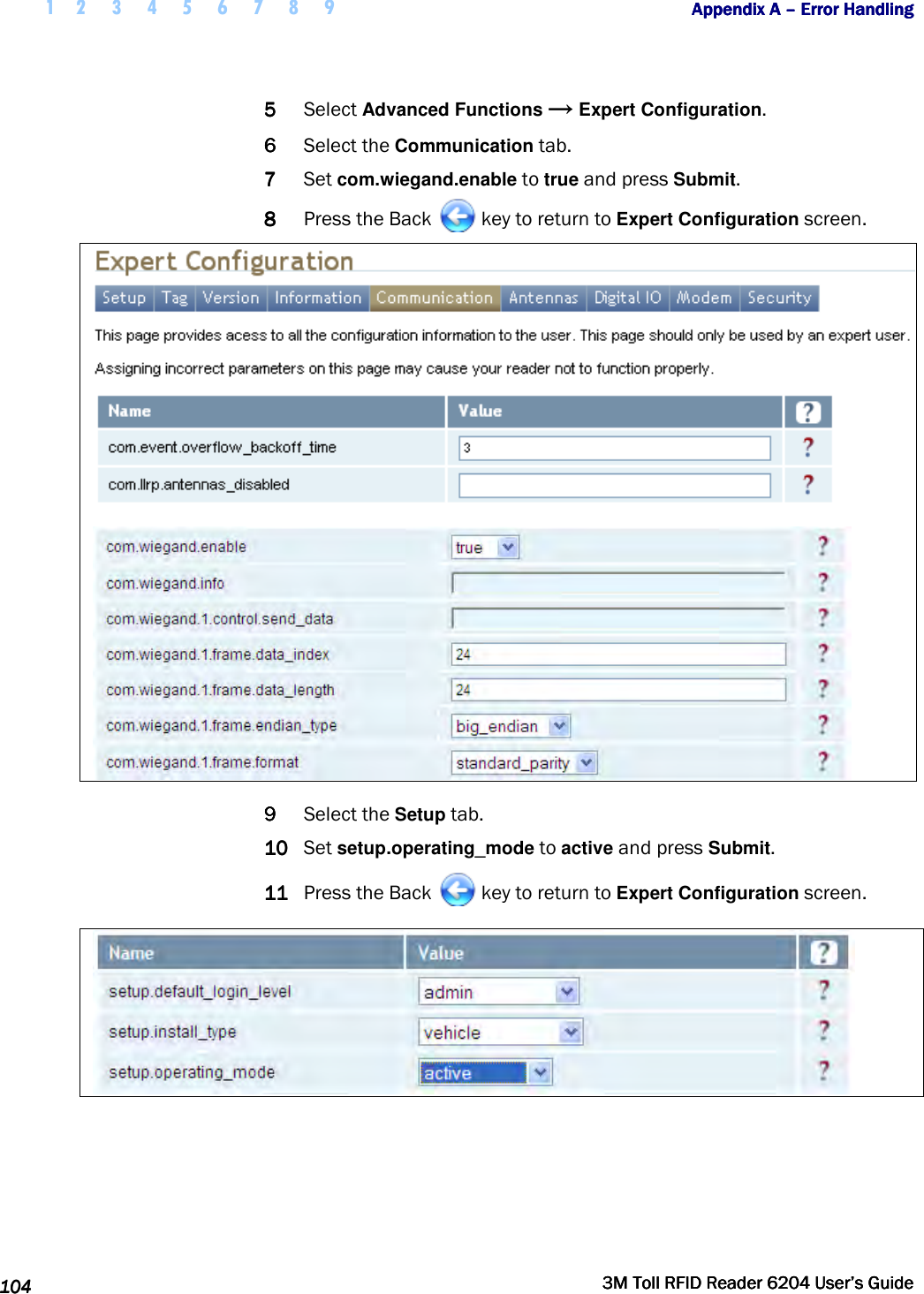
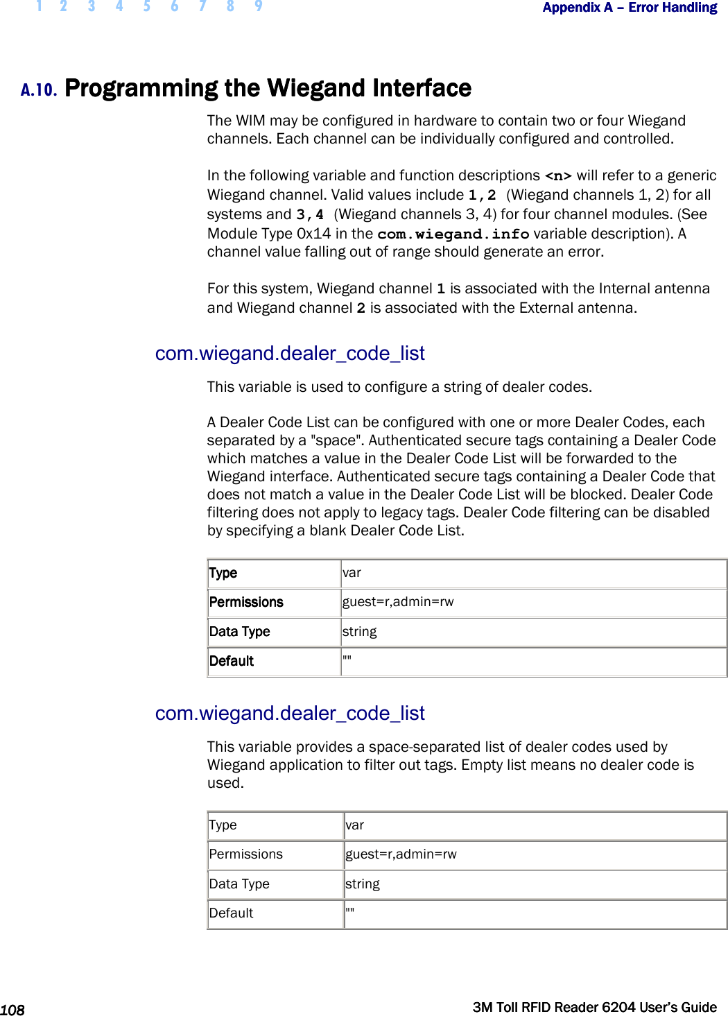
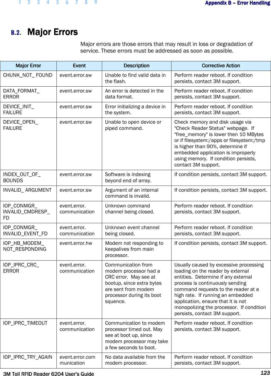
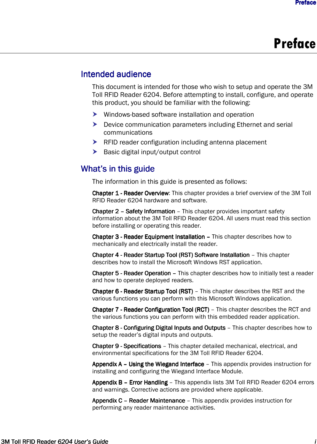
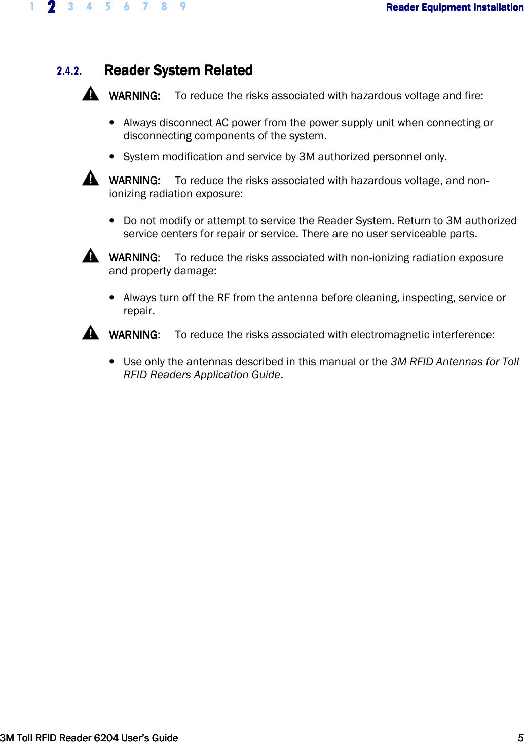
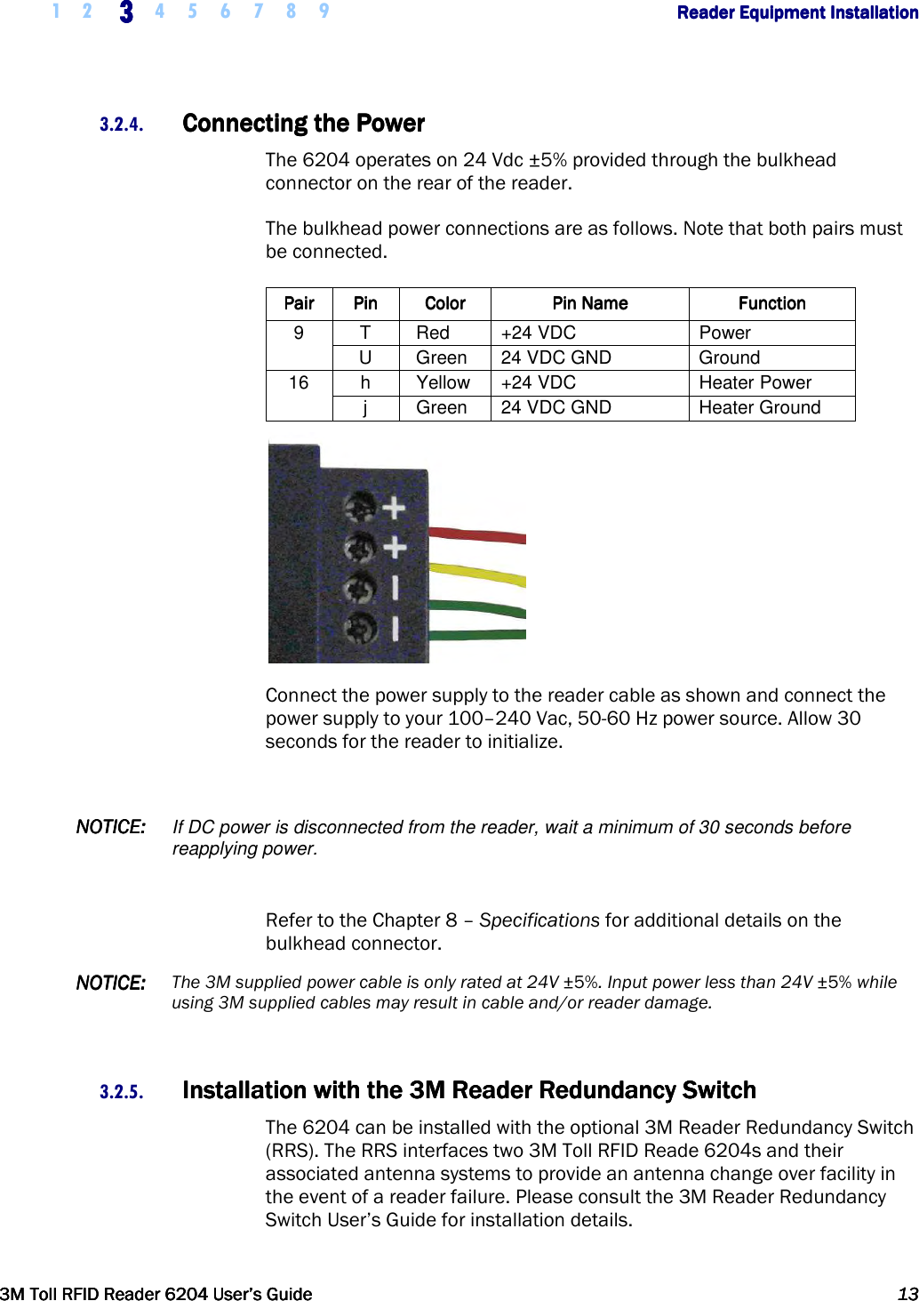
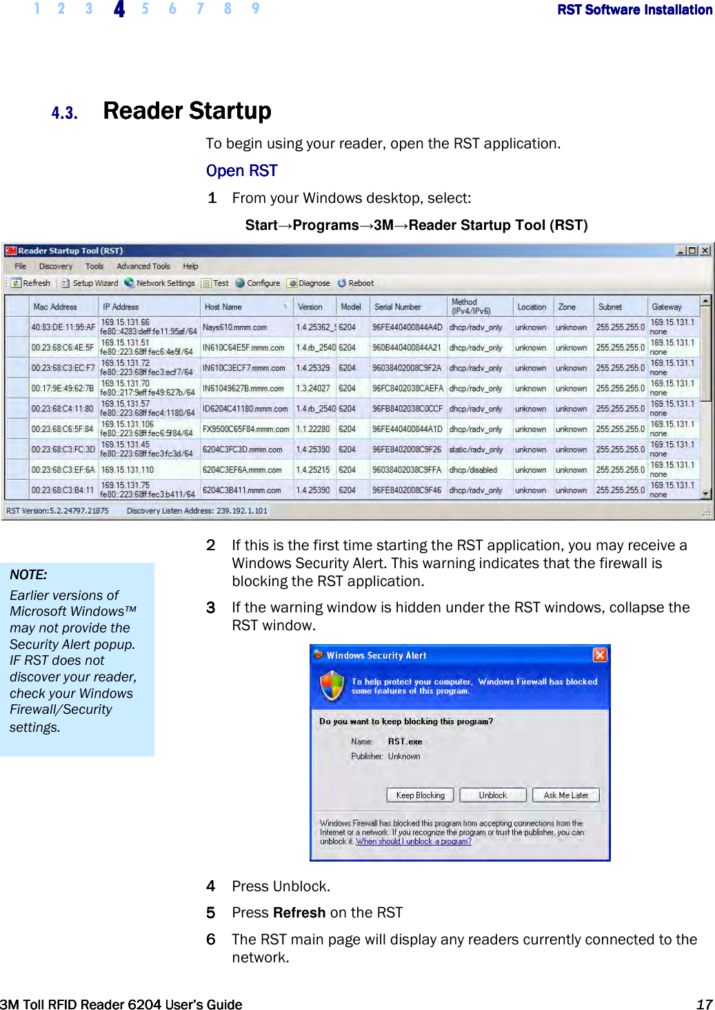
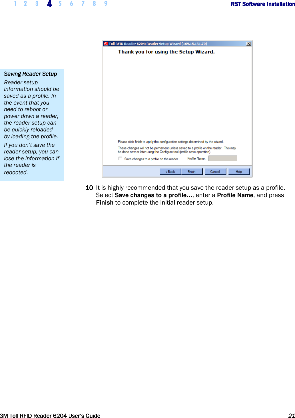
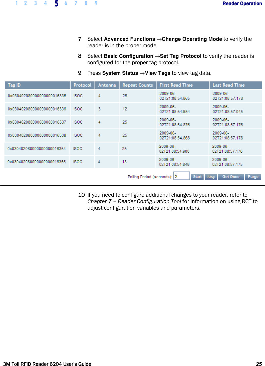
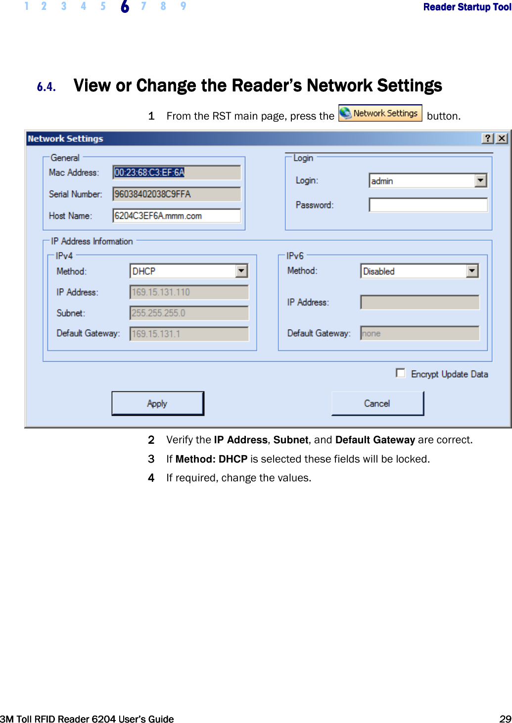
![1 2 3 4 5 6 7 8 9 Appendix A Appendix A Appendix A Appendix A –––– Error HandlingError HandlingError HandlingError Handling 3M Toll RFID Reader 62043M Toll RFID Reader 62043M Toll RFID Reader 62043M Toll RFID Reader 6204 User’s GuideUser’s GuideUser’s GuideUser’s Guide 117117117117 A.11. Programming the Translation TableProgramming the Translation TableProgramming the Translation TableProgramming the Translation Table The 6204 has a translation table facility that allows a translation table to be imported into the reader. This facility serves three primary functions: Support the use of legacy tags. Manage exceptions, such as the black-listing of tags. Serve as the list of allowed (and/or black-listed) tags for a standalone access control system (See Standalone Reader Operation Application Note). A.11.1. Translation Table Format The translation table uses a comma-separated variable (csv) format and will typically have a .csv extension. The first line of the file must contain the version number of the file format. Currently the file format version is 1.0. The second line of the file may optionally contain a string FC_LEN=X,SNR_LEN=Y, where X and Y are the facility code and serial number bit lengths respectively. If present, this line indicates how any decimal translated IDs in the rest of the file shall be interpreted (i.e. how many bits are represented by each field). If not present, a facility code length of 8 bits and a serial number length of 16 bits is assumed. Note that currently the web interface (RCT) does not generate this optional line, so any web-entered decimal Wiegand data assumes these default bit field lengths. Each subsequent line of the file represents a sequence of tags and has the following format: [StartID],[TagType],[StartXlateID],[Entries],[Handler]<CR><LF> where: [StartID] is the first tag ID of a sequence of tag IDs. In most cases, this is a hexadecimal number, preceded by 0x. If the tag protocol is configured to display tag IDs in 6 bit ASCII format, this is the ASCII string representing the starting tag ID. In the ASCII tag case, this is typically a 4 letter identifier followed by a 8 digit decimal number. [TagType] is the tag protocol type. This must be one of the protocols supported by the reader, for example, ISOC or ISOB. [StartXlateID] is the first translated ID of a sequence of translated IDs. The number is preceded by 0x. This value may be in hexadecimal format (if preceded by 0x), or in decimal format with facility code and serial number separated by a dash (i.e. "123-4567"). [Entries] is presented as a decimal number representing the number of tags in the sequence. Note: Maximum Number of Note: Maximum Number of Note: Maximum Number of Note: Maximum Number of FC and SNR ValuesFC and SNR ValuesFC and SNR ValuesFC and SNR Values When populating the translation table, specify only values that can be expressed in the number of bits used for Facility Code (FC) and Serial Number (SNR). For example, if 16 bit serial numbers are used, then only serial numbers in the range of 0 through 65535 should be specified in the table.](https://usermanual.wiki/3M-Traffic-Safety-Systems/6204.User-manual/User-Guide-2464263-Page-129.png)
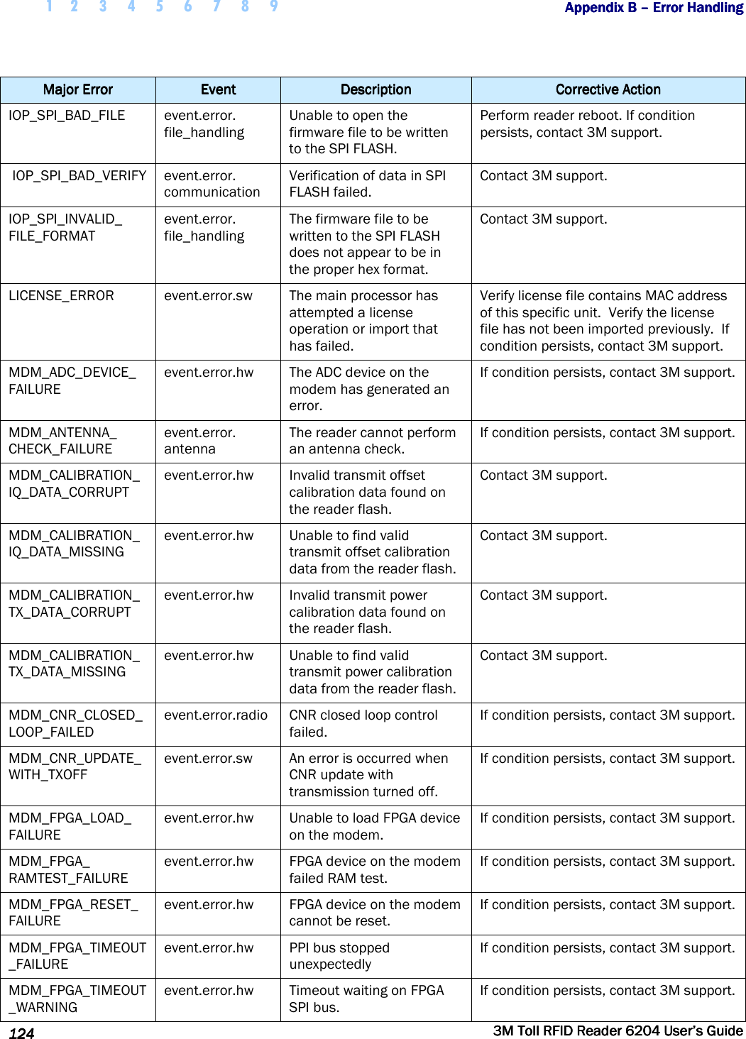
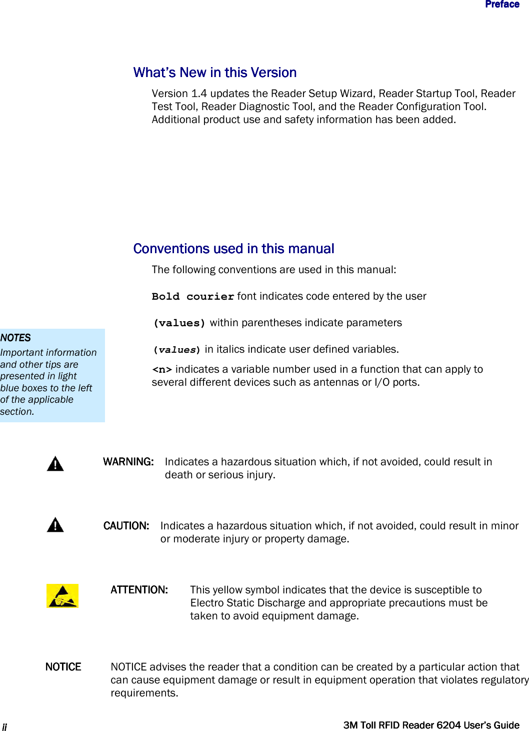
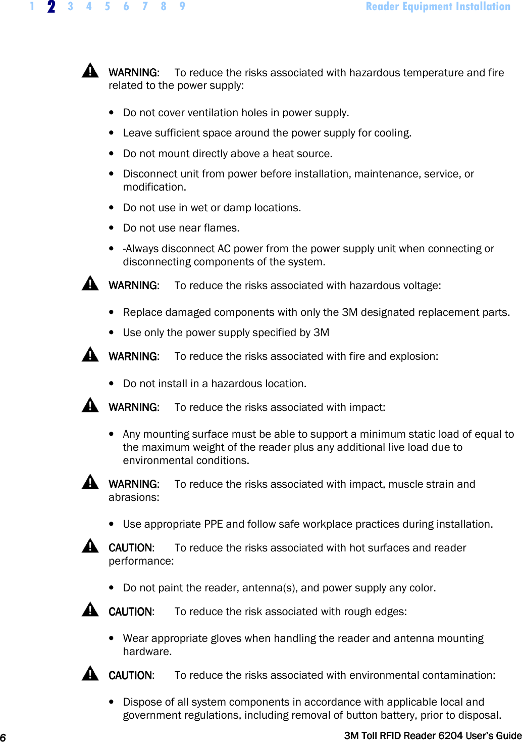
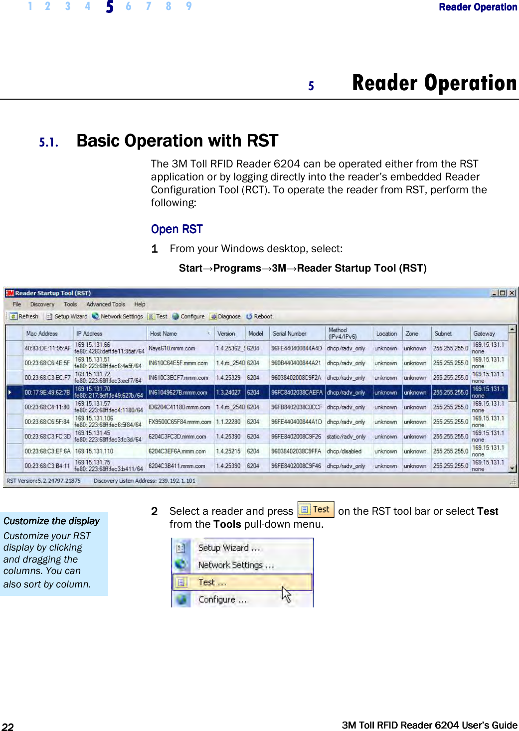
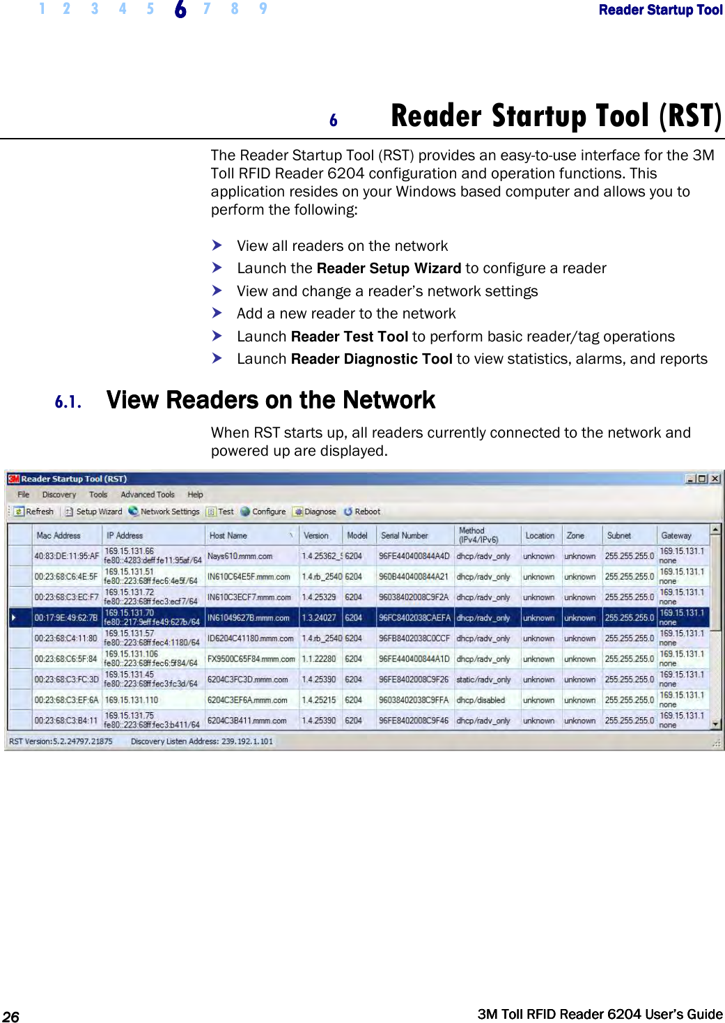
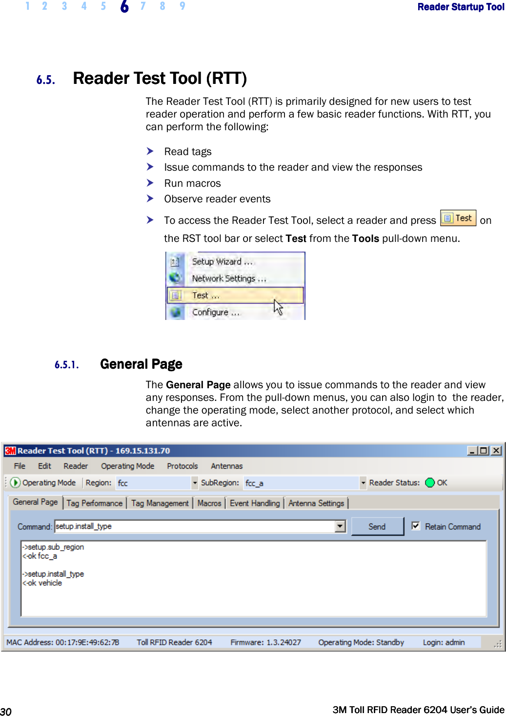
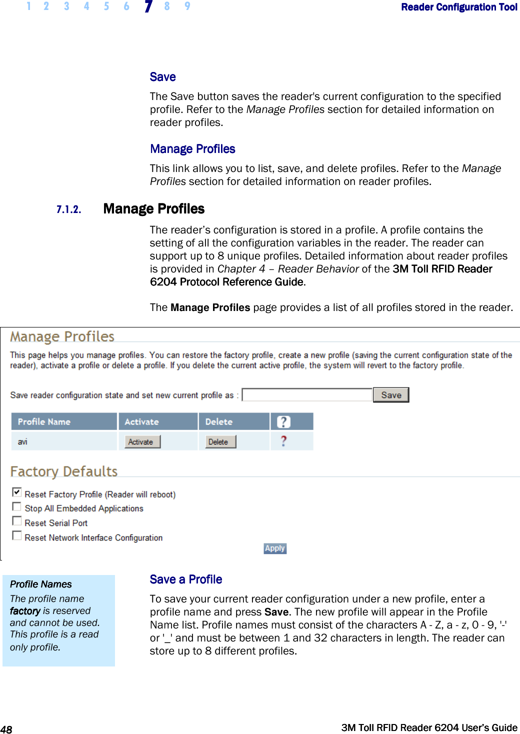
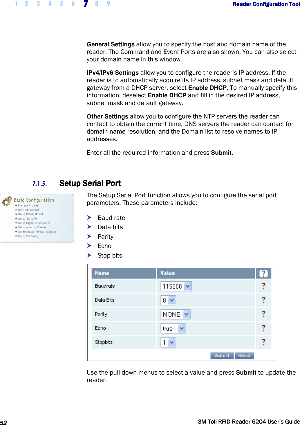
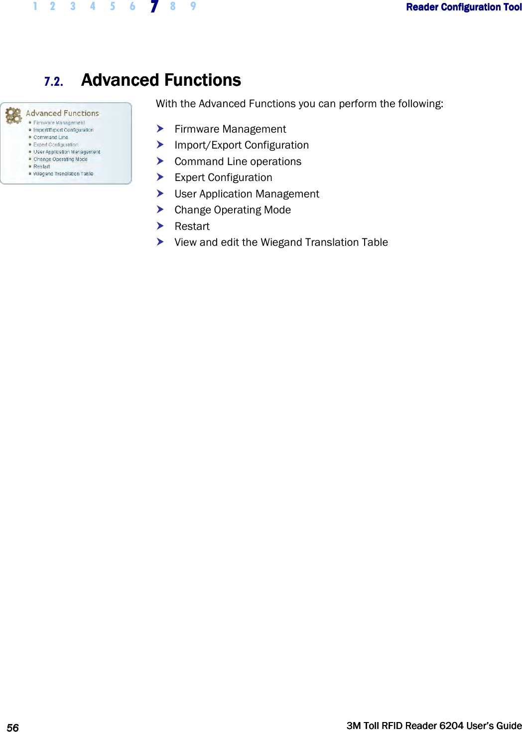
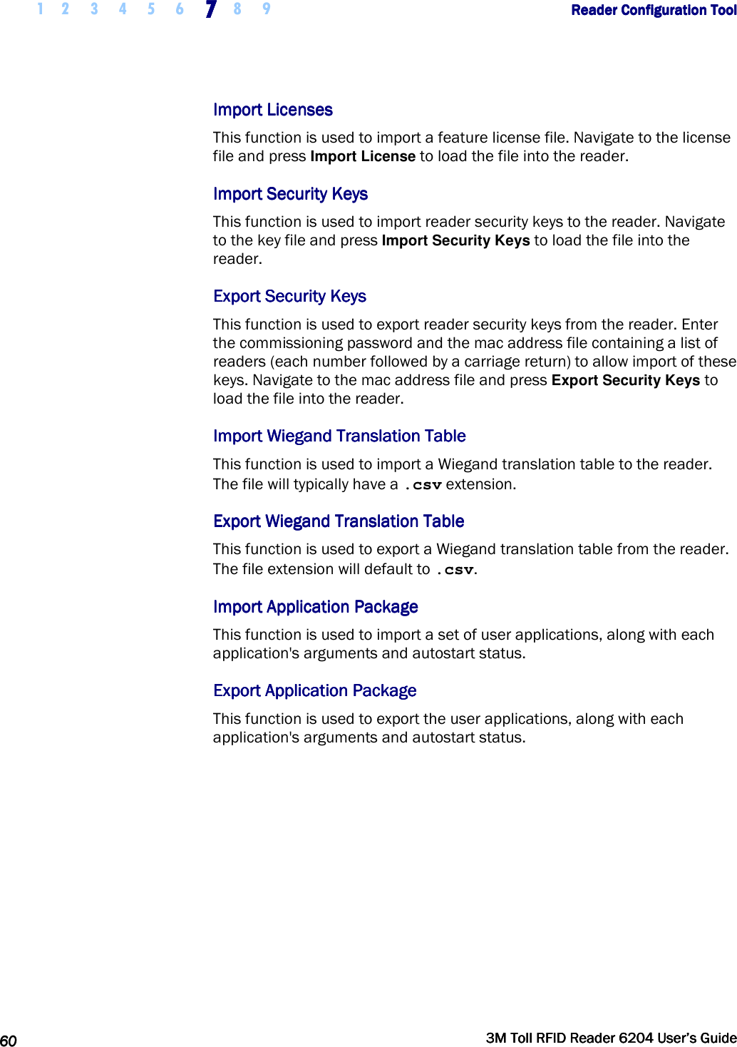
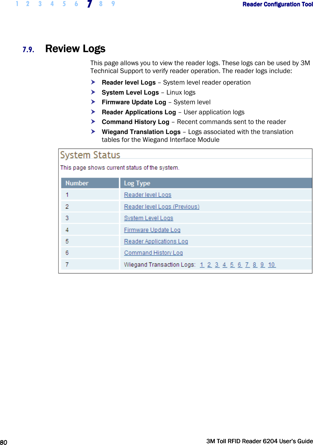
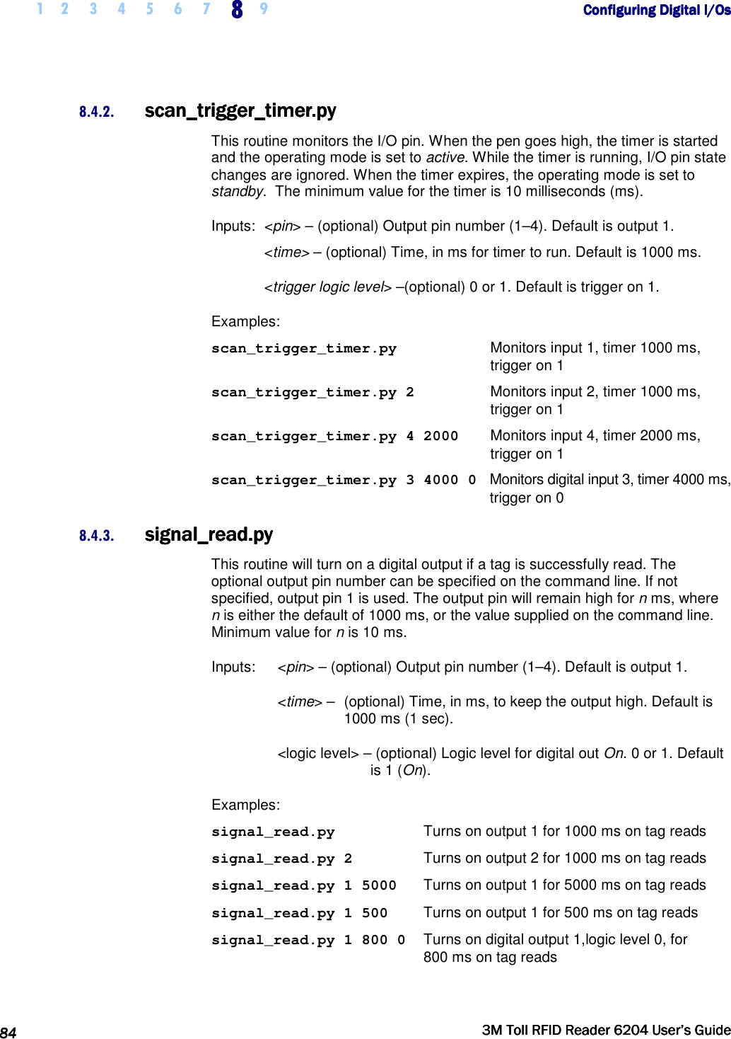
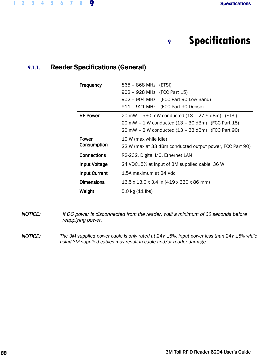
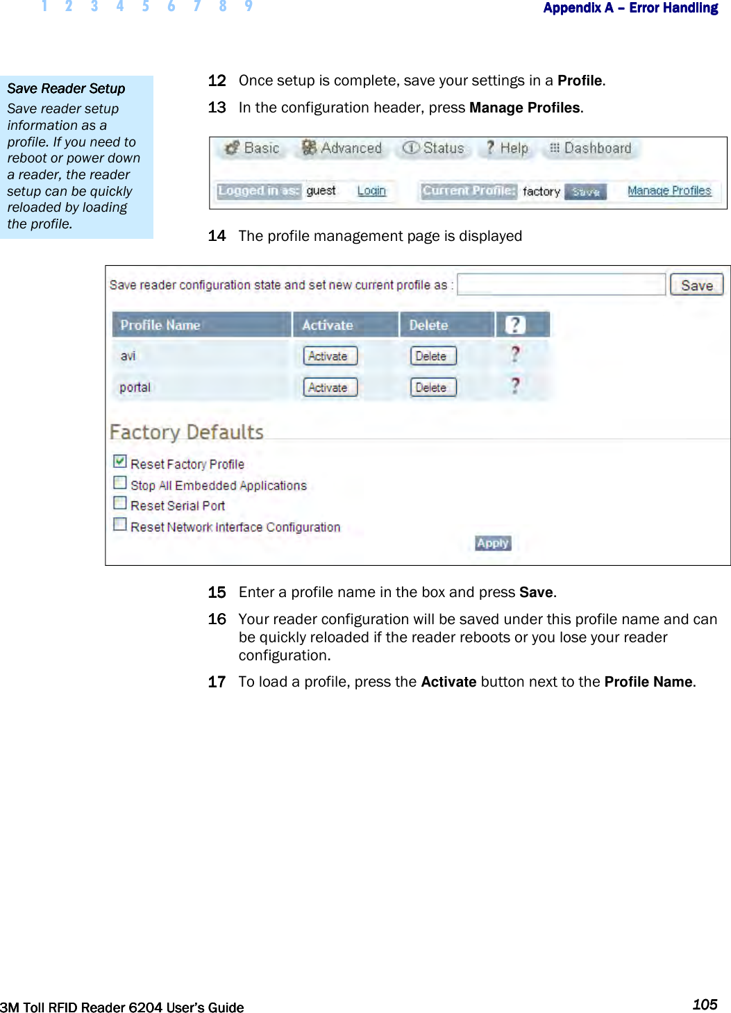
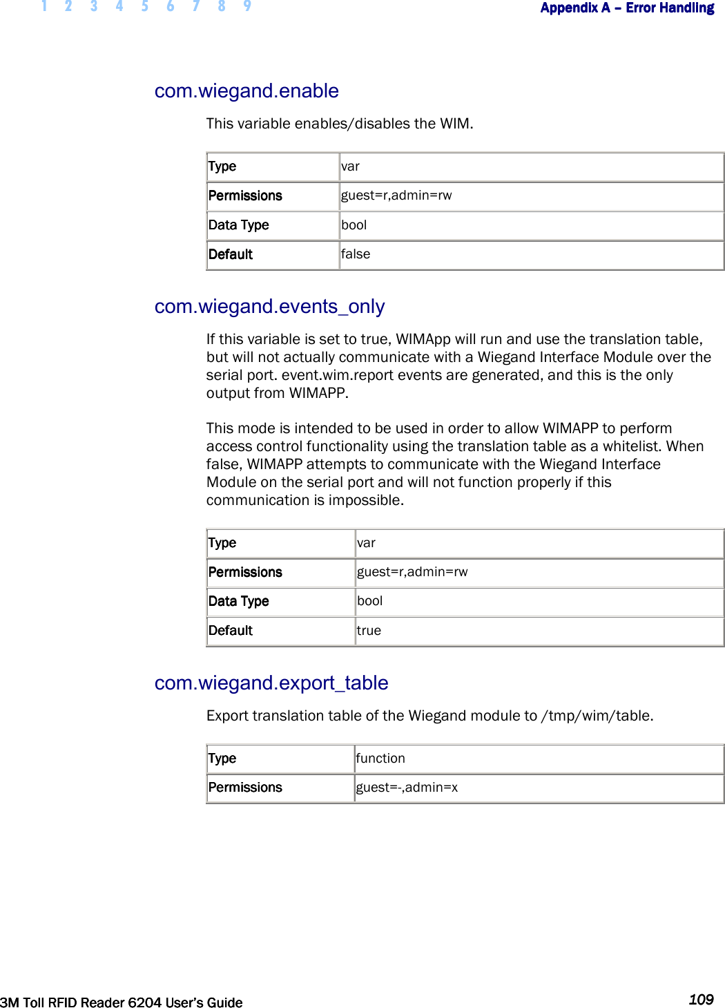
![1 2 3 4 5 6 7 8 9 Appendix A Appendix A Appendix A Appendix A –––– Error HandlingError HandlingError HandlingError Handling 118118118118 3M Toll RFID Reader 62043M Toll RFID Reader 62043M Toll RFID Reader 62043M Toll RFID Reader 6204 User’s GuideUser’s GuideUser’s GuideUser’s Guide [Handler] determines how tag is processed and is a decimal number (between 0 and 255) that applies to all tags in the sequence. Where: Bit 7: Password Authentication Indicator 1 = Password Authenticated 0 = Not Password Authenticated Bit 6: Blacklist Indicator 1 = Blacklisted 0 = not Blacklisted Bit 5: TID Authentication Indicator 1 = TID Authenticated 0 = Not TID Authenticated Bit 4: RFU (0) Bit 3: RFU (0) Bit 2: RFU (0) Bit 1: RFU (0) Bit 0: Handler value 1 = Pass Translated ID to WIM 0 = Do not pass translated ID to WIM A.11.2. Typical Handler values 1 – Legacy tag whose data is to be passed through the system to the Wiegand interface (00000001b) 64 – Black-listed Legacy tag (01000000b). 33 – TID-Authenticated Tag whose data is to be passed through the system to the Wiegand interface (00100001b). 96 – Black-listed TID-Authenticated tag (01100000b). 129 – Password-Authenticated Tag whose data is to be passed through the system to the Wiegand interface (10000001b). 192 – Black-listed Password-Authenticated tag (11000000b). A.11.3. Example Table Entry The following is a typical translation table entry. 0x000000000000000000010000,ISOC, 0x000A0100,1000,1<CR><LF> This entry indicates: 1000 ISOC protocol tags in the sequence Each with a handler value of 1 (legacy tag passed through system) Actual tag IDs range from 0x000000000000000000010000 to 0x0000000000000000000103E7 Corresponding translated IDs would range from 0x000A0100 to 0x000A04E7](https://usermanual.wiki/3M-Traffic-Safety-Systems/6204.User-manual/User-Guide-2464263-Page-130.png)
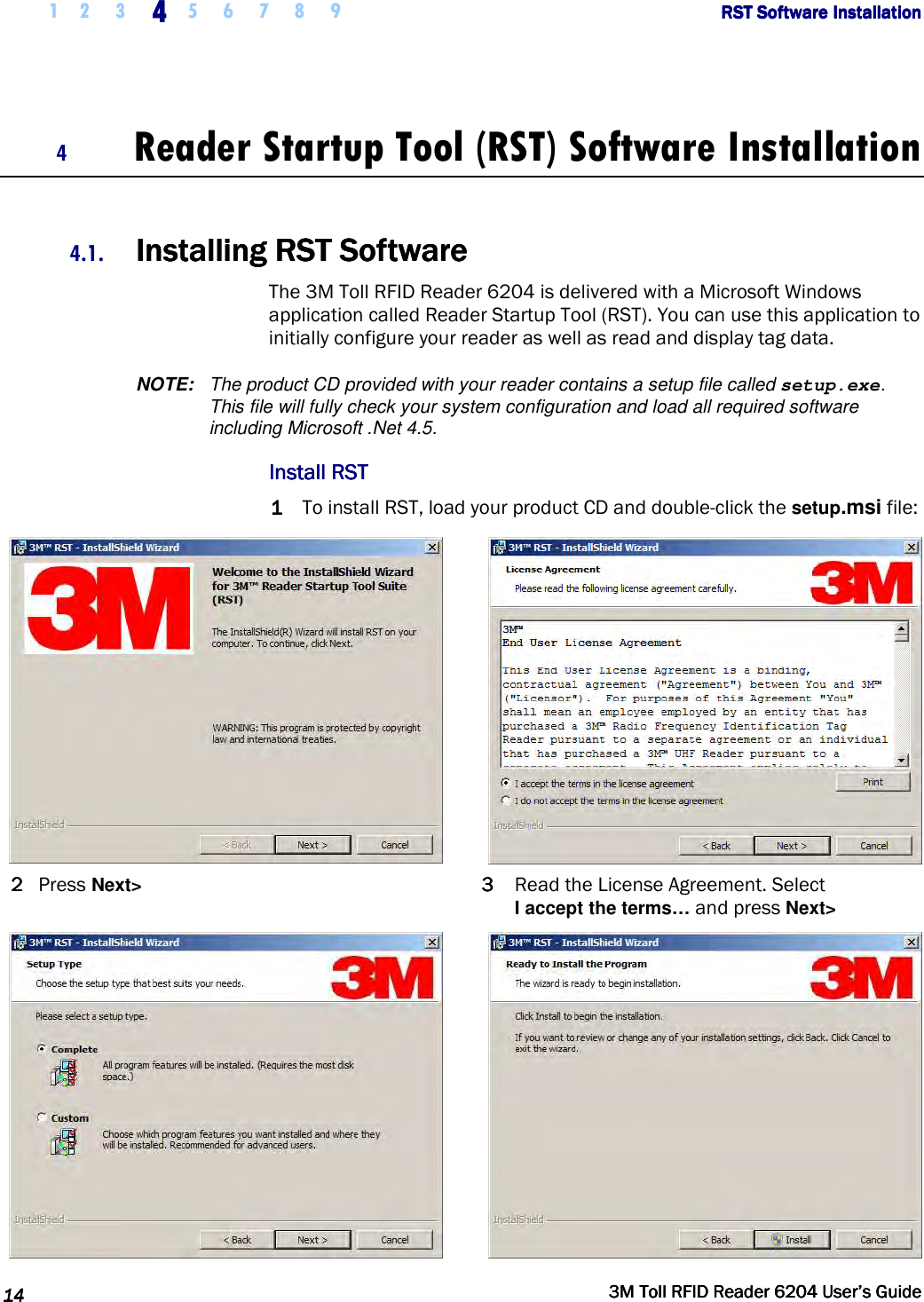
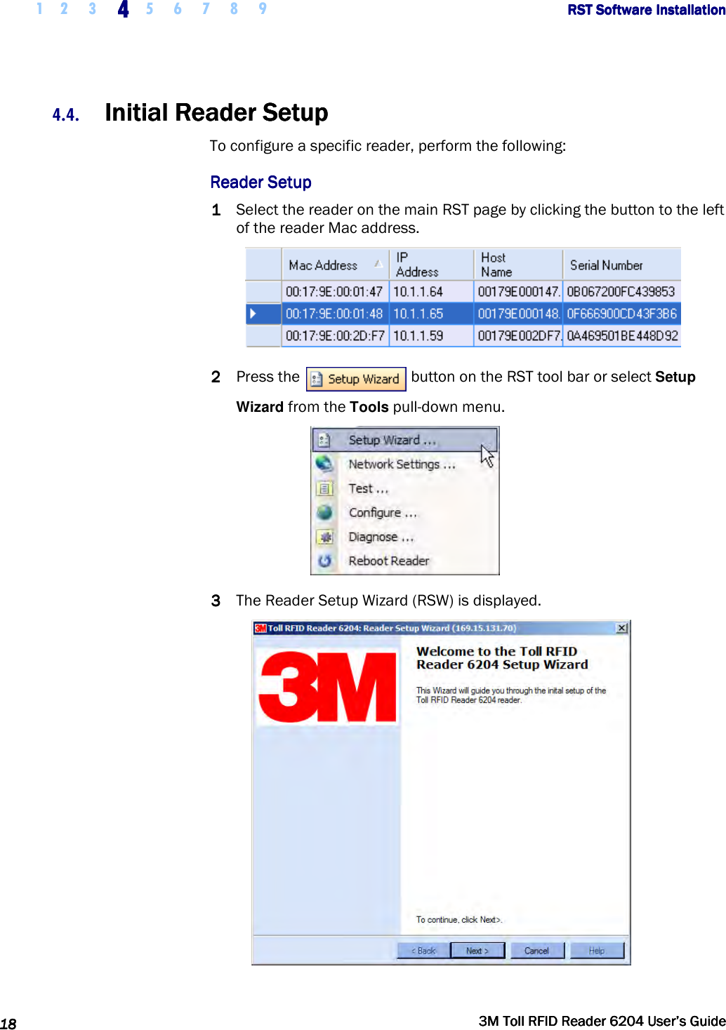
![1 2 3 4 5 6 7 8 9 Appendix A Appendix A Appendix A Appendix A –––– Error HandlingError HandlingError HandlingError Handling 120120120120 3M Toll RFID Reader 62043M Toll RFID Reader 62043M Toll RFID Reader 62043M Toll RFID Reader 6204 User’s GuideUser’s GuideUser’s GuideUser’s Guide A.13. Transaction LogTransaction LogTransaction LogTransaction Log A transaction log is used to record information on tag arrivals. Each entry in the log contains the following information:- [time] – provides the date and time of the tag arrival. [tag_id] – ID of the tag. [antenna] – states the antenna where the tag was read. [handle] – 8-bit values that provide information about a tag upon its arrival. The bit values are defined as: Bit 7 Password Authentication 1 = Password Authenticated 0 = Not Password Authenticated Bit 6 Blacklist Indicator 1 = Blacklisted 0 = Not Blacklisted Bit 5 TID-Authentication 1 = TID Authenticated 0 = Not TID Authenticated Bit 4 User Data Read Failure 1 = Failed To Read User Data 0 = User Data Read (for authenticated tag) (or) Not Applicable (for legacy tag) Bit 3 Dealer Code Mismatch 1 = Dealer Code Mismatch 0 = Dealer Code Match (for authenticated tag) (or) Not Applicable (for legacy tag) Bit 2 RFU Bit 1 RFU Bit 0 Wiegand Access 1 = Translated ID passed to Wiegand interface. 0 = No data passed to Wiegand interface. [type] – tag protocol type [translated_id] – hexadecimal value of the translated tag ID (result of the translation table lookup).](https://usermanual.wiki/3M-Traffic-Safety-Systems/6204.User-manual/User-Guide-2464263-Page-132.png)