ABB POWER TECHNOLOGY 440914A Handheld Data Transceiver User Manual 2501en A5 EXCOUNT II Transceiver manual indd
ABB POWER TECHNOLOGY PRODUCTS AB Handheld Data Transceiver 2501en A5 EXCOUNT II Transceiver manual indd
Contents
- 1. Users manual
- 2. revised page 2 of manual
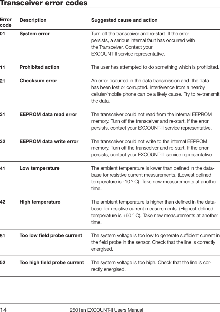
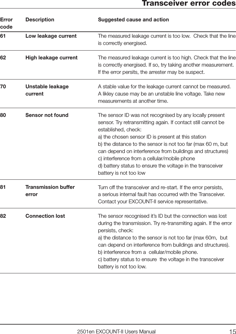
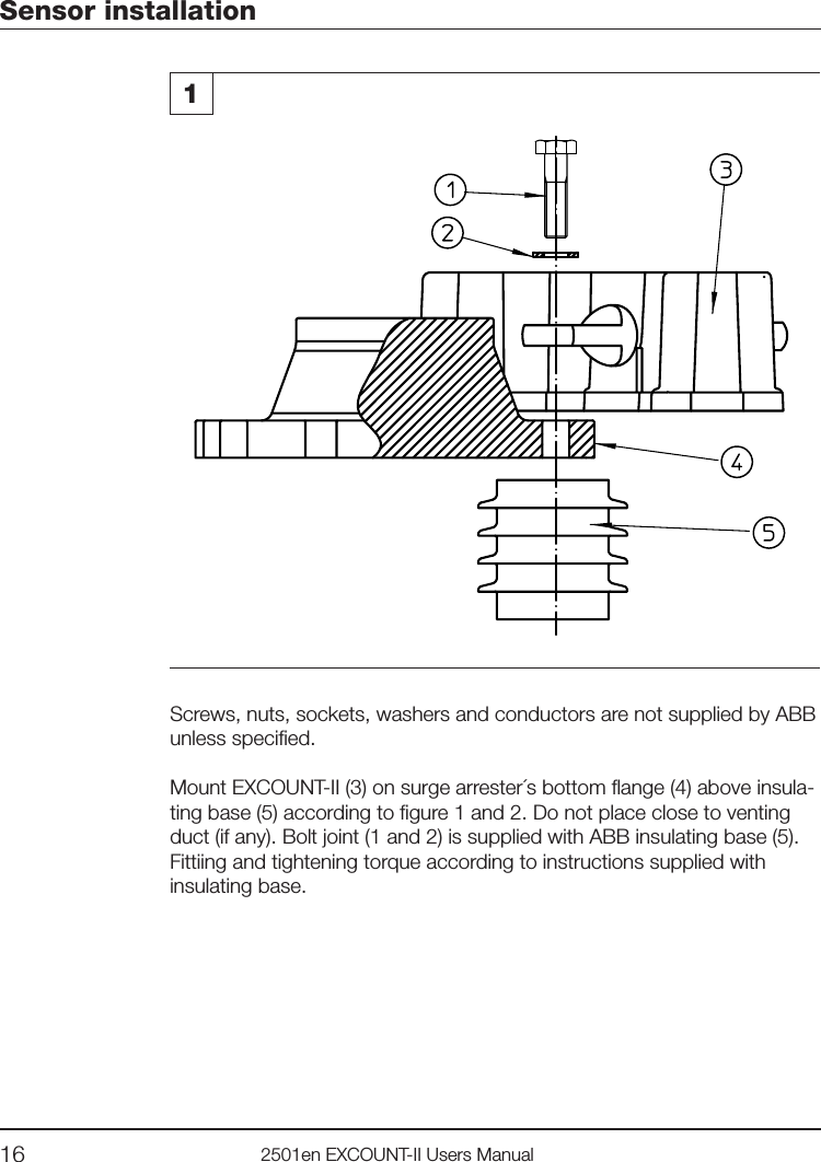
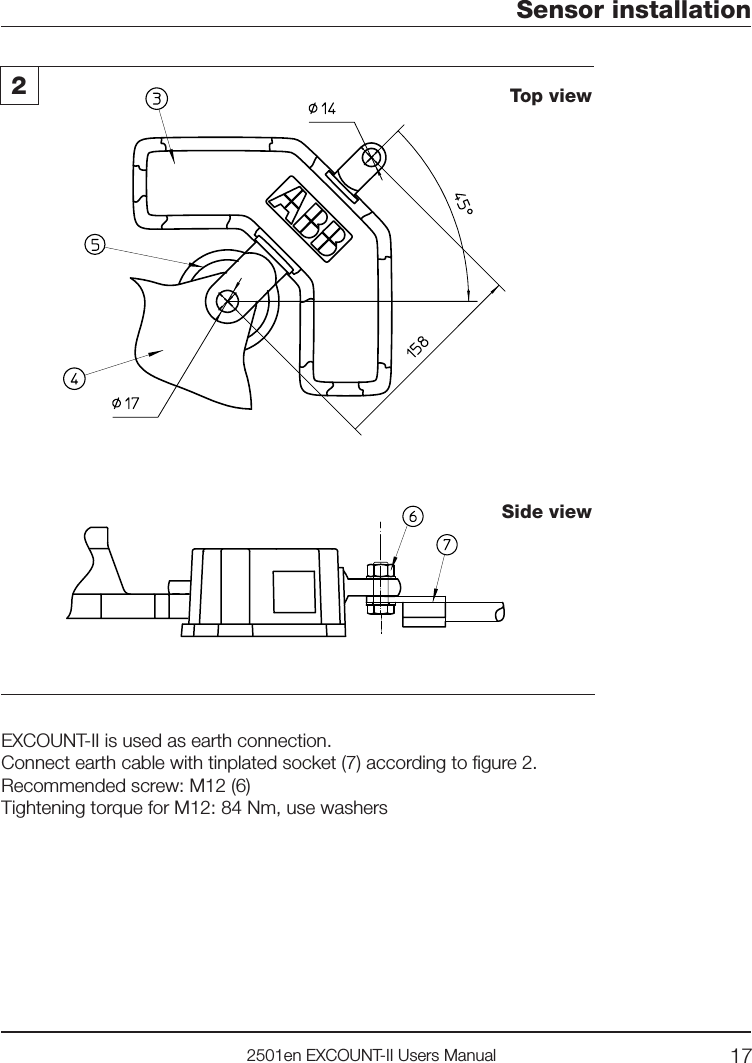
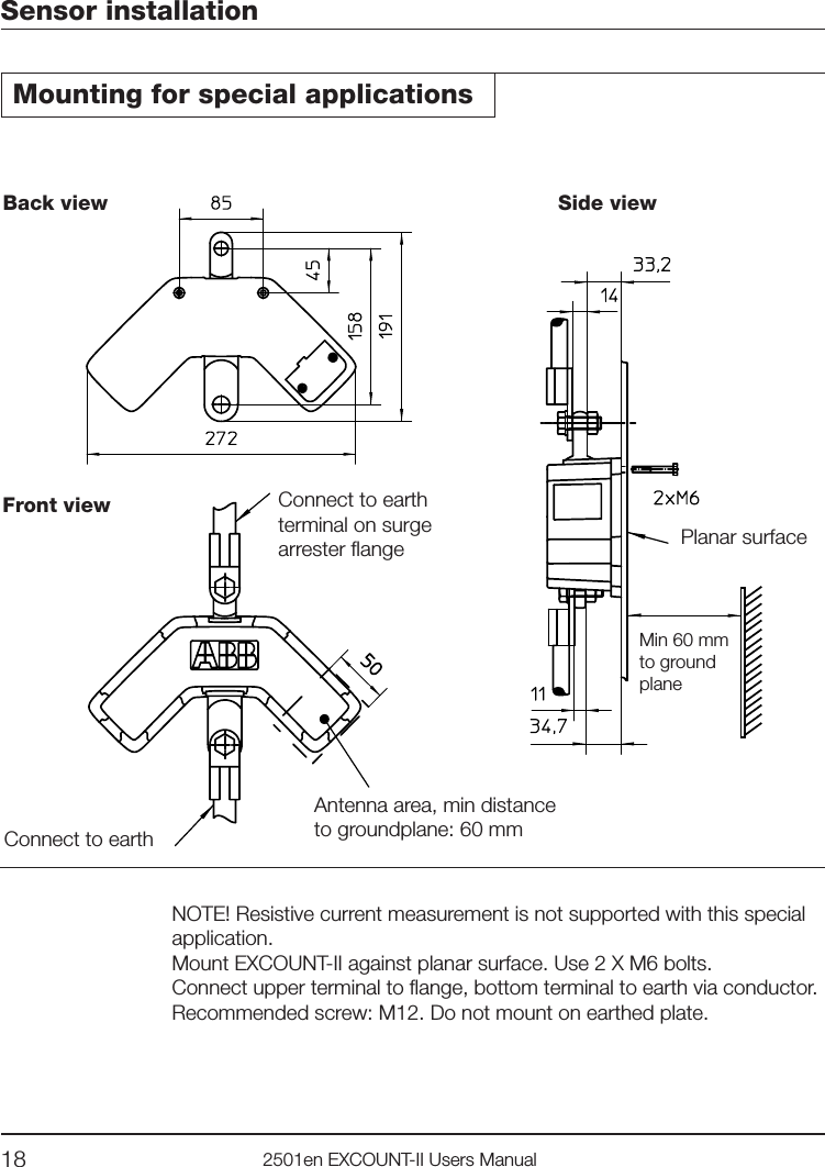
Users manual