ABIOMED 0042-4000 IMC, Impella Controller User Manual
ABIOMED Inc. IMC, Impella Controller Users Manual
UserManual.wiki
>
ABIOMED
>
0042 4000 User Manual
Users Manual
Navigation menu
Upload a User Manual
Namespaces
Wiki Guide
HTML
PDF
Info
Views
User Manual
Discussion / Help
Navigation


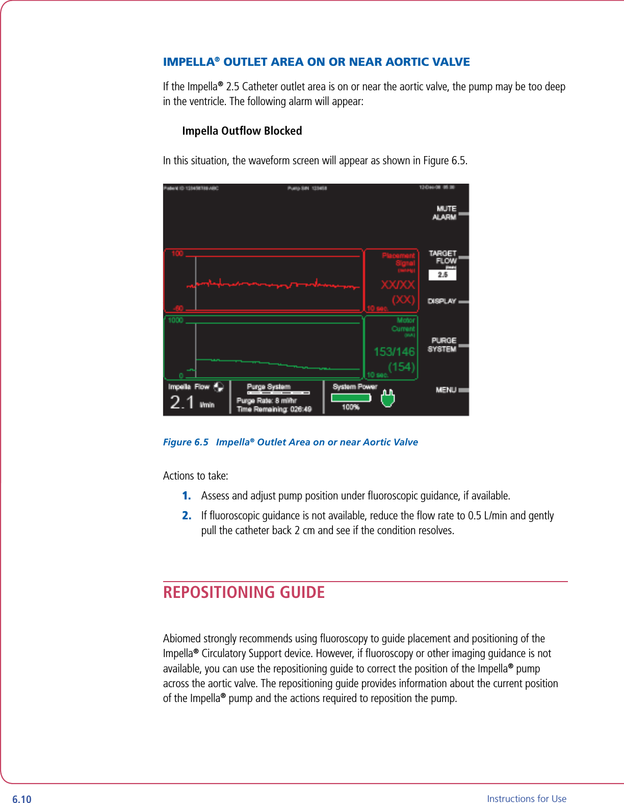
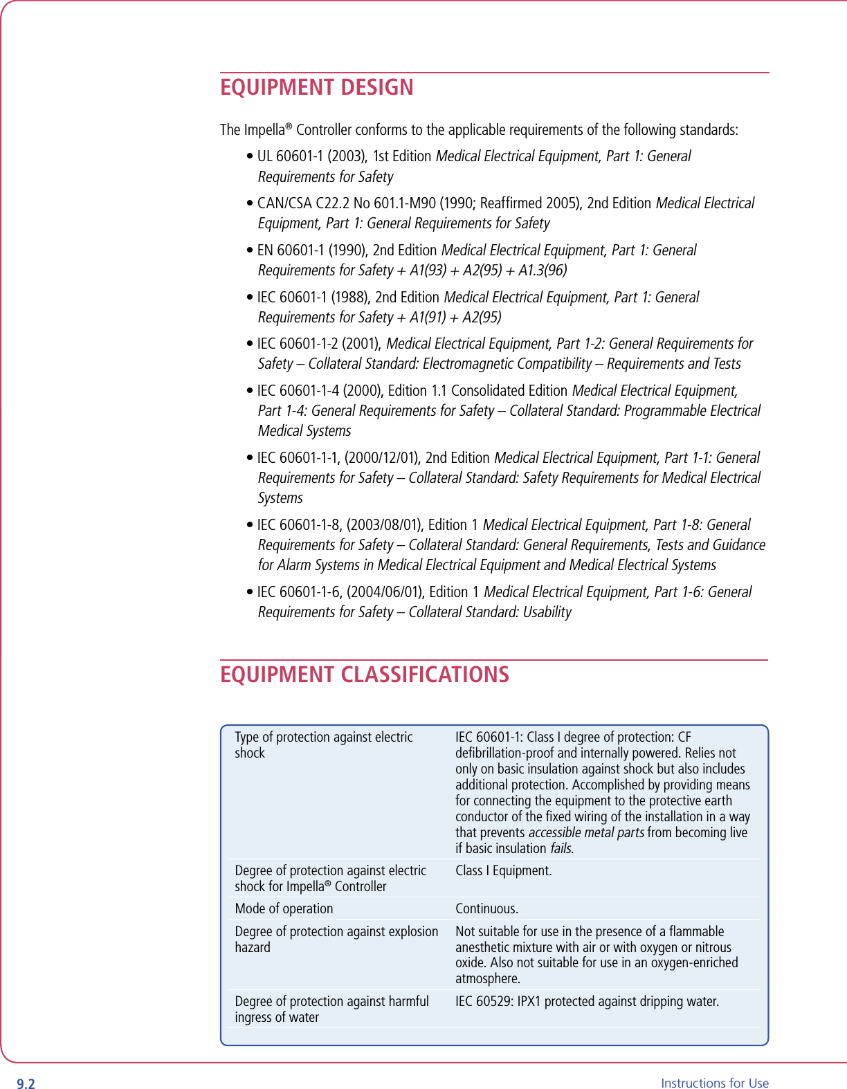
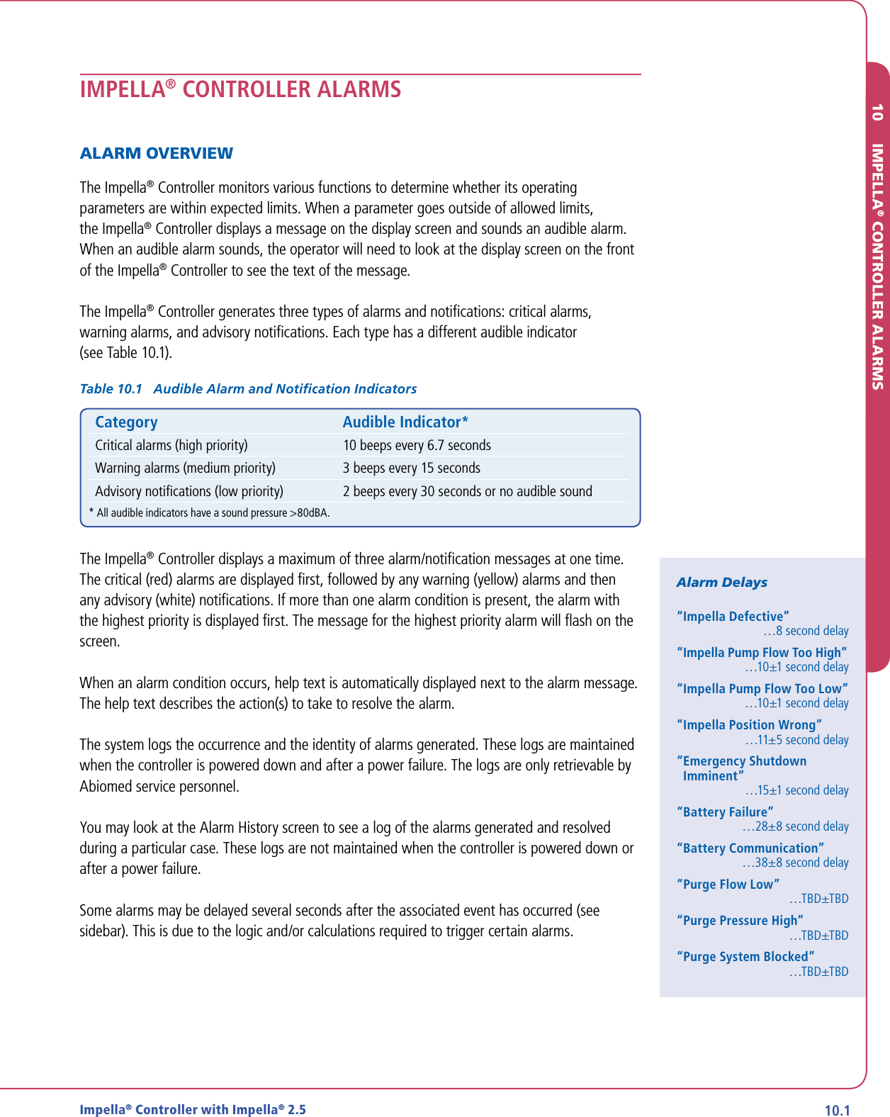
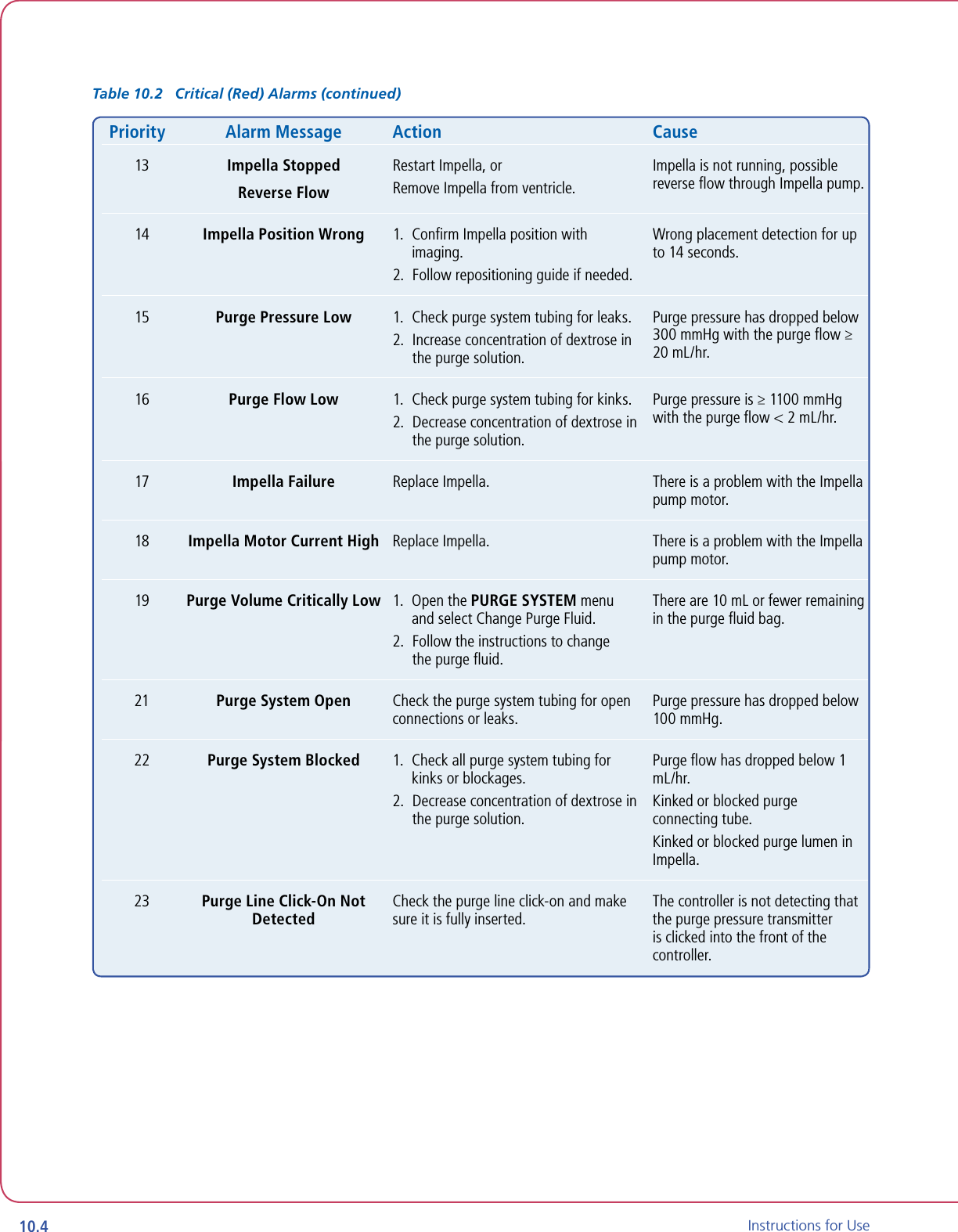
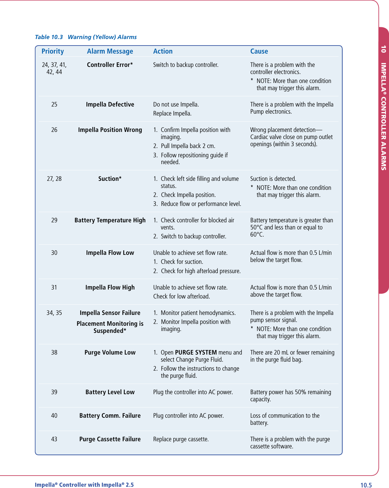
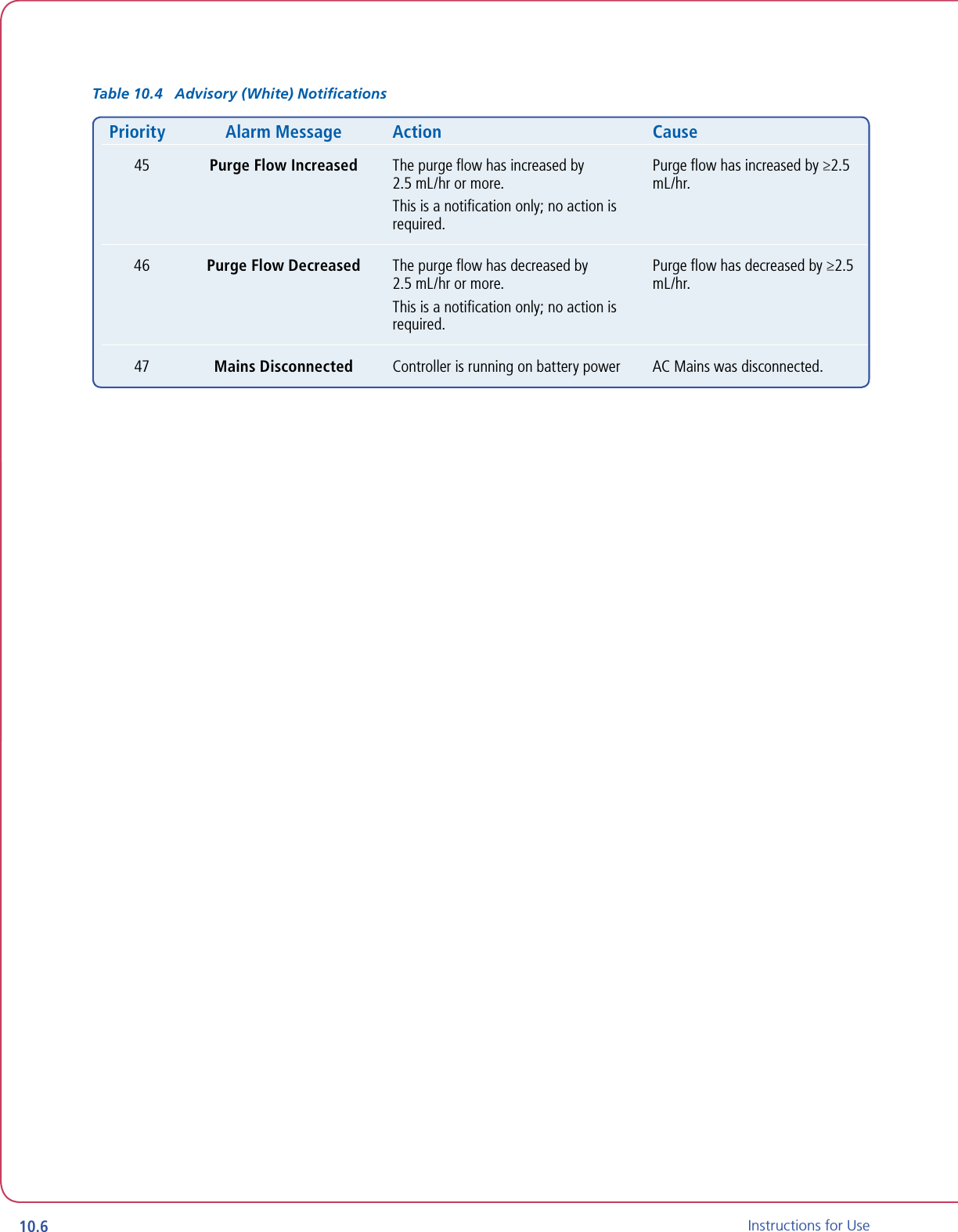
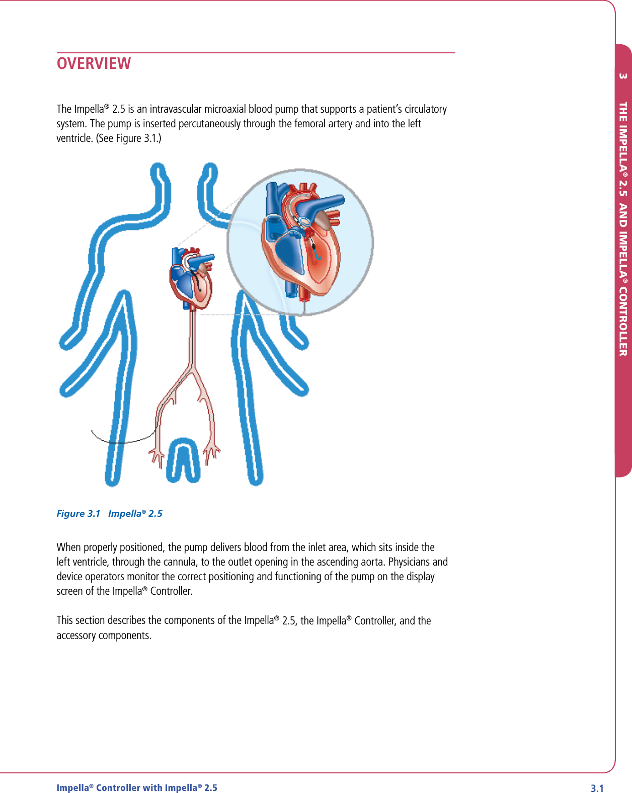
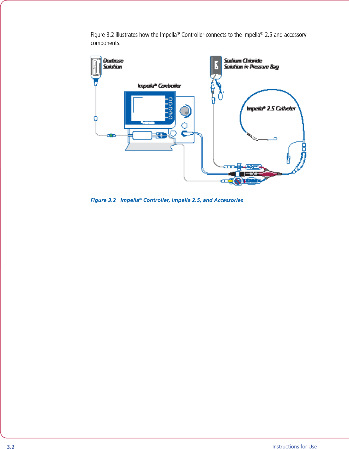
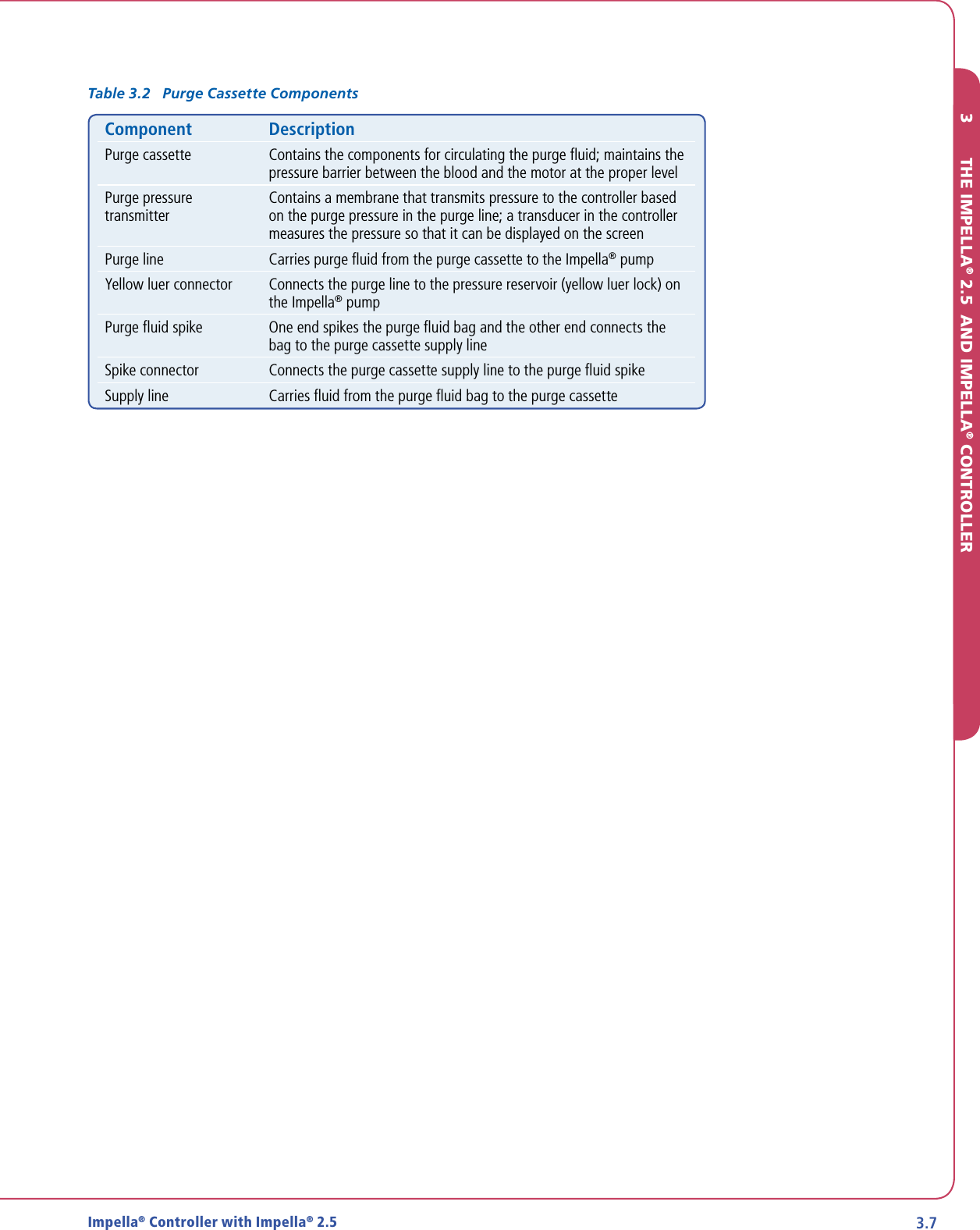
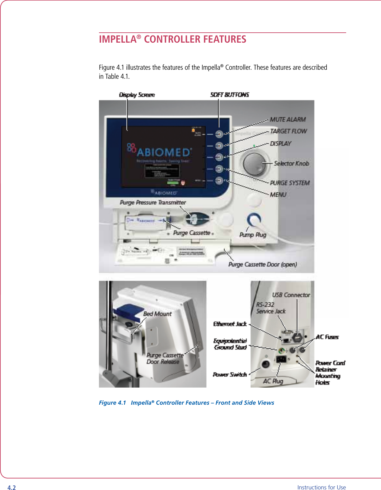
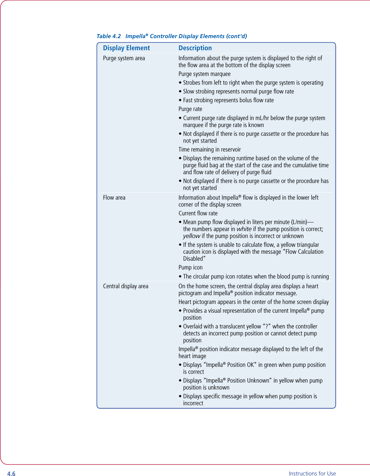
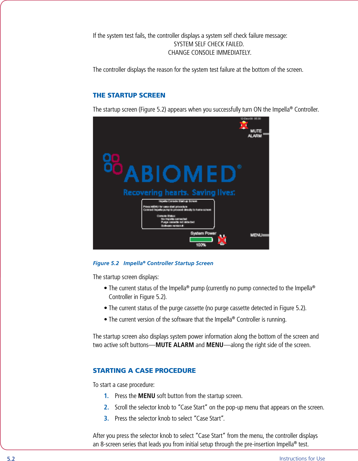
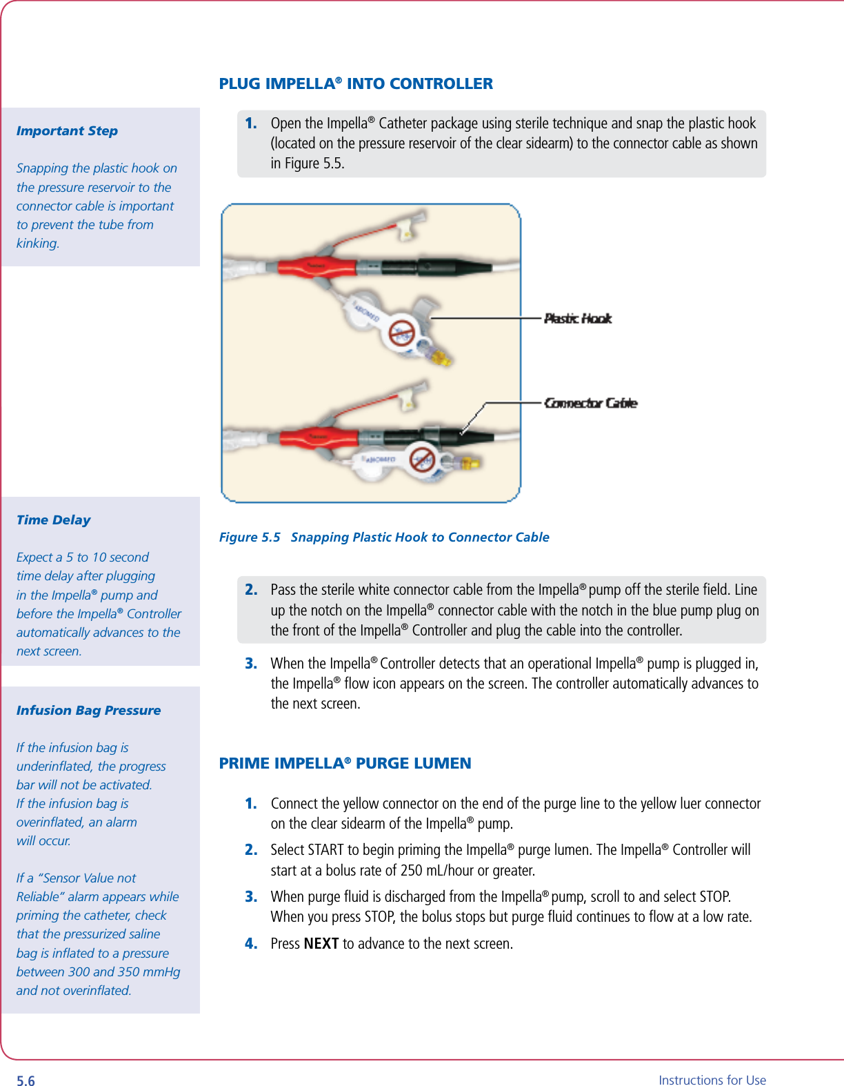
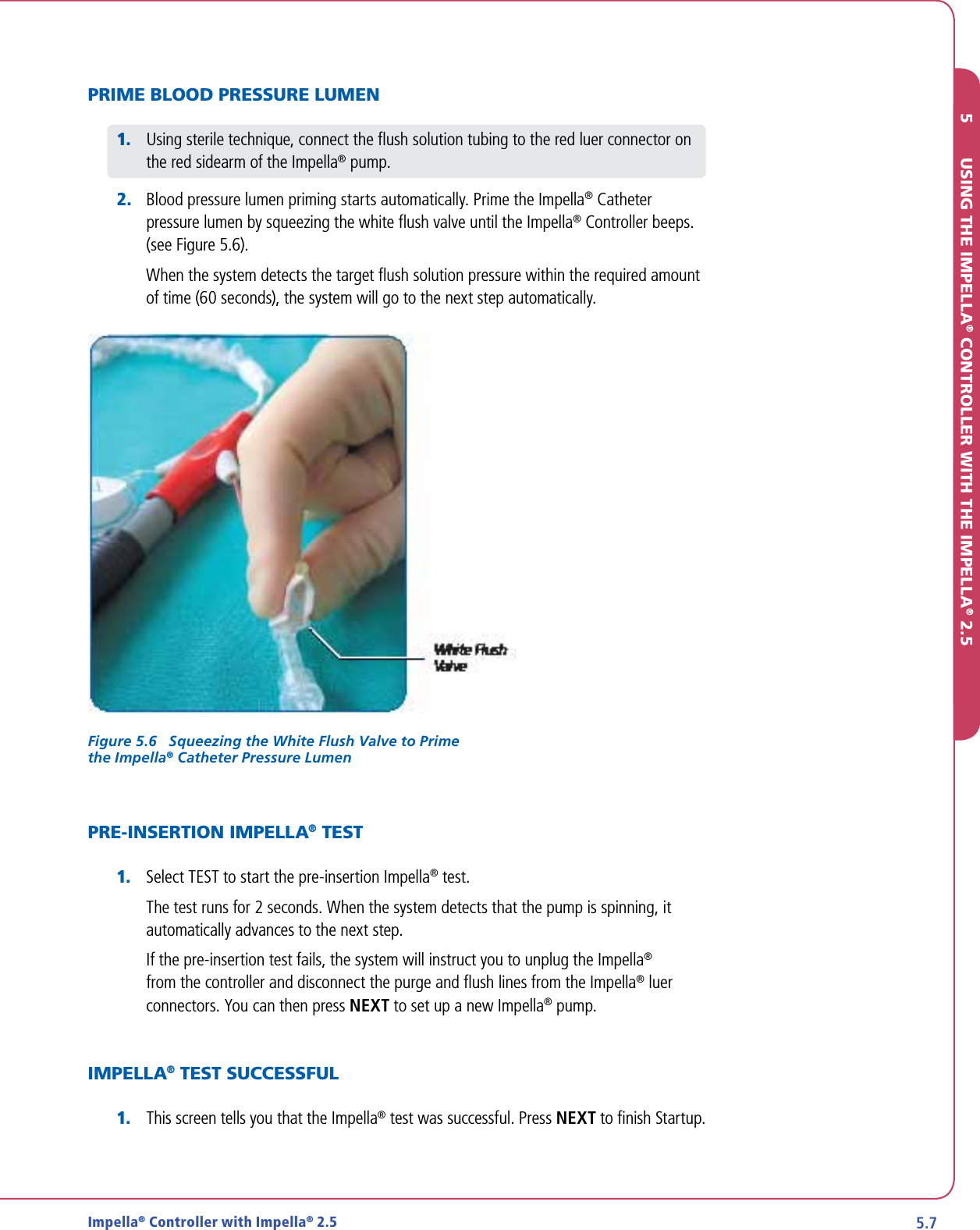
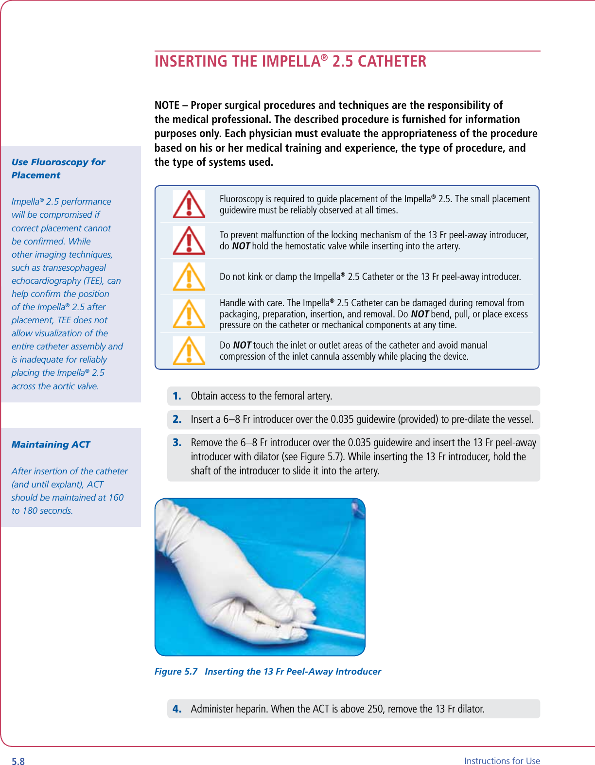
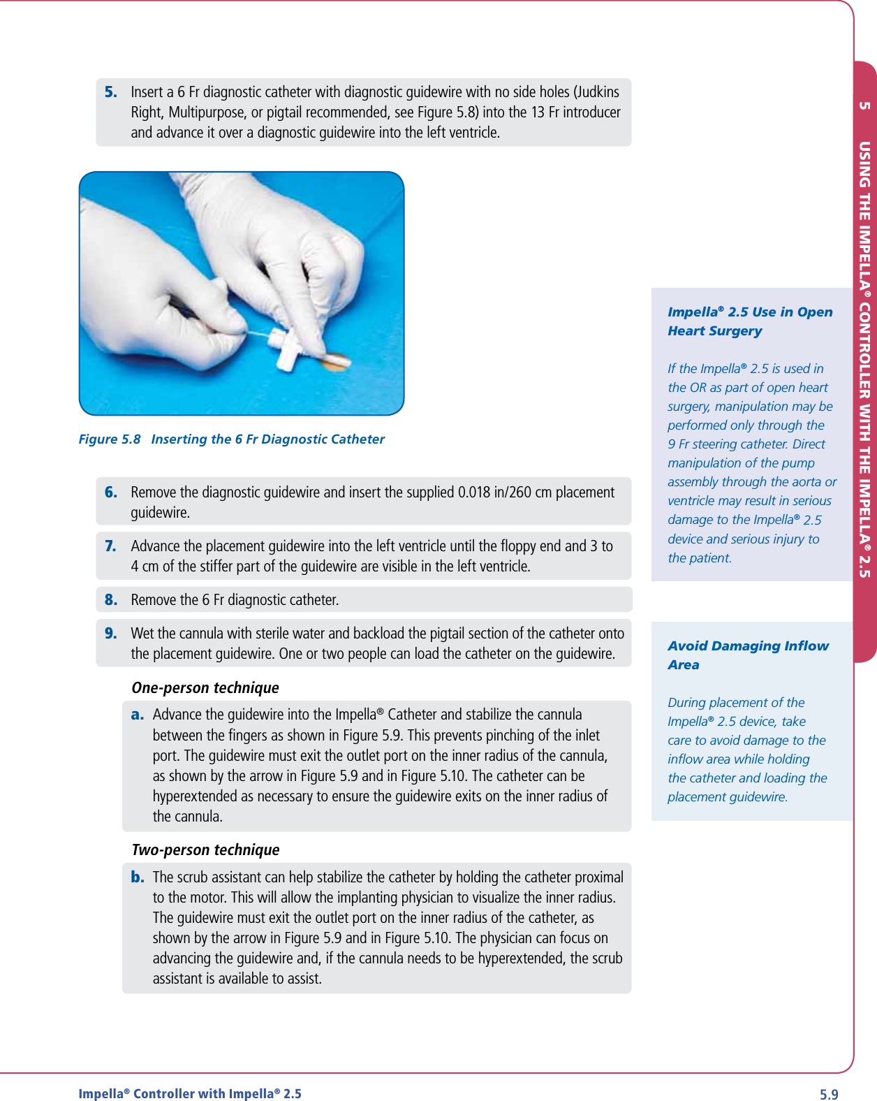
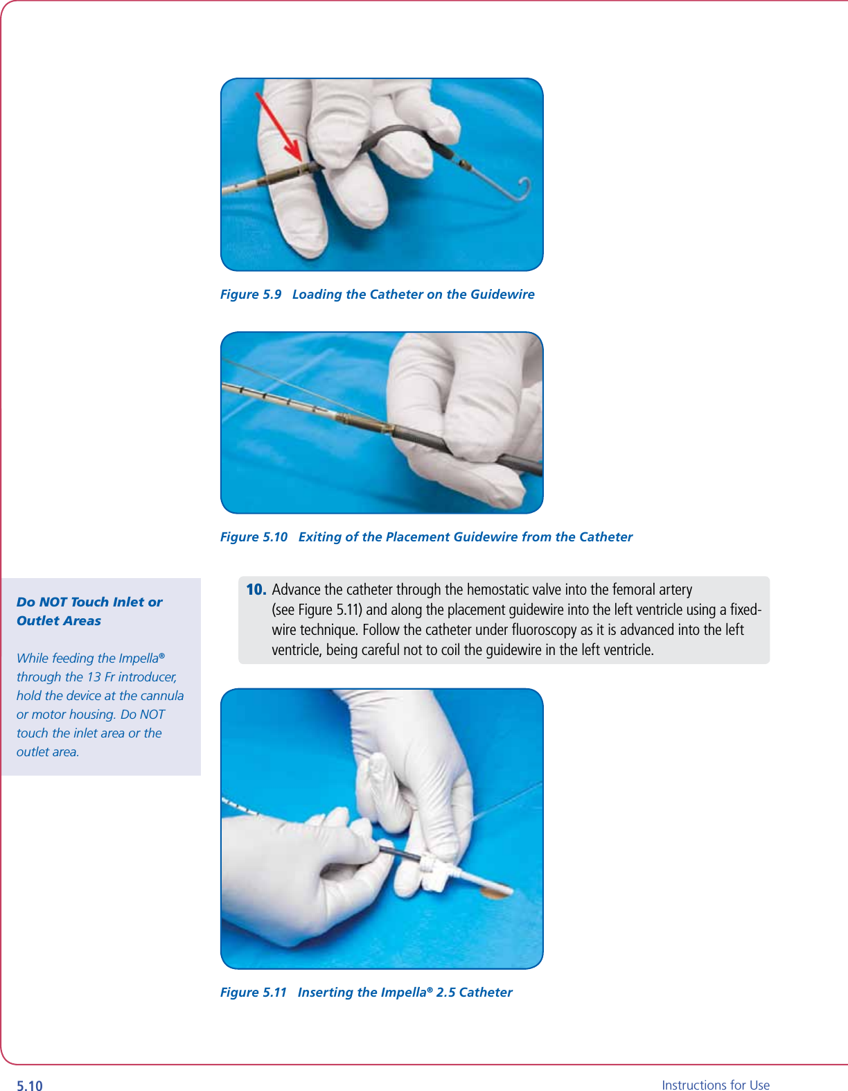
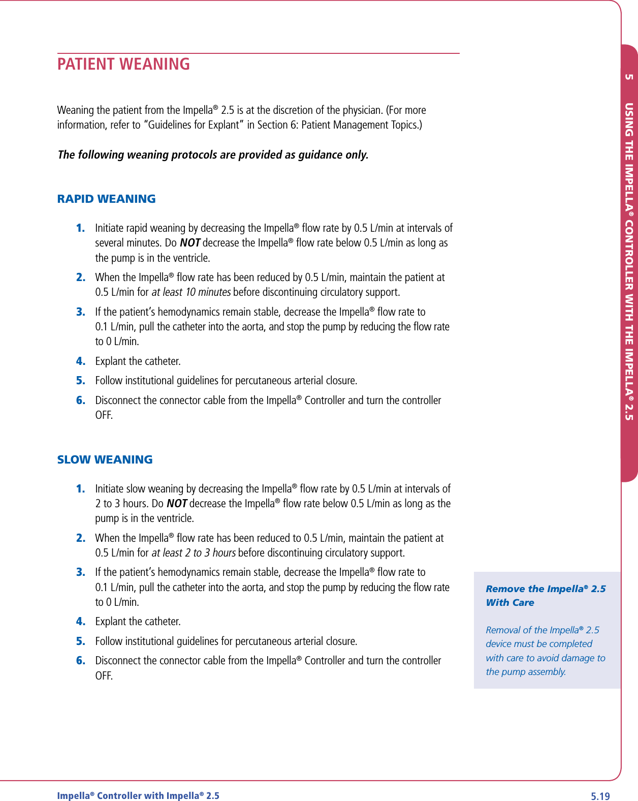
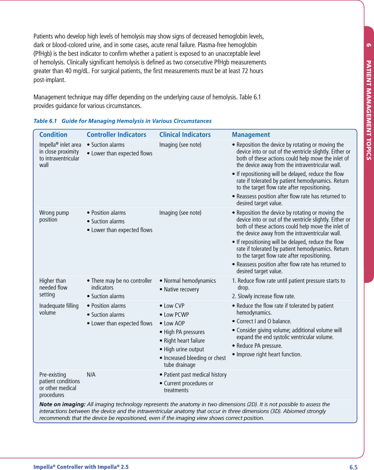
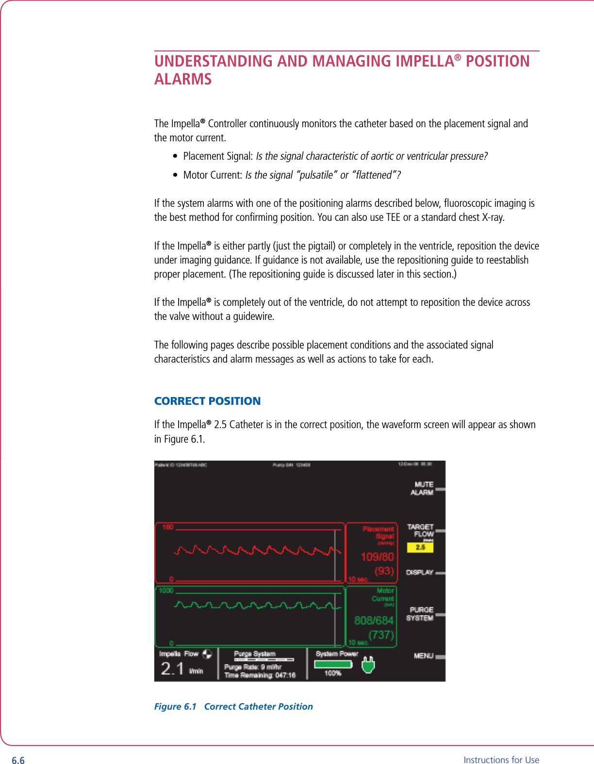
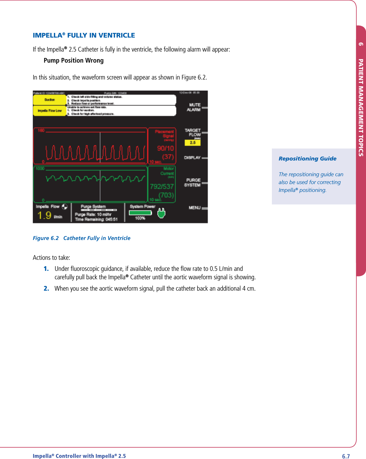
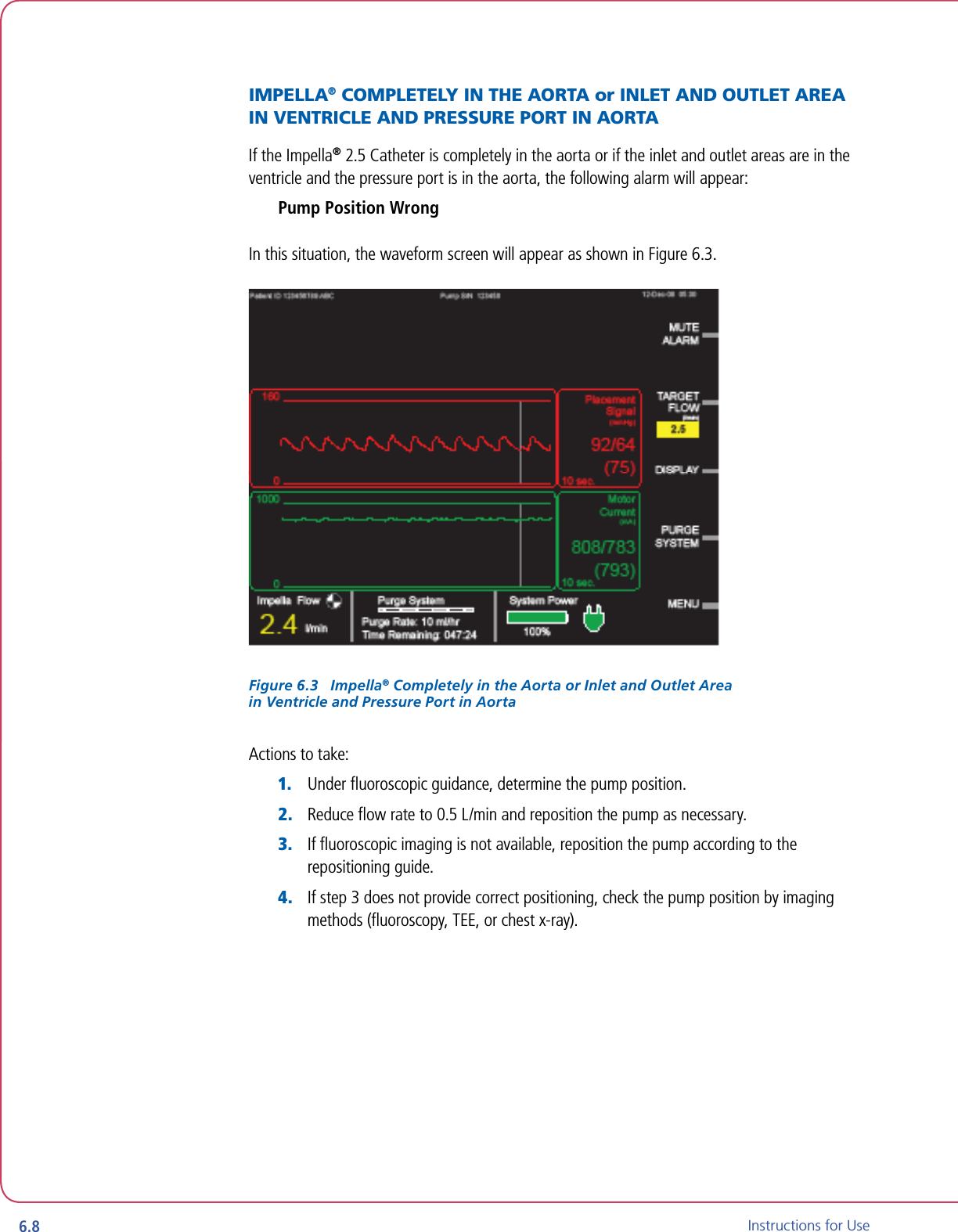
![TABLE OF CONTENTSFIGURESFigure 3.1 Impella® 2.5 ............................................................................... 3.1Figure 3.2 Impella® Controller, Impella 2.5, and Accessories ....................... 3.2Figure 3.3 Impella® 2.5 Catheter ................................................................ 3.3Figure 3.4 Impella® Controller – Front View ................................................ 3.5Figure 3.5 Purge Cassette ........................................................................... 3.6Figure 3.6 White Connector Cable .............................................................. 3.8Figure 3.7 Introducer Kit ............................................................................. 3.8Figure 3.8 0.018 in/260 cm Placement Guidewire ....................................... 3.8Figure 3.9 20% Dextrose in Water .............................................................. 3.9Figure 3.10 Impella® Controller Cart ........................................................... 3.9Figure 4.1 Impella® Controller Features – Front and Side Views .................. 4.2Figure 4.2 Impella® Controller Home Screen Display ................................... 4.4Figure 4.3 Waveform Screen Display (Waveform TBD) ................................. 4.7Figure 5.1 Impella® Controller Power Switch ............................................... 5.1Figure 5.2 Impella® Controller Startup Screen ............................................. 5.2Figure 5.3 Inserting Purge Cassette into Impella® Controller ....................... 5.4Figure 5.4 Default Values for Purge Fluid .................................................... 5.5Figure 5.5 Snapping Plastic Hook to Connector Cable ................................. 5.6Figure 5.6 Squeezing the White Flush Valve to Prime the Impella® Catheter Pressure Lumen ..................................... 5.7Figure 5.7 Inserting the 13 Fr Peel-Away Introducer .................................... 5.8Figure 5.8 Inserting the 6 Fr Diagnostic Catheter ........................................ 5.9Figure 5.9 Loading the Catheter on the Guidewire ...................................... 5.10Figure 5.10 Exiting of the Placement Guidewire from the Catheter .............. 5.10Figure 5.11 Inserting the Impella® 2.5 Catheter .......................................... 5.10Figure 5.12 Ventricular Waveform on Placement Signal Screen .................... 5.11Figure 5.13 Aortic Waveform on Placement Signal Screen ........................... 5.12Figure 5.14 Selecting Target Flow ............................................................... 5.12Figure 5.15 Confirming Placement on the Placement Signal Screen ............. 5.13Figure 5.16 Removing the 13 Fr Peel-Away Introducer ................................ 5.14Figure 6.1 Correct Catheter Position ........................................................... 6.6Figure 6.2 Catheter Fully in Ventricle .......................................................... 6.7Figure 6.3 Impella® Completely in the Aorta or Inlet and Outlet Areain Ventricle and Pressure Port in Aorta ..................................... 6.8Figure 6.4 Pump Position Unknown Due to Low Pulsatility [Waveform TBD; Motor Current y-axis scale to be revised] ....... 6.9Figure 6.5 Impella® Outlet Area on or near Aortic Valve ............................. 6.10Figure 6.6 First Repositioning Guide Screen ................................................ 6.11Figure 6.7 Second Repositioning Guide Screen ........................................... 6.11Figure 6.8 Third Repositioning Guide Screen ............................................... 6.12Figure 6.9 Exit Repositioning Guide Screen ................................................. 6.12Figure 6.10 Infusion History Screen ............................................................. 6.13Figure 9.1 Impella® Controller Patient Environment..................................... 9.7Figure 9.2 Impella® 2.5 Dimensions ............................................................ 9.9Figure B.1 Inspection Sticker Showing Inspection Required in May 2010 ..... B.1TABLESTable 3.1 Impella® 2.5 Catheter Components .......................................... 3.3Table 3.2 Purge Cassette Components .................................................... 3.7Table 3.3 Impella® 2.5 and Impella® Controller Accessories .................... 3.8Table 4.1 Impella® Controller Features .................................................... 4.3Table 4.2 Impella® Controller Display Elements ....................................... 4.4Table 6.1 Guide for Managing Hemolysis in Various Circumstances ......... 6.5Table 8.1 Terminology and Abbreviations ................................................ 8.1Table 8.2 Symbols ................................................................................... 8.1Table 10.1 Audible Alarm and Notification Indicators................................ 10.1Table 10.2 Critical (Red) Alarms ................................................................ 10.3Table 10.3 Warning (Yellow) Alarms.......................................................... 10.5Table 10.4 Advisory (White) Notifications ................................................. 10.6](https://usermanual.wiki/ABIOMED/0042-4000/User-Guide-1191677-Page-7.png)


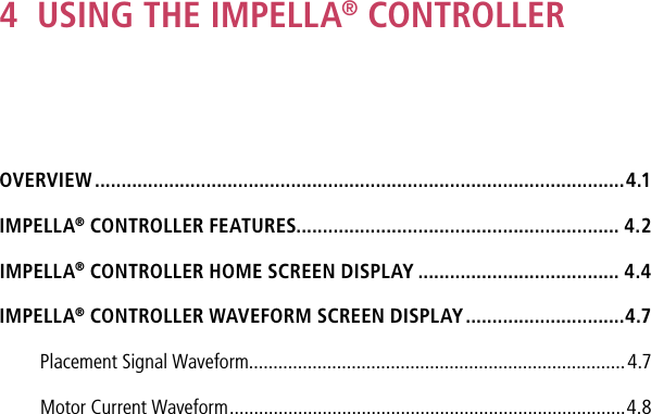


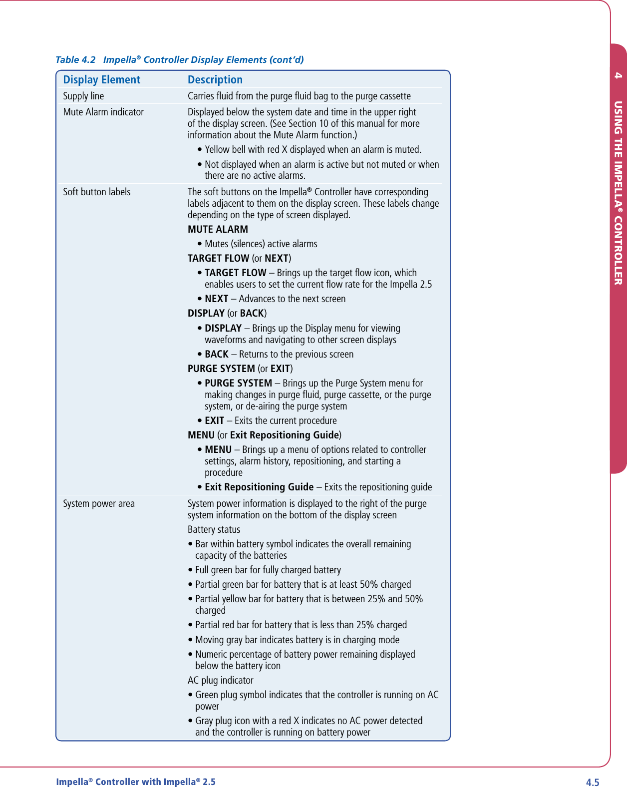


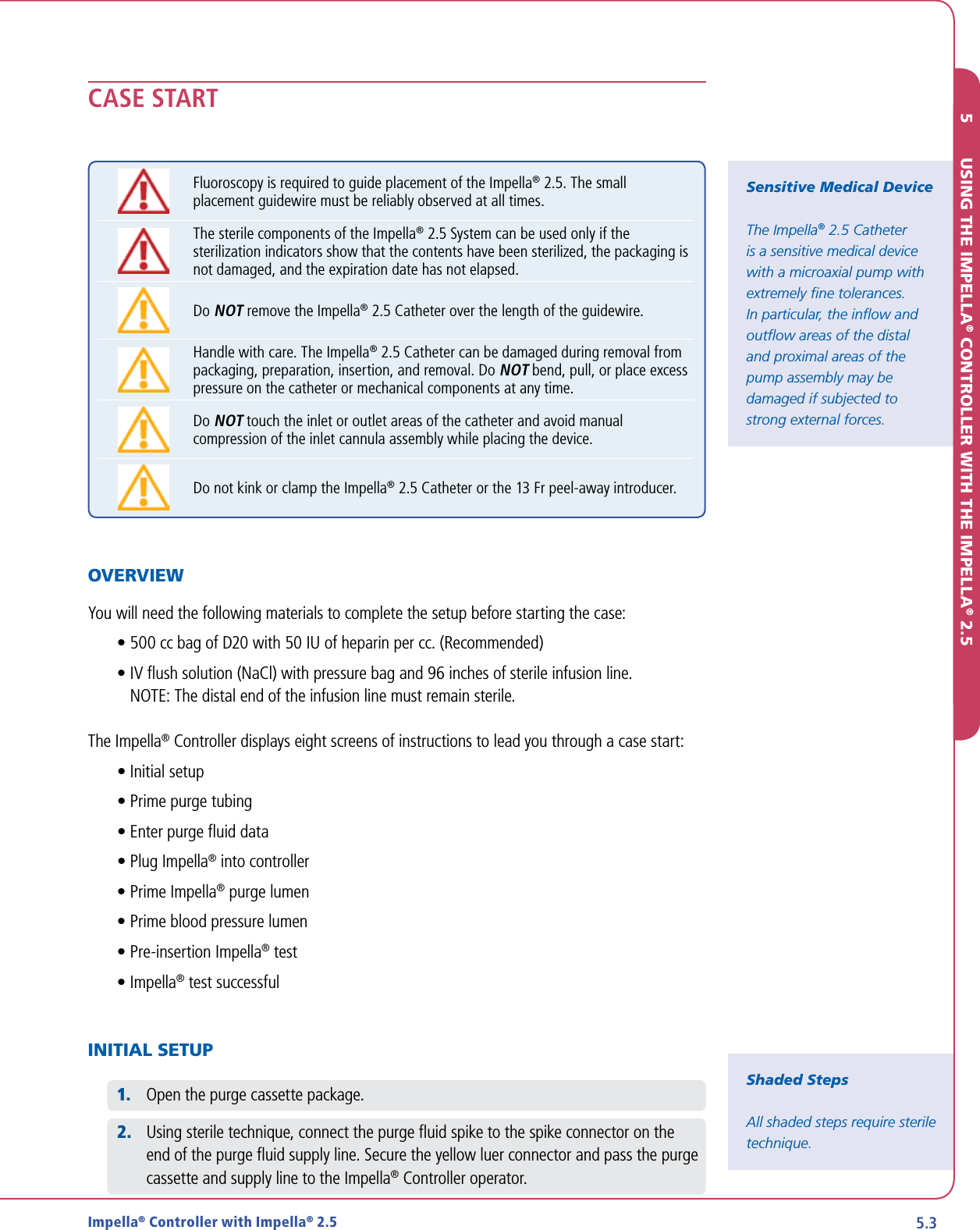

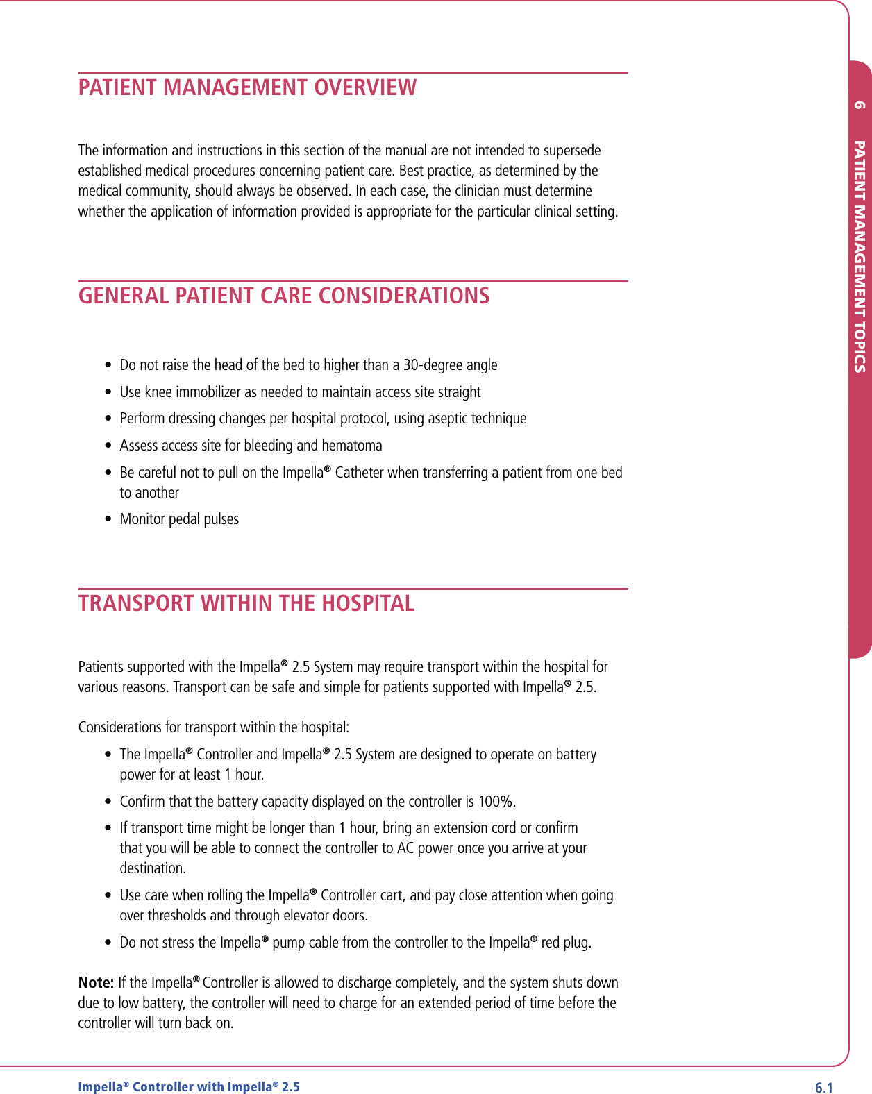
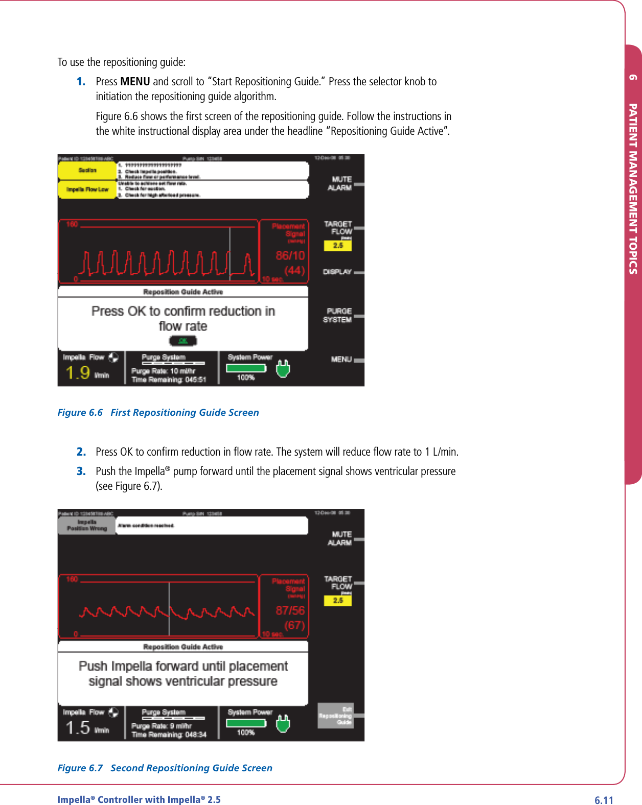
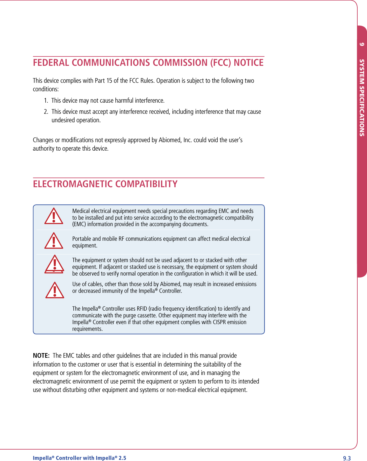
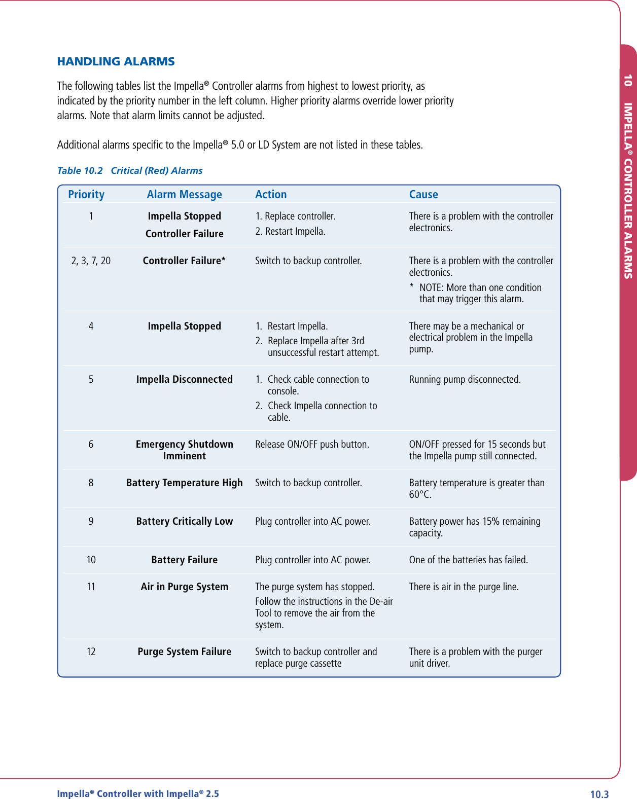
![6.9Impella® Controller with Impella® 2.5LOW NATIVE HEART PULSATILITYIn a situation of low native heart pulsatility, the Impella® Controller may not be able to determine the pump position. You may see the following alarm:Pump position unknown due to low pulsatility.In this situation, the waveform screen will appear as shown in Figure 6.4.Figure 6.4 Pump Position Unknown Due to Low Pulsatility[Waveform TBD; Motor Current y-axis scale to be revised]Actions to take:1. Assess cardiac function.6 PATIENT MANAGEMENT TOPICS](https://usermanual.wiki/ABIOMED/0042-4000/User-Guide-1191677-Page-77.png)