ACS Solutions Switzerland 800-0076 Ticket Vending Machine FVD Expert 9100 US User Manual SP 10 000 006 785 E00 04 000x
ACS Solutions Switzerland Ltd. Ticket Vending Machine FVD Expert 9100 US SP 10 000 006 785 E00 04 000x
Contents
- 1. UserManual.pdf
- 2. UserManualSafetyInstructions.pdf
UserManual.pdf
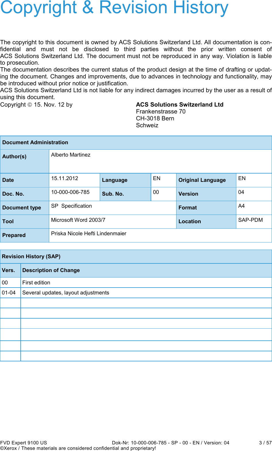
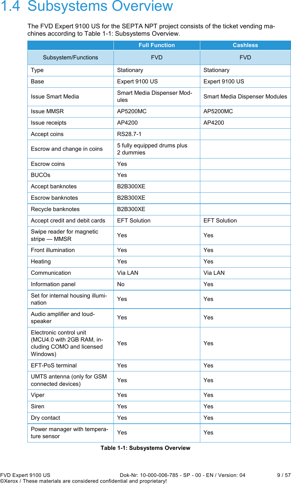
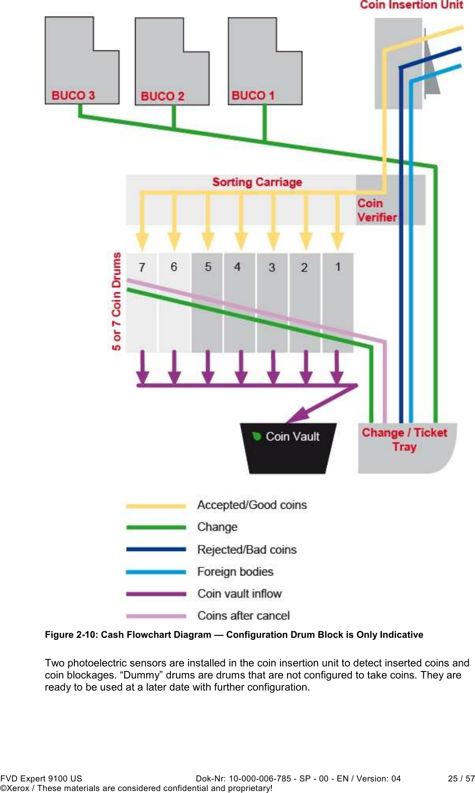
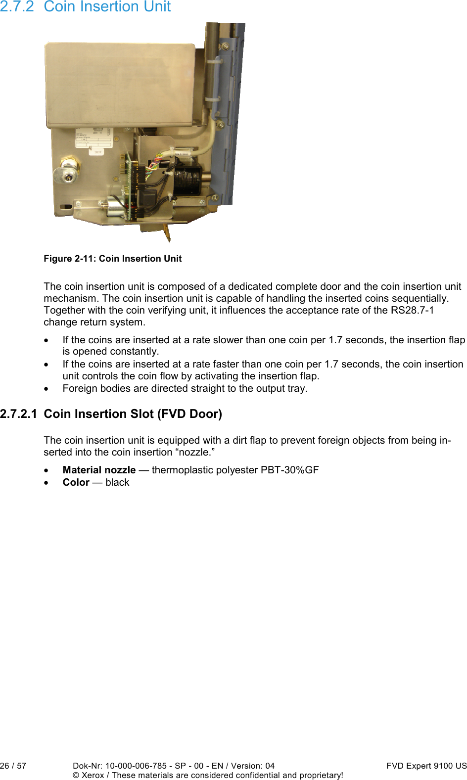
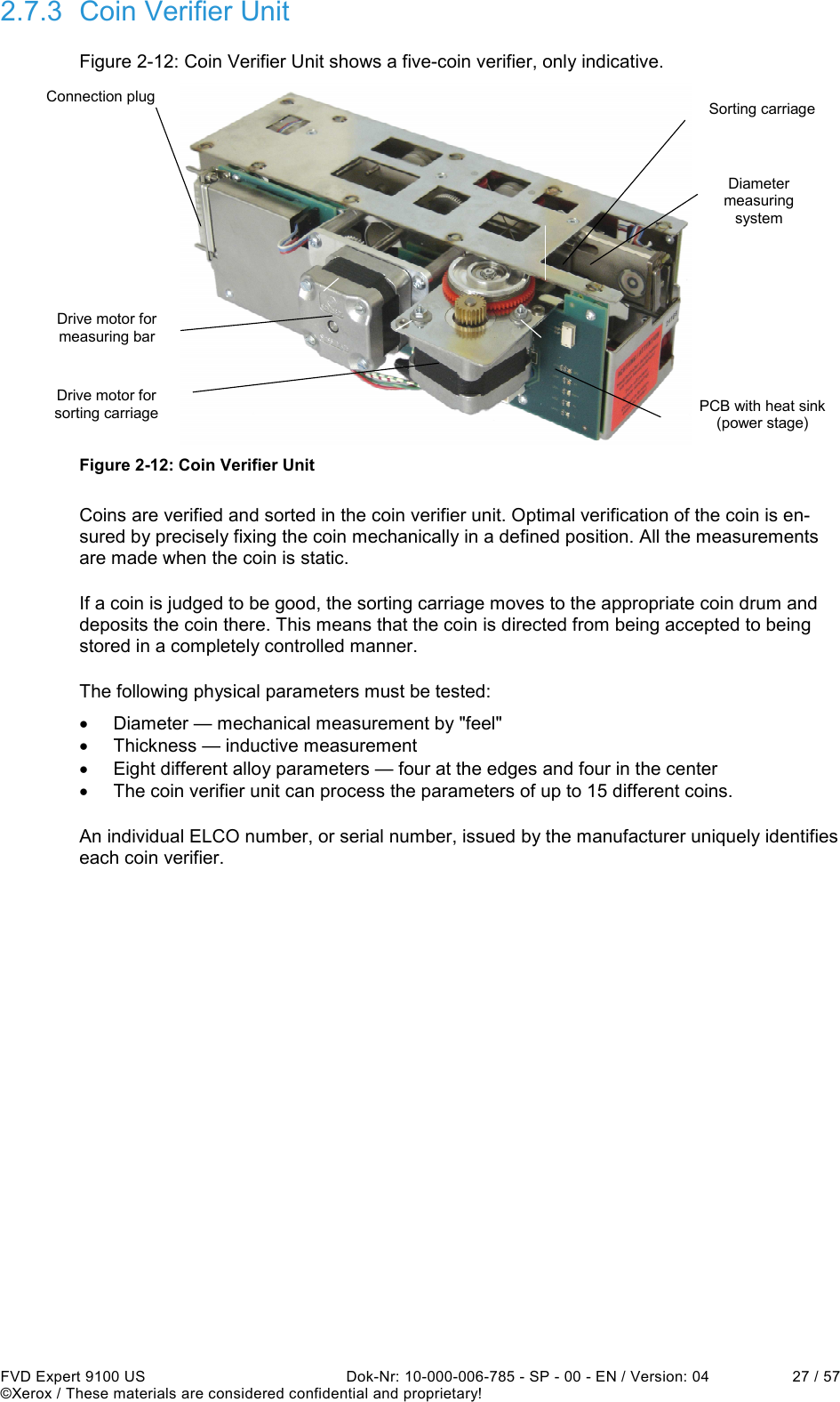
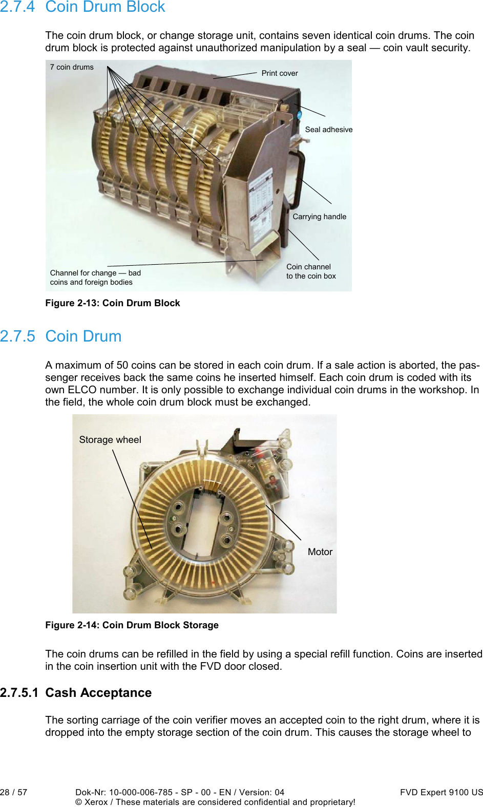
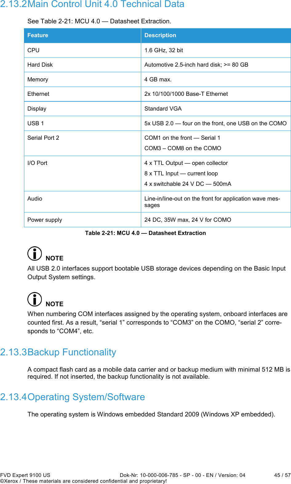
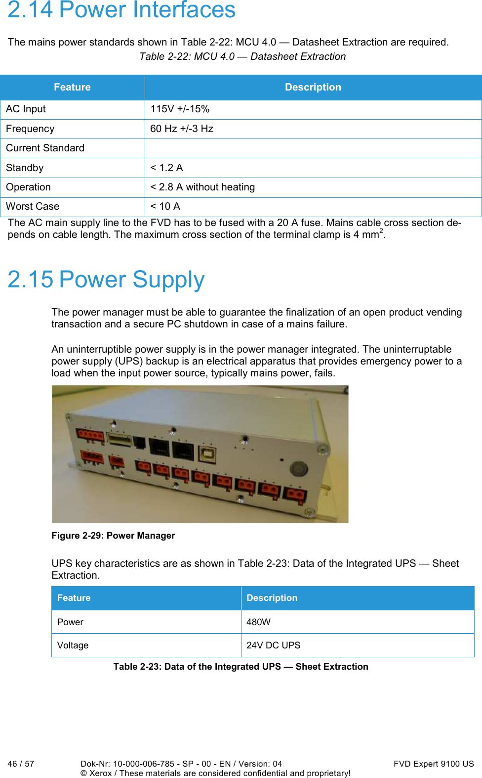
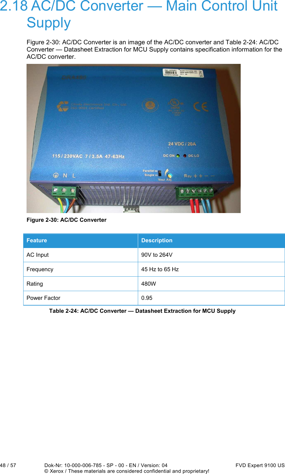
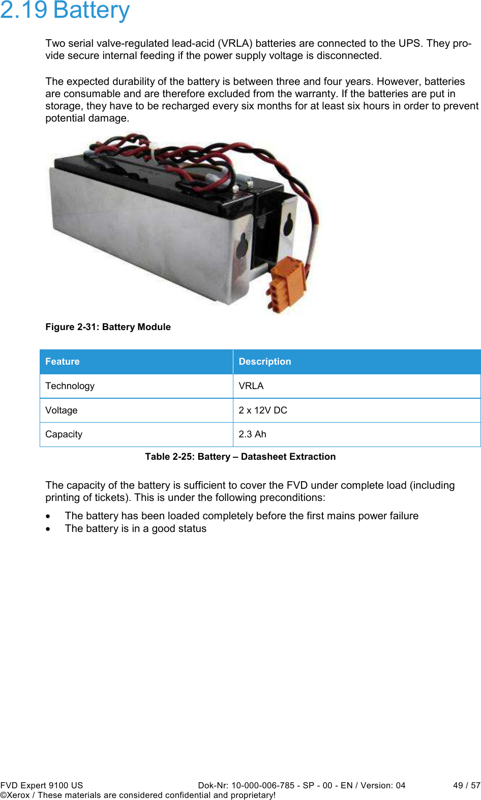
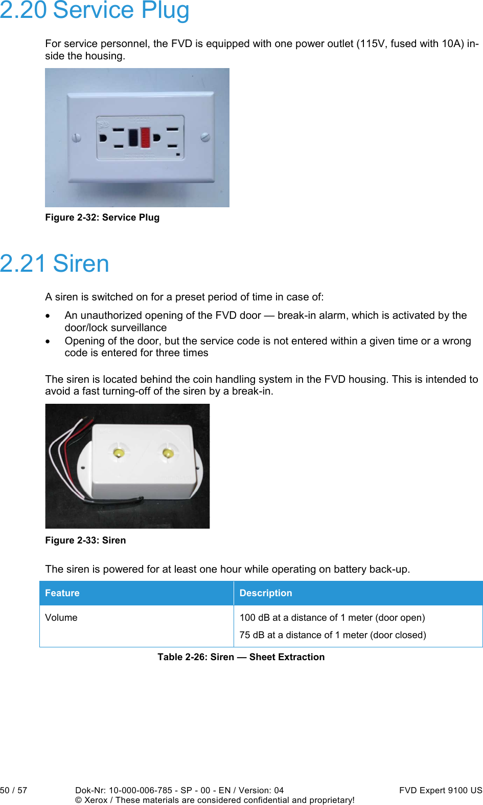
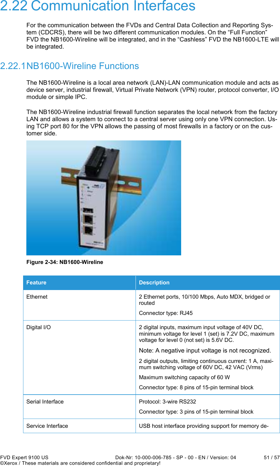
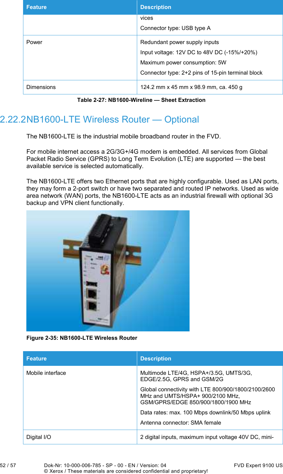
![8 / 57 Dok-Nr: 10-000-006-785 - SP - 00 - EN / Version: 04 FVD Expert 9100 US ©Xerox / These materials are considered confidential and proprietary! 1 About this document 1.1 Introduction This document specifies the configuration and technical description of the Expert 9100 US Fare Vending Device (FVD) for the SEPTA New Payment Technologies (NPT) system. NOTE: Features not listed in the table or explicitly defined in the Technical Specification are exclud-ed. 1.2 Audience The intended audience of this document includes the SEPTA NPT project members. 1.3 Related Documents This Fare Vending Device Hardware Specification document is part of a larger series, which includes: Manuals [1] Fare Vending Device Overview – 10-000-00x-xxx E00 BH [2] Fare Vending Device Functional Specification – 10-000-00x-xxx E00 BH [3] Fare Vending Device Compliance Matrix – 10-000-00x-xxx E00 BH](https://usermanual.wiki/ACS-Solutions-Switzerland/800-0076.UserManual-pdf/User-Guide-1941566-Page-8.png)