AMX MVP9 WiFi Touch Panel User Manual 93 5967 01 MVP 9000i InstallationGuide revA
AMX LLC WiFi Touch Panel 93 5967 01 MVP 9000i InstallationGuide revA
UserManual.wiki
>
AMX
>
MVP9 User Manual
>
Install Guide
Contents
1.
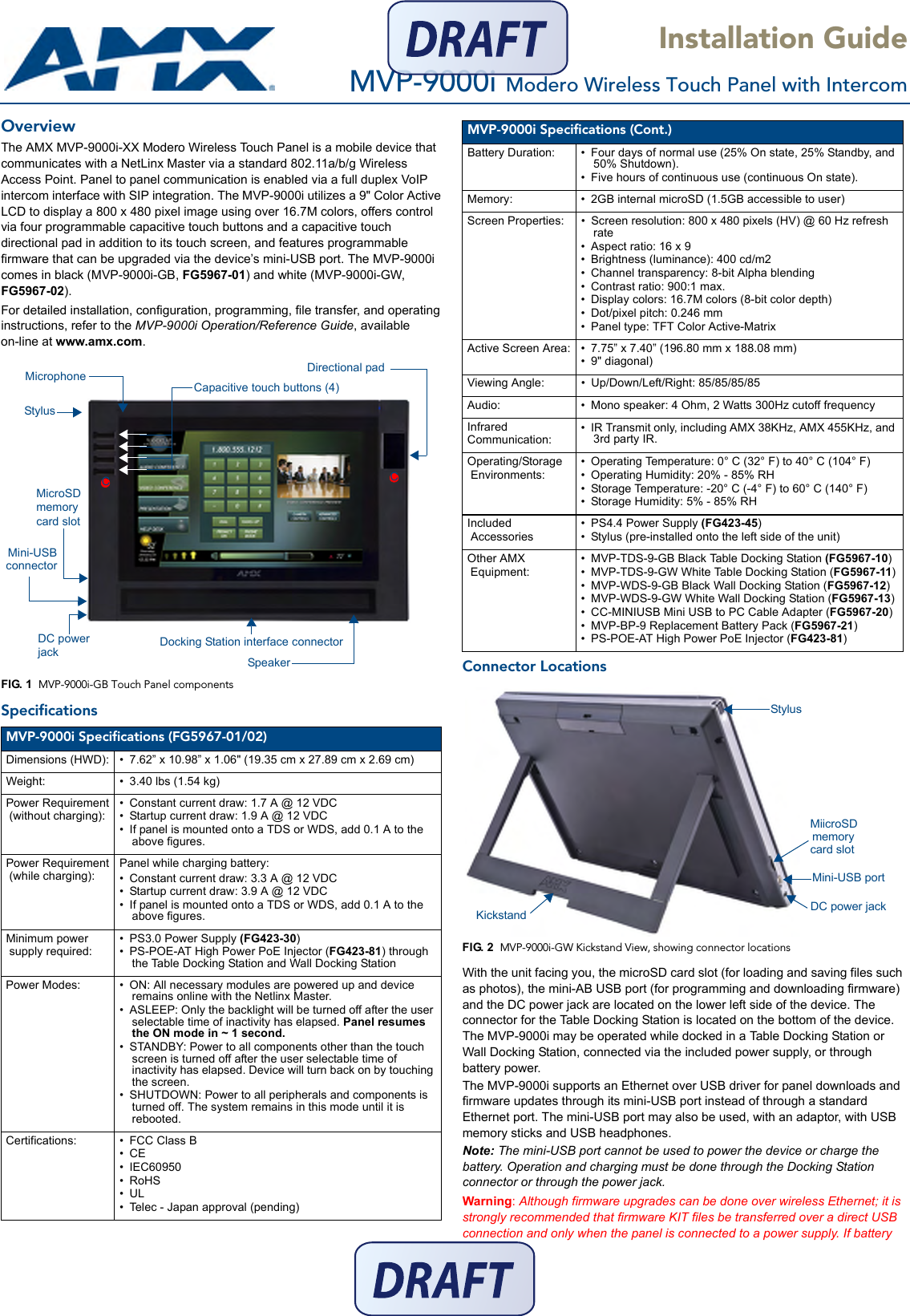
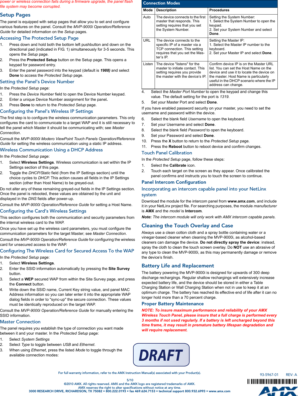
Install Guide
2.
Final User's Manual
Install Guide
Navigation menu
Upload a User Manual
Namespaces
Wiki Guide
HTML
PDF
Info
Views
User Manual
Discussion / Help
Navigation