Belkin F5D8636V2 N Wireless Modem Router User Manual Manual Part 1
Belkin International, Inc. N Wireless Modem Router Manual Part 1
Belkin >
Contents
- 1. Manual Part 1
- 2. Manual Part 2
Manual Part 1
N Wireless
Modem Router
User Manual
PM01527ea-C F5D8636-4 English
Français
DEutsch
nEDErlanDs
Español
italiano
v2

i
N Wireless Modem Router
SECTIONS 12345678910
Table of Contents
TABLE OF CONTENTS
6 Using the Web-Based Advanced User Interface ........... 38
Changing LAN Settings.....................................39
Viewing the DHCP Client List Page ...........................41
Configuring the Wireless Network Settings .....................41
Setting WPA Security ......................................49
Setting WEP Encryption ....................................50
Setting MAC Address Control ...............................52
Configuring the Firewall ....................................54
Using Dynamic DNS .......................................59
Utilities ..................................................61
Restarting the Router ......................................61
Updating the Firmware .....................................66
7 Manually Configuring Network Settings .................. 74
8 Recommended Web Browser Settings ................... 79
9 Troubleshooting ....................................... 81
10 Information .......................................... 94
1 Introduction . . . . . . . . . . . . . . . . . . . . . . . . . . . . . . . . . . . . . . . . . . . . 1
Advantages of a Wireless Network ............................1
Placement of your N Wireless Modem Router....................3
2 Product Overview. . . . . . . . . . . . . . . . . . . . . . . . . . . . . . . . . . . . . . . . 6
Product Features. . . . . . . . . . . . . . . . . . . . . . . . . . . . . . . . . . . . . . . . . . . 6
3 Knowing your Modem Router . . . . . . . . . . . . . . . . . . . . . . . . . . . . . 8
Package Contents ..........................................8
System Requirements .......................................9
Setup Assistant Software System Requirements .................9
4 Connecting and Configuring your Modem Router .......... 13
5 Alternate Setup Method ............................... 27

1
N Wireless Modem Router
SECTIONSTable of Contents 2345678910
1
INTRODUCTION
Thank you for purchasing the Belkin N Wireless Modem Router (the Router). Following are two short sections—the first discusses
the benefits of home networking, and the other outlines best practices that maximize your wireless home network range and
performance. Please be sure to read through this User Manual completely, and pay special attention to the section entitled
“Placement of your N Wireless Modem Router” on page 3.
Advantages of a Wireless Network
Here are some of the advantages of setting up a Belkin Wireless Network:
• Mobility – you’ll no longer need a dedicated “computer room”—
now you can work on a networked laptop or desktop computer
anywhere within your wireless range
• Easy installation – Belkin’s Setup Assistant application makes
setup simple
• Flexibility – set up and access printers, computers, and other
networking devices from anywhere in your home
• Easy Expansion – the wide range of Belkin networking products let
you expand your network to include devices such as printers and
gaming consoles
• No cabling required – you can spare the expense and hassle of
retrofitting Ethernet cabling throughout the home or office
• Widespread industry acceptance – choose from a wide range of
interoperable networking products.
• Share one high-speed Internet connection with all the computers in
your home
• Share resources, such as files and hard drives among all the
connected computers in your home
• Share a single printer with the entire family
• Share documents, music, video, and digital pictures
• Store, retrieve, and copy files from one computer to another
• Simultaneously play games online, check Internet email, and chat
Benefits of a Home Network

2
N Wireless Modem Router
SECTIONSTable of Contents 2345678910
1
INTRODUCTION
Revolutionary N Wireless Technology with MIMO (N MIMO)
Think of conventional radio transmission as a two-lane highway. The
speed limit governs the maximum allowable flow of traffic through
that lane. Compared with conventional radios, one-dimensional smart
antenna systems help move traffic through that lane faster and more
reliably—analogous to a four-lane road on which traffic consistently
moves at a rate closer to the speed limit. Belkin’s N MIMO helps
traffic move at the speed limit and opens more lanes—to become the
superhighway in this example. The rate of traffic flow is multiplied by the
number of lanes that are opened.
Your Belkin N Wireless Modem Router uses a new smart-antenna
technology called Multiple Input Multiple Output (MIMO). N MIMO
complies with the IEEE draft 802.11n specification. It increases
speed, range, reliability, and spectral efficiency for wireless
networking systems.
The element that makes Belkin’s N MIMO technology different
from a conventional radio is the use of multiple antennas and two
simultaneous data streams to deliver wireless transfers around your
home or office. A conventional radio uses one antenna to transmit a
data stream. Belkin’s N MIMO, on the other hand, uses two antennas.
This design helps combat distortion and interference. Belkin’s N MIMO
is multidimensional. It builds on one-dimensional smart-antenna
technology by simultaneously transmitting two data streams through the
same channel, which increases wireless capacity.
Another element that enhances Belkin’s N MIMO is the use of
aggregation as specified in the draft 802.11n specification. By shortening
the space between packets and combining multiple smaller packets
into one larger packet, Belkin’s N MIMO can transmit more data through
available bandwidth.

3
N Wireless Modem Router
SECTIONSTable of Contents 2345678910
1
INTRODUCTION
• Ensure that your Router’s networking antennas are parallel to each
other, and are positioned vertically (toward the ceiling). If your
Router itself is positioned vertically, point the antennas as much as
possible in an upward direction.
• In multistory homes, place the Router on a floor that is as close
to the center of the home as possible. This may mean placing the
Router on an upper floor.
• Try not to place the Router near a cordless 2.4GHz phone.
2. Avoid Obstacles and Interference
Avoid placing your Router near devices that may emit radio “noise,”
such as microwave ovens. Dense objects that can inhibit wireless
communication include:
• Refrigerators
• Washers and/or dryers
• Metal cabinets
• Large aquariums
• Metallic-based UV tinted windows
Placement of your N Wireless Modem Router
Important Factors for Placement and Setup
Your wireless connection will be stronger the closer your computer is
to your Router. Typical indoor operating range for wireless devices is
between 100 and 200 feet.
In the same way, your wireless connection and performance will degrade
somewhat as the distance between your Router and connected devices
increases. This may or may not be noticeable to you. As you move
further from your Router, connection speed may decrease. Factors that
can weaken signals simply by getting in the way of your network’s radio
waves are metal appliances or obstructions, and walls.
If you have concerns about your network’s performance that might
be related to range or obstruction factors, try moving the computer to
a position between five and 10 feet from the Router in order to see if
distance is the problem. If difficulties persist even at close range, please
contact Belkin Technical Support.
Note: While some of the items listed below can affect network
performance, they will not prohibit your wireless network from
functioning; if you are concerned that your network is not operating at
its maximum effectiveness, this checklist may help.
1. Router Placement
Place your Router, the central connection point of your network, as
close as possible to the center of your wireless network devices.
To achieve the best wireless network coverage for your “wireless clients”
(i.e., computers enabled by Belkin Wireless Notebook Network Cards,
Wireless Desktop Network Cards, and Wireless USB Adapters):

4
N Wireless Modem Router
SECTIONSTable of Contents 2345678910
1
INTRODUCTION
4. Choose the “Quietest” Channel for your Wireless Network
In locations where homes or offices are close together, such as
apartment buildings or office complexes, there may be wireless
networks nearby that can conflict with yours.
Use the Site Survey capabilities found in the Wireless Utility of your
wireless adapter to locate any other wireless networks that are available
(see your wireless adapter’s user manual), and move your Router and
computers to a channel as far away from other networks as possible.
• Experiment with more than one of the available channels, in
order to find the clearest connection and avoid interference from
neighboring cordless phones or other wireless devices.
• For Belkin wireless networking products, use the detailed Site
Survey and wireless channel information included with your
wireless network card. See your network card’s user guide for
more information.
These guidelines should allow you to cover the maximum possible area
with your Router. Should you need to cover an even wider area, we
suggest the Belkin Wireless Universal Range Extender/Access Point.
If your wireless signal seems weak in some spots, make sure that
objects such as these are not blocking the signal’s path (between your
computers and Router).
3. Cordless Phones
If the performance of your wireless network is impaired after attending
to the above issues, and you have a cordless phone:
• Try moving cordless phones away from your Router and your
wireless-enabled computers.
• Unplug and remove the battery from any cordless phone that
operates on the 2.4GHz band (check manufacturer’s information). If
this fixes the problem, your phone may be interfering.
• If your phone supports channel selection, change the channel on
the phone to the farthest channel from your wireless network. For
example, change the phone to channel 1 and move your Router to
channel 11. See your phone’s user manual for detailed instructions.
• If necessary, consider switching to a 900MHz or 5GHz
cordless phone.

5
N Wireless Modem Router
SECTIONSTable of Contents 2345678910
1
INTRODUCTION
5. Secure Connections, VPNs, and AOL
Secure connections typically require a user name and password, and
are used where security is important. Secure connections include:
• Virtual Private Network (VPN) connections, often used to connect
remotely to an office network
• The “Bring Your Own Access” program from America Online (AOL),
which lets you use AOL through broadband provided by another
cable or DSL service
• Most online banking websites
• Many commercial websites that require a user name and password
to access your account
Secure connections can be interrupted by a computer’s power
management setting, which causes it to “go to sleep.” The simplest
solution to avoid this is to simply reconnect by rerunning the VPN or
AOL software, or by re-logging into the secure website.
A second alternative is to change your computer’s power management
settings so it does not go to sleep; however, this may not be appropriate
for portable computers. To change your power management setting
under Windows, see the “Power Options” item in the Control Panel.
If you continue to have difficulty with Secure Connections, VPNs, and
AOL, please review the steps above to be sure you have addressed
these issues.

6
N Wireless Modem Router
SECTIONSTable of Contents 1 345678910
PRODUCT OVERVIEW
2
Product Features
In minutes you will be able to share your Internet connection and
network your computers. The following is a list of features that make
your new Belkin N Wireless Modem Router an ideal solution for your
home or small office network.
Works with Both PCs and Mac® Computers
The Router supports a variety of networking environments including
Mac OS® 8.x, 9.x, X v10.x, Linux®, Windows® 98, Me, NT®, 2000, XP, and
Vista®. All that is needed is an Internet browser and a network adapter
that supports TCP/IP (the standard language of the Internet).
Network Status Display
Lighted LEDs on the front of the Router indicate which functions are in
operation. You’ll know at-a-glance whether your Router is connected to
the Internet. This feature eliminates the need for advanced software and
status-monitoring procedures.
Web-Based Advanced User Interface
You can set up the Router’s advanced functions easily through your web
browser, without having to install additional software onto the computer.
There are no disks to install or keep track of and, best of all, you can
make changes and perform setup functions from any computer on the
network quickly and easily.
NAT IP Address Sharing
Your Router employs Network Address Translation (NAT) to share the
single IP address assigned to you by your Internet Service Provider
while saving the cost of adding additional IP addresses to your Internet
service account.
SPI Firewall
Your Router is equipped with a firewall that will protect your network
from a wide array of common hacker attacks including IP Spoofing,
Land Attack, Ping of Death (PoD), Denial of Service (DoS), IP with zero
length, Smurf Attack, TCP Null Scan, SYN flood, UDP flooding, Tear
Drop Attack, ICMP defect, RIP defect, and fragment flooding.
Integrated 10/100 4-Port Switch
The Router has a built-in, four-port network switch to allow your wired
computers to share printers, data and MP3 files, digital photos, and
much more. The switch features automatic detection so it will adjust to
the speed of connected devices. The switch will transfer data between
computers and the Internet simultaneously without interrupting or
consuming resources.
Universal Plug and Play (UPnP)
UPnP is a technology that offers seamless operation of voice
messaging, video messaging, games, and other applications that are
UPnP-compliant.
Support for VPN Pass-Through
If you connect to your office network from home using a VPN
connection, your Router will allow your VPN-equipped computer to pass
through the Router and to your office network.

7
N Wireless Modem Router
SECTIONSTable of Contents 1 345678910
2
PRODUCT OVERVIEW
Built-In Dynamic Host Configuration Protocol (DHCP)
Built-In Dynamic Host Configuration Protocol (DHCP) on-board makes
for the easiest possible connection of a network. The DHCP server will
assign IP addresses to each computer automatically so there is no need
for a complicated networking setup.
Setup Assistant
The Setup Assistant, second generation of Belkin’s renowned Easy
Install Wizard, takes the guesswork out of setting up your Router. This
automatic software determines your network settings for you and sets
up the Router for connection to your Internet Service Provider (ISP). In a
matter of minutes, your Router will be up and running on the Internet.
Note: Setup Assistant software is compatible with Windows 2000, XP,
and Vista, Mac OS X v10.4 and v10.5. If you are using another operating
system, the Router can be set up using the Alternate Setup Method
described in this User Manual (see page 27).
Integrated N Wireless Access Point
N MIMO is an exciting new wireless technology based on the draft IEEE
802.11n specification. It employs MIMO (Multiple Input Multiple Output)
smart-antenna technology that achieves data rates of up to 300Mbps.*
Actual throughput is typically lower than the connected data rate and
will vary depending on your networking environment.
*NOTE: The standard transmission rate—300Mbps—is the physical data
rate. Actual data throughput will be lower.
MAC Address Filtering
For added security, you can set up a list of MAC addresses (unique
client identifiers) that are allowed access to your network. Every
computer has its own MAC address. Simply enter these MAC addresses
into a list using the Web-Based Advanced User Interface and you can
control access to your network.

8
N Wireless Modem Router
SECTIONSTable of Contents 12 45678910
KNOWING YOUR MODEM ROUTER
3
Package Contents
• Belkin N Wireless Modem Router
• Quick Installation Guide
• Belkin Setup Assistant Software CD
• RJ11 Telephone Cord
• RJ45 Ethernet Networking Cable
• ADSL (Asymmetric Digital Subscriber Line) Micro filter*
• Power Supply
• User Manual in CD
• Network Status Display Guide
• Security Guide
*ADSL Micro filter varies by country. If it’s not included, you will need to
purchase one

9
N Wireless Modem Router
SECTIONSTable of Contents 12 45678910
3
KNOWING YOUR MODEM ROUTER
System Requirements
• An active ADSL service with a telephone wall jack for connecting
the Router
• At least one computer with an installed network interface adapter
• TCP/IP networking protocol installed on each computer
• No other DHCP server on your local network assigning IP
addresses to computers and devices
• Internet browser
Internet Connection Settings
The Setup Assistant contains a database of Internet Service Providers
(ISP) in each country to help you set up your Router quickly. If your ISP
is not on the list, please collect the following information from your ISP
before setting up the Router:
• Internet connection protocol: _________ (PPPoE, PPPoA, Dynamic
IP, Static IP)
• Multiplexing method or Encapsulation: __________ (LLC or VC MUX)
• Virtual circuit: VPI (Virtual Path Identifier) __________
Setup Assistant Software System Requirements
• A computer running Windows 2000, XP, or Vista; or Mac OS X
v10.4 and v10.5
• Minimum 1GHz processor and 512MB RAM
• Internet browser
(a number between 0 and 255)
• VCI (Virtual Channel Identifier) __________
(a number between 1 and 65535)
• For PPPoE and PPPoA users: ADSL account user name
_____________ and password _______________
• For static IP users: IP Address ___ . ___ . ___ . ___
Subnet Mask ___ . ___ . ___ . ___
Default Gateway Server ___ . ___ . ___ .
• IP address for Domain Name Server ___ . ___ . ___ . ___
(If given by your ISP)
10
N Wireless Modem Router
SECTIONSTable of Contents 12 45678910
3
KNOWING YOUR MODEM ROUTER
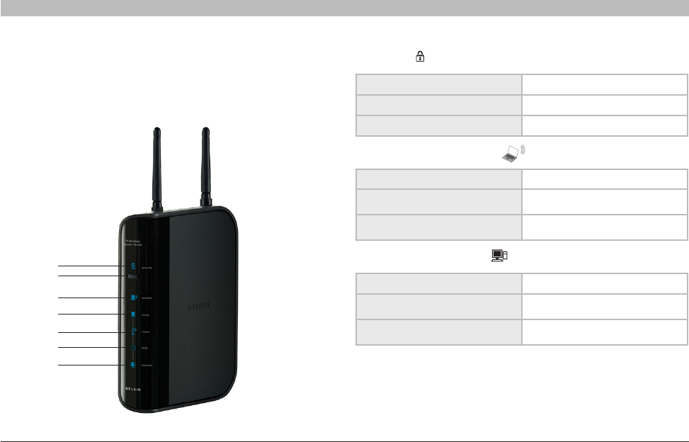
2. Wireless-Computer Status
The Router has been designed to be placed on a desktop. All of the
cables exit from the rear of the Router for better organization and utility.
The Network Status Display is easily visible on the FRONT of the Router
to provide you with information about network activity and status. See
the Network Status Display Guide for more detailed information.
1. Security
OFF Wireless security is OFF
Solid Blue Wireless security is ON
Flashing Blue WPS sync is in progress
OFF Wireless computer is not present
Solid Blue Wireless computer is connected
to the Router
Blinking Amber Problem with wireless computer
connecting properly to the Router
OFF Wired computer is not present
Solid Blue Wired computer is connected to
the Router
Blinking Amber Problem with wired computer
connecting to the Router currently
3. Wired-Computer Status
1.
2.
3.
4.
5.
6.
7.
11
N Wireless Modem Router
SECTIONSTable of Contents 12 45678910
3
KNOWING YOUR MODEM ROUTER
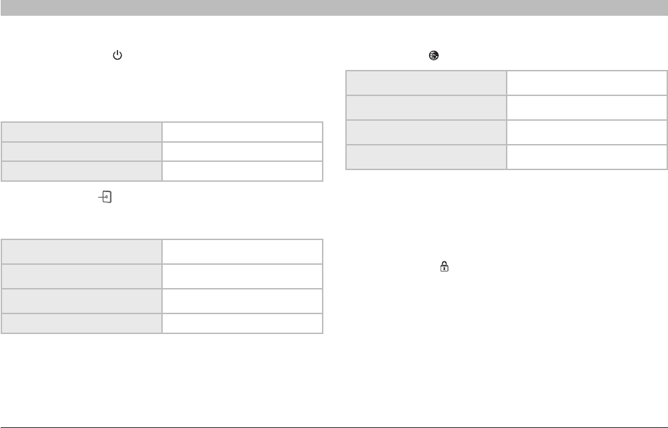
5. ADSL Line Status
This icon lights in blue to indicate that your Router is connected properly
to the ADSL. It turns amber when problem is detected.
4. Router/Power Status
When you apply power to the Router or restart it, a short period of time
elapses while the Router boots up. During this time, the “router” icon
blinks. When the Router has completely booted up, the “router” icon
becomes a solid light, indicating the Router is ready for use.
6. Internet Status
OFF Router is off
Blinking Blue Router is booting up
Solid Blue Router is on and ready
OFF Router is NOT connected to
the Internet
Blinking Blue Router is attempting to
connect to the Internet
Solid Blue Router is connected to
the Internet
Blinking Amber Router is not connected to
the Internet
OFF Router is NOT connected to a
functioning ADSL line
Blinking Blue Router is attempting to connect to
the ADSL line
Solid Blue Router is connected to an ADSL
service and is functioning properly
Blinking Amber Problem with ADSL line
This unique icon shows you when the Router is connected to the
Internet. When the light is off, the Router is NOT connected to the
Internet. When the light is blinking amber, the Router is attempting
to connect to the Internet. When the light is solid blue, the Router is
connected to the Internet. When using the “Disconnect after x minutes”
feature, this icon becomes extremely useful in monitoring the status of
your Router’s connection.
7. WPS Push Button
This button is for the Wi-Fi Protected Setup™ feature. Refer to the
“Changing the Wireless Security Settings” section for more details.
12
N Wireless Modem Router
SECTIONSTable of Contents 12 45678910
3
KNOWING YOUR MODEM ROUTER
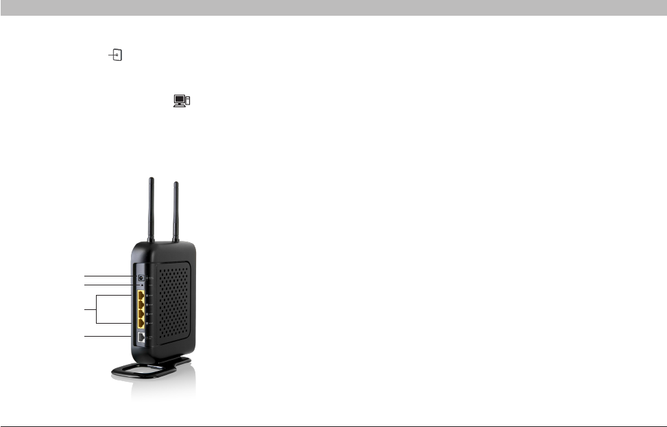
8. Connection to ADSL – Gray
This port is for connection to your ADSL. Connect your ADSL to this
port. An RJ11 telephone cord is provided in the package.
9. Connections to Wired Computers – Yellow
Connect your wired (non-wireless) computers to these ports. These
ports are RJ45, 10/100 auto-negotiation, auto-uplinking ports for
standard UTP category 5 or 6 Ethernet cable. The ports are labeled 1
through 4, with onboard LEDs on the connectors.
10. Reset Button
The “Reset” button is used in rare cases when the Router may function
improperly. Resetting the Router will restore the Router’s normal
operation while maintaining the programmed settings. You can also
restore the factory default settings by using the “Reset” button. Use the
restore option in instances where you may have forgotten your custom
password.
i. Resetting the Router
Push and release the “Reset” button. The lights on the Router will
momentarily flash. The “Router” light will begin to blink. When the
“Router” light becomes solid again, the reset is complete.
ii. Restoring the Factory Defaults
Press and hold the “Reset” button for at least 10 seconds, then
release it. The lights on the Router will momentarily flash. The
“Router” light will begin to blink. When the “Router” light becomes
solid again, the restore is complete.
11. Power Jack – Black
Connect the included 12V/1A DC power supply to this jack.
8
10
11
9

13
N Wireless Modem Router
SECTIONSTable of Contents 123 5678910
CONNECTING AND CONFIGURING YOUR MODEM ROUTER
4
Verify the contents of your box. You should have the following:
• Belkin N Wireless Modem Router
• RJ11 Telephone Cord
• RJ45 Ethernet Networking Cable
• Power Supply
• Belkin Setup Assistant Software CD
• User Manual on CD
• Micro Filter (if your ISP line requires)
• Quick Installation Guide
• Security Guide
• Network Status Display Guide
Setup Assistant
Belkin has provided our Setup Assistant software to make installing your
Router a simple and easy task. You can use it to get your Router up and
running in minutes. The Setup Assistant requires that your Windows
2000 or XP computer be connected directly to your ADSL and that the
Internet connection is active and working at the time of installation.
If it is not, you must use the “Alternate Setup Method” section of this
User Manual to configure your Router. Additionally, if you are using an
operating system other than Windows 2000, XP, or Vista, or Mac OS X
v10.4 and v10.5, you must set up the Router using the “Alternate Setup
Method” section of this User Manual.
14
N Wireless Modem Router
SECTIONSTable of Contents 123 5678910
4
CONNECTING AND CONFIGURING YOUR MODEM ROUTER
2
1
4
5
3
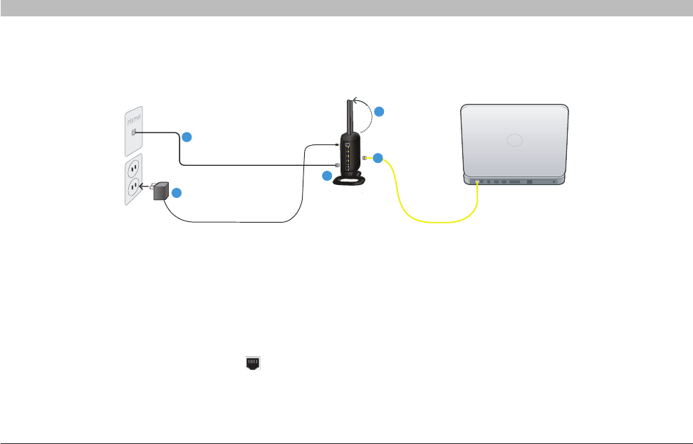
1.1 Brand-New Setup
Follow these steps if you are not replacing an existing modem. If you are
replacing an existing modem, skip to the next section, “Replacing an
Existing Modem or Modem Router”, starting on page 15.
1. Unpack your new Router from the box and place it next to your
computer. Raise the Router’s antennas.
2. Retrieve the yellow RJ45 cable that was included with your
Router. First, connect one end to any yellow port labeled “Wired”
on the back of your Router. Then, connect the other end to the
networking port on the back of your computer.
3. Retrieve the included gray RJ11 phone cord. Connect one end to
the gray port labeled “ADSL line” on the back of your Router. Then
connect the other end to your ADSL connection (either a wall jack
or an ADSL splitter).
Note: Some ADSL connections require a micro filter. Your ADSL provider
can tell you if you need one. Belkin includes a micro filter in regions
known to use them. You may or may not have received one in your box.
4. Plug your Router’s power supply into the black port labeled
“Power” on the back of your Router.
5. Wait 20 seconds for the Router to start up. Look at the display on
the front of the Router. Make sure the “Wired” and “Router” icons
are lit up in blue. If they are not, recheck your connections.
Step 1: Hardware Connections
15
N Wireless Modem Router
SECTIONSTable of Contents 123 5678910
4
CONNECTING AND CONFIGURING YOUR MODEM ROUTER
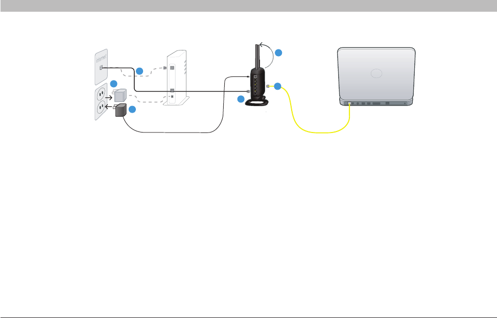
1.2 Replacing an Existing Modem or Modem Router
Follow these steps if you currently have a modem or a modem router
that you will be replacing with your new Router.
Important: Please unplug the power adapter of your old modem from
your wall outlet first.
1. Unpack your new Router from the box and place it next to
your old modem. Raise the Router’s antennas. Unplug your old
modem’s power cord.
2. Locate the cable that connects your old modem to your computer.
Unplug that cable from your old modem, and plug it into any
yellow port labeled “Wired” on the back of your new Router.
3. Locate the cable that connects your old modem to the ADSL wall
jack. Unplug it from your old modem and then connect it to the
gray port labeled “ADSL line” on the back of your Router.
4. Plug your Router’s power supply into the black port labeled
“Power” on the back of your Router.
5. Wait 20 seconds for the Router to start up. Look at the display on
the front of the Router. Make sure the “Wired” and “Router” icons
are lit in blue. If they are not, recheck your connections.
2
1
5
3
1
4
LA
N
ADSL
16
N Wireless Modem Router
SECTIONSTable of Contents 123 5678910
4
CONNECTING AND CONFIGURING YOUR MODEM ROUTER
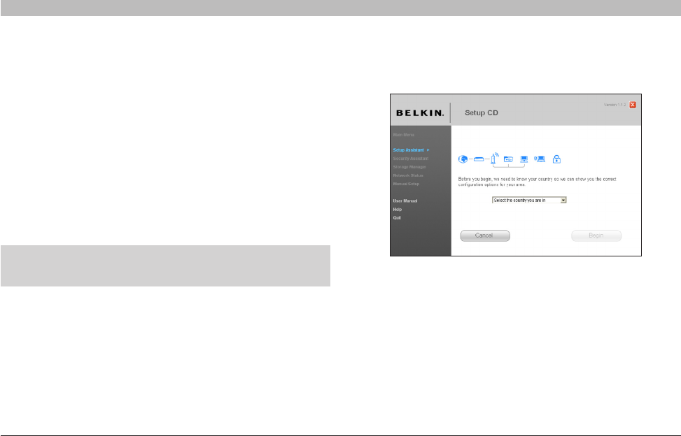
Select Country
Select your country from the drop-down box. Click “Begin” to continue.
Step 2: Set Up the Router – Run the Setup Assistant Software
1. Shut down any programs that are running on your computer
at this time.
Turn off any firewall or Internet-connection-sharing software on
your computer.
2. Insert the CD into your computer. The Setup Assistant will
automatically appear on your computer’s screen within
15 seconds. Click on “Setup Assistant” to run the Setup
Assistant. Follow the instructions there.
Note for Windows Users: If the Setup Assistant does not start
up automatically, select your CD-ROM drive from “My Computer”
and double-click on the file named “SetupAssistant” to start the
Setup Assistant.
IMPORTANT: Run the Setup Assistant from the computer that is
directly connected to the Router from Step 1.1B.
Note to US model owner: To comply with US FCC regulation, the country
selection function has been completely removed from all US models. The
above function is for non-US models only.
17
N Wireless Modem Router
SECTIONSTable of Contents 123 5678910
4
CONNECTING AND CONFIGURING YOUR MODEM ROUTER
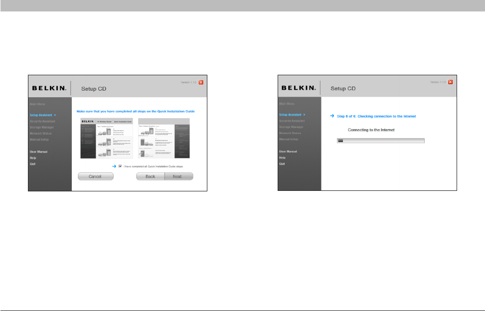
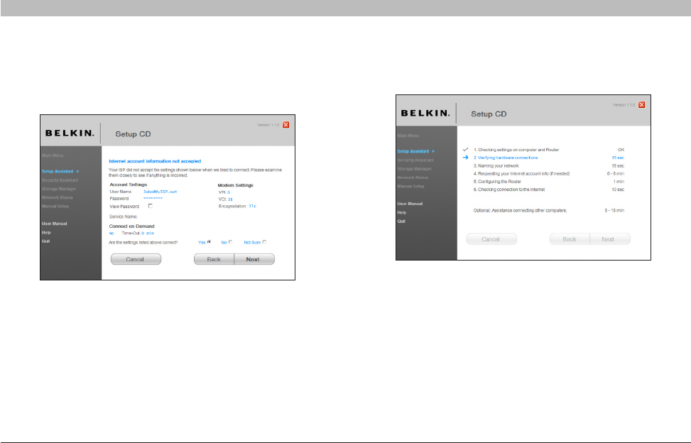
Progress Screen
Setup Assistant will show you a progress screen each time a step in the
setup has been completed.
Confirmation Screen
Verify that you have completed all QIG steps by checking the box to the
right of the arrow. Click “Next” to continue.
18
N Wireless Modem Router
SECTIONSTable of Contents 123 5678910
4
CONNECTING AND CONFIGURING YOUR MODEM ROUTER
2.2 Verifying Hardware Connections
The Setup Assistant will now verify your hardware connection.
2.1 Checking Settings
The Setup Assistant will now examine your computer’s network settings
and gather information needed to complete the Router’s connection to
the Internet.
19
N Wireless Modem Router
SECTIONSTable of Contents 123 5678910
4
CONNECTING AND CONFIGURING YOUR MODEM ROUTER
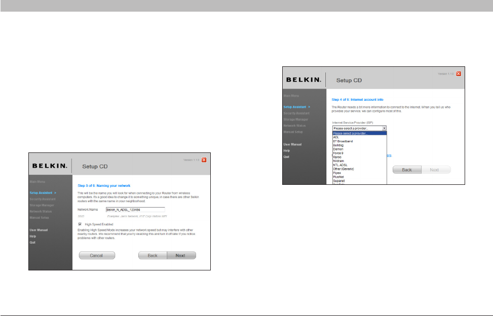
2.4 Requesting Internet Account Info (if needed)
Select your ISP from the drop-down boxes.
2.3 Naming your Wireless Network
The Setup Assistant will display the default wireless network name or
Service Set Identifier (SSID). This is the name of your wireless network
to which your computers or devices with wireless network adapters
will connect. You can either use the default or change it to something
unique. Write down this name for future reference.
If the Router is capable of “High Speed Mode”, this option will be
checked. You can turn off this option later using the Bandwidth Switch
described in this User Manual (see page 44). Click “Next” to continue.
20
N Wireless Modem Router
SECTIONSTable of Contents 123 5678910
4
CONNECTING AND CONFIGURING YOUR MODEM ROUTER
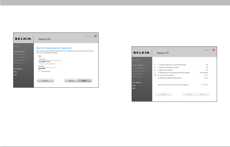
2.5 Configuring the Router
The Setup Assistant will now configure your Router by sending data to
the Router and restarting it. Wait for the on-screen instructions.
Note: Do not disconnect any cable or power off the Router while the
Router is rebooting. Doing so will render your Router inoperable.
If your Internet account requires a login and password, you will be
prompted with a screen similar to the illustration below. Click “Next”
to continue.
21
N Wireless Modem Router
SECTIONSTable of Contents 123 5678910
4
CONNECTING AND CONFIGURING YOUR MODEM ROUTER
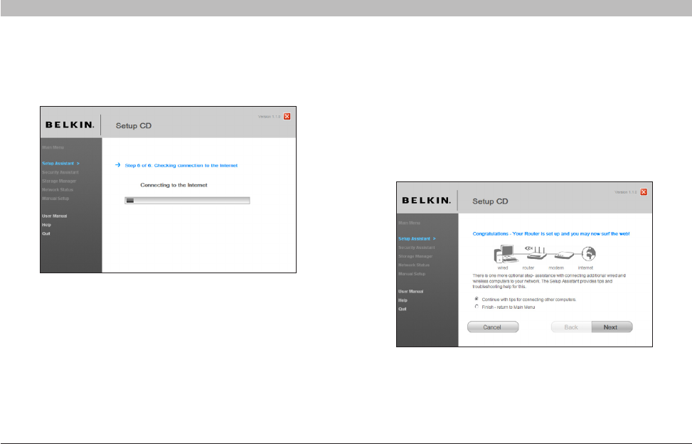
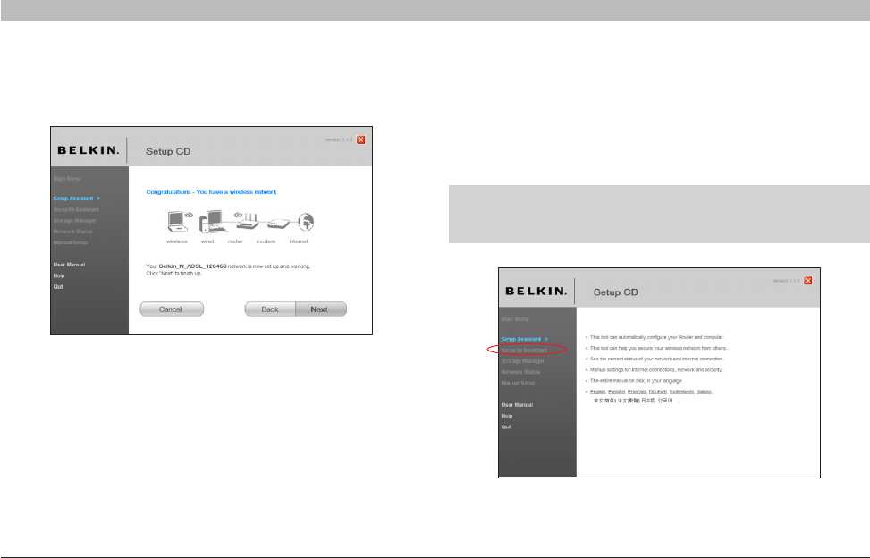
Congratulations
You have finished installing your new Belkin Router. You will see
the Congratulations screen when your Router can connect to the
Internet. You can begin surfing by opening your browser and going
to any website.
You can use the Setup Assistant to set up your other wired and
wireless computers to connect to the Internet by clicking “Next”. If
you decide to add computers to your Router later, select “Finish—
return to Main Menu” and then click “Next”.
2.6 Checking Internet Connection
We are almost done. The Setup Assistant will now check your
connection to the Internet.
22
N Wireless Modem Router
SECTIONSTable of Contents 123 5678910
4
CONNECTING AND CONFIGURING YOUR MODEM ROUTER
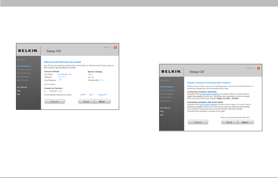
2.7 Optional: Assistance Connecting Other Computers
This optional step will help you to connect additional wired and wireless
computers to your network. Follow the on-screen instructions.
Troubleshooting
If the Setup Assistant is not able to connect to the Internet, you will see the following screen. Follow the on-screen instructions to go through the
troubleshooting steps.
23
N Wireless Modem Router
SECTIONSTable of Contents 123 5678910
4
CONNECTING AND CONFIGURING YOUR MODEM ROUTER
Step 3: Set Up Wireless Security – Run the Security Assistant Software
Now that your network is set up and working, it is recommended that
you turn on wireless security to prevent unauthorized access to your
network from neighboring wireless-enabled computers. The Security
Assistant will guide you through the process. Click “Security Assistant”
and follow the on-screen instructions.
Once you have verified that your other wired and wireless computers are
properly connected, your network is set up and working. You can now
surf the Internet. Click “Next” to return to the main menu.
IMPORTANT: Run the Setup Assistant from the computer that is
directly connected to the Router from Steps 1.1B and 1.2B.
24
N Wireless Modem Router
SECTIONSTable of Contents 123 5678910
4
CONNECTING AND CONFIGURING YOUR MODEM ROUTER
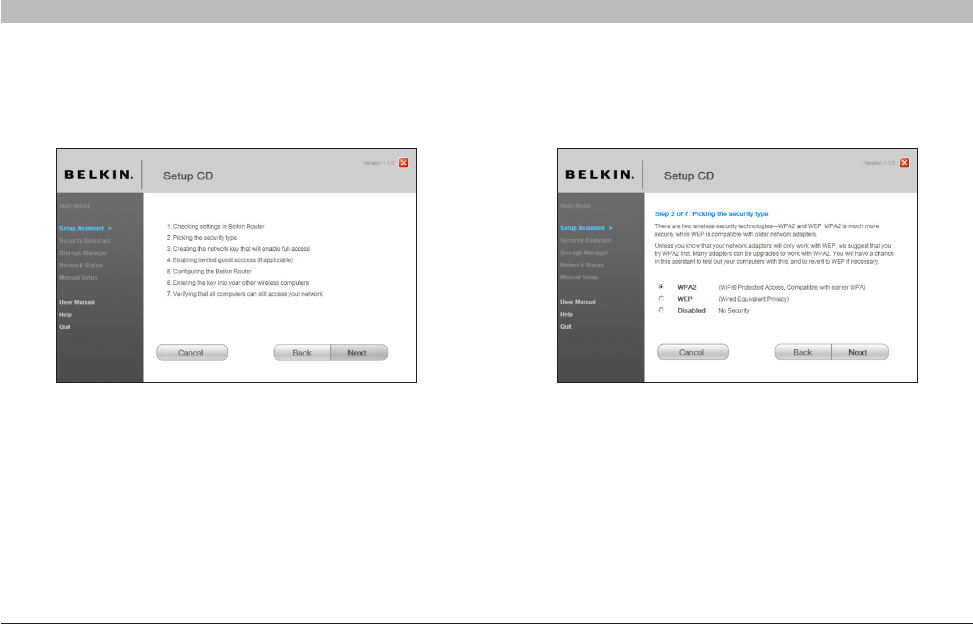
3.1 Picking the Security Type
Select the security type for your wireless network and click “Next”
to continue.
Progress Screen
The Security Assistant will show you a progress screen each time a step
has been completed.
25
N Wireless Modem Router
SECTIONSTable of Contents 123 5678910
4
CONNECTING AND CONFIGURING YOUR MODEM ROUTER
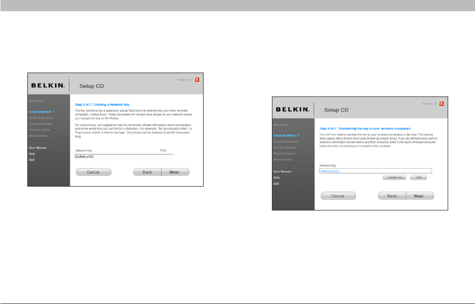
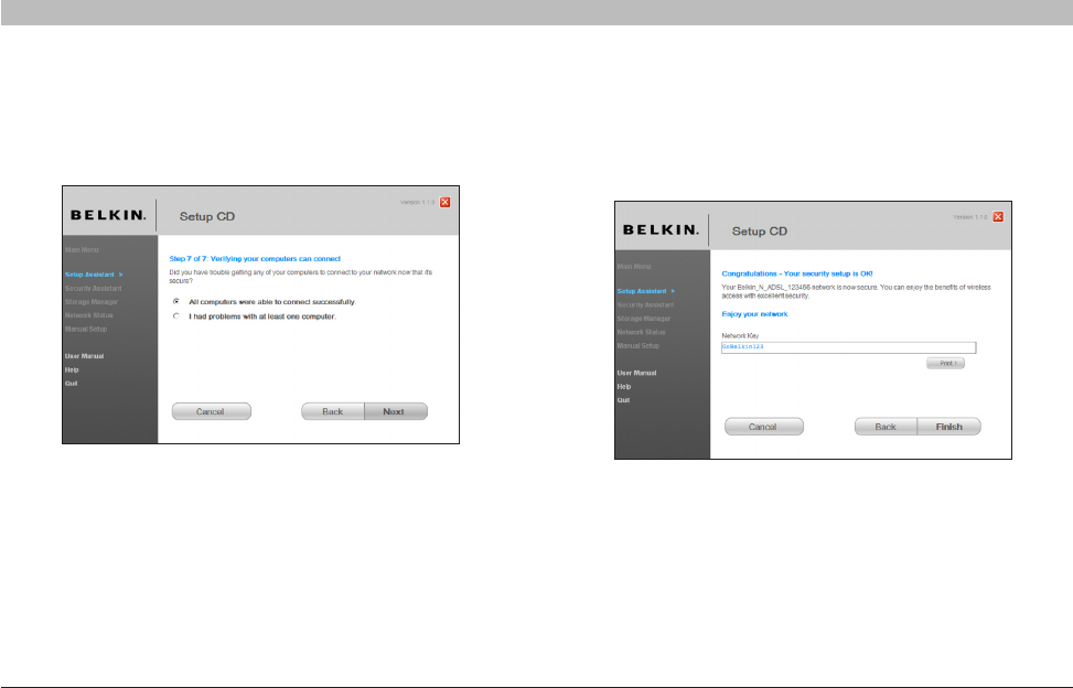
3.3 Transferring the Key
After setting up your wireless security, you will have to transfer the
network key to each of your wireless computers. Click on “Transfer Key”
if you have a USB flash drive. Follow the on-screen instructions, or click
on “Print” to print the information. Manually enter it to each wireless
computer. Then, click “Next” to continue.
3.2 Creating a Network Key
Enter a network key (PSK) for your wireless network and click “Next”
to continue.
26
N Wireless Modem Router
SECTIONSTable of Contents 123 5678910
4
CONNECTING AND CONFIGURING YOUR MODEM ROUTER
Congratulations
Once you have verified that your wireless computers are properly
connected, your wireless network is set up and secured. You now can
run your network wirelessly and securely. Click “Finish” to take you back
to the main menu.
3.4 Verifying the Connection
If all your wireless computers are able to connect to the Router, click
“Next”. If you are having trouble, select “I had problem with at least one
computer” and click “Next”. Then, follow on-screen instructions.
27
N Wireless Modem Router
SECTIONSTable of Contents 1234 678910
ALTERNATE SETUP METHOD
5
Step 1: Hardware Connections – Follow the Quick Installation Guide
See the QIG or Step 1: Hardware Connections from the previous section.
Step 2: Set your Computer’s Network Settings to Work with a DHCP Server
See the section in this User Manual called “Manually Configuring Network Settings” for directions.
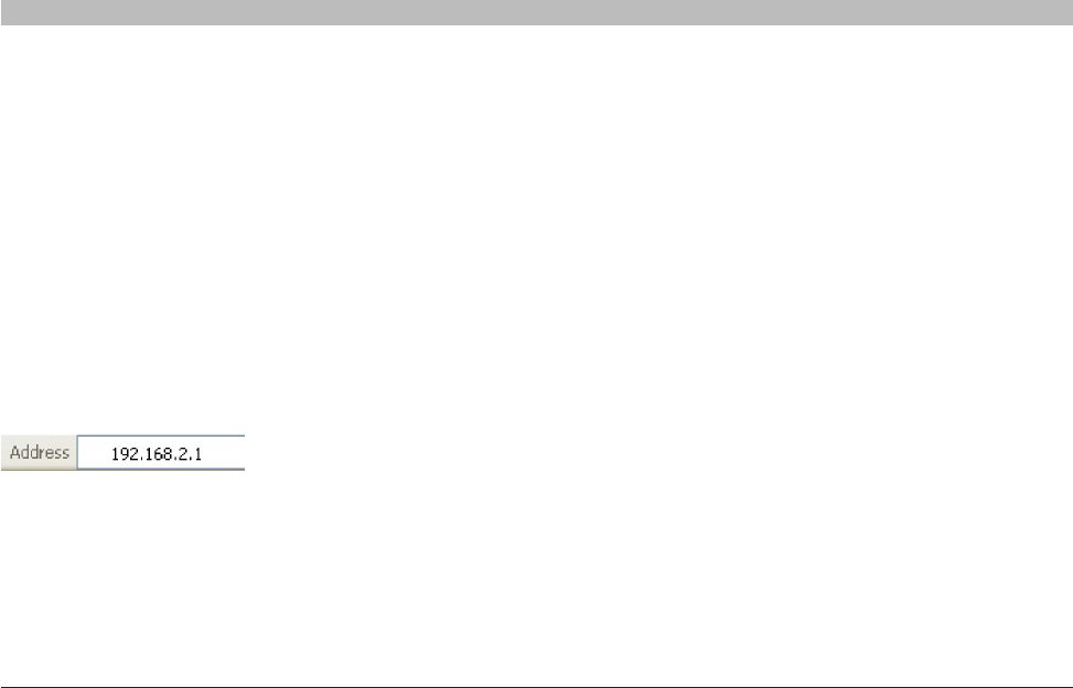
Step 3: Configuring the Router Using the Web-Based Advanced User Interface
Using your Internet browser, you can access the Router’s Web-Based
Advanced User Interface. In your browser, type “192.168.2.1” (do not type in
anything else such as “http://” or “www”). Then press the “Enter” key.
28
N Wireless Modem Router
SECTIONSTable of Contents 1234 678910
5
ALTERNATE SETUP METHOD
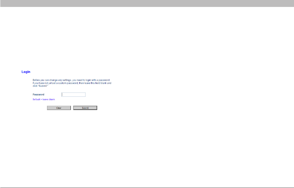
Logging into the Router
You will see the Router’s home page in your browser window. The
home page is visible to any user who wants to see it. To make any
changes to the Router’s settings, you have to log in. Clicking the
“Login” button or clicking on any one of the links on the home page
will take you to the login screen. The Router ships with no password
entered. In the login screen, leave the password blank and click the
“Submit” button to log in.
Logging out of the Router
One computer at a time can log into the Router for the purposes of
making changes to the settings of the Router. Once a user has logged in
to make changes, there are two ways that the computer can be logged
out. Clicking the “Logout” button will log the computer out. The second
method is automatic. The login will time out after a specified period of
time. The default login time-out is 10 minutes. This can be changed from
one to 99 minutes. For more information, see the section in this manual
titled “Changing the Login Time-Out Setting”.
29
N Wireless Modem Router
SECTIONSTable of Contents 1234 678910
5
ALTERNATE SETUP METHOD
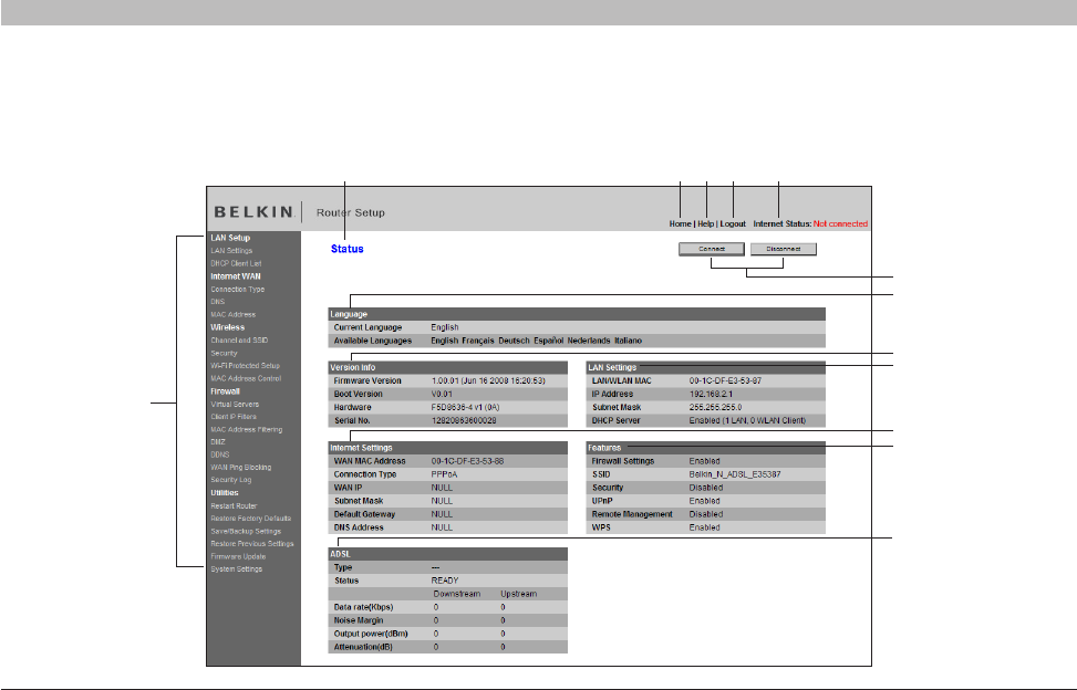
Understanding the Web-Based Advanced User Interface
The home page is the first page you will see when you access the Advanced User Interface (UI). The home page shows you a quick view of the
Router’s status and settings. All advanced setup pages can be reached from this page.
(2)(13) (3) (4) (5)
(6)
(7)
(8)
(9)
(10)
(11)
(12)
(1)

30
N Wireless Modem Router
SECTIONSTable of Contents 1234 678910
5
ALTERNATE SETUP METHOD
6. Connect/Disconnect Buttons
Use these buttons to manually connect or disconnect your ADSL
connection as needed.
7. Language
Shows the active language for the Advanced User Interface. Select a
desirable language by clicking one of the available languages.
8. Version Info
Shows the firmware version, boot version, hardware version, and serial
number of the Router.
9. LAN Settings
Shows you the settings of the Local Area Network (LAN) side of the
Router. Changes can be made to the settings by clicking on any one
of the links (IP Address, Subnet Mask, DHCP Server) or by clicking the
“LAN” quick-navigation link on the left side of the screen.
10. Internet Settings
Shows the settings of the Internet/WAN side of the Router that
connects to the Internet. Changes to any of these settings can be made
by clicking on the links or by clicking on the “Internet/WAN” quick-
navigation link on the left side of the screen.
11. Features
Shows the status of the Router’s firewall, wireless, and UPnP, Remote
Management features. Changes can be made to the settings by clicking
on any one of the links or by clicking the quick-navigation links on the
left side of the screen.
1. Quick-Navigation Links
You can go directly to any of the Router’s advanced UI pages by clicking
directly on these links. The links are divided into logical categories and
grouped by tabs to make finding a particular setting easier to find.
Click in the header (Marked in bold) of each tab and it will show you a
short description of the tab’s function..
2. Home Button
The home button is available in every page of the UI. Pressing this
button will take you back to the home page.
3. Help Button
The “Help” button gives you access to the Router’s help pages. Help
is also available on many pages by clicking “more info” next to certain
sections of each page.
4. Login/Logout Button
This button enables you to log in and out of the Router with the press of
one button. When you are logged into the Router, this button will change
to read “Logout”. Logging into the Router will take you to a separate
login page where you will need to enter a password. When you are
logged into the Router, you can make changes to the settings. When you
are finished making changes, you can log out of the Router by clicking
the “Logout” button. For more information about logging into the Router,
see the section called “Logging into the Router”.
5. Internet-Status Indicator
This indicator is visible in all pages of the Router, indicating the
connection status of the Router. When the indicator says “Connected”
in blue, the Router is connected to the Internet. When the Router is not
connected to the Internet, the indicator will read “Not Connected” in
RED. The indicator is automatically updated when you make changes to
the settings of the Router.
31
N Wireless Modem Router
SECTIONSTable of Contents 1234 678910
5
ALTERNATE SETUP METHOD
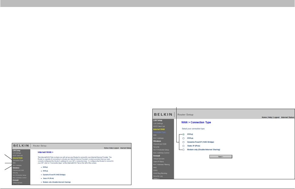
Connection Type
From the “Connection Type” page, you can select one of these five
connection types based on the instruction provided by your ISP:
• PPPoE
• PPPoA
• Dynamic/FixedIP(1483Bridged)
• StaticIP(IPoA)
• ModemOnly(DisableInternetSharing)
Select the type of connection you use by clicking the radio button (1)
next to your connection type and then clicking “Next”
(1)
12. ADSL Info
Shows the ADSL status and transmission rates.
13. Page Name
The page you are on can be identified by this name. This User Manual
will sometimes refer to pages by name. For instance “LAN > LAN
Settings” refers to the “LAN Settings” page.
Step 4: Configuring your Router for Connection to your Internet
Service Provider (ISP)
The “Internet/WAN” tab is where you will set up your Router to connect
to your Internet Service Provider (ISP). The Router is capable of
connecting to virtually any ISP’s system provided you have correctly
configured the Router’s settings for your ISP’s connection type. Your
ISP connection settings are provided to you by your ISP. To configure
the Router with the settings that your ISP gave you, click “Connection
Type” (A) on the left side of the screen. Select the connection type you
use. If your ISP gave you DNS settings, clicking “DNS” (B) allows you
to enter DNS address entries for ISPs that require specific settings.
Clicking “MAC Address” (C) will let you clone your computer’s MAC
address or type in a specific WAN MAC address, if required by your ISP.
When you have finished making settings, the “Internet Status” indicator
will read “connection OK” if your Router is set up properly.
A
B
C
32
N Wireless Modem Router
SECTIONSTable of Contents 1234 678910
5
ALTERNATE SETUP METHOD
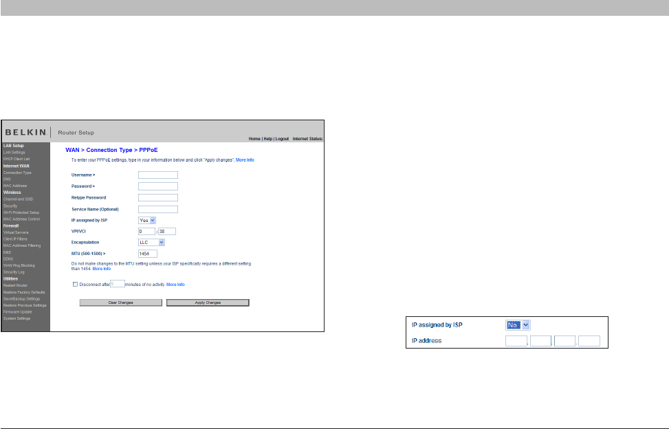
1. User Name – Enter the user name. (Assigned by your ISP).
2. Password – Enter your password. (Assigned by your ISP).
3. Retype Password – Confirm the password. (Assigned by your ISP).
4. Service Name (Optional) – A service name is rarely required by an
ISP. If you are not sure if your ISP requires a service name, leave
this blank.
5. IP assigned by ISP
1) For the Dynamic IP connection – Select “Yes” if your ISP
instructed you to use Dynamic IP.
2) For the Static IP connection – Select “No” if your ISP
instructed you to use Static IP.
– IP Address – Enter an IP address assigned by your ISP for the
Router WAN interface.
Setting your ISP Connection Type to PPPoE or PPPoA
PPPoE (Point-to-Point Protocol over Ethernet) is the standard method of connecting networked devices. It requires a user name and password to
access the network of your ISP for connecting to the Internet. PPPoA (PPP over ATM) is similar to PPPoE, but is mostly implemented in the UK.
Select PPPoE or PPPoA and click “Next”. Then enter the information provided by your ISP, and click “Apply Changes” to activate your settings.
33
N Wireless Modem Router
SECTIONSTable of Contents 1234 678910
5
ALTERNATE SETUP METHOD
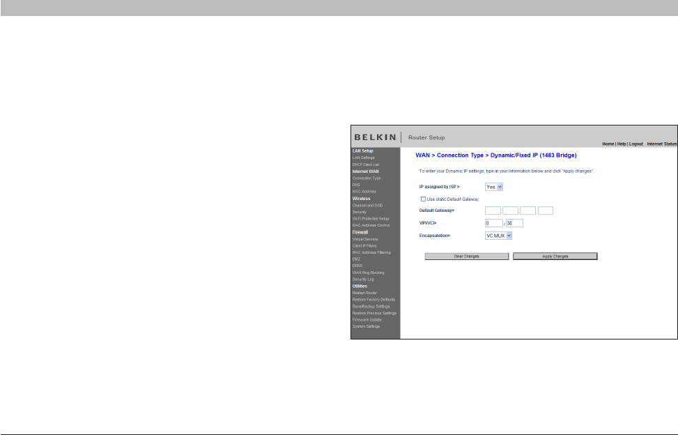
Setting your Connection Type to Dynamic/Fixed IP (1483 Bridged)
This connection method bridges your network and ISP’s network
together. The Router can obtain an IP address automatically from your
ISP’s DHCP server or accept a fixed IP address assigned by your ISP.
6. VPI/VCI – Enter your Virtual Path Identifier (VPI) and Virtual Circuit
Identifier (VCI) parameter here. (Assigned by your ISP).
7. Encapsulation – Select your encapsulation type (supplied by
your ISP) tospecify how to handle multiple protocols at the ATM
transport layer.
VC-MUX: PPPoA Virtual Circuit Multiplexer (null encapsulation) allows
only one protocol running per virtual circuit with fewer overheads.
LLC: PPPoA Logical Link Control allows multiple protocols running
over one virtual circuit (more overhead).
8. MTU – Enter the MUT value for your ISP.
9. Disconnect after of x minutes of no activity – Checking the box
and enter the number of minute that you want the modem router to
auto disconnect after no activity. After this time has been exceeded,
the connection will be terminated.
Click “Apply Changes” to save and activate your settings. To go back
to the original settings before saving, click “Clear Changes”. Or click
any of the Quick-Navigation links for other options. Your new settings
will not be saved unless your click “Apply Changes”.
34
N Wireless Modem Router
SECTIONSTable of Contents 1234 678910
5
ALTERNATE SETUP METHOD
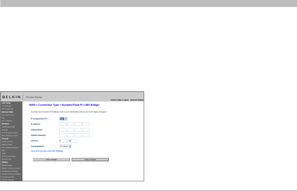
For Static IP connection:
1. IP assigned by ISP – Select “No” if your ISP instructed you to use
fixed IP.
2. IP Address – Enter an IP address assigned by your ISP for the Router
WAN interface.
3. Subnet Mask – Enter a subnet mask assigned by your ISP.
4. Default Gateway – Enter a default gateway IP address assigned by
your ISP.
5. VPI/VCI – Enter your Virtual Path Identifier (VPI) and Virtual Circuit
Identifier (VCI) parameters here. These identifiers are assigned by
your ISP.
6. Encapsulation – Select the LLC or VC MUX your ISP uses.
Click “Apply Changes” to save and activate your settings. To go back to
the original settings before saving, click “Clear Changes”. Or click any of
the Quick-Navigation links for other options. Your new settings will not
be saved unless your click “Apply Changes”.
For Dynamic IP connection:
1. IP assigned by ISP – Select “Yes” if your ISP instructed you to use
Dynamic IP.
2. VPI/VCI – Enter your Virtual Path Identifier (VPI) and Virtual Circuit
Identifier (VCI) parameter here. These identifiers are assigned by
your ISP.
3. Encapsulation – Select LLC or VC MUX your ISP uses.
Click “Apply Changes” to save and activate your settings. To go back
to the original settings before saving, click “Clear Changes”; or click
any of the Quick-Navigation links for other options. Your new settings
will not be saved unless you click “Apply Changes”.
35
N Wireless Modem Router
SECTIONSTable of Contents 1234 678910
5
ALTERNATE SETUP METHOD
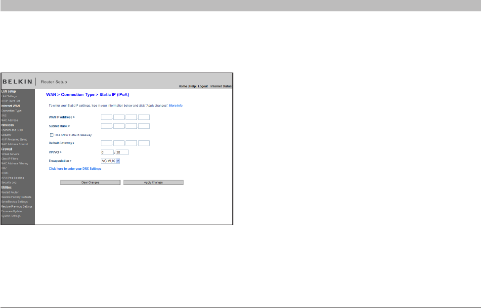
1. WAN IP Address – Enter an IP address assigned by your ISP for the
Router WAN interface.
2. Subnet Mask – Enter a subnet mask assigned by your ISP.
3. Use Static Default Gateway – Enter a default gateway IP address.
If the Router cannot find the destination address within its local
network, it will forward the packets to the default gateway assigned
by your ISP.
4. VPI/VCI – Enter your Virtual Path Identifier (VPI) and Virtual Circuit
Identifier (VCI) parameter here. These identifiers are assigned by
your ISP.
5. Encapsulation – Select LLC or VC MUX your ISP uses.
Click “Apply Changes” to save and activate your settings. To go back
to the original settings before saving, click “Clear Changes”. Or click
any of the Quick-Navigation links for other options. Your new settings
will not be saved unless your click “Apply Changes”.
Setting your ISP Connection Type to Static IP (IPoA)
This connection type is also called “Classical IP over ATM” or “CLIP”, which your ISP provides a fixed IP for your Router to connect to the Internet.
36
N Wireless Modem Router
SECTIONSTable of Contents 1234 678910
5
ALTERNATE SETUP METHOD
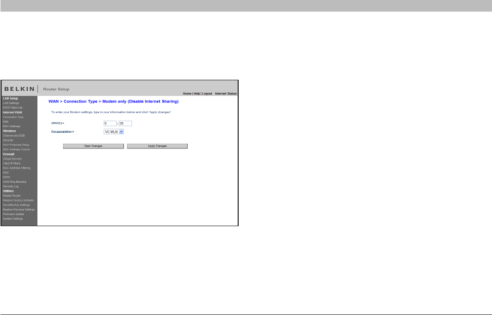
1. VPI/VCI – Enter your Virtual Path Identifier (VPI) and Virtual Circuit
Identifier (VCI) parameters here. (Assigned by your ISP).
2. Encapsulation – Select the LLC or VC MUX your ISP uses.
Click “Apply Changes” to save and activate your settings. To go back to
the original settings before saving, click “Clear Changes”. Or click any of
the Quick-Navigation links for other options. Your new settings will not
be saved unless your click “Apply Changes”.
Setting your Connection Type to Modem Only (Disable Internet Sharing)
In this mode, the Router simply acts as a bridge passing packets across the DSL port. It requires additional software to be installed on your
computers in order to access the Internet.
37
N Wireless Modem Router
SECTIONSTable of Contents 1234 678910
5
ALTERNATE SETUP METHOD
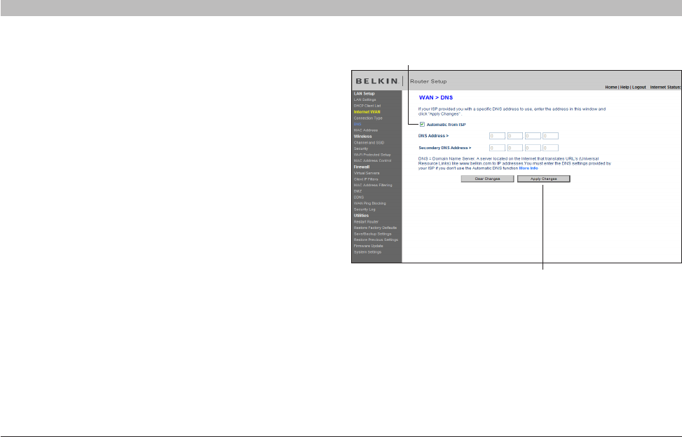
Setting Custom Domain Name Server (DNS) Settings
A “Domain Name Server” is a server located on the Internet that
translates Universal Resource Locaters (URLs) like “ belkin.com” to
IP addresses. Many Internet Service Providers (ISPs) do not require
you to enter this information into the Router. The “Automatic from
ISP” box (1) should be checked if your ISP did not give you a specific
DNS address. If you are using a static IP connection type, then you
may need to enter a specific DNS address and secondary DNS
address for your connection to work properly. If your connection
type is dynamic or PPPoE, it is likely that you do not have to enter
a DNS address. Leave the “Automatic from ISP” box checked. To
enter the DNS address settings, uncheck the “Automatic from ISP”
box and enter your DNS entries in the spaces provided. Click “Apply
Changes” (2) to save the settings
(1)
(2)
38
N Wireless Modem Router
SECTIONSTable of Contents 12345 78910
USING THE WEB-BASED ADVANCED USER INTERFACE
6
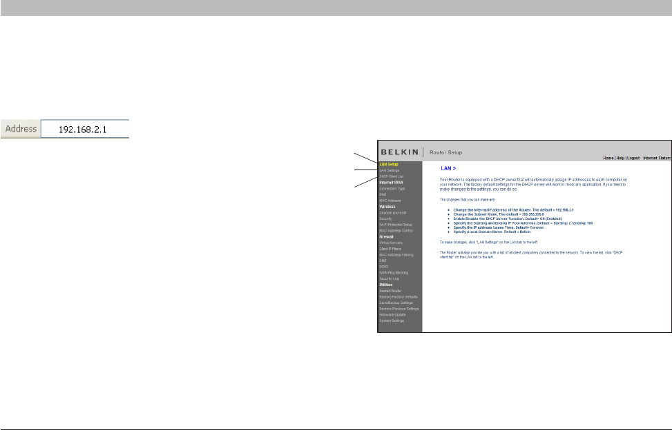
Viewing the LAN Settings
Clicking on the header of the LAN tab (1) will take you to the LAN tab’s
header page. A quick description of the functions can be found here. To
view the settings or make changes to any of the LAN settings, click on
“LAN Settings” (2) or to view the list of connected computers, click on
“DHCP client list” (3).
(2)
(1)
(3)
Using your Internet browser, you can access the Router’s Web-Based
Advanced User Interface. In your browser, type “192.168.2.1” (do
not type in anything else such as “http://” or “www”) then press the
“Enter” key.
You will see the Router’s home page in your browser window.
39
N Wireless Modem Router
SECTIONSTable of Contents 12345 78910
6
USING THE WEB-BASED ADVANCED USER INTERFACE
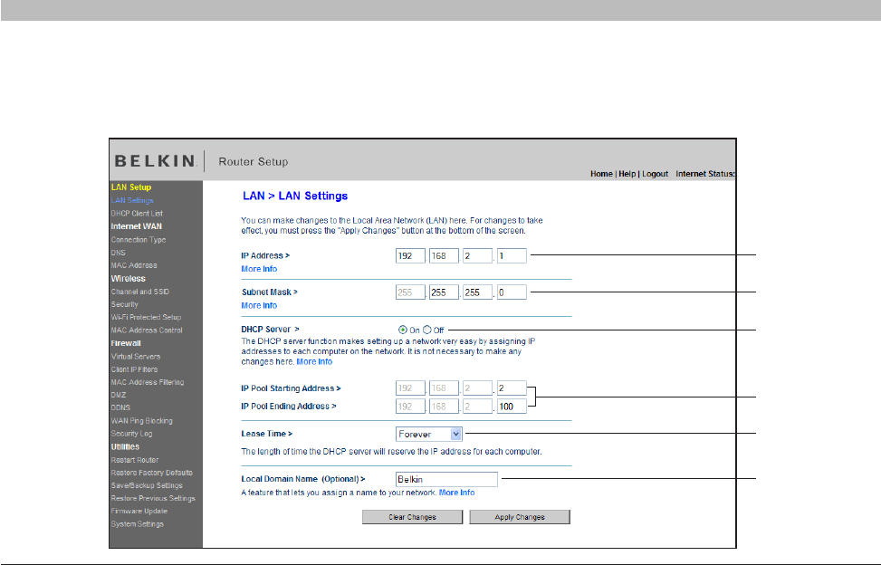
Changing LAN Settings
All settings for the internal LAN setup of the Router can be viewed and changed here.
(1)
(2)
(3)
(4)
(5)
(6)

40
N Wireless Modem Router
SECTIONSTable of Contents 12345 78910
6
USING THE WEB-BASED ADVANCED USER INTERFACE
4. IP Pool
The range of IP addresses set aside for dynamic assignment to the
computers on your network. The default is 2–100 (99 computers). If you
want to change this number, you can do so by entering a new starting
and ending IP address and clicking on “Apply Changes”. The DHCP
server can assign 100 IP addresses automatically. This means that
you cannot specify an IP address pool larger than 100 computers. For
example, starting at 50 means you have to end at 150 or lower so as not
to exceed the 100-client limit. The starting IP address must be lower in
number than the ending IP address.
5. Lease Time
The length of time the DHCP server will reserve the IP address for each
computer. We recommend that you leave the lease time set to “Forever”.
The default setting is “Forever”, meaning that any time a computer is
assigned an IP address by the DHCP server, the IP address will not
change for that particular computer. Setting lease times for shorter
intervals such as one day or one hour frees IP addresses after the
specified period of time. This also means that a particular computer’s
IP address may change over time. If you have set any of the other
advanced features of the Router such as DMZ or client IP filters, these
are dependent on the IP address. For this reason, you will not want the
IP address to change.
6. Local Domain Name (Optional)
The default setting is “Belkin”. You can set a local domain name
(network name) for your network. There is no need to change this setting
unless you have a specific advanced need to do so. You can name the
network anything you want such as “MY NETWORK”.
1. IP Address
The “IP address” is the internal IP address of the Router. The default IP
address is “192.168.2.1”. To access the advanced setup interface, type
this IP address into the address bar of your browser. This address can
be changed if needed. To change the IP address, type in the new IP
address and click “Apply Changes”. The IP address you choose should
be a non-routable IP. Examples of a non-routable IP are:
192.168.x.x (where x is anything between 0 and 255)
10.x.x.x (where x is anything between 0 and 255)
2. Subnet Mask
There is no need to change the subnet mask. It is possible to change
the subnet mask if necessary; however, do NOT make changes to the
subnet mask unless you have a specific reason to do so. The default
setting is “255.255.255.0”.
3. DHCP Server
The DHCP server function makes setting up a network very easy by
assigning IP addresses to each computer on the network automatically.
The default setting is “On”. The DHCP server can be turned OFF if
necessary; however, in order to do so you must manually set a static
IP address for each computer on your network. To turn off the DHCP
server, select “Off” and click “Apply Changes”.
41
N Wireless Modem Router
SECTIONSTable of Contents 12345 78910
6
USING THE WEB-BASED ADVANCED USER INTERFACE
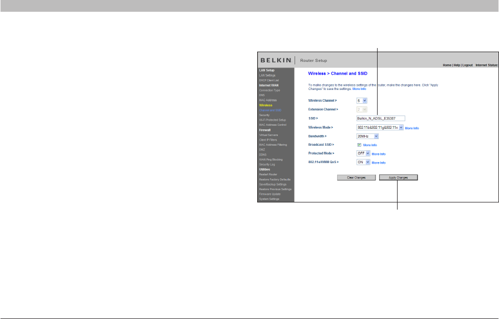
Configuring the Wireless Network Settings
The “Wireless” tab lets you make changes to the wireless network
settings. From this tab you can make changes to the wireless
network name or Service Set Identifier (SSID), operating channel,
encryption security settings, and configure the Router to be used as
an access point.
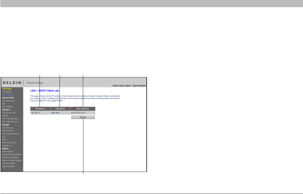
Viewing the DHCP Client List Page
You can view a list of the computers (known as clients), which are
connected to your network. You are able to view the IP address (1) of the
computer, the host name (2) (if the computer has been assigned one),
and the MAC address (3) of the computer’s network interface card (NIC).
Pressing the “Refresh” (4) button will update the list. If there have been
any changes, the list will be updated.
(1) (2) (3)
(4)
42
N Wireless Modem Router
SECTIONSTable of Contents 12345 78910
6
USING THE WEB-BASED ADVANCED USER INTERFACE
Note: Please periodically check for new Router firmware updates
from the “Utilities > Firmware update” page. Newer firmware can fix
problems, add wireless features, and/or improve wireless performance
(see page 66).
Changing the Wireless Network Name (SSID)
To identify your wireless network, a name called the SSID is used. The
SSID is your network name. The default network name of the Router is
“Belkin_N_ADSL_” followed by six digits that are unique to your Router.
Your network name will look something like “Belkin_N_ADSL_123456”.
You can change this to anything you choose, or you can leave it
unchanged. Keep in mind, if you decide to change your wireless network
name, and there are other wireless networks operating in your area, your
network name needs to be different from other wireless networks that
may be operating in your area. To change the SSID, type in the SSID
that you want to use in the SSID field (1) and click “Apply Changes”
(2). The change is immediate. If you make a change to the SSID, your
wireless-equipped computers may also need to be reconfigured to
connect to your new network name. Refer to the documentation of your
wireless network adapter for information on making this change.
(1)
(2)

43
N Wireless Modem Router
SECTIONSTable of Contents 12345 78910
6
USING THE WEB-BASED ADVANCED USER INTERFACE
1) Off
This mode will turn OFF the Router’s access point, so no wireless
devices can join the network. Turning off the wireless function of your
Router is a great way to secure your network when you are away from
home for a long period of time, or don’t want to use the wireless feature
of the Router at a certain time.
2) 802 .11g
Setting the Router to this mode will allow only 802.11g- and
802.11b-compliant devices to join the network. N/draft 802.11n devices
will operate at the 802.11g speed only.
3) 802.11b & 802.11g & 802.11n
Setting the Router to this mode will allow N/draft 802.11n-, 802.11g-, and
802.11b-compliant devices to join the network.
4) 802 .11n
Setting the Router to this mode will allow only N/draft 802.11n-compliant
devices to join the network, keeping out 802.11g and 802.11b devices.
Changing the Wireless Channel
There are a number of operating channels from which you can choose—
in the United Kingdom (and most of Europe), Australia, and most of Asia,
there are 13. In other countries, there are other channel requirements.
Your Router is configured to operate on the proper channels for the
country in which you reside. The channel can be changed if needed. If
there are other wireless networks operating in your area, your network
should be set to operate on a channel that is different than the other
wireless networks.
Extension Channel
The IEEE 802.11n draft specification allows the use of a secondary
channel to double the bandwidth (see the “Using the Bandwidth Switch”
section on the next page). An appropriate extension channel will be
displayed when operating in 40MHz mode (see the “Using the Wireless
Mode Switch” section below). The channel can be changed if necessary.
Using the Wireless Mode Switch
This switch allows you to set the Router’s wireless modes. There are
several modes.
Note: Some modes may require firmware updates to be enabled.

44
N Wireless Modem Router
SECTIONSTable of Contents 12345 78910
6
USING THE WEB-BASED ADVANCED USER INTERFACE
Protected Mode Switch
Protected mode ensures proper operation of N, draft 802.11n-compliant
devices on your wireless network when 802.11g or 802.11b devices
are present or when there is heavy 802.11g or 802.11b traffic in the
operating environment. Use protected mode if your network consists of
a mix of Belkin N Wireless Cards and 802.11g or 802.11b cards on your
network. If you are in an environment that includes little to no 802.11g
or 802.11b wireless network traffic, you will achieve the best N wireless
performance with protected mode OFF. Conversely, in an environment
with HEAVY 802.11g or 802.11b traffic or interference, you will achieve
the best N wireless performance with protected mode ON. This will
ensure N wireless performance is not affected.
802.11e/WMM (Wi-Fi Multimedia™) QoS
WMM, based on 802.11e QoS (Quality of Service), prioritizes important
data on your network, such as multimedia content and voice-over-IP
(VoIP), so it will not be interfered with by other data being sent over the
network. This feature requires other wireless devices, such as Wi-Fi
phones or wireless laptops, to support WMM for best results.
Using the Bandwidth Switch
This switch allows you to set the Router’s wireless bandwidth modes.
There are several modes available:
1) 20MHz/40MHz
Setting the Router to this mode allows it to switch automatically between
20MHz and 40MHz operation. This mode enables 40MHz operation, to
maximize speed for N draft 802.11n-compliant devices when conditions
permit. When a legacy 802.11g access point is presented and occupies
an adjacent secondary channel, the Router automatically reverts to
20MHz operation to maximize compatibility. Set the Router to this mode
for higher performance.
2) 20MHz
Setting the Router to this mode allows only 20MHz operation. This mode
is compatible with N, draft 802.11n-, 802.11g-, and 802.11b-compliant
devices, but will limit N, draft 802.11n-compliant devices’ bandwidth by
half. Reducing bandwidth to 20MHz-only operation might solve some
wireless problems. This is the default mode for the Router.
Using the Broadcast SSID Feature
Note: This advanced feature should be employed by advanced users
only. For security, you can choose not to broadcast your network’s
SSID. Doing so will keep your network name hidden from computers
that are scanning for the presence of wireless networks. To turn off
the broadcast of the SSID, remove the check mark from the box next
to “Broadcast SSID”, and then click “Apply Changes”. The change is
immediate. Each computer now needs to be set to connect to your
specific SSID; an SSID of “ANY” will no longer be accepted. Refer to
the documentation of your wireless network adapter for information on
making this change.
45
N Wireless Modem Router
SECTIONSTable of Contents 12345 78910
6
USING THE WEB-BASED ADVANCED USER INTERFACE
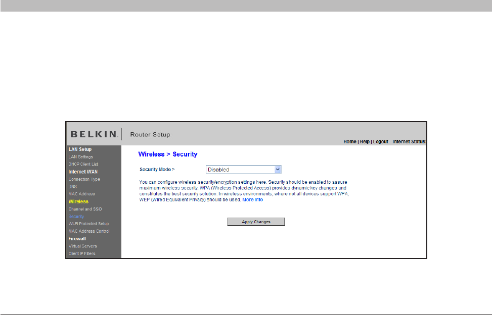
Changing the Wireless Security Settings
Your Router is equipped with the latest security standard called Wi-Fi Protected Access™ 2 (WPA2™) and the legacy security standard called Wired
Equivalent Privacy (WEP). Your Router also supports the Wi-Fi Protected Setup (WPS) specification, which simplifies the setup of a wireless network.
WPS uses familiar methodologies, such as typing in a Personal Identification Number (PIN) or pushing a button, to enable users to automatically
configure network names and strong WPA2 data encryption and authentication. By default, your Router does not ship with security enabled. You may
automatically configure the security settings using WPS. To change the security settings manually, you will need to determine which standard you
want to use. To access the security settings, click “Security” on the “Wireless” tab.
46
N Wireless Modem Router
SECTIONSTable of Contents 12345 78910
6
USING THE WEB-BASED ADVANCED USER INTERFACE
Using Wi-Fi Protected Setup
WPS uses WPA2 (described below) for encryption. It does not provide
additional security, but rather, standardizes the method for securing your
wireless network. You may use either the Push Button Configuration
(PBC) method or PIN method to allow a device access to your wireless
network. Conceptually, the two methods work as follows:
PBC: Push and hold the WPS button located on the front of your
Router for three seconds. Then initiate the WPS procedure on the client
device within two minutes. Refer to your client’s documentation on this
procedure. Pushing the PBC button will automatically enable WPS. The
client has now been securely added to your wireless network.
PIN: The client device has a PIN number (either four or eight digits) that
is associated with WPS. Enable WPS through the GUI shown below.
Enter the client’s PIN into the Router’s internal registrar (accessed
through this GUI). The client will be automatically enrolled into your
wireless network within two minutes.

47
N Wireless Modem Router
SECTIONSTable of Contents 12345 78910
6
USING THE WEB-BASED ADVANCED USER INTERFACE
WPA2 Requirements
For Windows XP computers that do not have Service Pack 2 (SP2),
a file from Microsoft called “Windows XP Support Patch for Wireless
Protected Access (KB 826942)” is available for free download at
http://support.microsoft.com/kb/826942
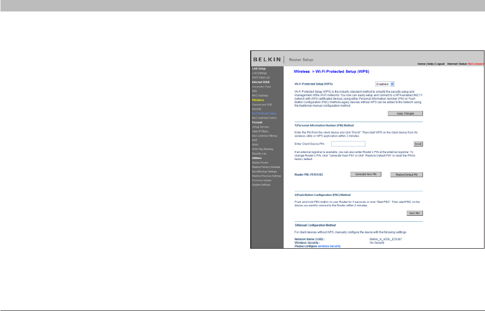
1. Wi-Fi Protected Setup (WPS): Enabled or Disabled.
2. Personal Identification Number (PIN) Method: In this method, a
wireless client wishing to access your network must supply an 8-digit
PIN to the Router. After clicking “Enroll”, you must start the WPS
handshaking procedure from the client within two minutes.
3. Router PIN: If an external registrar is available, you may enter in the
Router’s PIN to the registrar. Click “Generate New PIN” to change the
PIN from the default value. Click “Restore Default PIN” to reset the
PIN value.
4. Push Button Configuration (PBC) Method: PBC is an alternate method
to connect to a WPS network. Push the PBC button located on the
front of the Router for three seconds, and then initiate the PBC on the
client device. Alternatively, push the “Start PBC” soft button to start
this process.
5. Manual Configuration Method: This section lists the default security
settings if not using WPS.
The Router features WPA2, which is the second generation of the
WPA-based 802.11i standard. It offers a higher level of wireless
security by combining advanced network authentication and stronger
Advanced Encryption Standard (AES) encryption methods.
IMPORTANT: In order to use WPA2 security, all your computers
and wireless client adapters must be upgraded with patches, driver,
and client utility software that supported WPA2. At the time of this
User Manual’s publication, a couple security patches are available,
for free download, from Microsoft®. These patches work only with
the Windows XP operating system. Other operating systems are not
supported at this time.
For Windows XP with Service Pack 2, Microsoft has released a free
download to update the wireless client components to support WPA2
(KB971021). The update is available from:
http://support.microsoft.com/kb/917021
IMPORTANT: You also need to ensure that all your wireless client
cards/adapters support WPA2, and that you have downloaded and
installed the latest driver. Most of the Belkin wireless cards have
driver updates available for download from the Belkin support site:
www.belkin.com/networking.