Bosch Security Systems DL-ZB Motion sensor User Manual F01U314054 02c RFDL ZB ING indd
Bosch Security Systems, Inc. Motion sensor F01U314054 02c RFDL ZB ING indd
UserManual.wiki
>
Bosch Security Systems
>
DL-ZB User Manual
>
Users Manual
Contents
1.
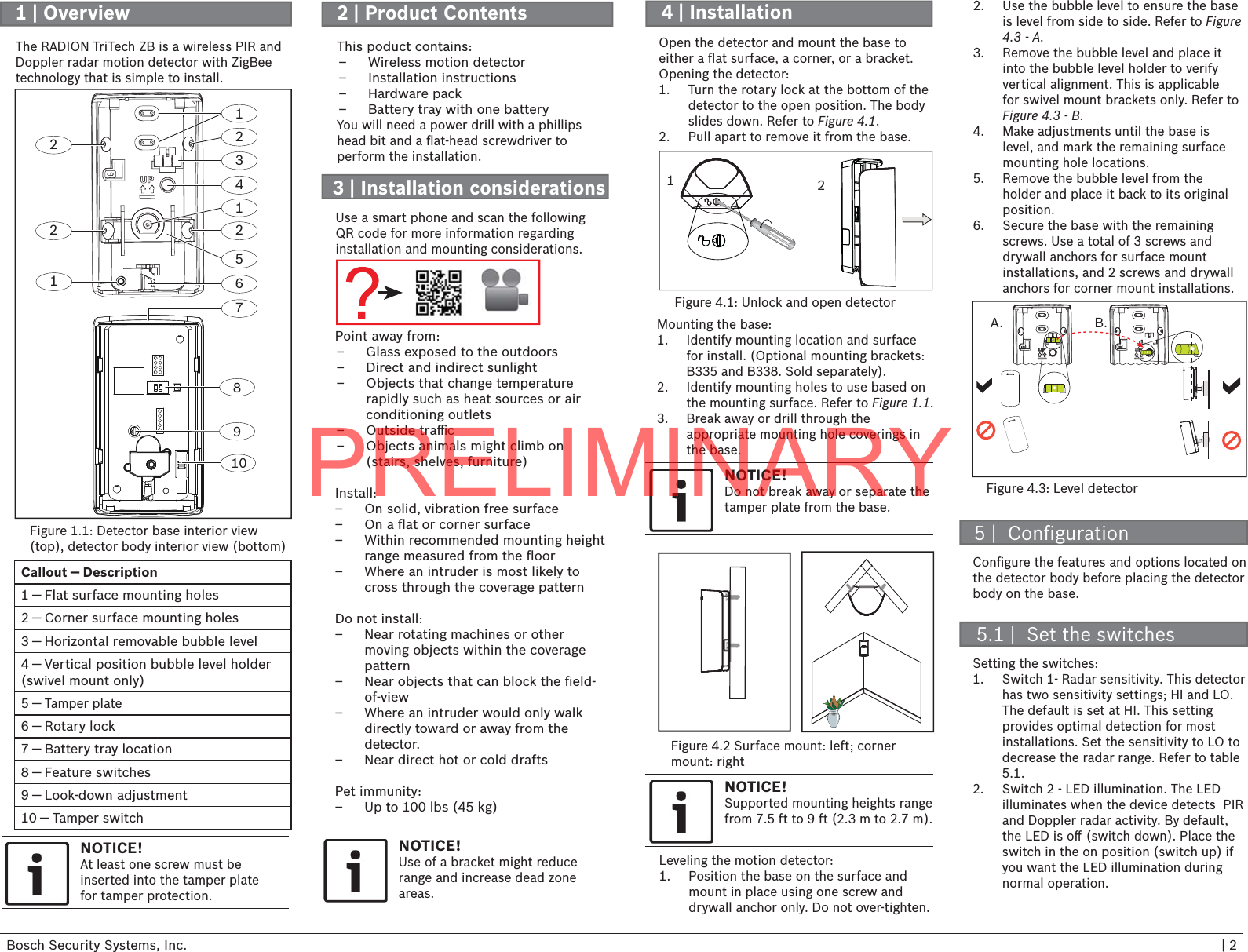
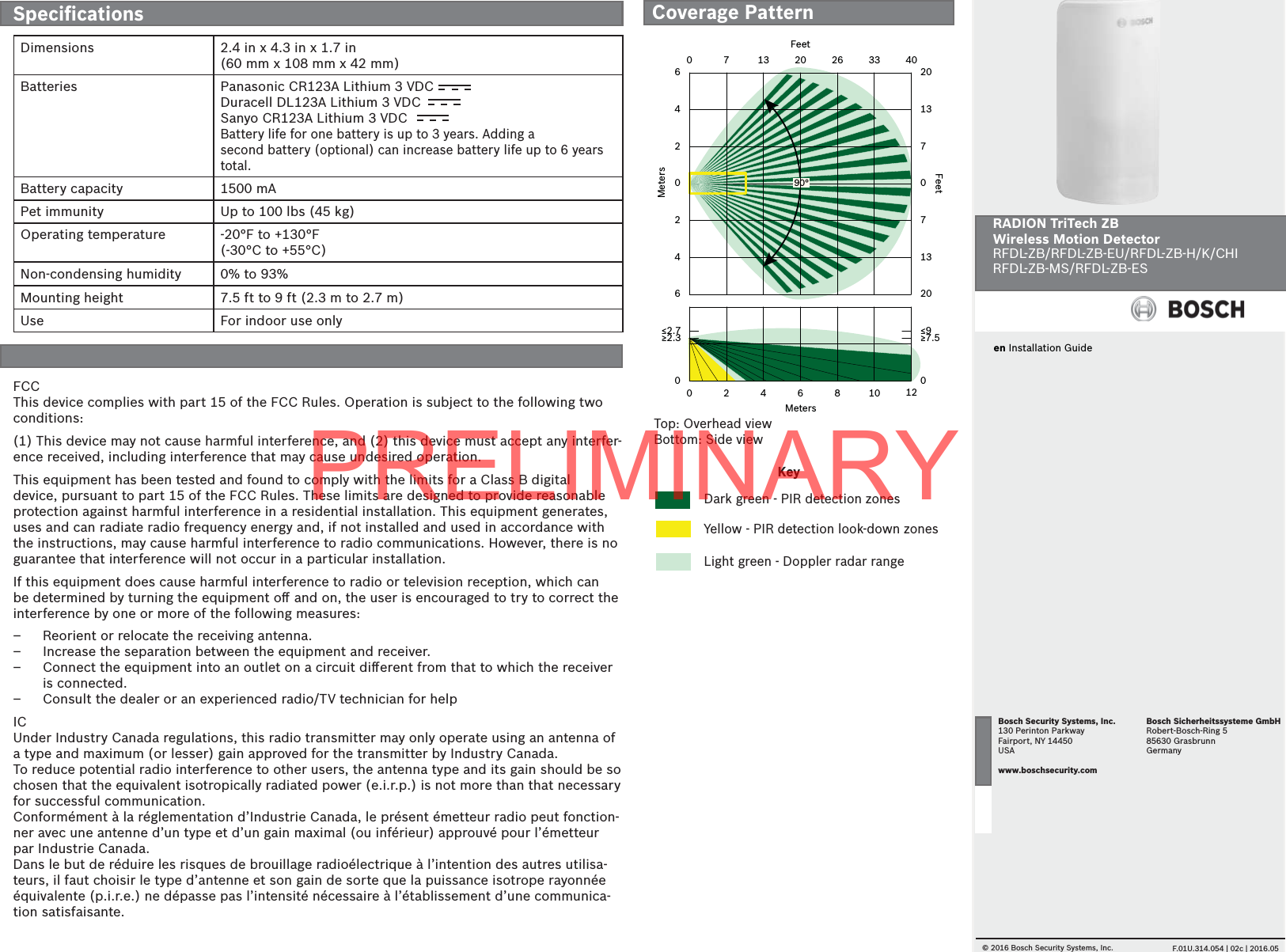
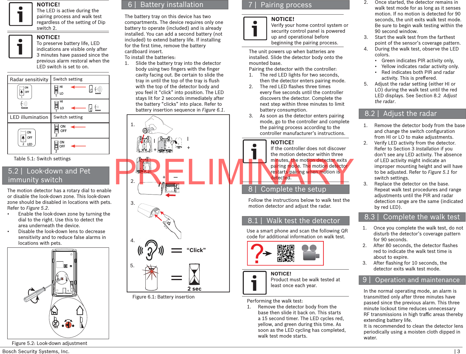
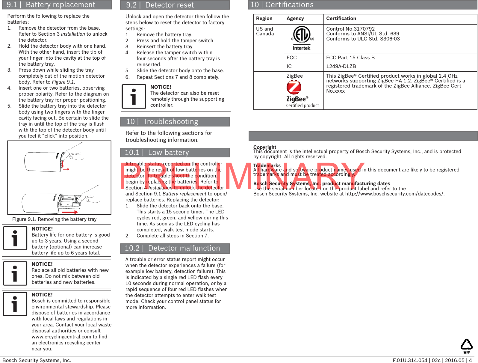
Users Manual
2.
Users Manual
Users Manual
Users Manual
Navigation menu
Upload a User Manual
Namespaces
Wiki Guide
HTML
PDF
Info
Views
User Manual
Discussion / Help
Navigation