CeoTronics CT-DECTCASE CT-DECT Case User Manual dok1200 gb
CeoTronics AG CT-DECT Case dok1200 gb
UserManual.wiki
>
CeoTronics
>
CT-DECTCASE User Manual
>
Manual
Contents
1.
Manual
2.
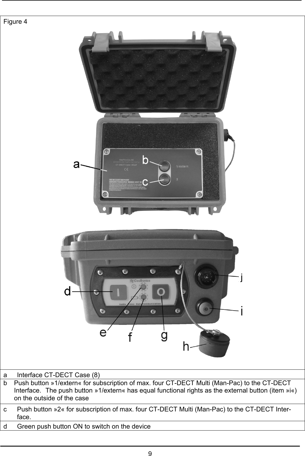
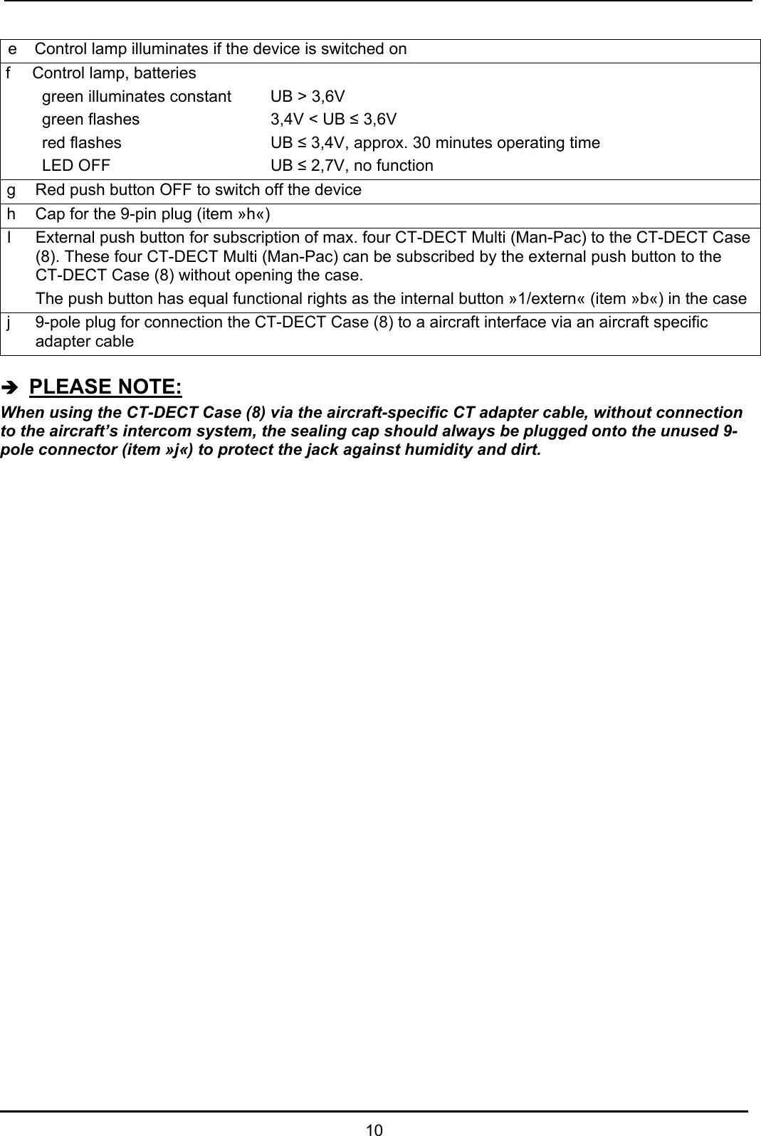
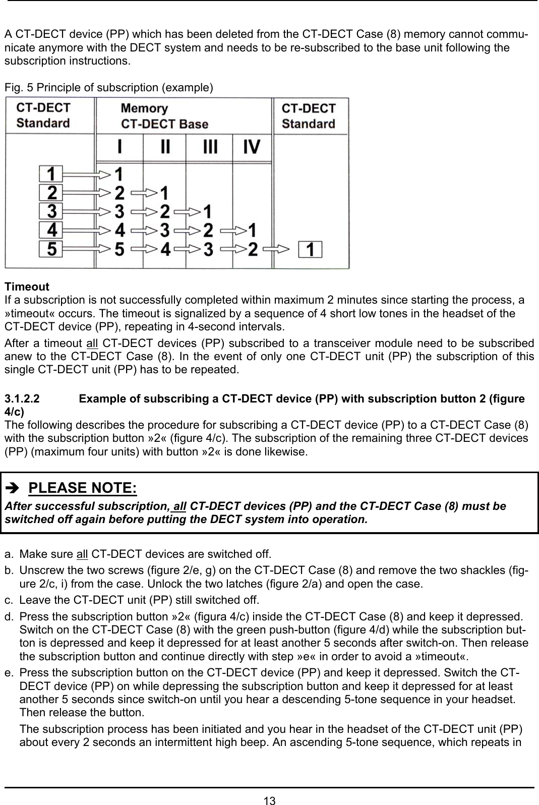
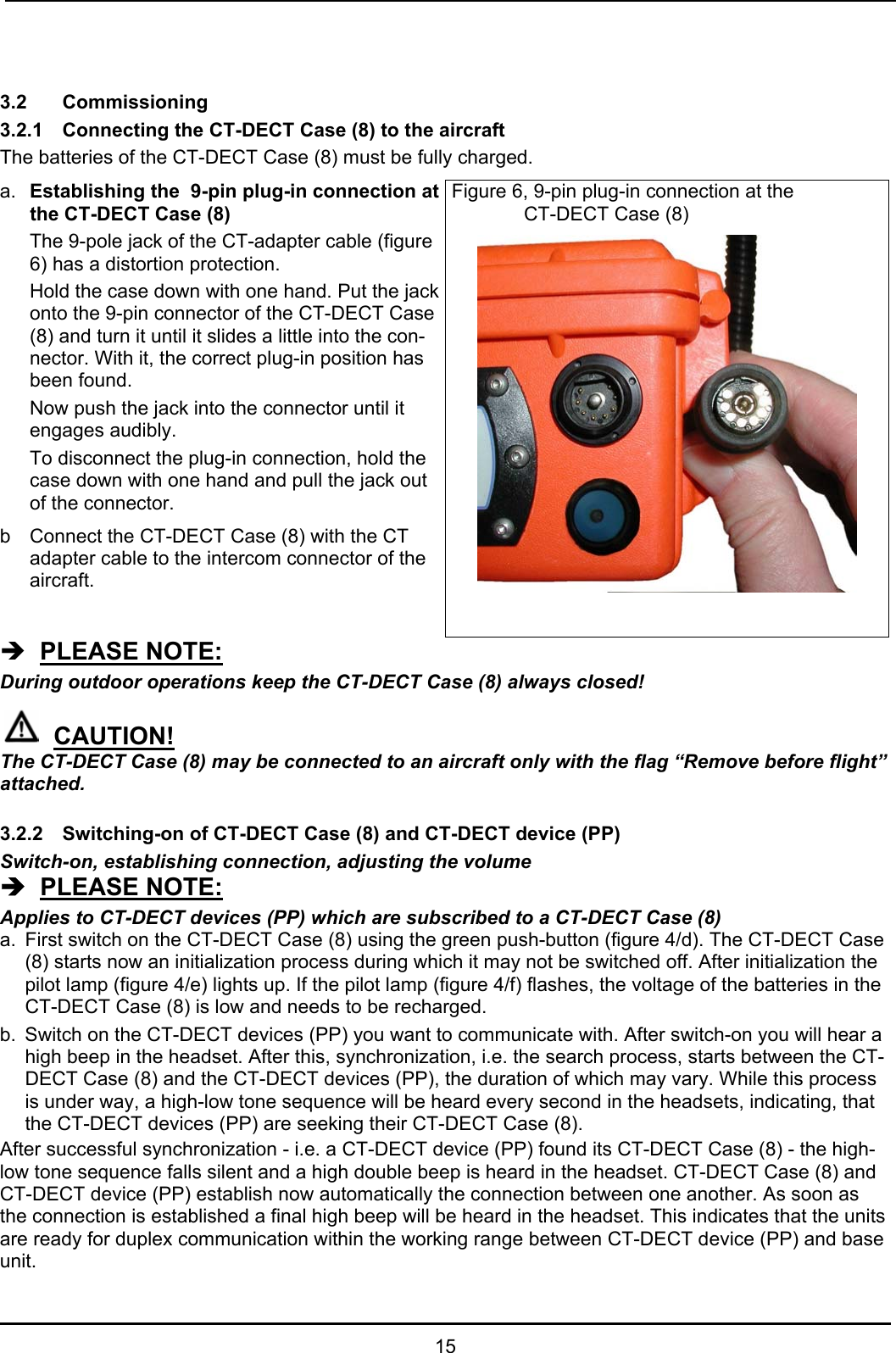
User Manual
Manual
Navigation menu
Upload a User Manual
Namespaces
Wiki Guide
HTML
PDF
Info
Views
User Manual
Discussion / Help
Navigation